EP4567239A1 - A roof window with a lifting device - Google Patents
A roof window with a lifting device Download PDFInfo
- Publication number
- EP4567239A1 EP4567239A1 EP24218105.5A EP24218105A EP4567239A1 EP 4567239 A1 EP4567239 A1 EP 4567239A1 EP 24218105 A EP24218105 A EP 24218105A EP 4567239 A1 EP4567239 A1 EP 4567239A1
- Authority
- EP
- European Patent Office
- Prior art keywords
- sledge
- roof window
- adjustment
- frame
- lifting arm
- Prior art date
- Legal status (The legal status is an assumption and is not a legal conclusion. Google has not performed a legal analysis and makes no representation as to the accuracy of the status listed.)
- Pending
Links
Images



Classifications
-
- E—FIXED CONSTRUCTIONS
- E04—BUILDING
- E04D—ROOF COVERINGS; SKY-LIGHTS; GUTTERS; ROOF-WORKING TOOLS
- E04D13/00—Special arrangements or devices in connection with roof coverings; Protection against birds; Roof drainage ; Sky-lights
- E04D13/03—Sky-lights; Domes; Ventilating sky-lights
- E04D13/035—Sky-lights; Domes; Ventilating sky-lights characterised by having movable parts
- E04D13/0351—Sky-lights; Domes; Ventilating sky-lights characterised by having movable parts the parts pivoting about a fixed axis
- E04D13/0354—Sky-lights; Domes; Ventilating sky-lights characterised by having movable parts the parts pivoting about a fixed axis the parts being flat
-
- E—FIXED CONSTRUCTIONS
- E04—BUILDING
- E04D—ROOF COVERINGS; SKY-LIGHTS; GUTTERS; ROOF-WORKING TOOLS
- E04D13/00—Special arrangements or devices in connection with roof coverings; Protection against birds; Roof drainage ; Sky-lights
- E04D13/03—Sky-lights; Domes; Ventilating sky-lights
- E04D13/035—Sky-lights; Domes; Ventilating sky-lights characterised by having movable parts
- E04D13/0357—Sky-lights; Domes; Ventilating sky-lights characterised by having movable parts the parts pivoting about an axis supported on a hinged frame or arms
-
- E—FIXED CONSTRUCTIONS
- E05—LOCKS; KEYS; WINDOW OR DOOR FITTINGS; SAFES
- E05D—HINGES OR SUSPENSION DEVICES FOR DOORS, WINDOWS OR WINGS
- E05D15/00—Suspension arrangements for wings
- E05D15/40—Suspension arrangements for wings supported on arms movable in vertical planes
- E05D15/46—Suspension arrangements for wings supported on arms movable in vertical planes with two pairs of pivoted arms
- E05D15/466—Suspension arrangements for wings supported on arms movable in vertical planes with two pairs of pivoted arms specially adapted for windows
-
- E—FIXED CONSTRUCTIONS
- E05—LOCKS; KEYS; WINDOW OR DOOR FITTINGS; SAFES
- E05F—DEVICES FOR MOVING WINGS INTO OPEN OR CLOSED POSITION; CHECKS FOR WINGS; WING FITTINGS NOT OTHERWISE PROVIDED FOR, CONCERNED WITH THE FUNCTIONING OF THE WING
- E05F1/00—Closers or openers for wings, not otherwise provided for in this subclass
- E05F1/08—Closers or openers for wings, not otherwise provided for in this subclass spring-actuated, e.g. for horizontally sliding wings
- E05F1/10—Closers or openers for wings, not otherwise provided for in this subclass spring-actuated, e.g. for horizontally sliding wings for swinging wings, e.g. counterbalance
- E05F1/1041—Closers or openers for wings, not otherwise provided for in this subclass spring-actuated, e.g. for horizontally sliding wings for swinging wings, e.g. counterbalance with a coil spring perpendicular to the pivot axis
- E05F1/1066—Closers or openers for wings, not otherwise provided for in this subclass spring-actuated, e.g. for horizontally sliding wings for swinging wings, e.g. counterbalance with a coil spring perpendicular to the pivot axis with a traction spring
- E05F1/1075—Closers or openers for wings, not otherwise provided for in this subclass spring-actuated, e.g. for horizontally sliding wings for swinging wings, e.g. counterbalance with a coil spring perpendicular to the pivot axis with a traction spring for counterbalancing
-
- E—FIXED CONSTRUCTIONS
- E05—LOCKS; KEYS; WINDOW OR DOOR FITTINGS; SAFES
- E05F—DEVICES FOR MOVING WINGS INTO OPEN OR CLOSED POSITION; CHECKS FOR WINGS; WING FITTINGS NOT OTHERWISE PROVIDED FOR, CONCERNED WITH THE FUNCTIONING OF THE WING
- E05F1/00—Closers or openers for wings, not otherwise provided for in this subclass
- E05F1/08—Closers or openers for wings, not otherwise provided for in this subclass spring-actuated, e.g. for horizontally sliding wings
- E05F1/10—Closers or openers for wings, not otherwise provided for in this subclass spring-actuated, e.g. for horizontally sliding wings for swinging wings, e.g. counterbalance
- E05F1/12—Mechanisms in the shape of hinges or pivots, operated by springs
- E05F1/1246—Mechanisms in the shape of hinges or pivots, operated by springs with a coil spring perpendicular to the pivot axis
- E05F1/1253—Mechanisms in the shape of hinges or pivots, operated by springs with a coil spring perpendicular to the pivot axis with a compression spring
- E05F1/1261—Mechanisms in the shape of hinges or pivots, operated by springs with a coil spring perpendicular to the pivot axis with a compression spring for counterbalancing
-
- E—FIXED CONSTRUCTIONS
- E05—LOCKS; KEYS; WINDOW OR DOOR FITTINGS; SAFES
- E05Y—INDEXING SCHEME ASSOCIATED WITH SUBCLASSES E05D AND E05F, RELATING TO CONSTRUCTION ELEMENTS, ELECTRIC CONTROL, POWER SUPPLY, POWER SIGNAL OR TRANSMISSION, USER INTERFACES, MOUNTING OR COUPLING, DETAILS, ACCESSORIES, AUXILIARY OPERATIONS NOT OTHERWISE PROVIDED FOR, APPLICATION THEREOF
- E05Y2201/00—Constructional elements; Accessories therefor
- E05Y2201/40—Motors; Magnets; Springs; Weights; Accessories therefor
- E05Y2201/404—Function thereof
- E05Y2201/416—Function thereof for counterbalancing
-
- E—FIXED CONSTRUCTIONS
- E05—LOCKS; KEYS; WINDOW OR DOOR FITTINGS; SAFES
- E05Y—INDEXING SCHEME ASSOCIATED WITH SUBCLASSES E05D AND E05F, RELATING TO CONSTRUCTION ELEMENTS, ELECTRIC CONTROL, POWER SUPPLY, POWER SIGNAL OR TRANSMISSION, USER INTERFACES, MOUNTING OR COUPLING, DETAILS, ACCESSORIES, AUXILIARY OPERATIONS NOT OTHERWISE PROVIDED FOR, APPLICATION THEREOF
- E05Y2201/00—Constructional elements; Accessories therefor
- E05Y2201/40—Motors; Magnets; Springs; Weights; Accessories therefor
- E05Y2201/47—Springs
- E05Y2201/488—Traction springs
-
- E—FIXED CONSTRUCTIONS
- E05—LOCKS; KEYS; WINDOW OR DOOR FITTINGS; SAFES
- E05Y—INDEXING SCHEME ASSOCIATED WITH SUBCLASSES E05D AND E05F, RELATING TO CONSTRUCTION ELEMENTS, ELECTRIC CONTROL, POWER SUPPLY, POWER SIGNAL OR TRANSMISSION, USER INTERFACES, MOUNTING OR COUPLING, DETAILS, ACCESSORIES, AUXILIARY OPERATIONS NOT OTHERWISE PROVIDED FOR, APPLICATION THEREOF
- E05Y2201/00—Constructional elements; Accessories therefor
- E05Y2201/40—Motors; Magnets; Springs; Weights; Accessories therefor
- E05Y2201/499—Spring tensioners; Tension sensors
-
- E—FIXED CONSTRUCTIONS
- E05—LOCKS; KEYS; WINDOW OR DOOR FITTINGS; SAFES
- E05Y—INDEXING SCHEME ASSOCIATED WITH SUBCLASSES E05D AND E05F, RELATING TO CONSTRUCTION ELEMENTS, ELECTRIC CONTROL, POWER SUPPLY, POWER SIGNAL OR TRANSMISSION, USER INTERFACES, MOUNTING OR COUPLING, DETAILS, ACCESSORIES, AUXILIARY OPERATIONS NOT OTHERWISE PROVIDED FOR, APPLICATION THEREOF
- E05Y2201/00—Constructional elements; Accessories therefor
- E05Y2201/60—Suspension or transmission members; Accessories therefor
- E05Y2201/622—Suspension or transmission members elements
- E05Y2201/624—Arms
- E05Y2201/626—Levers
-
- E—FIXED CONSTRUCTIONS
- E05—LOCKS; KEYS; WINDOW OR DOOR FITTINGS; SAFES
- E05Y—INDEXING SCHEME ASSOCIATED WITH SUBCLASSES E05D AND E05F, RELATING TO CONSTRUCTION ELEMENTS, ELECTRIC CONTROL, POWER SUPPLY, POWER SIGNAL OR TRANSMISSION, USER INTERFACES, MOUNTING OR COUPLING, DETAILS, ACCESSORIES, AUXILIARY OPERATIONS NOT OTHERWISE PROVIDED FOR, APPLICATION THEREOF
- E05Y2201/00—Constructional elements; Accessories therefor
- E05Y2201/60—Suspension or transmission members; Accessories therefor
- E05Y2201/622—Suspension or transmission members elements
- E05Y2201/696—Screw mechanisms
-
- E—FIXED CONSTRUCTIONS
- E05—LOCKS; KEYS; WINDOW OR DOOR FITTINGS; SAFES
- E05Y—INDEXING SCHEME ASSOCIATED WITH SUBCLASSES E05D AND E05F, RELATING TO CONSTRUCTION ELEMENTS, ELECTRIC CONTROL, POWER SUPPLY, POWER SIGNAL OR TRANSMISSION, USER INTERFACES, MOUNTING OR COUPLING, DETAILS, ACCESSORIES, AUXILIARY OPERATIONS NOT OTHERWISE PROVIDED FOR, APPLICATION THEREOF
- E05Y2201/00—Constructional elements; Accessories therefor
- E05Y2201/60—Suspension or transmission members; Accessories therefor
- E05Y2201/622—Suspension or transmission members elements
- E05Y2201/696—Screw mechanisms
- E05Y2201/70—Nuts
-
- E—FIXED CONSTRUCTIONS
- E05—LOCKS; KEYS; WINDOW OR DOOR FITTINGS; SAFES
- E05Y—INDEXING SCHEME ASSOCIATED WITH SUBCLASSES E05D AND E05F, RELATING TO CONSTRUCTION ELEMENTS, ELECTRIC CONTROL, POWER SUPPLY, POWER SIGNAL OR TRANSMISSION, USER INTERFACES, MOUNTING OR COUPLING, DETAILS, ACCESSORIES, AUXILIARY OPERATIONS NOT OTHERWISE PROVIDED FOR, APPLICATION THEREOF
- E05Y2201/00—Constructional elements; Accessories therefor
- E05Y2201/60—Suspension or transmission members; Accessories therefor
- E05Y2201/622—Suspension or transmission members elements
- E05Y2201/708—Sliders
-
- E—FIXED CONSTRUCTIONS
- E05—LOCKS; KEYS; WINDOW OR DOOR FITTINGS; SAFES
- E05Y—INDEXING SCHEME ASSOCIATED WITH SUBCLASSES E05D AND E05F, RELATING TO CONSTRUCTION ELEMENTS, ELECTRIC CONTROL, POWER SUPPLY, POWER SIGNAL OR TRANSMISSION, USER INTERFACES, MOUNTING OR COUPLING, DETAILS, ACCESSORIES, AUXILIARY OPERATIONS NOT OTHERWISE PROVIDED FOR, APPLICATION THEREOF
- E05Y2600/00—Mounting or coupling arrangements for elements provided for in this subclass
- E05Y2600/10—Adjustable
- E05Y2600/12—Adjustable by manual operation
-
- E—FIXED CONSTRUCTIONS
- E05—LOCKS; KEYS; WINDOW OR DOOR FITTINGS; SAFES
- E05Y—INDEXING SCHEME ASSOCIATED WITH SUBCLASSES E05D AND E05F, RELATING TO CONSTRUCTION ELEMENTS, ELECTRIC CONTROL, POWER SUPPLY, POWER SIGNAL OR TRANSMISSION, USER INTERFACES, MOUNTING OR COUPLING, DETAILS, ACCESSORIES, AUXILIARY OPERATIONS NOT OTHERWISE PROVIDED FOR, APPLICATION THEREOF
- E05Y2600/00—Mounting or coupling arrangements for elements provided for in this subclass
- E05Y2600/10—Adjustable
- E05Y2600/20—Adjustable with specific transmission movement
-
- E—FIXED CONSTRUCTIONS
- E05—LOCKS; KEYS; WINDOW OR DOOR FITTINGS; SAFES
- E05Y—INDEXING SCHEME ASSOCIATED WITH SUBCLASSES E05D AND E05F, RELATING TO CONSTRUCTION ELEMENTS, ELECTRIC CONTROL, POWER SUPPLY, POWER SIGNAL OR TRANSMISSION, USER INTERFACES, MOUNTING OR COUPLING, DETAILS, ACCESSORIES, AUXILIARY OPERATIONS NOT OTHERWISE PROVIDED FOR, APPLICATION THEREOF
- E05Y2800/00—Details, accessories and auxiliary operations not otherwise provided for
- E05Y2800/15—Applicability
- E05Y2800/17—Universally applicable
- E05Y2800/176—Universally applicable on different wing types, weights or sizes
-
- E—FIXED CONSTRUCTIONS
- E05—LOCKS; KEYS; WINDOW OR DOOR FITTINGS; SAFES
- E05Y—INDEXING SCHEME ASSOCIATED WITH SUBCLASSES E05D AND E05F, RELATING TO CONSTRUCTION ELEMENTS, ELECTRIC CONTROL, POWER SUPPLY, POWER SIGNAL OR TRANSMISSION, USER INTERFACES, MOUNTING OR COUPLING, DETAILS, ACCESSORIES, AUXILIARY OPERATIONS NOT OTHERWISE PROVIDED FOR, APPLICATION THEREOF
- E05Y2900/00—Application of doors, windows, wings or fittings thereof
- E05Y2900/10—Application of doors, windows, wings or fittings thereof for buildings or parts thereof
- E05Y2900/13—Type of wing
- E05Y2900/148—Windows
- E05Y2900/152—Roof windows
Definitions
- the present invention relates to a roof window, particularly for installation in or on a roof surface having an inclination, comprising a primary frame, at least one secondary frame, such as a sash and/or an intermediate frame, and a lifting device comprising an adjustment system comprised in a sledge, the lifting device further comprising a spring assembly configured to be coupled to the sledge, and a linkage system being rotatably connected to the sledge through the adjustment system and connected to the secondary frame, wherein the linkage system comprises a lifting arm with a first end rotatably connected to the adjustment system, and the adjustment system is adapted to move the first end of the lifting arm upon activation of the adjustment system.
- Windows for installation in an inclined roof surface may be provided in a number of varieties and include more or less complicated operational structures to allow opening of the sash and to fulfil other functions, such as ventilation.
- Such roof windows include the type hinged at or near the centre, the top-hinged type, and finally the roof windows that are top-hinged during normal operation but in which the sash is able to perform a rotating movement substantially at a centre axis, either for cleaning or for providing an alternative manner of operation.
- Roof windows of the top-hinged type have a first hinge axis provided by a top hinge arrangement to provide a first operational condition, whereas rotation of the sash in a second operational condition is performed by means of an intermediate frame in which the sash is hinged to provide a secondary hinge axis.
- one hinge of the hinge arrangement will be located at either side of the roof window to define a substantially horizontal hinge axis.
- top-hinged windows with a second operational condition are for instance disclosed in Applicant's WO-A-89/10460 , EP 0 733146 B1 , EP 1 873 323 B1 , EP 2 762 665 A2 , and WO 2019101281 A1 .
- the sash structure is connected with an intermediate frame with frame arms, which in the closed position of the window are positioned between the upper parts of the frame and sash side members, and which during normal use of the window as a top-hung window follow the sash side members.
- the opening of a roof window and the force required to operate the window is affected by the inclination of the roof in which the window is installed.
- Such a lifting device is for instance disclosed in the Applicant's WO2019/101281 A1 where a spring assembly acts as a force balancing element to the pane-carrying frame by operating on a lifting arm attached to the frame.
- a roof window of the kind mentioned in the introduction which is further characterised in that the sledge is slidably connected to the primary frame in a sledge guide.
- This arrangement provides an alternative connection of the linkage system to the sledge and a versatile solution for adjusting to different roof inclinations. Furthermore, the linkage system has a simple structure which may minimize the cost of manufacturing and allow easy installation and assembly of the system.
- the adjustment system comprises an adjustment screw and an adjustment bushing, and wherein the first end of the lifting arm is connected to the adjustment screw via the adjustment bushing.
- the adjustment system provides a mechanism for adjusting the balance between the weight of the pane-carrying sash with the force provided by the spring assembly.
- the weight of the pane-carrying sash is at least partially carried by the lifting arm when the roof window is in an open position and the lifting arm is arranged such that the weight of the pane-carrying sash acts as a pulling force on the spring in the spring assembly.
- the stretched spring provides a spring force towards the equilibrium position of the spring which forces the pane-carrying sash towards an open position.
- the weight carried by the lifting arm depends on the roof inclination of the roof in which the roof window is installed.
- the balance between the spring force and the force from the weight of pane-carrying sash acting on the lifting arm may therefore change when the roof inclination is changed.
- the adjustment system is arranged to adjust the balance between the force exerted by the lifting arm on the pane-carrying sash and the weight of the pane-carrying sash.
- the adjustment system may be adjusted to balance roof window for roof inclinations in the range of 15 - 65°.
- the adjustment screw acts as a connecting link between one or more elements of the roof window, where one element is the lifting arm, allowing the connected elements to be moved relative to each other when the adjustment screw is adjusted.
- the adjustment screw comprises an adjustment screw shaft, an adjustment screw head, and an adjustment screw top.
- the adjustment screw is connected to the lifting arm via the adjustment screw top and the adjustment screw is thereby stationary relative to the lifting arm when the adjustment screw is adjusted.
- one or more elements of the roof window are connected to the adjustment screw shaft.
- the position of the one or more elements on the adjustment screw shaft is arranged to be adjusted when the adjustment screw is manipulated.
- the adjustment screw head is arranged to be manipulated by an external force such as the force from a screw bit in order to rotate the adjustment screw.
- the one or more elements connected to the adjustment screw shaft is arranged to be moved relative to the lifting arm. This arrangement changes the balance between the weight of the pane-carrying frame and the force exerted by the lifting arm on the pane-carrying frame from the pull of the spring assembly.
- a roof window 100 is shown.
- the roof window 100 is intended to be installed in or on an inclined roof surface (not shown).
- the roof window 100 comprises a primary frame 1, a secondary frame which in the following will be referred to as a sash 2 but which could also include an intermediate frame connected partly to the primary frame 1, partly to a separate, glass-carrying unit functioning as a sash, and a pane 4.
- the roof window comprises a windowpane comprising at least two layers of glass, preferably at least three layers of glass.
- the window may comprise an Insulating Glazing Unit (IGU).
- IGU Insulating Glazing Unit
- the primary frame 1 comprises a set of frame members including a top frame member, two side frame members and a bottom frame member.
- the sash 2 comprises a set of sash members including a top sash member, two side sash members and a bottom sash member. While the primary frame 1 and sash 2 are described as rectangular structures, some principles of the presented concepts may be applicable to other geometrical shapes as well.
- the pane 4 comprises a number of edge portions generally associated to members of the sash 2.
- An exterior pane surface 4e defines a plane of the roof window 100 in an assembled condition of the roof window 100.
- the assembled condition of the roof window 100 is achieved when main components of the primary frame 1 and sash 2 have been assembled and the primary frame 1 and sash 2 are connected to each other, for instance in an installed position when the roof window 100 is ready for use.
- an assembled condition of the sash 2 is achieved once main components of the sash 2 have been assembled, and an assembled condition of the primary frame 1 when main components of the primary frame 1 are assembled.
- main components is to be understood as encompassing primary parts of the roof window necessary to perform all operational functions, and not including accessories or auxiliary equipment.
- An interior pane surface 4i faces the interior, typically a room of a building subjacent the roof surface in which the roof window 100 is installed.
- the sash 2 is openable relative to the primary frame 1, to obtain one or more open positions. In such open positions, the sash 2 and pane 4 are moved out of the plane of the roof window 1.
- the sash 2 is shown as being top-hung, i.e. during normal use, the sash 2 is rotated about a substantially horizontal hinge axis at or near the top frame member and top sash member at the top of the roof window 100. It is however conceivable to apply some principles of the presented concepts for roof windows on different types of windows having other opening patterns.
- FIG 1A Further details shown in Fig 1A include an operating assembly 5, here shown as a handle. Other operating assemblies may be present as well.
- a representative mounting bracket forming part of a plurality of mounting brackets forming a load-transferring connection between the roof window 100 and a surrounding roof structure (not shown).
- a roof structure may include rafters and battens, plywood or other construction materials.
- An insulating frame 7 is shown. Insulation by an insulating frame is optional and may be provided along only some of the frame members or as shown surrounding all four frame members.
- Fig. 1C shows a top-hung roof window 100.
- the roof window is top-hung, i.e., hinged at the top, by means of a hinge assembly (not shown) connecting the primary frame with the secondary frame.
- the hinge assembly is configured in such a way that it allows the sash 2 to be top-hung in a first operational condition corresponding to normal use. That is, during normal use the sash 2 is rotated about a substantially horizontal first hinge axis at or near the top frame member and top sash member between a closed position and an open position.
- the lifting device 10 comprises a lifting arm 14 inserted between the primary frame 1 and the at least one secondary frame, here the sash 2.
- the lifting arm 14 comprises a first end 14a and a second end 14b (cf. Fig. 7 ).
- the roof window 100 in Fig. 1C is shown with one lifting device 10 arranged between a side member of primary frame 1 and a side member of the sash 2.
- the roof window also comprises a second lifting device between the other sash side member and frame side member.
- a lifting device on each side ensures better support of the windowpane, improves the handling of the roof window and reduces the forces required in each lifting device.
- the lifting device 10 is shown in greater details in Fig. 2 .
- the sledge 30 of the lifting device 10 comprises an adjustment system 50.
- the adjustment system slides with the sledge in the sledge guide 16. It is conceivable that the sledge may be exchanged with a sledge of a different kind comprising a different adjustment system.
- the lifting device can in this way be tailored for specific requirements.
- the sledge 30 is attached to a spring assembly 20 which is arranged to exert a force on the sledge 30.
- the sledge 30 may be uncoupled from the spring assembly 20. This may, as an example, be an advantage during installation of the roof window where a spring force acting on the sledge 30 may make it difficult to handle the roof window.
- the sledge 30 and the spring assembly 20 are initially in an uncoupled state.
- the spring assembly 20 and the sledge 30 are then coupled by opening the roof window resulting in the sledge 30 sliding towards a coupling device such as a hook attached to a spring comprised in the spring assembly 20.
- the pulling force of the spring and the weight of the roof window are preferably balanced such that the roof window can be positioned in an open position without closing due to its own weight or opening further due to the pull from the spring in the spring assembly. This balance is also influenced by the inclination of the roof that the roof window is installed in.
- the spring in the spring assembly 30 may be adjusted to balance the roof window in a specific roof inclination.
- the spring force acting on the sledge will not be balanced to the weight of the movable parts of the roof window.
- the spring may exert too much force on the window thereby forcing the window to open further.
- the spring may be too weak, and the window will close due to its own weight. In both cases, the window is difficult for the user to operate and potentially hazardous.
- the adjustment system 50 provides a way to easily adjust the roof window according to a roof inclination in the range of 15 - 65°.
- the adjustment system 50 is adapted to move the first end 14a of the lifting arm 14 upon activation of the adjustment system. Preferably, this movement is in a height direction H which is substantially perpendicular to the sliding direction. Moving the first end 14a of the lifting arm 14 in a direction substantially perpendicular to the sliding direction has the effect of changing the height position of the first end 14a of the lifting device 14 in the sledge guide.
- the first end 14a of the lifting arm 14 holds this height position until the adjustment system 50 is activated again, but the lifting arm 14 is still capable of sliding in the sledge guide 16 via the sledge 30 regardless of the height position of the first end 14a of the lifting arm 14 within the meaning of the adjustment range of the adjustment system 50.
- the adjustment system 50 preferably comprises an adjustment screw 51 and an adjustment bushing 54 as shown in Fig. 3 .
- the adjustment screw 51 may be fastened to the sledge 30 by means of an adjustment base 56. Additionally and/or alternatively, the adjustment screw 51 penetrates the sledge 30 and sledge guide 16, as shown in Fig. 2 and 3 .
- the sledge guide 16 comprises a track 43 configured for the adjustment screw 51, such as shown in Fig. 3 .
- the adjustment screw 51 may be accommodated in an opening 15 in the sledge 30 such as shown in Figs 2 and 6 .
- the adjustment screw is configured along the opening 15 and the adjustment bushing 54 is configured to move in the opening 15.
- the adjustment screw 51 is accommodated on the sledge 30 such as on an extrusion of the sledge 30, as shown in Fig. 3 .
- the lifting arm 14 may be connected to the adjustment bushing 54 via an adjustment arm 52.
- the lifting arm 14 may be connected directly to the adjustment bushing 54.
- the adjustment arm 52 is preferably rotationally fixed at a first end to the sledge 30, rotationally fixed at a second end to the lifting arm 14, and connected to the adjustment bushing 54 at a point between the first and second end.
- the adjustment arm 52 may be elongate in shape. It may alternatively have a small angle giving it a hockey stick shape.
- the adjustment arm 52 may comprise a first adjustment arm 521 and a second adjustment arm 522 configured on opposite sides of the sledge 30.
- the lifting arm 14 has a first end 14a, which is rotatably connected to the sledge 30.
- the lifting arm 14 is comprised in a linkage system 19 which connects the primary frame 1 with the secondary frame 2.
- the lifting arm 14 is generally elongate in shape. It may have a bend giving it the general shape of a hockey stick.
- the lifting arm 14 comprised in the linkage system 19 is rotationally fixed to the secondary frame 2 via a rivet and/or axle 41.
- the lifting arm 14 extends from the sledge 30 in the sledge guide 16 of the primary frame 1 to the secondary frame 2, as shown in Figs 4 and 5 .
- the linkage system 19 comprises an intermediate arm 45.
- the intermediate 45 is generally elongated with a first end, a second end and a middle portion.
- the intermediate arm is connected at a first point to the sledge guide 16. This first point may be at a first end of the intermediate arm 45.
- the intermediate arm is connected at a second point to the lifting arm 14.
- this second point is at an opposite end of the intermediate arm 45 compared to the first point.
- the intermediate arm 45 is connected to the lifting arm 14 at a point between the first end 14a and a second end 14b of the lifting arm 14.
- the second end 14b of the lifting arm 14 is arranged to move translationally along the secondary frame 2.
- the second end 14b of the lifting arm 14 may be configured to move translationally along the secondary frame by means of a sledge and sledge guide arranged on the lifting arm and secondary frame, respectively.
- the lifting arm 14 may be configured to move translationally along the secondary frame 2 by means of a wheel and wheel guide.
- Such a connection is illustrated in Fig. 7 where the second end 14b of the lifting arm 14 is configured to rotate and move translationally along the secondary frame 2.
- this second point of the intermediate arm 45 is substantially arranged on the middle portion of the intermediate arm 45.
- the intermediate arm 45 of the linkage system 19 is connected at a third point to the secondary frame 2.
- the intermediate arm 45 may be slidably connected to the sledge guide 16 and/or slidably connected to the secondary frame 2.
Landscapes
- Engineering & Computer Science (AREA)
- Architecture (AREA)
- Civil Engineering (AREA)
- Structural Engineering (AREA)
- Window Of Vehicle (AREA)
- Wing Frames And Configurations (AREA)
Abstract
A roof window (100), particularly for installation in or on a roof surface having an inclination, comprising a primary frame (1), at least one secondary frame (2, 3), such as a sash and/or an intermediate frame, and a lifting device (10) comprising an adjustment system (50) comprised in a sledge (30), the sledge (30) being slidably connected with the primary frame (1) in a sledge guide (16), the lifting device (10) further comprising a spring assembly (20) configured to be coupled to the sledge (30), and a linkage system (19) being, rotatably connected to the sledge (30) through the adjustment system (50), and connected to the secondary frame (2, 3), wherein the linkage system (19) comprises a lifting arm (14) with a first end (14a) rotatably connected to the adjustment system (50).
Description
- The present invention relates to a roof window, particularly for installation in or on a roof surface having an inclination, comprising a primary frame, at least one secondary frame, such as a sash and/or an intermediate frame, and a lifting device comprising an adjustment system comprised in a sledge, the lifting device further comprising a spring assembly configured to be coupled to the sledge, and a linkage system being rotatably connected to the sledge through the adjustment system and connected to the secondary frame, wherein the linkage system comprises a lifting arm with a first end rotatably connected to the adjustment system, and the adjustment system is adapted to move the first end of the lifting arm upon activation of the adjustment system.
- Windows for installation in an inclined roof surface may be provided in a number of varieties and include more or less complicated operational structures to allow opening of the sash and to fulfil other functions, such as ventilation. Such roof windows include the type hinged at or near the centre, the top-hinged type, and finally the roof windows that are top-hinged during normal operation but in which the sash is able to perform a rotating movement substantially at a centre axis, either for cleaning or for providing an alternative manner of operation. Roof windows of the top-hinged type have a first hinge axis provided by a top hinge arrangement to provide a first operational condition, whereas rotation of the sash in a second operational condition is performed by means of an intermediate frame in which the sash is hinged to provide a secondary hinge axis. Typically, one hinge of the hinge arrangement will be located at either side of the roof window to define a substantially horizontal hinge axis.
- Examples of top-hinged windows with a second operational condition are for instance disclosed in Applicant's
WO-A-89/10460 EP 0 733146 B1 ,EP 1 873 323 B1 ,EP 2 762 665 A2WO 2019101281 A1 . To make it possible to rotate the window sash approximately 180° to a convenient cleaning position, the sash structure is connected with an intermediate frame with frame arms, which in the closed position of the window are positioned between the upper parts of the frame and sash side members, and which during normal use of the window as a top-hung window follow the sash side members. - Furthermore, the opening of a roof window and the force required to operate the window is affected by the inclination of the roof in which the window is installed.
- In roof windows in which the operation takes place either entirely or partially about a hinge axis at the top, it is known to balance at least part of the weight of the movable components by means of a lifting device. The purpose of this arrangement is to facilitate opening the window, and the dimensions may be chosen so that a spring can retain the top-hinged frame in equilibrium in a desired opening position.
- Such a lifting device is for instance disclosed in the Applicant's
WO2019/101281 A1 where a spring assembly acts as a force balancing element to the pane-carrying frame by operating on a lifting arm attached to the frame. - Another example of a lifting device is disclosed in the Applicant's
EP 4 390 030 A1 - Yet another example of a lifting device is shown in
DE 31 26 531 A1 . - However, although the lifting device in the above example is to some extent capable of providing the desired force balance, there is still room for improvement.
- With this background it is an object of the present invention to provide a roof window with a lifting device having an increased design flexibility allowing the desired movement pattern and simple structure.
- This is achieved with a roof window of the kind mentioned in the introduction, which is further characterised in that the sledge is slidably connected to the primary frame in a sledge guide.
- This arrangement provides an alternative connection of the linkage system to the sledge and a versatile solution for adjusting to different roof inclinations. Furthermore, the linkage system has a simple structure which may minimize the cost of manufacturing and allow easy installation and assembly of the system.
- In a presently preferred embodiment, the adjustment system comprises an adjustment screw and an adjustment bushing, and wherein the first end of the lifting arm is connected to the adjustment screw via the adjustment bushing.
- In an embodiment, the adjustment system provides a mechanism for adjusting the balance between the weight of the pane-carrying sash with the force provided by the spring assembly. The weight of the pane-carrying sash is at least partially carried by the lifting arm when the roof window is in an open position and the lifting arm is arranged such that the weight of the pane-carrying sash acts as a pulling force on the spring in the spring assembly. The stretched spring provides a spring force towards the equilibrium position of the spring which forces the pane-carrying sash towards an open position. The weight carried by the lifting arm depends on the roof inclination of the roof in which the roof window is installed. The balance between the spring force and the force from the weight of pane-carrying sash acting on the lifting arm may therefore change when the roof inclination is changed. The adjustment system is arranged to adjust the balance between the force exerted by the lifting arm on the pane-carrying sash and the weight of the pane-carrying sash. The adjustment system may be adjusted to balance roof window for roof inclinations in the range of 15 - 65°.
- In an embodiment, the adjustment screw acts as a connecting link between one or more elements of the roof window, where one element is the lifting arm, allowing the connected elements to be moved relative to each other when the adjustment screw is adjusted. Generally, the adjustment screw comprises an adjustment screw shaft, an adjustment screw head, and an adjustment screw top. In preferred embodiments, the adjustment screw is connected to the lifting arm via the adjustment screw top and the adjustment screw is thereby stationary relative to the lifting arm when the adjustment screw is adjusted.
- In an embodiment, one or more elements of the roof window are connected to the adjustment screw shaft. The position of the one or more elements on the adjustment screw shaft is arranged to be adjusted when the adjustment screw is manipulated. The adjustment screw head is arranged to be manipulated by an external force such as the force from a screw bit in order to rotate the adjustment screw. By adjustment of the adjustment screw, the one or more elements connected to the adjustment screw shaft is arranged to be moved relative to the lifting arm. This arrangement changes the balance between the weight of the pane-carrying frame and the force exerted by the lifting arm on the pane-carrying frame from the pull of the spring assembly.
- Other presently preferred embodiments and further advantages will be apparent from the subsequent detailed description and drawings.
- In the following description, embodiments of the invention will be described with reference to the drawings, in which
-
Fig. 1A is a perspective view of a roof window in an embodiment according to the invention, in a first operational condition seen from an interior side. -
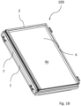
Fig. 1B is a perspective view of a roof window in an embodiment according to the invention, in a first operational condition, seen from an exterior side. -
Fig. 1C is a perspective view of a roof window in an embodiment according to the invention in a second operational condition seen from an exterior side with a lifting device according to an embodiment of the invention, and a perspective view of a lifting device in an embodiment according to the invention. -
Fig. 2 is a side view of a lifting device according to an embodiment of the invention, showing a height direction H. -
Fig. 3 is a perspective view of a lifting device according to an embodiment of the invention. -
Fig. 4 is a side view of a lifting device according to an embodiment of the invention in a closed condition. -
Fig. 5 is a side view of a lifting device according to an embodiment of the invention in an open condition. -
Fig. 6 is a side view of a lifting device according to another embodiment of the invention. -
Fig. 7 is a side view of a lifting device according to another embodiment of the invention. - In the following, embodiments of the lifting device and roof window will be described in further detail. When referring to the Figures, the terms up, down, upwards, downwards, top and bottom are taken relative to how the figures are displayed. A front view is taken from the hinge and viewing towards the frame. A view from behind is therefore taken as viewed from the frame towards the hinge. A longitudinal direction is, if nothing else is mentioned, longitudinal along the length of a member. It is to be understood that the arrangement shown in a horizontal orientation is not the normal orientation as the window is installed in an inclined roof. An interior side faces towards the interior of the building where the window is installed, while an exterior side faces on the opposite direction towards the exterior of the building.
- Referring initially to
Figs 1A and1B , aroof window 100 is shown. Theroof window 100 is intended to be installed in or on an inclined roof surface (not shown). - The
roof window 100 comprises aprimary frame 1, a secondary frame which in the following will be referred to as asash 2 but which could also include an intermediate frame connected partly to theprimary frame 1, partly to a separate, glass-carrying unit functioning as a sash, and apane 4. - Generally, the roof window comprises a windowpane comprising at least two layers of glass, preferably at least three layers of glass. The window may comprise an Insulating Glazing Unit (IGU).
- The
primary frame 1 comprises a set of frame members including a top frame member, two side frame members and a bottom frame member. Correspondingly, thesash 2 comprises a set of sash members including a top sash member, two side sash members and a bottom sash member. While theprimary frame 1 andsash 2 are described as rectangular structures, some principles of the presented concepts may be applicable to other geometrical shapes as well. - The
pane 4 comprises a number of edge portions generally associated to members of thesash 2. Anexterior pane surface 4e defines a plane of theroof window 100 in an assembled condition of theroof window 100. The assembled condition of theroof window 100 is achieved when main components of theprimary frame 1 andsash 2 have been assembled and theprimary frame 1 andsash 2 are connected to each other, for instance in an installed position when theroof window 100 is ready for use. Correspondingly, an assembled condition of thesash 2 is achieved once main components of thesash 2 have been assembled, and an assembled condition of theprimary frame 1 when main components of theprimary frame 1 are assembled. The term "main components" is to be understood as encompassing primary parts of the roof window necessary to perform all operational functions, and not including accessories or auxiliary equipment. - An
interior pane surface 4i faces the interior, typically a room of a building subjacent the roof surface in which theroof window 100 is installed. - In the embodiments shown, the
sash 2 is openable relative to theprimary frame 1, to obtain one or more open positions. In such open positions, thesash 2 andpane 4 are moved out of the plane of theroof window 1. As will be described in the following, thesash 2 is shown as being top-hung, i.e. during normal use, thesash 2 is rotated about a substantially horizontal hinge axis at or near the top frame member and top sash member at the top of theroof window 100. It is however conceivable to apply some principles of the presented concepts for roof windows on different types of windows having other opening patterns. - Further details shown in
Fig 1A include anoperating assembly 5, here shown as a handle. Other operating assemblies may be present as well. - Also shown in
Fig. 1B is a representative mounting bracket forming part of a plurality of mounting brackets forming a load-transferring connection between theroof window 100 and a surrounding roof structure (not shown). Such a roof structure may include rafters and battens, plywood or other construction materials. - An insulating
frame 7 is shown. Insulation by an insulating frame is optional and may be provided along only some of the frame members or as shown surrounding all four frame members. -
Fig. 1C shows a top-hungroof window 100. The roof window is top-hung, i.e., hinged at the top, by means of a hinge assembly (not shown) connecting the primary frame with the secondary frame. - The hinge assembly is configured in such a way that it allows the
sash 2 to be top-hung in a first operational condition corresponding to normal use. That is, during normal use thesash 2 is rotated about a substantially horizontal first hinge axis at or near the top frame member and top sash member between a closed position and an open position. - To assist the user in opening the
sash 2, alifting device 10 is provided as will be described in the following. Referring now also toFig. 2 , the liftingdevice 10 comprises a liftingarm 14 inserted between theprimary frame 1 and the at least one secondary frame, here thesash 2. The liftingarm 14 comprises afirst end 14a and asecond end 14b (cf.Fig. 7 ). - The
roof window 100 inFig. 1C is shown with onelifting device 10 arranged between a side member ofprimary frame 1 and a side member of thesash 2. Preferably, the roof window also comprises a second lifting device between the other sash side member and frame side member. A lifting device on each side ensures better support of the windowpane, improves the handling of the roof window and reduces the forces required in each lifting device. - The lifting
device 10 is shown in greater details inFig. 2 . Thesledge 30 of thelifting device 10 comprises anadjustment system 50. The adjustment system slides with the sledge in thesledge guide 16. It is conceivable that the sledge may be exchanged with a sledge of a different kind comprising a different adjustment system. The lifting device can in this way be tailored for specific requirements. - The
sledge 30 is attached to aspring assembly 20 which is arranged to exert a force on thesledge 30. Thesledge 30 may be uncoupled from thespring assembly 20. This may, as an example, be an advantage during installation of the roof window where a spring force acting on thesledge 30 may make it difficult to handle the roof window. In the cases where the lifting device is installed in the roof window according to its intended use, thesledge 30 and thespring assembly 20 are initially in an uncoupled state. Thespring assembly 20 and thesledge 30 are then coupled by opening the roof window resulting in thesledge 30 sliding towards a coupling device such as a hook attached to a spring comprised in thespring assembly 20. Opening the roof window results in thesledge 30 engaging with the hook and once the roof window is subsequently closed, thesledge 30 will slide back in a direction away from thespring assembly 20 and the spring now coupled to thesledge 30 will exert a pulling force on thesledge 30 and provide a resistance against the closing of the roof window. The pulling force of the spring and the weight of the roof window are preferably balanced such that the roof window can be positioned in an open position without closing due to its own weight or opening further due to the pull from the spring in the spring assembly. This balance is also influenced by the inclination of the roof that the roof window is installed in. The spring in thespring assembly 30 may be adjusted to balance the roof window in a specific roof inclination. If the roof window is installed in a roof with a roof inclination different than the intended inclination, the spring force acting on the sledge will not be balanced to the weight of the movable parts of the roof window. In one example, the spring may exert too much force on the window thereby forcing the window to open further. In another example, the spring may be too weak, and the window will close due to its own weight. In both cases, the window is difficult for the user to operate and potentially hazardous. Theadjustment system 50 provides a way to easily adjust the roof window according to a roof inclination in the range of 15 - 65°. - The
adjustment system 50 is adapted to move thefirst end 14a of the liftingarm 14 upon activation of the adjustment system. Preferably, this movement is in a height direction H which is substantially perpendicular to the sliding direction. Moving thefirst end 14a of the liftingarm 14 in a direction substantially perpendicular to the sliding direction has the effect of changing the height position of thefirst end 14a of thelifting device 14 in the sledge guide. When thefirst end 14a of the liftingarm 14 has been moved by activation of theadjustment system 50, thefirst end 14a of the liftingarm 14 holds this height position until theadjustment system 50 is activated again, but the liftingarm 14 is still capable of sliding in thesledge guide 16 via thesledge 30 regardless of the height position of thefirst end 14a of the liftingarm 14 within the meaning of the adjustment range of theadjustment system 50. - The
adjustment system 50 preferably comprises anadjustment screw 51 and anadjustment bushing 54 as shown inFig. 3 . Theadjustment screw 51 may be fastened to thesledge 30 by means of anadjustment base 56. Additionally and/or alternatively, theadjustment screw 51 penetrates thesledge 30 andsledge guide 16, as shown inFig. 2 and3 . In such embodiments thesledge guide 16 comprises atrack 43 configured for theadjustment screw 51, such as shown inFig. 3 . - The
adjustment screw 51 may be accommodated in anopening 15 in thesledge 30 such as shown inFigs 2 and6 . In such embodiments, the adjustment screw is configured along theopening 15 and theadjustment bushing 54 is configured to move in theopening 15. - In other embodiments, the
adjustment screw 51 is accommodated on thesledge 30 such as on an extrusion of thesledge 30, as shown inFig. 3 . - As also shown in
Fig 3 , the liftingarm 14 may be connected to theadjustment bushing 54 via anadjustment arm 52. Alternatively, the liftingarm 14 may be connected directly to theadjustment bushing 54. - In embodiments where the lifting
arm 14 is connected to theadjustment bushing 54 via theadjustment arm 52, theadjustment arm 52 is preferably rotationally fixed at a first end to thesledge 30, rotationally fixed at a second end to the liftingarm 14, and connected to theadjustment bushing 54 at a point between the first and second end. Theadjustment arm 52 may be elongate in shape. It may alternatively have a small angle giving it a hockey stick shape. Theadjustment arm 52 may comprise a first adjustment arm 521 and asecond adjustment arm 522 configured on opposite sides of thesledge 30. - The lifting
arm 14 has afirst end 14a, which is rotatably connected to thesledge 30. The liftingarm 14 is comprised in alinkage system 19 which connects theprimary frame 1 with thesecondary frame 2. The liftingarm 14 is generally elongate in shape. It may have a bend giving it the general shape of a hockey stick. - In some embodiments, the lifting
arm 14 comprised in thelinkage system 19 is rotationally fixed to thesecondary frame 2 via a rivet and/oraxle 41. In such embodiments, the liftingarm 14 extends from thesledge 30 in thesledge guide 16 of theprimary frame 1 to thesecondary frame 2, as shown inFigs 4 and 5 . - In other embodiments, the
linkage system 19 comprises anintermediate arm 45. The intermediate 45 is generally elongated with a first end, a second end and a middle portion. - The intermediate arm is connected at a first point to the
sledge guide 16. This first point may be at a first end of theintermediate arm 45. The intermediate arm is connected at a second point to the liftingarm 14. - In some embodiments this second point is at an opposite end of the
intermediate arm 45 compared to the first point. Such an embodiment is shown inFig. 7 . In such embodiments theintermediate arm 45 is connected to the liftingarm 14 at a point between thefirst end 14a and asecond end 14b of the liftingarm 14. Preferably, in such embodiments thesecond end 14b of the liftingarm 14 is arranged to move translationally along thesecondary frame 2. Thesecond end 14b of the liftingarm 14 may be configured to move translationally along the secondary frame by means of a sledge and sledge guide arranged on the lifting arm and secondary frame, respectively. Alternatively, the liftingarm 14 may be configured to move translationally along thesecondary frame 2 by means of a wheel and wheel guide. Such a connection is illustrated inFig. 7 where thesecond end 14b of the liftingarm 14 is configured to rotate and move translationally along thesecondary frame 2. - In other embodiments this second point of the
intermediate arm 45 is substantially arranged on the middle portion of theintermediate arm 45. In such embodiments theintermediate arm 45 of thelinkage system 19 is connected at a third point to thesecondary frame 2. In these embodiments, theintermediate arm 45 may be slidably connected to thesledge guide 16 and/or slidably connected to thesecondary frame 2. - The invention is not limited to the embodiments shown and de-scribed in the above, but various modifications and combinations may be carried out.
-
- 1
- primary frame
- 2
- secondary frame
- 4
- pane
- 4i
- interior pane surface
- 4e
- exterior pane surface
- 5
- operating assembly
- 7
- insulating frame
- 10
- lifting device
- 14
- lifting arm
- 14a
- first end of lifting arm
- 14b
- second end of lifting arm
- 15
- opening of lifting arm
- 16
- sledge guide
- 17
- separate opening
- 19
- linkage system
- 30
- sledge
- 40
- sash wheel
- 41
- rivet and/or axle
- 43
- track
- 50
- adjustment system
- 51
- adjustment screw
- 52
- adjustment arm
- 54
- adjustment bushing
- 56
- adjustment base
- 100
- roof window
- 521
- first adjustment arm
- 522
- second adjustment arm
- H
- height direction
Claims (10)
- A roof window (100), particularly for installation in or on a roof surface having an inclination, comprisinga primary frame (1),at least one secondary frame (2), such as a sash and/or an intermediate frame, anda lifting device (10) comprising an adjustment system (50) comprised in a sledge (30),the lifting device (10) further comprising a spring assembly (20) configured to be coupled to the sledge (30), anda linkage system (19) being rotatably connected to the sledge (30) through the adjustment system (50), and connected to the secondary frame (2),wherein the linkage system (19) comprises a lifting arm (14) with a first end (14a) rotatably connected to the adjustment system (50),and the adjustment system (50) is adapted to move the first end (14a) of the lifting arm (14) upon activation of the adjustment system (50),characterised in thatthe sledge (30) is slidably connected to the primary frame (1) in a sledge guide (16).
- A roof window (100) according to claim 1, wherein the adjustment system (50) comprises an adjustment screw (51) and an adjustment bushing (54).
- A roof window (100) according to any one of claims 1 and 2, wherein a second end (14b) of the lifting arm (14) is rotationally connected to the secondary frame (2) via a rivet and/or an axle (41).
- A roof window (100) according to any one of claims 1 and 2, wherein the linkage system (19) further comprises an intermediate arm (45) connected at a first point to the sledge guide (16) and at a second point to the lifting arm (14).
- A roof window (100) according to claim 4, wherein the intermediate arm (45) of the linkage system (19) is connected at a third point to the secondary frame (2).
- A roof window (100) according to claim 4, wherein the second end (14b) of the lifting arm (14) is arranged to move translationally along the secondary frame (2).
- A roof window (100) according to claim 6, wherein the second end (14b) of the lifting arm (14) and the secondary frame (2) have a roller connection via a sash wheel (40).
- A roof window (100) according to any one of the preceding claims, wherein the lifting arm (14) is connected to the sledge (30) via an adjustment arm (52).
- A roof window (100) according to any one of the preceding claims, wherein the adjustment system (50) is adapted to move the first end (14a) of the lifting arm (14) along a height direction (H), the height direction (H) being substantially perpendicular to the sliding direction.
- A roof window (100) according to any one of the preceding claims, wherein the roof window (100) further comprises a windowpane comprising at least three layers of glass.
Applications Claiming Priority (1)
| Application Number | Priority Date | Filing Date | Title |
|---|---|---|---|
| DKPA202370603A DK182068B1 (en) | 2023-12-08 | 2023-12-08 | Roof window with a lifting device. |
Publications (1)
| Publication Number | Publication Date |
|---|---|
| EP4567239A1 true EP4567239A1 (en) | 2025-06-11 |
Family
ID=95706308
Family Applications (1)
| Application Number | Title | Priority Date | Filing Date |
|---|---|---|---|
| EP24218105.5A Pending EP4567239A1 (en) | 2023-12-08 | 2024-12-06 | A roof window with a lifting device |
Country Status (2)
| Country | Link |
|---|---|
| EP (1) | EP4567239A1 (en) |
| DK (1) | DK182068B1 (en) |
Cited By (1)
| Publication number | Priority date | Publication date | Assignee | Title |
|---|---|---|---|---|
| EP4667695A1 (en) * | 2024-06-18 | 2025-12-24 | VKR Holding A/S | Roof window with a lifting device with a sledge guide having a rail forming part of a side frame reinforcement |
Citations (7)
| Publication number | Priority date | Publication date | Assignee | Title |
|---|---|---|---|---|
| DE3126531A1 (en) | 1980-07-25 | 1982-05-19 | V. Kann Rasmussen Holding A/S, 2860 Soeborg | Window with a window frame intended for installation in a sloping roof surface and with a casement articulated therein at the top |
| WO1989010460A1 (en) | 1988-04-08 | 1989-11-02 | V. Kann Rasmussen Industri A/S | A window, especially for installation in an inclined roof |
| EP0733146B1 (en) | 1993-12-10 | 1997-06-11 | V. Kann Rasmussen Industri A/S | A window, particularly for installation in an inclined roof surface |
| EP1873323B1 (en) | 2006-06-27 | 2011-05-18 | VKR Holding A/S | A lifting device and a window comprising such a lifting device |
| EP2762665A2 (en) | 2013-02-01 | 2014-08-06 | VKR Holding A/S | A pivot hinge fitting with engagement means and a roof window comprising a set of such pivot hinge fittings |
| WO2019101281A1 (en) | 2017-11-24 | 2019-05-31 | Vkr Holding A/S | Roof window with a primary frame and at least one secondary frame, method for installing such a roof window and method for dismantling a secondary frame of the roof window |
| EP4390030A1 (en) | 2022-12-19 | 2024-06-26 | VKR Holding A/S | Roof window with a lifting device and method of assembling a lifting device |
Family Cites Families (1)
| Publication number | Priority date | Publication date | Assignee | Title |
|---|---|---|---|---|
| CZ3590U1 (en) * | 1995-05-05 | 1995-06-26 | P & Ac Investment A.S. | Swing arm of dormer window |
-
2023
- 2023-12-08 DK DKPA202370603A patent/DK182068B1/en active IP Right Grant
-
2024
- 2024-12-06 EP EP24218105.5A patent/EP4567239A1/en active Pending
Patent Citations (7)
| Publication number | Priority date | Publication date | Assignee | Title |
|---|---|---|---|---|
| DE3126531A1 (en) | 1980-07-25 | 1982-05-19 | V. Kann Rasmussen Holding A/S, 2860 Soeborg | Window with a window frame intended for installation in a sloping roof surface and with a casement articulated therein at the top |
| WO1989010460A1 (en) | 1988-04-08 | 1989-11-02 | V. Kann Rasmussen Industri A/S | A window, especially for installation in an inclined roof |
| EP0733146B1 (en) | 1993-12-10 | 1997-06-11 | V. Kann Rasmussen Industri A/S | A window, particularly for installation in an inclined roof surface |
| EP1873323B1 (en) | 2006-06-27 | 2011-05-18 | VKR Holding A/S | A lifting device and a window comprising such a lifting device |
| EP2762665A2 (en) | 2013-02-01 | 2014-08-06 | VKR Holding A/S | A pivot hinge fitting with engagement means and a roof window comprising a set of such pivot hinge fittings |
| WO2019101281A1 (en) | 2017-11-24 | 2019-05-31 | Vkr Holding A/S | Roof window with a primary frame and at least one secondary frame, method for installing such a roof window and method for dismantling a secondary frame of the roof window |
| EP4390030A1 (en) | 2022-12-19 | 2024-06-26 | VKR Holding A/S | Roof window with a lifting device and method of assembling a lifting device |
Cited By (1)
| Publication number | Priority date | Publication date | Assignee | Title |
|---|---|---|---|---|
| EP4667695A1 (en) * | 2024-06-18 | 2025-12-24 | VKR Holding A/S | Roof window with a lifting device with a sledge guide having a rail forming part of a side frame reinforcement |
Also Published As
| Publication number | Publication date |
|---|---|
| DK182068B1 (en) | 2025-07-01 |
| DK202370603A1 (en) | 2025-07-01 |
Similar Documents
| Publication | Publication Date | Title |
|---|---|---|
| EP4567237A1 (en) | A roof window with a lifting device | |
| CN222667351U (en) | Roof window | |
| US12173504B2 (en) | Roof window with a set of hinges | |
| US5289656A (en) | Geared casement window hinges | |
| DK182068B1 (en) | Roof window with a lifting device. | |
| EP0593423A1 (en) | MOTOR VEHICLE WINDOW REGULATOR. | |
| EP2280143B1 (en) | An improved pivot window with at least one auxiliary opening device | |
| EP4567235A1 (en) | A lifting device for a roof window | |
| EP4567238A1 (en) | A roof window with an adjustable lifting device and a method for adjusting a lifting device of the roof window | |
| CN222667349U (en) | Roof window | |
| CN222667350U (en) | Roof window | |
| WO2009149708A1 (en) | Screening device with a locking mechanism for a tilt device | |
| EP2821575A2 (en) | An improved pivot window with at least one auxiliary opening device and check means | |
| CN100476156C (en) | Fitting for a window or door | |
| EP1582680A2 (en) | On-demand power-opening door | |
| DK202470169A1 (en) | Roof window with an adjustment system comprising a worm gear | |
| JP4720012B2 (en) | Flip-up gate | |
| JP2964211B2 (en) | Window hinges | |
| DK202470170A1 (en) | Roof window with a lifting device with a sledge guide having a rail forming part of a side frame reinforcement | |
| CZ280295B6 (en) | Rooflight | |
| HU207566B (en) | Tilting gate structure |
Legal Events
| Date | Code | Title | Description |
|---|---|---|---|
| PUAI | Public reference made under article 153(3) epc to a published international application that has entered the european phase |
Free format text: ORIGINAL CODE: 0009012 |
|
| STAA | Information on the status of an ep patent application or granted ep patent |
Free format text: STATUS: THE APPLICATION HAS BEEN PUBLISHED |
|
| AK | Designated contracting states |
Kind code of ref document: A1 Designated state(s): AL AT BE BG CH CY CZ DE DK EE ES FI FR GB GR HR HU IE IS IT LI LT LU LV MC ME MK MT NL NO PL PT RO RS SE SI SK SM TR |
|
| STAA | Information on the status of an ep patent application or granted ep patent |
Free format text: STATUS: REQUEST FOR EXAMINATION WAS MADE |
|
| 17P | Request for examination filed |
Effective date: 20251121 |