EP4567205A1 - Hydraulic oil cooling control method and system for a fully electric work vehicle - Google Patents
Hydraulic oil cooling control method and system for a fully electric work vehicle Download PDFInfo
- Publication number
- EP4567205A1 EP4567205A1 EP24217651.9A EP24217651A EP4567205A1 EP 4567205 A1 EP4567205 A1 EP 4567205A1 EP 24217651 A EP24217651 A EP 24217651A EP 4567205 A1 EP4567205 A1 EP 4567205A1
- Authority
- EP
- European Patent Office
- Prior art keywords
- hydraulic
- fans
- electric motor
- hydraulic pump
- hydraulic oil
- Prior art date
- Legal status (The legal status is an assumption and is not a legal conclusion. Google has not performed a legal analysis and makes no representation as to the accuracy of the status listed.)
- Pending
Links
Images

Classifications
-
- E—FIXED CONSTRUCTIONS
- E02—HYDRAULIC ENGINEERING; FOUNDATIONS; SOIL SHIFTING
- E02F—DREDGING; SOIL-SHIFTING
- E02F9/00—Component parts of dredgers or soil-shifting machines, not restricted to one of the kinds covered by groups E02F3/00 - E02F7/00
- E02F9/20—Drives; Control devices
- E02F9/2058—Electric or electro-mechanical or mechanical control devices of vehicle sub-units
- E02F9/2095—Control of electric, electro-mechanical or mechanical equipment not otherwise provided for, e.g. ventilators, electro-driven fans
-
- E—FIXED CONSTRUCTIONS
- E02—HYDRAULIC ENGINEERING; FOUNDATIONS; SOIL SHIFTING
- E02F—DREDGING; SOIL-SHIFTING
- E02F9/00—Component parts of dredgers or soil-shifting machines, not restricted to one of the kinds covered by groups E02F3/00 - E02F7/00
- E02F9/20—Drives; Control devices
- E02F9/2058—Electric or electro-mechanical or mechanical control devices of vehicle sub-units
- E02F9/2062—Control of propulsion units
- E02F9/207—Control of propulsion units of the type electric propulsion units, e.g. electric motors or generators
-
- E—FIXED CONSTRUCTIONS
- E02—HYDRAULIC ENGINEERING; FOUNDATIONS; SOIL SHIFTING
- E02F—DREDGING; SOIL-SHIFTING
- E02F9/00—Component parts of dredgers or soil-shifting machines, not restricted to one of the kinds covered by groups E02F3/00 - E02F7/00
- E02F9/20—Drives; Control devices
- E02F9/2058—Electric or electro-mechanical or mechanical control devices of vehicle sub-units
- E02F9/2091—Control of energy storage means for electrical energy, e.g. battery or capacitors
-
- E—FIXED CONSTRUCTIONS
- E02—HYDRAULIC ENGINEERING; FOUNDATIONS; SOIL SHIFTING
- E02F—DREDGING; SOIL-SHIFTING
- E02F9/00—Component parts of dredgers or soil-shifting machines, not restricted to one of the kinds covered by groups E02F3/00 - E02F7/00
- E02F9/20—Drives; Control devices
- E02F9/22—Hydraulic or pneumatic drives
- E02F9/2221—Control of flow rate; Load sensing arrangements
- E02F9/2225—Control of flow rate; Load sensing arrangements using pressure-compensating valves
- E02F9/2228—Control of flow rate; Load sensing arrangements using pressure-compensating valves including an electronic controller
Definitions
- the present invention relates to the field of electric work vehicles, including the so-called Wheel Loaders, and agricultural vehicles and in particular to the methods and systems for controlling the cooling of hydraulic oil.
- Compact Wheel Loaders and Wheel Loaders are work vehicles equipped with an articulated arm to which a bucket is connected for moving material or for earthmoving. Some agricultural vehicles can also be equipped with similar arms and tools.
- work vehicles are entirely electrically powered. Therefore, they are not equipped with an internal combustion engine, but with a first electric propulsion motor that acts on at least one wheel without any hydrostat.
- the hydraulic circuit generally includes at least one hydraulic actuator, generally a double action one, an open center directional control valve and a hydraulic oil recovery tank.
- the hydraulic oil, discharged into the recovery tank, is generally circulated through a radiator equipped with a plurality of cooling fans.
- the hydraulic pump and its second electric motor which drives it in rotation, remain deactivated until at least one hydraulic tool is activated.
- the articulated arm is controlled via a joystick.
- Other hydraulic devices can be controlled using levers, buttons or rollers.
- the purpose of this solution is to improve the energy management of an electric work vehicle in connection with the cooling of the hydraulic oil driving at least one work component.
- the basic idea of the present invention is to control the selective switching on of the cooling fans associated with the hydraulic oil radiator as a function of the current temperature value of the hydraulic oil itself, taking into account the state of charge of the vehicle batteries and the state activation of the hydraulic pump associated with the hydraulic circuit.
- the state of charge of the vehicle batteries is higher than a predetermined threshold
- the number of active fans associated with the hydraulic oil radiator is gradually increased. Furthermore, as the temperature of the hydraulic oil decreases, the number of active fans associated with the radiator is gradually reduced.
- the temperature threshold at which the last fan is deactivated is lower than the temperature threshold at which the first fan is activated so as to achieve hysteretic behavior.
- the present invention proposes a continuous control method performed on the hydraulic oil cooling system of a fully electric work vehicle VEH, such as for example a large (Wheel loader) or small (Compact Wheel Loader) mechanical loader.
- VEH fully electric work vehicle
- the vehicle VEH comprises an electro-hydraulic circuit HC comprising a hydraulic pump P to power a hydraulic member HF, an electric motor ME configured to drive the hydraulic pump in rotation, a radiator HCR equipped with a plurality of fans F1,...,FN for cooling the hydraulic oil circulating in the circuit.
- the circuit generally also includes a hydraulic oil recovery tank T.
- the recovery tank T is associated with a temperature sensor S, appropriately interfaced with a processing unit VCU.
- the block HF it is meant the presence of at least one hydraulic member, such as for example an arm or a bucket, operated by a respective at least one hydraulic actuator, generally double action type.
- the processing unit VCU receives as input the signals generated by human/machine interface devices, such as for example a joystick JK or a lever or a roller RL and is configured to activate the electric motor in response to an action performed by an operator on one of the interface devices.
- human/machine interface devices such as for example a joystick JK or a lever or a roller RL and is configured to activate the electric motor in response to an action performed by an operator on one of the interface devices.
- the activation of the electric motor ME causes the activation of the hydraulic pump P, with fixed geometry, which begins to pump hydraulic oil into the hydraulic circuit through at least one of the directional valves included in the block HF.
- the processing unit is configured to deactivate the electric motor in response to a release of the human-machine interface device.
- the operator releases the joystick JK lever LJK or the roller RL, they are configured to return to a rest position.
- the processing unit is configured to generate a control signal, which indicates
- Each of the directional valves is configured to distribute the hydraulic oil pumped by the hydraulic pump P between a respective hydraulic actuator and the recovery tank according to the deflection of the joystick lever or wheel with respect to the respective rest position.
- the lever or wheel is fully operated, i.e. at maximum deflection compared to the rest condition, the entire flow of the hydraulic oil from the hydraulic pump P which reaches the corresponding directional valve is sent to the corresponding hydraulic actuator.
- a radiator is arranged between at least one directional valve and the recovery tank T. Its purpose is to maintain the temperature of the hydraulic oil below a predetermined temperature threshold, generally set at 90°C.
- a predetermined number of cooling fans are associated with the radiator. They are generally arranged close to each other in a plane parallel to the radiating surface of the radiator.
- each fan can be provided, each associated with a portion of the radiating surface of the radiator.
- each portion can be identified by the axes of the rectangular surface.
- the selective activation of a number of fans F1, F2, ... FN is envisaged as a function of a temperature of a hydraulic liquid circulating in the hydraulic circuit.
- a first fan is activated.
- a second fan is activated.
- a third fan is activated.
- a fourth fan is activated.
- the selective activation of the number of fans is a function of the temperature of the hydraulic oil and more preferably, it is proportional to the temperature of the hydraulic oil, in the sense that as the temperature of the hydraulic oil increases, the number of active fans increases.
- the temperature threshold Te at which the last fan is deactivated is lower than the temperature threshold Ts at which the first fan is activated (Te ⁇ Ts).
- selective switching on of the number of fans is permitted only while at least one of the aforementioned human-machine interface devices, necessary for the activation of a hydraulic tool, is activated.
- the state of charge of the vehicle batteries necessary to power the electric motor is continuously monitored and when the state of charge is lower than a predetermined threshold, for example, 10%, then the activation of any fan is inhibited.
- a predetermined threshold for example, 10%
- the rotation speed of the prime mover is limited so as to prevent a further increase in the temperature of the hydraulic oil and to provide the operator with the energy necessary for the return of the vehicle to a relevant charging station.
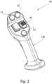
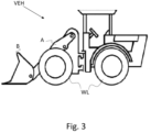
- Fig. 2 shows an example of a joystick JK implemented in work vehicles VEH for controlling an arm A and/or a bucket B, shown in figure 3 .
- the roller RL can be associated with the joystick lever, or it can be placed on the vehicle dashboard.
- buttons L1 - L3 can be implemented to allow the setting of some vehicle operating parameters. For example, they can be implemented to set the intervention thresholds of fans F1 - FN.
- the present invention can advantageously be carried out by means of a computer program which includes coding means for carrying out one or more steps of the method, when this program is executed on a computer. Therefore, it is understood that the scope of protection extends to said computer program and further to computer readable means comprising a recorded message, said computer readable means comprising program coding means for carrying out one or more steps of the method, when said program is executed on a computer.
Landscapes
- Engineering & Computer Science (AREA)
- Mining & Mineral Resources (AREA)
- Civil Engineering (AREA)
- General Engineering & Computer Science (AREA)
- Structural Engineering (AREA)
- Physics & Mathematics (AREA)
- Fluid Mechanics (AREA)
- Power Engineering (AREA)
- Operation Control Of Excavators (AREA)
Abstract
Hydraulic oil cooling control method for a fully electric work vehicle, the vehicle (VEH) including a hydraulic pump (P) for powering a hydraulic member (HF) via a hydraulic circuit (HC), an electric motor (ME) configured to drive the hydraulic pump in rotation, a radiator (HCR) equipped with a plurality of fans (F1,...,FN), a processing unit (VCU) configured to activate the electric motor in response to an activation of a human-machine interface device (JK, RL) and for the selective activation of a number of fans depending on a current temperature of the hydraulic oil circulating in the hydraulic circuit.
Description
- The present invention relates to the field of electric work vehicles, including the so-called Wheel Loaders, and agricultural vehicles and in particular to the methods and systems for controlling the cooling of hydraulic oil.
- Compact Wheel Loaders and Wheel Loaders are work vehicles equipped with an articulated arm to which a bucket is connected for moving material or for earthmoving. Some agricultural vehicles can also be equipped with similar arms and tools.
- What this category of vehicles, generically referred to as work vehicles, has in common is that they are entirely electrically powered. Therefore, they are not equipped with an internal combustion engine, but with a first electric propulsion motor that acts on at least one wheel without any hydrostat.
- However, electric work vehicles maintain the hydraulic circuit for actuating the arm and/or other work tools. This means that there is a hydraulic pump driven by a second electric motor, distinct and separate from the first electric motor. As long as no hydraulic tools are activated, the hydraulic pump remains deactivated to save electric energy.
- The hydraulic circuit generally includes at least one hydraulic actuator, generally a double action one, an open center directional control valve and a hydraulic oil recovery tank.
- The hydraulic oil, discharged into the recovery tank, is generally circulated through a radiator equipped with a plurality of cooling fans.
- According to the known technique, when a predetermined temperature threshold is exceeded, the fans are activated to cool the hydraulic oil.
- In electric work vehicles, the hydraulic pump and its second electric motor, which drives it in rotation, remain deactivated until at least one hydraulic tool is activated.
- This situation cannot be achieved by traditional vehicles equipped with an internal combustion engine, as in those vehicles the hydraulic pump is operationally connected to the drive shaft and is therefore always active, resulting in constant energy consumption.
- Generally, the articulated arm is controlled via a joystick. Other hydraulic devices can be controlled using levers, buttons or rollers.
- In electric work vehicles, as long as no human/machine interface device is operated by the operator, the hydraulic pump remains deactivated and therefore, the oil is not circulated in any way.
- In these vehicles, since the available energy is limited, it is essential to manage it optimally.
- Unless specifically excluded in the detailed description that follows, what is described in this chapter is to be considered as an integral part of the detailed description.
- The purpose of this solution is to improve the energy management of an electric work vehicle in connection with the cooling of the hydraulic oil driving at least one work component.
- The basic idea of the present invention is to control the selective switching on of the cooling fans associated with the hydraulic oil radiator as a function of the current temperature value of the hydraulic oil itself, taking into account the state of charge of the vehicle batteries and the state activation of the hydraulic pump associated with the hydraulic circuit.
- Preferably, when the state of charge of the vehicle batteries is higher than a predetermined threshold, as the temperature of the hydraulic oil increases, the number of active fans associated with the hydraulic oil radiator is gradually increased. Furthermore, as the temperature of the hydraulic oil decreases, the number of active fans associated with the radiator is gradually reduced.
- Preferably, the temperature threshold at which the last fan is deactivated is lower than the temperature threshold at which the first fan is activated so as to achieve hysteretic behavior.
- The dependent claims describe preferred variants of the invention, forming an integral part of the present description.
- Further objects and advantages of the present invention will be clear from the following detailed description of an example of its implementation (and its variants) and from the attached drawings given purely for explanatory and non-limiting purposes, in which:
-
Fig. 1 a hydraulic circuit diagram of a fully electric work vehicle controlled according to the present invention is shown; -
Fig. 2 shows a joystick for controlling an articulated arm of the work vehicle offigure 1 ; -
Fig. 3 shows an example of a work vehicle implementing the method of the present invention. - The same reference numbers and letters in the figures identify the same elements or components or functions.
- It should also be noted that the terms "first", "second", "third", "higher", "lower" and the like may be used here to distinguish various elements. These terms do not imply a spatial, sequential, or hierarchical order for the modified elements unless specifically indicated or inferred from the text.
- The elements and characteristics illustrated in the different preferred embodiments, including the drawings, can be combined with each other without departing from the scope of protection of the present application as described below.
- The present invention proposes a continuous control method performed on the hydraulic oil cooling system of a fully electric work vehicle VEH, such as for example a large (Wheel loader) or small (Compact Wheel Loader) mechanical loader.
- The vehicle VEH comprises an electro-hydraulic circuit HC comprising a hydraulic pump P to power a hydraulic member HF, an electric motor ME configured to drive the hydraulic pump in rotation, a radiator HCR equipped with a plurality of fans F1,...,FN for cooling the hydraulic oil circulating in the circuit.
- The circuit generally also includes a hydraulic oil recovery tank T.
- The recovery tank T is associated with a temperature sensor S, appropriately interfaced with a processing unit VCU.
- In the block HF it is meant the presence of at least one hydraulic member, such as for example an arm or a bucket, operated by a respective at least one hydraulic actuator, generally double action type.
- Furthermore, again in the block HF it is meant that there is at least one open center directional valve, for the control of the same at least one hydraulic actuator.
- The processing unit VCU receives as input the signals generated by human/machine interface devices, such as for example a joystick JK or a lever or a roller RL and is configured to activate the electric motor in response to an action performed by an operator on one of the interface devices.
- The activation of the electric motor ME causes the activation of the hydraulic pump P, with fixed geometry, which begins to pump hydraulic oil into the hydraulic circuit through at least one of the directional valves included in the block HF.
- The processing unit is configured to deactivate the electric motor in response to a release of the human-machine interface device. In other words, when the operator releases the joystick JK lever LJK or the roller RL, they are configured to return to a rest position.
- And in such rest position of the joystick lever or the roller, the processing unit is configured to generate a control signal, which indicates
- Stopping the electric motor
- The return of the corresponding directional valve to a corresponding rest position.
- Each of the directional valves is configured to distribute the hydraulic oil pumped by the hydraulic pump P between a respective hydraulic actuator and the recovery tank according to the deflection of the joystick lever or wheel with respect to the respective rest position. In particular, when the lever or wheel is fully operated, i.e. at maximum deflection compared to the rest condition, the entire flow of the hydraulic oil from the hydraulic pump P which reaches the corresponding directional valve is sent to the corresponding hydraulic actuator.
- A radiator is arranged between at least one directional valve and the recovery tank T. Its purpose is to maintain the temperature of the hydraulic oil below a predetermined temperature threshold, generally set at 90°C.
- A predetermined number of cooling fans are associated with the radiator. They are generally arranged close to each other in a plane parallel to the radiating surface of the radiator.
- For example, four fans can be provided, each associated with a portion of the radiating surface of the radiator. For example, if the radiator has a rectangular radiating surface, each portion can be identified by the axes of the rectangular surface.
- According to the present invention, the selective activation of a number of fans F1, F2, ... FN is envisaged as a function of a temperature of a hydraulic liquid circulating in the hydraulic circuit.
- For example, if there are four fans associated with the HCR hydraulic radiator, then turning on the fans can follow the scheme indicated in the following table:
HYDRAULIC OIL TEMPERATURE (°C) NUMBER OF ACTIVE FAN(S) 70 1 75 2 80 3 85 4 - When the first threshold Ts is exceeded, for example 70°C, a first fan is activated.
- When the second threshold is exceeded, for example 75°C, a second fan is activated.
- When the third threshold is exceeded, for example 80°C, a third fan is activated.
- When the fourth threshold is exceeded, for example 85°C, a fourth fan is activated.
- It can be derived that the selective activation of the number of fans is a function of the temperature of the hydraulic oil and more preferably, it is proportional to the temperature of the hydraulic oil, in the sense that as the temperature of the hydraulic oil increases, the number of active fans increases.
- Evidently, the same process can be performed in reverse, in the sense that when the temperature drops below the fourth threshold, one fan is turned off, leaving three remaining active, etc.
- Similarly, when the hydraulic oil temperature drops below the first threshold Ts, all fans are deactivated.
- Preferably, the temperature threshold Te at which the last fan is deactivated is lower than the temperature threshold Ts at which the first fan is activated (Te < Ts).
- Preferably, selective switching on of the number of fans is permitted only while at least one of the aforementioned human-machine interface devices, necessary for the activation of a hydraulic tool, is activated.
- Therefore, when, for example, the joystick lever is released, the electric motor is de-energized and the open-center directional valves are placed in closed conditions.
- Advantageously, this allows the consumption of electricity to be limited.
- According to another aspect of the invention, the state of charge of the vehicle batteries necessary to power the electric motor is continuously monitored and when the state of charge is lower than a predetermined threshold, for example, 10%, then the activation of any fan is inhibited.
- Preferably, when the state of charge is lower than said predetermined threshold, the rotation speed of the prime mover is limited so as to prevent a further increase in the temperature of the hydraulic oil and to provide the operator with the energy necessary for the return of the vehicle to a relevant charging station.
-
Fig. 2 shows an example of a joystick JK implemented in work vehicles VEH for controlling an arm A and/or a bucket B, shown infigure 3 . - The roller RL can be associated with the joystick lever, or it can be placed on the vehicle dashboard.
- The buttons L1 - L3 can be implemented to allow the setting of some vehicle operating parameters. For example, they can be implemented to set the intervention thresholds of fans F1 - FN.
- The present invention can advantageously be carried out by means of a computer program which includes coding means for carrying out one or more steps of the method, when this program is executed on a computer. Therefore, it is understood that the scope of protection extends to said computer program and further to computer readable means comprising a recorded message, said computer readable means comprising program coding means for carrying out one or more steps of the method, when said program is executed on a computer.
- Constructive variations to the non-limiting example described are possible, without departing from the scope of protection of the present invention, including all the equivalent embodiments for a person skilled in the art, to the contents of the claims.
- From the above description, the person skilled in the art is able to realize the object of the invention without introducing further construction details.
Claims (8)
- Hydraulic oil cooling control method for a fully electric work vehicle, the vehicle (VEH) including- a hydraulic pump (P) to power a hydraulic tool (HF) via a hydraulic circuit (HC),- an electric motor (ME) configured to drive the hydraulic pump in rotation,- a radiator (HCR) equipped with a plurality of fans (F1,...,FN),- a processing unit (VCU) configured to control at least one directional valve supplying the hydraulic tool (HF) and to activate the electric motor in response to an activation of a human-machine interface device (JK, RL) and for deactivating the electric motor in response to a release of the human-machine interface device, the method comprising a procedure of selectively activating a number of fans as a function of a current temperature of a hydraulic liquid circulating in the hydraulic circuit.
- The method according to claim 1, wherein said selective activation of the number of fans is permitted only while said human-machine interface device is activated.
- A method according to claim 1 or 2, wherein an activation of any fan is inhibited when a current value of a state of charge of vehicular batteries is lower than a predetermined threshold of the state of charge.
- Method according to claim 3, wherein said state of charge threshold is equal to 10%.
- Processing unit (VCU) configured to control at least one directional valve supplying a hydraulic tool (HF) of a fully electric work vehicle (VEH), the vehicle (VEH) comprising- a hydraulic pump (P) to power said hydraulic tool (HF) via a hydraulic circuit (HC),- an electric motor (ME) configured to drive the hydraulic pump in rotation,- a radiator (HCR) equipped with a plurality of fans (F1,...,FN),wherein the processing unit (VCU) is configured to activate the electric motor in response to an activation of a human-machine interface (JK, RL) device and to deactivate the electric motor in response to a release of the interface device man-machine, the unit being configured for the selective activation of a number of fans as a function of a current temperature of a hydraulic liquid circulating in the hydraulic circuit.
- Fully electric work vehicle (VEH), including- a hydraulic pump (P) to power a hydraulic tool (HF) via a hydraulic circuit (HC),- an electric motor (ME) configured to drive the hydraulic pump in rotation,- a radiator (HCR) equipped with a plurality of fans (F1,...,FN),- a processing unit (VCU) according to claim 5.
- A computer program comprising instructions for causing the processing unit of claim 5 to implement the procedure of the method according to claim 1.
- A computer readable medium having stored the program of claim 7.
Applications Claiming Priority (1)
| Application Number | Priority Date | Filing Date | Title |
|---|---|---|---|
| IT102023000026199A IT202300026199A1 (en) | 2023-12-06 | 2023-12-06 | HYDRAULIC OIL COOLING CONTROL METHOD AND SYSTEM FOR AN ALL-ELECTRIC WORK VEHICLE |
Publications (1)
| Publication Number | Publication Date |
|---|---|
| EP4567205A1 true EP4567205A1 (en) | 2025-06-11 |
Family
ID=89898072
Family Applications (1)
| Application Number | Title | Priority Date | Filing Date |
|---|---|---|---|
| EP24217651.9A Pending EP4567205A1 (en) | 2023-12-06 | 2024-12-05 | Hydraulic oil cooling control method and system for a fully electric work vehicle |
Country Status (2)
| Country | Link |
|---|---|
| EP (1) | EP4567205A1 (en) |
| IT (1) | IT202300026199A1 (en) |
Citations (2)
| Publication number | Priority date | Publication date | Assignee | Title |
|---|---|---|---|---|
| JP2021147859A (en) * | 2020-03-18 | 2021-09-27 | 住友建機株式会社 | Shovel |
| US20230151584A1 (en) * | 2020-02-27 | 2023-05-18 | Cnh Industrial America Llc | System and method for heating the hydraulic fluid of an electric work vehicle |
-
2023
- 2023-12-06 IT IT102023000026199A patent/IT202300026199A1/en unknown
-
2024
- 2024-12-05 EP EP24217651.9A patent/EP4567205A1/en active Pending
Patent Citations (2)
| Publication number | Priority date | Publication date | Assignee | Title |
|---|---|---|---|---|
| US20230151584A1 (en) * | 2020-02-27 | 2023-05-18 | Cnh Industrial America Llc | System and method for heating the hydraulic fluid of an electric work vehicle |
| JP2021147859A (en) * | 2020-03-18 | 2021-09-27 | 住友建機株式会社 | Shovel |
Also Published As
| Publication number | Publication date |
|---|---|
| IT202300026199A1 (en) | 2025-06-06 |
Similar Documents
| Publication | Publication Date | Title |
|---|---|---|
| JP6806409B2 (en) | Flood hybrid propulsion circuit with static pressure option and its operation method | |
| US8639422B2 (en) | Cooling system for hybrid working machine | |
| US12228067B2 (en) | Fan speed control system for engine cooling | |
| CN112004974A (en) | Electric working machine | |
| US10399572B2 (en) | Hydraulic hybrid propel circuit with hydrostatic option and method of operation | |
| KR101286843B1 (en) | Hybrid construction machine control system | |
| EP3009689B1 (en) | Hydraulic system of a vehicle | |
| EP2930077B1 (en) | Vehicle equipped with a hydraulically-operated device | |
| JP2005257064A (en) | Method of controlling heavy loading work device in emergency | |
| US11884136B2 (en) | System and method for idle mitigation on a utility truck with an electrically isolated hydraulically controlled aerial work platform | |
| JP6366981B2 (en) | Excavator | |
| CN112429642B (en) | Hydraulic auxiliary driving control system and method for getting on double-engine crane and crane | |
| US12601148B2 (en) | Electric work vehicle with power conserving work component subsystem preconditioning | |
| JP7458842B2 (en) | excavator | |
| JP2012158890A (en) | Drive control device for working machine | |
| EP3178778B1 (en) | Hydraulic system for energy regeneration and industrial truck with said hydraulic system | |
| CN103863104B (en) | A kind of caterpillar and its power drive system and method | |
| CN118715390A (en) | Device and method for controlling an electrohydraulic transmission | |
| EP4461621B1 (en) | Method for managing a hydraulic circuit of an electric work vehicle | |
| IT202300026199A1 (en) | HYDRAULIC OIL COOLING CONTROL METHOD AND SYSTEM FOR AN ALL-ELECTRIC WORK VEHICLE | |
| CN113685541A (en) | Hydrostatic drive | |
| JPH0556519U (en) | Hydraulically driven air cooler for vehicles |
Legal Events
| Date | Code | Title | Description |
|---|---|---|---|
| PUAI | Public reference made under article 153(3) epc to a published international application that has entered the european phase |
Free format text: ORIGINAL CODE: 0009012 |
|
| STAA | Information on the status of an ep patent application or granted ep patent |
Free format text: STATUS: THE APPLICATION HAS BEEN PUBLISHED |
|
| AK | Designated contracting states |
Kind code of ref document: A1 Designated state(s): AL AT BE BG CH CY CZ DE DK EE ES FI FR GB GR HR HU IE IS IT LI LT LU LV MC ME MK MT NL NO PL PT RO RS SE SI SK SM TR |
|
| STAA | Information on the status of an ep patent application or granted ep patent |
Free format text: STATUS: REQUEST FOR EXAMINATION WAS MADE |
|
| 17P | Request for examination filed |
Effective date: 20251211 |