EP4567199A1 - Construction equipment - Google Patents
Construction equipment Download PDFInfo
- Publication number
- EP4567199A1 EP4567199A1 EP23930600.4A EP23930600A EP4567199A1 EP 4567199 A1 EP4567199 A1 EP 4567199A1 EP 23930600 A EP23930600 A EP 23930600A EP 4567199 A1 EP4567199 A1 EP 4567199A1
- Authority
- EP
- European Patent Office
- Prior art keywords
- fuel cell
- inclination angle
- electric power
- electrically driven
- battery
- Prior art date
- Legal status (The legal status is an assumption and is not a legal conclusion. Google has not performed a legal analysis and makes no representation as to the accuracy of the status listed.)
- Pending
Links
Images


Classifications
-
- E—FIXED CONSTRUCTIONS
- E02—HYDRAULIC ENGINEERING; FOUNDATIONS; SOIL SHIFTING
- E02F—DREDGING; SOIL-SHIFTING
- E02F9/00—Component parts of dredgers or soil-shifting machines, not restricted to one of the kinds covered by groups E02F3/00 - E02F7/00
- E02F9/20—Drives; Control devices
- E02F9/2058—Electric or electro-mechanical or mechanical control devices of vehicle sub-units
- E02F9/2091—Control of energy storage means for electrical energy, e.g. battery or capacitors
-
- B—PERFORMING OPERATIONS; TRANSPORTING
- B60—VEHICLES IN GENERAL
- B60L—PROPULSION OF ELECTRICALLY-PROPELLED VEHICLES; SUPPLYING ELECTRIC POWER FOR AUXILIARY EQUIPMENT OF ELECTRICALLY-PROPELLED VEHICLES; ELECTRODYNAMIC BRAKE SYSTEMS FOR VEHICLES IN GENERAL; MAGNETIC SUSPENSION OR LEVITATION FOR VEHICLES; MONITORING OPERATING VARIABLES OF ELECTRICALLY-PROPELLED VEHICLES; ELECTRIC SAFETY DEVICES FOR ELECTRICALLY-PROPELLED VEHICLES
- B60L50/00—Electric propulsion with power supplied within the vehicle
- B60L50/50—Electric propulsion with power supplied within the vehicle using propulsion power supplied by batteries or fuel cells
- B60L50/75—Electric propulsion with power supplied within the vehicle using propulsion power supplied by batteries or fuel cells using propulsion power supplied by both fuel cells and batteries
-
- B—PERFORMING OPERATIONS; TRANSPORTING
- B60—VEHICLES IN GENERAL
- B60L—PROPULSION OF ELECTRICALLY-PROPELLED VEHICLES; SUPPLYING ELECTRIC POWER FOR AUXILIARY EQUIPMENT OF ELECTRICALLY-PROPELLED VEHICLES; ELECTRODYNAMIC BRAKE SYSTEMS FOR VEHICLES IN GENERAL; MAGNETIC SUSPENSION OR LEVITATION FOR VEHICLES; MONITORING OPERATING VARIABLES OF ELECTRICALLY-PROPELLED VEHICLES; ELECTRIC SAFETY DEVICES FOR ELECTRICALLY-PROPELLED VEHICLES
- B60L58/00—Methods or circuit arrangements for monitoring or controlling batteries or fuel cells, specially adapted for electric vehicles
- B60L58/40—Methods or circuit arrangements for monitoring or controlling batteries or fuel cells, specially adapted for electric vehicles for controlling a combination of batteries and fuel cells
-
- E—FIXED CONSTRUCTIONS
- E02—HYDRAULIC ENGINEERING; FOUNDATIONS; SOIL SHIFTING
- E02F—DREDGING; SOIL-SHIFTING
- E02F9/00—Component parts of dredgers or soil-shifting machines, not restricted to one of the kinds covered by groups E02F3/00 - E02F7/00
-
- E—FIXED CONSTRUCTIONS
- E02—HYDRAULIC ENGINEERING; FOUNDATIONS; SOIL SHIFTING
- E02F—DREDGING; SOIL-SHIFTING
- E02F9/00—Component parts of dredgers or soil-shifting machines, not restricted to one of the kinds covered by groups E02F3/00 - E02F7/00
- E02F9/08—Superstructures; Supports for superstructures
- E02F9/0858—Arrangement of component parts installed on superstructures not otherwise provided for, e.g. electric components, fenders, air-conditioning units
-
- E—FIXED CONSTRUCTIONS
- E02—HYDRAULIC ENGINEERING; FOUNDATIONS; SOIL SHIFTING
- E02F—DREDGING; SOIL-SHIFTING
- E02F9/00—Component parts of dredgers or soil-shifting machines, not restricted to one of the kinds covered by groups E02F3/00 - E02F7/00
- E02F9/20—Drives; Control devices
- E02F9/2058—Electric or electro-mechanical or mechanical control devices of vehicle sub-units
- E02F9/2062—Control of propulsion units
- E02F9/207—Control of propulsion units of the type electric propulsion units, e.g. electric motors or generators
-
- E—FIXED CONSTRUCTIONS
- E02—HYDRAULIC ENGINEERING; FOUNDATIONS; SOIL SHIFTING
- E02F—DREDGING; SOIL-SHIFTING
- E02F9/00—Component parts of dredgers or soil-shifting machines, not restricted to one of the kinds covered by groups E02F3/00 - E02F7/00
- E02F9/20—Drives; Control devices
- E02F9/2058—Electric or electro-mechanical or mechanical control devices of vehicle sub-units
- E02F9/2062—Control of propulsion units
- E02F9/2075—Control of propulsion units of the hybrid type
-
- H—ELECTRICITY
- H01—ELECTRIC ELEMENTS
- H01M—PROCESSES OR MEANS, e.g. BATTERIES, FOR THE DIRECT CONVERSION OF CHEMICAL ENERGY INTO ELECTRICAL ENERGY
- H01M16/00—Structural combinations of different types of electrochemical generators
- H01M16/003—Structural combinations of different types of electrochemical generators of fuel cells with other electrochemical devices, e.g. capacitors, electrolysers
- H01M16/006—Structural combinations of different types of electrochemical generators of fuel cells with other electrochemical devices, e.g. capacitors, electrolysers of fuel cells with rechargeable batteries
-
- B—PERFORMING OPERATIONS; TRANSPORTING
- B60—VEHICLES IN GENERAL
- B60L—PROPULSION OF ELECTRICALLY-PROPELLED VEHICLES; SUPPLYING ELECTRIC POWER FOR AUXILIARY EQUIPMENT OF ELECTRICALLY-PROPELLED VEHICLES; ELECTRODYNAMIC BRAKE SYSTEMS FOR VEHICLES IN GENERAL; MAGNETIC SUSPENSION OR LEVITATION FOR VEHICLES; MONITORING OPERATING VARIABLES OF ELECTRICALLY-PROPELLED VEHICLES; ELECTRIC SAFETY DEVICES FOR ELECTRICALLY-PROPELLED VEHICLES
- B60L2200/00—Type of vehicles
- B60L2200/40—Working vehicles
-
- B—PERFORMING OPERATIONS; TRANSPORTING
- B60—VEHICLES IN GENERAL
- B60L—PROPULSION OF ELECTRICALLY-PROPELLED VEHICLES; SUPPLYING ELECTRIC POWER FOR AUXILIARY EQUIPMENT OF ELECTRICALLY-PROPELLED VEHICLES; ELECTRODYNAMIC BRAKE SYSTEMS FOR VEHICLES IN GENERAL; MAGNETIC SUSPENSION OR LEVITATION FOR VEHICLES; MONITORING OPERATING VARIABLES OF ELECTRICALLY-PROPELLED VEHICLES; ELECTRIC SAFETY DEVICES FOR ELECTRICALLY-PROPELLED VEHICLES
- B60L2240/00—Control parameters of input or output; Target parameters
- B60L2240/40—Drive Train control parameters
- B60L2240/54—Drive Train control parameters related to batteries
-
- B—PERFORMING OPERATIONS; TRANSPORTING
- B60—VEHICLES IN GENERAL
- B60L—PROPULSION OF ELECTRICALLY-PROPELLED VEHICLES; SUPPLYING ELECTRIC POWER FOR AUXILIARY EQUIPMENT OF ELECTRICALLY-PROPELLED VEHICLES; ELECTRODYNAMIC BRAKE SYSTEMS FOR VEHICLES IN GENERAL; MAGNETIC SUSPENSION OR LEVITATION FOR VEHICLES; MONITORING OPERATING VARIABLES OF ELECTRICALLY-PROPELLED VEHICLES; ELECTRIC SAFETY DEVICES FOR ELECTRICALLY-PROPELLED VEHICLES
- B60L2240/00—Control parameters of input or output; Target parameters
- B60L2240/60—Navigation input
- B60L2240/64—Road conditions
- B60L2240/642—Slope of road
-
- B—PERFORMING OPERATIONS; TRANSPORTING
- B60—VEHICLES IN GENERAL
- B60L—PROPULSION OF ELECTRICALLY-PROPELLED VEHICLES; SUPPLYING ELECTRIC POWER FOR AUXILIARY EQUIPMENT OF ELECTRICALLY-PROPELLED VEHICLES; ELECTRODYNAMIC BRAKE SYSTEMS FOR VEHICLES IN GENERAL; MAGNETIC SUSPENSION OR LEVITATION FOR VEHICLES; MONITORING OPERATING VARIABLES OF ELECTRICALLY-PROPELLED VEHICLES; ELECTRIC SAFETY DEVICES FOR ELECTRICALLY-PROPELLED VEHICLES
- B60L3/00—Electric devices on electrically-propelled vehicles for safety purposes; Monitoring operating variables, e.g. speed, deceleration or energy consumption
- B60L3/0023—Detecting, eliminating, remedying or compensating for drive train abnormalities, e.g. failures within the drive train
- B60L3/0053—Detecting, eliminating, remedying or compensating for drive train abnormalities, e.g. failures within the drive train relating to fuel cells
-
- B—PERFORMING OPERATIONS; TRANSPORTING
- B60—VEHICLES IN GENERAL
- B60L—PROPULSION OF ELECTRICALLY-PROPELLED VEHICLES; SUPPLYING ELECTRIC POWER FOR AUXILIARY EQUIPMENT OF ELECTRICALLY-PROPELLED VEHICLES; ELECTRODYNAMIC BRAKE SYSTEMS FOR VEHICLES IN GENERAL; MAGNETIC SUSPENSION OR LEVITATION FOR VEHICLES; MONITORING OPERATING VARIABLES OF ELECTRICALLY-PROPELLED VEHICLES; ELECTRIC SAFETY DEVICES FOR ELECTRICALLY-PROPELLED VEHICLES
- B60L50/00—Electric propulsion with power supplied within the vehicle
- B60L50/50—Electric propulsion with power supplied within the vehicle using propulsion power supplied by batteries or fuel cells
- B60L50/70—Electric propulsion with power supplied within the vehicle using propulsion power supplied by batteries or fuel cells using power supplied by fuel cells
- B60L50/72—Constructional details of fuel cells specially adapted for electric vehicles
-
- B—PERFORMING OPERATIONS; TRANSPORTING
- B60—VEHICLES IN GENERAL
- B60Y—INDEXING SCHEME RELATING TO ASPECTS CROSS-CUTTING VEHICLE TECHNOLOGY
- B60Y2200/00—Type of vehicle
- B60Y2200/40—Special vehicles
- B60Y2200/41—Construction vehicles, e.g. graders, excavators
- B60Y2200/412—Excavators
-
- H—ELECTRICITY
- H01—ELECTRIC ELEMENTS
- H01M—PROCESSES OR MEANS, e.g. BATTERIES, FOR THE DIRECT CONVERSION OF CHEMICAL ENERGY INTO ELECTRICAL ENERGY
- H01M2250/00—Fuel cells for particular applications; Specific features of fuel cell system
- H01M2250/20—Fuel cells in motive systems, e.g. vehicle, ship, plane
-
- Y—GENERAL TAGGING OF NEW TECHNOLOGICAL DEVELOPMENTS; GENERAL TAGGING OF CROSS-SECTIONAL TECHNOLOGIES SPANNING OVER SEVERAL SECTIONS OF THE IPC; TECHNICAL SUBJECTS COVERED BY FORMER USPC CROSS-REFERENCE ART COLLECTIONS [XRACs] AND DIGESTS
- Y02—TECHNOLOGIES OR APPLICATIONS FOR MITIGATION OR ADAPTATION AGAINST CLIMATE CHANGE
- Y02E—REDUCTION OF GREENHOUSE GAS [GHG] EMISSIONS, RELATED TO ENERGY GENERATION, TRANSMISSION OR DISTRIBUTION
- Y02E60/00—Enabling technologies; Technologies with a potential or indirect contribution to GHG emissions mitigation
- Y02E60/30—Hydrogen technology
- Y02E60/50—Fuel cells
Definitions
- the present invention relates to a construction machine mounted with a fuel cell.
- Patent Document 1 discloses a fuel cell vehicle including a fuel cell system and an exhaust structure for discharging, to the outside of the vehicle, a cathode exhaust gas that flows out from the fuel cell system.
- the exhaust structure includes a main exhaust pipe having a straddling portion straddling a vehicle structure member thereabove and extending from one side to the other side in the horizontal, and a water bleeding bypass pipe disposed below the vehicle structure member, branching from the main exhaust pipe at a position on the one side in the horizontal direction relative to the vehicle structure member, and connected to the main exhaust pipe at a position on the other side in the horizontal direction relative to the vehicle structure member, the water bleeding bypass pipe being thinner than the main exhaust pipe.
- the present invention has been made in view of the above problems. It is an object of the present invention to provide a construction machine that is able to prevent the water generated in the process of generating electric power by a fuel cell from being left undrained even when the machine body of the construction machine is inclined.
- a construction machine includes a machine body, an electrically driven motor as a power source, a fuel cell that generates electric power to be supplied to the electrically driven motor, a battery that stores the electric power generated by the fuel cell, an inclination angle sensor that senses an inclination of the machine body, and a controller, in which the controller is configured to switch supplying of the electric power to the electrically driven motor from the fuel cell to the battery when a sensing result from the inclination angle sensor is equal to or larger than a predetermined inclination angle threshold.
- the water generated in the process of generating electric power by the fuel cell is prevented from being left undrained.
- FIG. 1 schematically illustrates, in a side elevation, the appearance of a hydraulic excavator as an example of construction machine according to the present embodiment.
- FIG. 2 schematically illustrates, in functional block form, a power supply system, which includes a fuel cell, of the hydraulic excavator together with related configurations.
- a hydraulic excavator 100 essentially includes a machine body 1B (main construction machine body) made up of a crawler type lower track structure 1e and an upper swing structure 1d swingably mounted on the lower track structure 1e, and a work device 1A (front work implement) elevatably mounted on a front side of the upper swing structure 1d.
- a machine body 1B main construction machine body
- a work device 1A front work implement
- the upper swing structure 1d includes a swing frame as a base with various members disposed thereon.
- the upper swing structure 1d is swingable with respect to the lower track structure 1e by being swing-driven with respect to the lower track structure 1e by the hydraulic swing motor, not depicted, as a hydraulic actuator.
- a fuel cell 1 that generates electric power for driving the hydraulic excavator 100
- a secondary battery 6 battery that stores the electric power generated by the fuel cell 1
- an inclination angle sensor 10 that senses the inclination (gradient, sloping direction) of the machine body 1B of the hydraulic excavator 100
- an electrically driven motor 4 that is driven by the electric power from the fuel cell 1 and the secondary battery 6,
- a hydraulic drive system 5 for driving hydraulic actuators including a hydraulic pump and a pilot pump that are driven by the electrically driven motor 4, and a controller 9 that controls the action of the hydraulic excavator 100 in its entirety.
- the fuel cell 1 is a device for generating electric power from a chemical reaction between a fuel (e.g., hydrogen) and an oxidizer (e.g., oxygen).
- a fuel e.g., hydrogen
- an oxidizer e.g., oxygen
- air that contains oxygen (oxidizer) required to react with hydrogen (fuel) is sent into the inside of the fuel cell by an electrically driven compressor, and the air whose oxygen has been consumed by the reaction and water generated by the reaction (generated water) are discharged via an air/water drain pipe 12.
- the fuel cell 1 is driving in a normal state, e.g., where the fuel cell 1 is generating electric power to meet the demand from the electrically driven motor 4, the generated water is expelled from the air/water drain pipe 12 under the pressure of the discharged air that has been sent in by the electrically driven compressor and whose oxygen has been consumed.
- the amount of consumed oxygen varies, and thus the amount of air sent in by the electrically driven compressor varies.
- the amount of air sent in increases.
- the amount of air sent in by the electrically driven compressor is maximized.
- the amount of air discharged from the air/water drain pipe 12 is also maximized, and the amount of water generated in the process of generating electric power by the fuel cell 1 and the water draining capability thereof are also maximized.
- the amount of air sent in decreases, and when the fuel cell 1 is driving in a prescribed low-idling state (low-load state) where the fuel cell 1 is in an electric power generation standby state, the amount of air sent in by the electrically driven compressor is minimized.
- the amount of air discharged from the air/water drain pipe 12 is also minimized, and the amount of water generated in the process of generating electric power by the fuel cell 1 and the water draining capability are also minimized.
- the electric power generation standby state means a state where the fuel cell 1 is steadily driving with an amount of electric power generation of approximately 10kW in order to immediately generate electric power for meeting electric power demands while taking into consideration the fact that it takes considerable amount of time for the fuel cell 1 to generate a sufficient level of electric power from level zero.
- the fuel cell 1 With the fuel cell 1 kept in the electric power generation standby state when it is not required to supply electric power from the fuel cell 1, the fuel cell 1 is able to generate electric power immediately to supply demanded electric power to meet all electric power demands from the hydraulic excavator 100, for example, when there is an input operation from an operating lever, when a motor rotational speed adjusting dial inputs a command for increasing the rotational speed, when an air conditioner is turned on, when LIB is charged, and when the water generated by the fuel cell 1 is purged.
- the fuel cell 1 in a power supply system of the hydraulic excavator 100, the fuel cell 1 generates electric power in response to a control signal from the controller 9 and supplies the generated electric power via a DC/DC converter 2 to an inverter 3 and the secondary battery 6 (battery).
- the secondary battery 6 supplies stored electric power to the inverter 3 via a bidirectional DC/DC converter 7 that operates in response to a control signal from the controller 9, and stores electric power supplied from the fuel cell 1 via the DC/DC converter 2.
- the secondary battery 6 is provided with an SOC sensor 8 that senses a state of charge (SOC) thereof, and the SOC sensor 8 sends a sensing result to the controller 9.
- SOC state of charge
- the inverter 3 In response to a control signal from the controller 9, the inverter 3 converts the electric power supplied from fuel cell 1 and the secondary battery 6 and drives the electrically driven motor 4 with the converted electric power.
- the controller 9 performs a power supply operation control process for controlling the operation of the power supply system including the fuel cell 1 and the secondary battery 6 (i.e., the bidirectional DC/DC converter 7) depending on operating signals from levers and an operation console 11 including key switches installed in a cabin disposed on a front portion of the upper swing structure 1d and sensing results from the SOC sensor 8 and the inclination angle sensor 10.
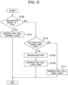
- FIG. 3 is a flowchart illustrating details of the power supply operation control process.
- the controller 9 initially determines whether the sensing result from the inclination angle sensor 10, i.e., the inclination angle ⁇ of the machine body 1B, is smaller than a predetermined inclination angle threshold ⁇ th (step S100).
- the inclination angle threshold ⁇ th is a threshold with which to determine whether the inclination angle of the machine body 1B, or stated otherwise, the inclination angle of the fuel cell 1, is an angle at which the generated water can sufficiently be drained by the water draining capability of the fuel cell 1 in the electric power generation standby state.
- step S100 determines whether the state of charge of the secondary battery 6 is larger than a lower-limit SOC (state-of-charge threshold) (step S110).
- the lower-limit SOC is a criterion with which to determine whether the secondary battery 6 has an enough power storage ratio not disrupting the supply of electric power to the members of the hydraulic excavator 100.
- step S110 If the determined result in step S110 is YES, then the electrically driven motor 4 is switched to be driven by the electric power from the secondary battery 6, i.e., a battery-driven state, (step S120), and the fuel cell 1 is switched to the electric power generation standby state (low-load state) (step S130). That is, in the series of processing of steps S100, S110, S120, and S130, while the fuel cell 1 is in the state (inclination angle) where it is unable to sufficiently drain the generated water, control is performed such that the fuel cell 1 drives in the low-load state and the amount of generated water is minimized to reduce the need for water drainage, and that the hydraulic excavator 100 is driven with the electric power from the secondary battery 6 that is in the sufficient state of charge.
- step S111 the fuel cell 1 drives in the high-load state (step S111). That is, in the series of processing of steps S100, S110, and S111, while the fuel cell 1 is in the state (inclination angle) where it is unable to sufficiently drain the generated water, if the hydraulic excavator 100 cannot be driven by the electric power from the secondary battery 6, then control is performed such that the fuel cell 1 drives in the high-load state to maximize the water draining capability thereof and hence to drain the generated water sufficiently, and that the secondary battery 6 is charged.
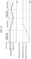
- FIG. 4 is a diagram illustrating an example of time-depending changes in the state of charge of the secondary battery and the machine body inclination angle in the power supply operation control process.
- the hydraulic excavator 100 is driven by the electric power generated by the fuel cell 1 driving in the normal state. At this time, the state of charge of the secondary battery 6 keeps a maximum value (upper-limit SOC).
- the fuel cell 1 is switched to the electric power generation standby state to restrain the generation of water, and the hydraulic excavator 100 is switched to be driven with the electric power from the secondary battery 6.
- the maximum inclination angle ⁇ max means a maximum value of the inclination angle of the machine body at which the construction machine is required to be workable, and represents 35 degrees in all directions of the machine body, for example.
- the hydraulic excavator 100 When the hydraulic excavator 100 is continuously driven in the state where the inclination angle of the machine body is the maximum inclination angle ⁇ max until the state of charge of the secondary battery 6 reaches its lower limit value (lower-limit SOC), the hydraulic excavator 100 is switched to be driven with the electric power generated by the fuel cell 1 in the high-load state, and the secondary battery 6 is charged.
- the state of charge of the secondary battery 6 reaches a predetermined intermediate SOC
- the fuel cell 1 is switched again to the electric power generation standby state to restrain the generation of water, and the hydraulic excavator 100 is switched to be driven with the electric power from the secondary battery 6.
- the hydraulic excavator 100 is immediately switched from being driven by the fuel cell 1 to be driven by the secondary battery 6.
- the present invention is not limited to such details, but the hydraulic excavator 100 may be immediately switched to be driven by the secondary battery 6 upon elapse of a preset period of time after the sensing result from the inclination angle sensor 10 has reached the inclination angle threshold ⁇ th.
- the present invention is not limited to the embodiment described above, but covers various modifications and combinations without departing from the scope thereof. Moreover, the present invention is not limited to anything that includes all the structural details described according to the above embodiment, but covers anything that includes some of the structural details.
- the structural details and functions described above may be realized in part or entirely by being designed with integrated circuits, for example. Moreover, the structural details and functions described above may be software-implemented by a processor that interprets and executes programs representing the functions.
Landscapes
- Engineering & Computer Science (AREA)
- Mining & Mineral Resources (AREA)
- Sustainable Development (AREA)
- Sustainable Energy (AREA)
- Life Sciences & Earth Sciences (AREA)
- Structural Engineering (AREA)
- General Engineering & Computer Science (AREA)
- Civil Engineering (AREA)
- Power Engineering (AREA)
- Transportation (AREA)
- Mechanical Engineering (AREA)
- General Chemical & Material Sciences (AREA)
- Electrochemistry (AREA)
- Chemical Kinetics & Catalysis (AREA)
- Chemical & Material Sciences (AREA)
- Operation Control Of Excavators (AREA)
- Fuel Cell (AREA)
Abstract
Description
- The present invention relates to a construction machine mounted with a fuel cell.
- Fuel cells mounted on construction machines such as hydraulic excavators are required to appropriately drain the water generated in their process of generating electric energy. As a technology regarding water drainage, Patent Document 1, for example, discloses a fuel cell vehicle including a fuel cell system and an exhaust structure for discharging, to the outside of the vehicle, a cathode exhaust gas that flows out from the fuel cell system. The exhaust structure includes a main exhaust pipe having a straddling portion straddling a vehicle structure member thereabove and extending from one side to the other side in the horizontal, and a water bleeding bypass pipe disposed below the vehicle structure member, branching from the main exhaust pipe at a position on the one side in the horizontal direction relative to the vehicle structure member, and connected to the main exhaust pipe at a position on the other side in the horizontal direction relative to the vehicle structure member, the water bleeding bypass pipe being thinner than the main exhaust pipe.
- Patent Document 1:
JP-2019-217895-A - Work sites where construction machines operate include sloping terrains that have various gradients and sloping directions. In addition, construction machines may be required to work on slopes whose gradients are too large to consider using general automobiles thereon. Consequently, the prior art referred to above may encounter a situation in which the generated water tends to be left undrained depending on the degree of inclination of the machine body. However, if the water generated by the fuel cell remains undrained, then it may adversely affect the operation state of the fuel cell and may cause damage to a water draining mechanism when the generated water is frozen.
- The present invention has been made in view of the above problems. It is an object of the present invention to provide a construction machine that is able to prevent the water generated in the process of generating electric power by a fuel cell from being left undrained even when the machine body of the construction machine is inclined.
- The present application includes a plurality of means for solving the above problems. According to an example of those, a construction machine includes a machine body, an electrically driven motor as a power source, a fuel cell that generates electric power to be supplied to the electrically driven motor, a battery that stores the electric power generated by the fuel cell, an inclination angle sensor that senses an inclination of the machine body, and a controller, in which the controller is configured to switch supplying of the electric power to the electrically driven motor from the fuel cell to the battery when a sensing result from the inclination angle sensor is equal to or larger than a predetermined inclination angle threshold.
- According to the present invention, even when the machine body is inclined, the water generated in the process of generating electric power by the fuel cell is prevented from being left undrained.
-
-
FIG. 1 is a side elevational view schematically illustrating the appearance of a hydraulic excavator as an example of construction machine. -
FIG. 2 is a functional block diagram schematically illustrating a power supply system, which includes a fuel cell, of the hydraulic excavator together with related configurations. -
FIG. 3 is a flowchart illustrating details of a power supply operation control process. -
FIG. 4 is a diagram illustrating an example of time-depending changes in the state of charge of a secondary battery and in a machine body inclination angle in the power supply operation control process. - An embodiment of the present invention will be described hereinbelow with reference to the drawings. While a hydraulic excavator will be described as an example of construction machine in the embodiment, the present invention is also applicable to any of other construction machines each of which is mounted with a fuel cell.
-
FIG. 1 schematically illustrates, in a side elevation, the appearance of a hydraulic excavator as an example of construction machine according to the present embodiment.FIG. 2 schematically illustrates, in functional block form, a power supply system, which includes a fuel cell, of the hydraulic excavator together with related configurations. - As illustrated in
FIG. 1 , ahydraulic excavator 100, essentially includes amachine body 1B (main construction machine body) made up of a crawler typelower track structure 1e and anupper swing structure 1d swingably mounted on thelower track structure 1e, and awork device 1A (front work implement) elevatably mounted on a front side of theupper swing structure 1d. - The
work device 1a includes a multi-joint front work implement including a plurality of driven members (aboom 1a, anarm 1b, and abucket 1c) each rotates in vertical directions. Theboom 1a has a proximal end rotatably supported in upward and downward directions on the front side of theupper swing structure 1d. Theboom 1a has a distal end to which one end of thearm 1b is rotatably coupled in upward and downward directions. Thebucket 1c is rotatably coupled in upward and downward directions to the other end (distal end) of thearm 1b. Theboom 1a, thearm 1b, and thebucket 1c are driven respectively by a boom cylinder, an arm cylinder, and a bucket cylinder provided as hydraulic actuators, not depicted. - The
upper swing structure 1d includes a swing frame as a base with various members disposed thereon. Theupper swing structure 1d is swingable with respect to thelower track structure 1e by being swing-driven with respect to thelower track structure 1e by the hydraulic swing motor, not depicted, as a hydraulic actuator. On the swing frame of theupper swing structure 1d, there are mounted a fuel cell 1 that generates electric power for driving thehydraulic excavator 100, a secondary battery 6 (battery) that stores the electric power generated by the fuel cell 1, aninclination angle sensor 10 that senses the inclination (gradient, sloping direction) of themachine body 1B of thehydraulic excavator 100, an electrically drivenmotor 4 that is driven by the electric power from the fuel cell 1 and thesecondary battery 6, ahydraulic drive system 5 for driving hydraulic actuators including a hydraulic pump and a pilot pump that are driven by the electrically drivenmotor 4, and acontroller 9 that controls the action of thehydraulic excavator 100 in its entirety. - The fuel cell 1 is a device for generating electric power from a chemical reaction between a fuel (e.g., hydrogen) and an oxidizer (e.g., oxygen). In the fuel cell 1 according to the present embodiment, air that contains oxygen (oxidizer) required to react with hydrogen (fuel) is sent into the inside of the fuel cell by an electrically driven compressor, and the air whose oxygen has been consumed by the reaction and water generated by the reaction (generated water) are discharged via an air/
water drain pipe 12. - Where the fuel cell 1 is driving in a normal state, e.g., where the fuel cell 1 is generating electric power to meet the demand from the electrically driven
motor 4, the generated water is expelled from the air/water drain pipe 12 under the pressure of the discharged air that has been sent in by the electrically driven compressor and whose oxygen has been consumed. Depending on the driving condition (whether the amount of generated electric power increases or decreases) of the fuel cell 1, the amount of consumed oxygen varies, and thus the amount of air sent in by the electrically driven compressor varies. - For example, with increase in the amount of electric power generated by the fuel cell 1, the amount of air sent in (and the amount of discharged air) increases. Where the fuel cell 1 is driving in a prescribed high-load state where the fuel cell 1 generates more electric power than in the normal state, the amount of air sent in by the electrically driven compressor is maximized. At this time, the amount of air discharged from the air/
water drain pipe 12 is also maximized, and the amount of water generated in the process of generating electric power by the fuel cell 1 and the water draining capability thereof are also maximized. - Similarly, with decrease in the amount of electric power generated by the fuel cell 1, the amount of air sent in (and the amount of discharged air) decreases, and when the fuel cell 1 is driving in a prescribed low-idling state (low-load state) where the fuel cell 1 is in an electric power generation standby state, the amount of air sent in by the electrically driven compressor is minimized. At this time, the amount of air discharged from the air/
water drain pipe 12 is also minimized, and the amount of water generated in the process of generating electric power by the fuel cell 1 and the water draining capability are also minimized. - The electric power generation standby state means a state where the fuel cell 1 is steadily driving with an amount of electric power generation of approximately 10kW in order to immediately generate electric power for meeting electric power demands while taking into consideration the fact that it takes considerable amount of time for the fuel cell 1 to generate a sufficient level of electric power from level zero. With the fuel cell 1 kept in the electric power generation standby state when it is not required to supply electric power from the fuel cell 1, the fuel cell 1 is able to generate electric power immediately to supply demanded electric power to meet all electric power demands from the
hydraulic excavator 100, for example, when there is an input operation from an operating lever, when a motor rotational speed adjusting dial inputs a command for increasing the rotational speed, when an air conditioner is turned on, when LIB is charged, and when the water generated by the fuel cell 1 is purged. - As illustrated in
FIG. 2 , in a power supply system of thehydraulic excavator 100, the fuel cell 1 generates electric power in response to a control signal from thecontroller 9 and supplies the generated electric power via a DC/DC converter 2 to aninverter 3 and the secondary battery 6 (battery). - The
secondary battery 6 supplies stored electric power to theinverter 3 via a bidirectional DC/DC converter 7 that operates in response to a control signal from thecontroller 9, and stores electric power supplied from the fuel cell 1 via the DC/DC converter 2. Thesecondary battery 6 is provided with anSOC sensor 8 that senses a state of charge (SOC) thereof, and theSOC sensor 8 sends a sensing result to thecontroller 9. - In response to a control signal from the
controller 9, theinverter 3 converts the electric power supplied from fuel cell 1 and thesecondary battery 6 and drives the electrically drivenmotor 4 with the converted electric power. - The
controller 9 performs a power supply operation control process for controlling the operation of the power supply system including the fuel cell 1 and the secondary battery 6 (i.e., the bidirectional DC/DC converter 7) depending on operating signals from levers and anoperation console 11 including key switches installed in a cabin disposed on a front portion of theupper swing structure 1d and sensing results from theSOC sensor 8 and theinclination angle sensor 10. -
FIG. 3 is a flowchart illustrating details of the power supply operation control process. - As illustrated in
FIG. 3 , thecontroller 9 initially determines whether the sensing result from theinclination angle sensor 10, i.e., the inclination angle θ of themachine body 1B, is smaller than a predetermined inclination angle threshold θth (step S100). The inclination angle threshold θth is a threshold with which to determine whether the inclination angle of themachine body 1B, or stated otherwise, the inclination angle of the fuel cell 1, is an angle at which the generated water can sufficiently be drained by the water draining capability of the fuel cell 1 in the electric power generation standby state. - If the determined result in step S100 is YES, then the fuel cell drives under a normal load (step S101). That is, in the series of processing of steps S100 and S101, control is performed such that the
hydraulic excavator 100 is driven with the electric power generated by the fuel cell 1 normally driving, while the fuel cell 1 is in the state (inclination angle) where the generated water can sufficiently be drained. - If the determined result in step S100 is NO, i.e., if it is determined that the inclination angle is such an angle that the generated water cannot sufficiently be drained by the water draining capability of the fuel cell 1 in the electric power generation standby state, then the
controller 9 determines whether the state of charge of thesecondary battery 6 is larger than a lower-limit SOC (state-of-charge threshold) (step S110). The lower-limit SOC is a criterion with which to determine whether thesecondary battery 6 has an enough power storage ratio not disrupting the supply of electric power to the members of thehydraulic excavator 100. - If the determined result in step S110 is YES, then the electrically driven
motor 4 is switched to be driven by the electric power from thesecondary battery 6, i.e., a battery-driven state, (step S120), and the fuel cell 1 is switched to the electric power generation standby state (low-load state) (step S130). That is, in the series of processing of steps S100, S110, S120, and S130, while the fuel cell 1 is in the state (inclination angle) where it is unable to sufficiently drain the generated water, control is performed such that the fuel cell 1 drives in the low-load state and the amount of generated water is minimized to reduce the need for water drainage, and that thehydraulic excavator 100 is driven with the electric power from thesecondary battery 6 that is in the sufficient state of charge. - If the determined result in step S110 is NO, then the fuel cell 1 drives in the high-load state (step S111). That is, in the series of processing of steps S100, S110, and S111, while the fuel cell 1 is in the state (inclination angle) where it is unable to sufficiently drain the generated water, if the
hydraulic excavator 100 cannot be driven by the electric power from thesecondary battery 6, then control is performed such that the fuel cell 1 drives in the high-load state to maximize the water draining capability thereof and hence to drain the generated water sufficiently, and that thesecondary battery 6 is charged. -
FIG. 4 is a diagram illustrating an example of time-depending changes in the state of charge of the secondary battery and the machine body inclination angle in the power supply operation control process. - As illustrated in
FIG. 4 , where the inclination angle of the machine body is smaller than the inclination angle threshold θth, thehydraulic excavator 100 is driven by the electric power generated by the fuel cell 1 driving in the normal state. At this time, the state of charge of thesecondary battery 6 keeps a maximum value (upper-limit SOC). - If the inclination angle of the machine body gradually increases and goes beyond the inclination angle threshold θth, the fuel cell 1 is switched to the electric power generation standby state to restrain the generation of water, and the
hydraulic excavator 100 is switched to be driven with the electric power from thesecondary battery 6. - Even when the inclination angle of the machine body further increases until it reaches a maximum inclination angle θmax, the fuel cell 1 is in the electric power generation standby state and the
hydraulic excavator 100 is driven by the electric power from thesecondary battery 6. The maximum inclination angle θmax means a maximum value of the inclination angle of the machine body at which the construction machine is required to be workable, and represents 35 degrees in all directions of the machine body, for example. - When the
hydraulic excavator 100 is continuously driven in the state where the inclination angle of the machine body is the maximum inclination angle θmax until the state of charge of thesecondary battery 6 reaches its lower limit value (lower-limit SOC), thehydraulic excavator 100 is switched to be driven with the electric power generated by the fuel cell 1 in the high-load state, and thesecondary battery 6 is charged. When the state of charge of thesecondary battery 6 reaches a predetermined intermediate SOC, the fuel cell 1 is switched again to the electric power generation standby state to restrain the generation of water, and thehydraulic excavator 100 is switched to be driven with the electric power from thesecondary battery 6. - Advantages of the present embodiment configured as described above will be described below.
- Work sites where construction machines operate include sloping terrains that have various gradients and sloping directions. Construction machines may be required to work on slopes whose gradients are too large to consider using general automobiles thereon. Consequently, the prior art may encounter a situation where the generated water tends to be left undrained depending on the degree of inclination of the machine body. However, if the water generated by the fuel cell remains undrained, then it may adversely affect the operation state of the fuel cell and may cause damage to a water draining mechanism when the generated water is frozen.
- In contrast, according to the present embodiment, there are provided the
machine body 1B, the electrically drivenmotor 4 as a power source, the fuel cell 1 that generates electric power to be supplied to the electrically drivenmotor 4, the secondary battery 6 (battery) that stores the electric power generated by the fuel cell 1, theinclination angle sensor 10 that senses the inclination of themachine body 1B, and thecontroller 9, in which thecontroller 9 switches supplying of the electric power to the electrically drivenmotor 4 from the fuel cell 1 to thesecondary battery 6 when the sensing result from theinclination angle sensor 10 is equal to or larger than the predetermined inclination angle threshold θth. When the machine body is inclined, therefore, the amount of water generated when the fuel cell 1 generates electric power is restrained. Consequently, even when the machine body is inclined, the water generated in the process of generating electric energy by the fuel cell is prevented from remaining undrained. - According to the present embodiment, it has been described by way of example that if the sensing result from the
inclination angle sensor 10 is equal to or larger than the inclination angle threshold θth, thehydraulic excavator 100 is immediately switched from being driven by the fuel cell 1 to be driven by thesecondary battery 6. However, the present invention is not limited to such details, but thehydraulic excavator 100 may be immediately switched to be driven by thesecondary battery 6 upon elapse of a preset period of time after the sensing result from theinclination angle sensor 10 has reached the inclination angle threshold θth. - Moreover, a dead zone may be set for determination based on the inclination angle threshold θth and the state-of-charge threshold (lower-limit SOC).
- Furthermore, according to the present embodiment, it has been described by way of example that the inclination angle threshold θth is used in all directions of the machine body. However, the present invention is not limited to such details, but different inclination angle thresholds may be set to be used depending on the direction of inclination.
- The present invention is not limited to the embodiment described above, but covers various modifications and combinations without departing from the scope thereof. Moreover, the present invention is not limited to anything that includes all the structural details described according to the above embodiment, but covers anything that includes some of the structural details. The structural details and functions described above may be realized in part or entirely by being designed with integrated circuits, for example. Moreover, the structural details and functions described above may be software-implemented by a processor that interprets and executes programs representing the functions.
-
- 1A:
- Work device
- 1B:
- Machine body
- 1a:
- Boom
- 1b:
- Arm
- 1c:
- Bucket
- 1d:
- Upper swing structure
- 1e:
- Lower track structure
- 1:
- Fuel cell
- 2:
- DC/DC converter
- 3:
- Inverter
- 4:
- Electrically driven motor
- 5:
- Hydraulic drive system
- 6:
- Secondary battery
- 7:
- Bidirectional DC/DC converter
- 8:
- SOC sensor
- 9:
- Controller
- 10:
- Inclination angle sensor
- 11:
- Operation console
- 12:
- Air/water drain pipe
- 100:
- Hydraulic excavator
Claims (5)
- A construction machine comprising:a machine body;an electrically driven motor as a power source;a fuel cell that generates electric power to be supplied to the electrically driven motor;a battery that stores the electric power generated by the fuel cell;an inclination angle sensor that senses an inclination of the machine body; anda controller, whereinthe controller is configured toswitch supplying of the electric power to the electrically driven motor from the fuel cell to the battery when a sensing result from the inclination angle sensor is equal to or larger than a predetermined inclination angle threshold.
- The construction machine according to claim 1, whereinthe controller is configuredoperate the fuel cell under a high load and to switch the supplying of the electric power to the electrically driven motor from the battery to the fuel cell, when a state of charge of the battery is equal to or lower than a predetermined state-of-charge threshold even if the sensing result from the inclination angle sensor is equal to or larger than the predetermined inclination angle threshold.
- The construction machine according to claim 1, whereinthe controller is configured toswitch the supplying of the electric power to the electrically driven motor from the fuel cell to the battery after elapse of a preset period of time, when the sensing result from the inclination angle sensor is equal to or larger than the predetermined inclination angle threshold.
- The construction machine according to claim 1 or 2, wherein
a dead zone is set for determination based on the inclination angle threshold and the state-of-charge threshold. - The construction machine according to claim 1, wherein
the inclination angle threshold is a limit angle at which the fuel cell is allowed to operate in a predetermined manner according to specifications thereof or an angle at which water generated by the fuel cell being operated under a low load cannot sufficiently be drained.
Applications Claiming Priority (1)
| Application Number | Priority Date | Filing Date | Title |
|---|---|---|---|
| PCT/JP2023/013424 WO2024201964A1 (en) | 2023-03-30 | 2023-03-30 | Construction equipment |
Publications (2)
| Publication Number | Publication Date |
|---|---|
| EP4567199A1 true EP4567199A1 (en) | 2025-06-11 |
| EP4567199A4 EP4567199A4 (en) | 2026-05-06 |
Family
ID=92904467
Family Applications (1)
| Application Number | Title | Priority Date | Filing Date |
|---|---|---|---|
| EP23930600.4A Pending EP4567199A4 (en) | 2023-03-30 | 2023-03-30 | CONSTRUCTION MACHINE |
Country Status (6)
| Country | Link |
|---|---|
| US (1) | US20260085493A1 (en) |
| EP (1) | EP4567199A4 (en) |
| JP (1) | JPWO2024201964A1 (en) |
| KR (1) | KR20250044435A (en) |
| CN (1) | CN119836502A (en) |
| WO (1) | WO2024201964A1 (en) |
Family Cites Families (9)
| Publication number | Priority date | Publication date | Assignee | Title |
|---|---|---|---|---|
| JP2003213728A (en) * | 2002-01-28 | 2003-07-30 | Shin Caterpillar Mitsubishi Ltd | Working machine |
| JP4342161B2 (en) * | 2002-09-18 | 2009-10-14 | ヤマハ発動機株式会社 | Fuel cell system |
| JP6210051B2 (en) * | 2014-11-14 | 2017-10-11 | トヨタ自動車株式会社 | Fuel cell drainage method and fuel cell system |
| JP2018143037A (en) * | 2017-02-28 | 2018-09-13 | 本田技研工業株式会社 | Saddle riding |
| JP7071885B2 (en) | 2018-06-19 | 2022-05-19 | 本田技研工業株式会社 | Fuel cell vehicle |
| JPWO2020121495A1 (en) * | 2018-12-13 | 2021-09-30 | 本田技研工業株式会社 | Control devices, power supply devices, work machines, control methods and programs |
| JP7189813B2 (en) * | 2019-03-12 | 2022-12-14 | 株式会社豊田自動織機 | FUEL CELL SYSTEM, VEHICLE, AND CONTROL METHOD FOR FUEL CELL SYSTEM |
| KR20210154298A (en) * | 2020-06-11 | 2021-12-21 | 현대자동차주식회사 | Power control system and method of fuel cell vehicle |
| JP7420110B2 (en) * | 2021-04-23 | 2024-01-23 | トヨタ自動車株式会社 | flying object |
-
2023
- 2023-03-30 JP JP2025509558A patent/JPWO2024201964A1/ja active Pending
- 2023-03-30 EP EP23930600.4A patent/EP4567199A4/en active Pending
- 2023-03-30 CN CN202380064461.2A patent/CN119836502A/en active Pending
- 2023-03-30 WO PCT/JP2023/013424 patent/WO2024201964A1/en not_active Ceased
- 2023-03-30 KR KR1020257007176A patent/KR20250044435A/en active Pending
- 2023-03-30 US US19/109,334 patent/US20260085493A1/en active Pending
Also Published As
| Publication number | Publication date |
|---|---|
| WO2024201964A1 (en) | 2024-10-03 |
| JPWO2024201964A1 (en) | 2024-10-03 |
| EP4567199A4 (en) | 2026-05-06 |
| US20260085493A1 (en) | 2026-03-26 |
| KR20250044435A (en) | 2025-03-31 |
| CN119836502A (en) | 2025-04-15 |
Similar Documents
| Publication | Publication Date | Title |
|---|---|---|
| EP1782991B1 (en) | Hybrid construction machine and control apparatus thereof | |
| US9222488B2 (en) | System and method for controlling engine revolutions for hybrid construction machine | |
| US8087240B2 (en) | Control apparatus for work machine | |
| EP2685011B1 (en) | Shovel and method for controlling shovel | |
| EP2672023B1 (en) | Slewing-type working machine | |
| CN103328731B (en) | Construction machinery with a revolving body | |
| JP2020039239A (en) | Electric construction machine | |
| JP3828678B2 (en) | Control device for hybrid construction machine | |
| KR20180104045A (en) | Hybrid type working machine | |
| US20260085493A1 (en) | Construction Machine | |
| KR101703484B1 (en) | Power control device and hybrid construction machine provided with same | |
| JP3781584B2 (en) | Control device for hybrid construction machine | |
| JP2016160661A (en) | Hybrid type work machine | |
| JP2025110332A (en) | Construction Machinery | |
| JP2025153600A (en) | Work machine and method | |
| EP4382678A1 (en) | Drive system for electric construction machine | |
| EP4660383A1 (en) | Construction equipment | |
| EP4353912A1 (en) | Construction machine and operation method | |
| EP4656807A1 (en) | Drive system for electric construction machine | |
| JP2025059978A (en) | Construction Machinery | |
| WO2025115962A1 (en) | Work machine, fuel cell system, and method for controlling fuel cell system | |
| JP2025141021A (en) | Work machine power control device | |
| JP2025153658A (en) | Work machine and method | |
| JP2025059315A (en) | Work Machine | |
| CN121205997A (en) | Electro-hydraulic systems, construction machinery and their control methods |
Legal Events
| Date | Code | Title | Description |
|---|---|---|---|
| STAA | Information on the status of an ep patent application or granted ep patent |
Free format text: STATUS: THE INTERNATIONAL PUBLICATION HAS BEEN MADE |
|
| PUAI | Public reference made under article 153(3) epc to a published international application that has entered the european phase |
Free format text: ORIGINAL CODE: 0009012 |
|
| STAA | Information on the status of an ep patent application or granted ep patent |
Free format text: STATUS: REQUEST FOR EXAMINATION WAS MADE |
|
| 17P | Request for examination filed |
Effective date: 20250303 |
|
| AK | Designated contracting states |
Kind code of ref document: A1 Designated state(s): AL AT BE BG CH CY CZ DE DK EE ES FI FR GB GR HR HU IE IS IT LI LT LU LV MC ME MK MT NL NO PL PT RO RS SE SI SK SM TR |
|
| REG | Reference to a national code |
Ref country code: DE Ref legal event code: R079 Free format text: PREVIOUS MAIN CLASS: E02F0009000000 Ipc: B60L0050000000 |
|
| A4 | Supplementary search report drawn up and despatched |
Effective date: 20260409 |
|
| RIC1 | Information provided on ipc code assigned before grant |
Ipc: B60L 50/00 20190101AFI20260401BHEP Ipc: E02F 9/00 20060101ALI20260401BHEP Ipc: B60L 50/75 20190101ALN20260401BHEP Ipc: B60L 58/40 20190101ALN20260401BHEP Ipc: H01M 16/00 20060101ALN20260401BHEP |