EP4567185A1 - Laundry treatment apparatus - Google Patents
Laundry treatment apparatus Download PDFInfo
- Publication number
- EP4567185A1 EP4567185A1 EP23854534.7A EP23854534A EP4567185A1 EP 4567185 A1 EP4567185 A1 EP 4567185A1 EP 23854534 A EP23854534 A EP 23854534A EP 4567185 A1 EP4567185 A1 EP 4567185A1
- Authority
- EP
- European Patent Office
- Prior art keywords
- channel
- laundry treatment
- treatment apparatus
- medium
- supporter
- Prior art date
- Legal status (The legal status is an assumption and is not a legal conclusion. Google has not performed a legal analysis and makes no representation as to the accuracy of the status listed.)
- Pending
Links
Images



Classifications
-
- D—TEXTILES; PAPER
- D06—TREATMENT OF TEXTILES OR THE LIKE; LAUNDERING; FLEXIBLE MATERIALS NOT OTHERWISE PROVIDED FOR
- D06F—LAUNDERING, DRYING, IRONING, PRESSING OR FOLDING TEXTILE ARTICLES
- D06F43/00—Dry-cleaning apparatus or methods using volatile solvents
- D06F43/02—Dry-cleaning apparatus or methods using volatile solvents having one rotary cleaning receptacle only
-
- B—PERFORMING OPERATIONS; TRANSPORTING
- B05—SPRAYING OR ATOMISING IN GENERAL; APPLYING FLUENT MATERIALS TO SURFACES, IN GENERAL
- B05B—SPRAYING APPARATUS; ATOMISING APPARATUS; NOZZLES
- B05B7/00—Spraying apparatus for discharge of liquids or other fluent materials from two or more sources, e.g. of liquid and air, of powder and gas
- B05B7/02—Spray pistols; Apparatus for discharge
- B05B7/04—Spray pistols; Apparatus for discharge with arrangements for mixing liquids or other fluent materials before discharge
- B05B7/0416—Spray pistols; Apparatus for discharge with arrangements for mixing liquids or other fluent materials before discharge with arrangements for mixing one gas and one liquid
- B05B7/0433—Spray pistols; Apparatus for discharge with arrangements for mixing liquids or other fluent materials before discharge with arrangements for mixing one gas and one liquid with one inner conduit of gas surrounded by an external conduit of liquid upstream the mixing chamber
-
- B—PERFORMING OPERATIONS; TRANSPORTING
- B05—SPRAYING OR ATOMISING IN GENERAL; APPLYING FLUENT MATERIALS TO SURFACES, IN GENERAL
- B05B—SPRAYING APPARATUS; ATOMISING APPARATUS; NOZZLES
- B05B12/00—Arrangements for controlling delivery; Arrangements for controlling the spray area
- B05B12/02—Arrangements for controlling delivery; Arrangements for controlling the spray area for controlling time, or sequence, of delivery
- B05B12/06—Arrangements for controlling delivery; Arrangements for controlling the spray area for controlling time, or sequence, of delivery for effecting pulsating flow
-
- B—PERFORMING OPERATIONS; TRANSPORTING
- B05—SPRAYING OR ATOMISING IN GENERAL; APPLYING FLUENT MATERIALS TO SURFACES, IN GENERAL
- B05B—SPRAYING APPARATUS; ATOMISING APPARATUS; NOZZLES
- B05B7/00—Spraying apparatus for discharge of liquids or other fluent materials from two or more sources, e.g. of liquid and air, of powder and gas
- B05B7/24—Spraying apparatus for discharge of liquids or other fluent materials from two or more sources, e.g. of liquid and air, of powder and gas with means, e.g. a container, for supplying liquid or other fluent material to a discharge device
- B05B7/2489—Spraying apparatus for discharge of liquids or other fluent materials from two or more sources, e.g. of liquid and air, of powder and gas with means, e.g. a container, for supplying liquid or other fluent material to a discharge device an atomising fluid, e.g. a gas, being supplied to the discharge device
- B05B7/2491—Spraying apparatus for discharge of liquids or other fluent materials from two or more sources, e.g. of liquid and air, of powder and gas with means, e.g. a container, for supplying liquid or other fluent material to a discharge device an atomising fluid, e.g. a gas, being supplied to the discharge device characterised by the means for producing or supplying the atomising fluid, e.g. air hoses, air pumps, gas containers, compressors, fans, ventilators, their drives
-
- D—TEXTILES; PAPER
- D06—TREATMENT OF TEXTILES OR THE LIKE; LAUNDERING; FLEXIBLE MATERIALS NOT OTHERWISE PROVIDED FOR
- D06F—LAUNDERING, DRYING, IRONING, PRESSING OR FOLDING TEXTILE ARTICLES
- D06F37/00—Details specific to washing machines covered by groups D06F21/00 - D06F25/00
- D06F37/20—Mountings, e.g. resilient mountings, for the rotary receptacle, motor, tub or casing; Preventing or damping vibrations
- D06F37/22—Mountings, e.g. resilient mountings, for the rotary receptacle, motor, tub or casing; Preventing or damping vibrations in machines with a receptacle rotating or oscillating about a horizontal axis
Definitions
- the application relates to the technical field of laundry washing and care, and in particular to a laundry treatment apparatus.
- a household laundry treatment apparatus decontaminates laundries through washing them with water.
- some high-grade laundries that are not suitable for washing them with water such as laundries made of wool, silk or other materials
- damage caused by the normal washing to the laundries is far greater than decontamination effect of the normal washing.
- an optimized washing process is usually used, for example, a gentle washing rhythm or other manners are selected to reduce damage to the high-grade laundries.
- gentle washing may reduce damage to the laundries to a certain extent, decontamination effect of the gentle washing is greatly reduced, causing a user having a poor experience.
- the application provides a laundry treatment apparatus, to solve the technical problem of how to improve structural compactness of the household laundry treatment apparatus, based on integrating a dry cleaning solvent delivery device to achieve a dry cleaning function.
- a laundry treatment apparatus includes a supporter and a dry cleaning solvent delivery device.
- the supporter is connected to a laundry treatment drum, and is configured to support the laundry treatment drum.
- the dry cleaning solvent delivery device is configured to spray a dry cleaning solvent into the laundry treatment drum.
- the dry cleaning solvent delivery device is at least partially arranged on the supporter.
- the dry cleaning solvent delivery device is arranged at a front side of the laundry treatment apparatus, and a user usually puts the dry cleaning solvent in the laundry treatment apparatus from the front side of the laundry treatment apparatus. Then, when the dry cleaning solvent delivery device is arranged at the front side of the laundry treatment apparatus, it facilitates that a pipeline communicating the dry cleaning solvent delivery device with a delivery port is set to be short, and the pipeline does not cross from the front side to rear side of the laundry treatment apparatus, therefore it is beneficial to improving smoothness of circulation of the dry cleaning solvent in the pipeline.
- the dry cleaning solvent delivery device is arranged on the supporter, and the supporter is configured to support other components in the laundry treatment apparatus, therefore the supporter is reused as a carrier of the dry cleaning solvent delivery device, and it is unnecessary to separately provide an installation seat or other installation structures for the dry cleaning solvent delivery device, so that componentized production of the dry cleaning solvent delivery device and the supporter may be achieved, which is beneficial to reducing assembly difficulty of the dry cleaning solvent delivery device and improving structural compactness of the laundry treatment apparatus.
- a household washing machine washes laundries with water, and a shrinkage phenomenon easily occurs to fiber structures of the laundries during washing with water.
- a commercial dry cleaning machine dry-cleans laundries with tetrachlorethylene or a petroleum solvent as a washing medium, which may clean the laundries better and does not easily damage fiber structures of the laundries.
- the washing medium needs to be distilled and recovered, which is a complicated operation and is not suitable for a household laundry treatment apparatus.
- the household laundry treatment apparatus is still not capable of dry-cleaning laundries. Dry cleaning refers to a care manner in which a washing medium contains little water.
- An embodiment of the application provides a laundry treatment apparatus, the laundry treatment apparatus may be used as a household laundry dry cleaning device.
- the laundry treatment apparatus includes a delivery port 300, a supporter 200 and a dry cleaning solvent delivery device 100a.
- the delivery port 300 is configured to deliver a dry cleaning solvent into the laundry treatment apparatus, that is, the user may put the dry cleaning solvent in the laundry treatment apparatus through the delivery port 300.
- the supporter 200 is a support structure close to a front end of the entire laundry treatment apparatus, and with reference to FIG. 2 , the supporter 200 may be configured to support a barrel 700 of the laundry treatment apparatus.
- An accommodation chamber 701 is provided in the barrel 700, and the accommodation chamber 701 may be configured to accommodate laundries to be dry-cleaned.
- the delivery port 300 is arranged on the supporter 200, to facilitate the user to put the dry cleaning solvent in the delivery port 300.
- the dry cleaning solvent delivery device 100a is communicated with the delivery port 300, and the dry cleaning solvent delivery device 100a is configured to atomize the dry cleaning solvent and spray the atomized dry cleaning solvent into the accommodation chamber 701.
- atomize indicates that flow of the dry cleaning solvent put in the delivery port 300 is guided into the dry cleaning solvent delivery device 100a, a nozzle injects a high-speed gas to impact the dry cleaning solvent, so that the dry cleaning solvent is dispersed into tiny droplets and forms a mist to be sprayed out of the nozzle, and the mist-like dry cleaning solvent is sprayed on laundries in the accommodation chamber 701, which is beneficial to increasing a contact area between the dry cleaning solvent and the laundries. Contact between the dry cleaning solvent and the laundries may achieve dissolution of stains on the laundries, to improve uniformity of the dry cleaning solvent sprayed on the laundries.
- the dry cleaning solvent delivery device 100a may be permanently fixed to the supporter 200 by welding and bonding, and the dry cleaning solvent delivery device 100a may also be detachably connected to the supporter 200 through snap-in members or screws, etc.
- the dry cleaning solvent delivery device is arranged at a front side of the laundry treatment apparatus, and the delivery port is usually arranged at the front side of the laundry treatment apparatus to facilitate the user to put the dry cleaning solvent in the laundry treatment apparatus. Then, when the dry cleaning solvent delivery device is arranged at the front side of the laundry treatment apparatus, it is close to the delivery port, to facilitate that a pipeline communicating the dry cleaning solvent delivery device with a delivery port is set to be short, and the pipeline does not cross from the front side to rear side of the laundry treatment apparatus, therefore it is beneficial to improving smoothness of circulation of the dry cleaning solvent in the pipeline.
- the dry cleaning solvent delivery device is arranged on the supporter, and the supporter is configured to support other components in the laundry treatment apparatus, therefore the supporter is reused as a carrier of the dry cleaning solvent delivery device, and it is unnecessary to separately provide an installation seat or other installation structures for the dry cleaning solvent delivery device, so that componentized production of the dry cleaning solvent delivery device and the supporter may be achieved, which is beneficial to reducing assembly difficulty of the dry cleaning solvent delivery device and improving structural compactness of the laundry treatment apparatus, thereby improving feasibility and reliability of mass production of a product formed of the supporter and the dry cleaning solvent delivery device, and facilitating after-sales maintenance of the product.
- the supporter 200 is provided with a laundry access opening 200a.
- the laundry access opening 200a is communicated with the accommodation chamber 701.
- the laundry treatment apparatus includes a front sealing plate and a door, the front sealing plate is arranged at a front side of the supporter 200, and a front surface of the front sealing plate is used as an appearance surface of the laundry treatment apparatus.
- the front sealing plate is provided with a doorway, the doorway is aligned with the laundry access opening 200a, and the door is configured to open and close the doorway.
- the laundry treatment apparatus further includes a door sealing ring, the door sealing ring is connected between the doorway of the front sealing plate and the laundry access opening 200a of the supporter, and is configured to seal a gap between the doorway of the front sealing plate and the laundry access opening 200a of the supporter.
- the accommodation chamber 701 forms a relatively closed space.
- the dry cleaning solvent delivery device 100a includes a nozzle 100.
- the nozzle includes a body and a branch pipe, the body is configured to conduct a first medium, the branch pipe is configured to conduct a second medium, and the first medium draws the second medium.
- respective fluid media may circulate in both the body and the branch pipe, and the second medium is drawn through the first medium circulating in the body, so that a mixed medium may be formed to be sprayed out.
- the nozzle 100 may be divided into components in multiple ways.
- the nozzle 100 may be divided into the body and the branch pipe according to different fluid media passing there-through.
- the body may allow the first medium to enter the body from an inlet at an end, and spray out a mixed medium of the first medium and the second medium from an outlet at another end.
- the branch pipe may allow the second medium to enter the branch pipe from an inlet at an end, and output the second medium from an outlet at another end to the body, so that the second medium is mixed with the first medium.
- the nozzle may also be divided into a sleeve assembly located at an outer side and a core located in the center and surrounded by the sleeve assembly, according to their position relationships.
- the sleeve assembly and the core may be formed on the body and/or the branch pipe correspondingly.
- the sleeve assembly includes a part of the body and the branch pipe, and the core includes another part of the body.
- descriptions may be made by dividing the nozzle into the sleeve assembly and the core.
- the dry cleaning solvent delivery device 100a includes a pump 400 and a nozzle 100.
- the pump 400 is configured to increase a flow speed of a gas.
- a first channel 20 is provided in the body. With reference to FIG. 8 , the first channel 20 is communicated with both the pump 400 and the delivery port 300.
- the pump 400 is configured to transport the gas to the first channel 20, and the delivery port 300 is configured to transport the dry cleaning solvent to the first channel 20.
- the gas is mixed with the dry cleaning solvent in the first channel 20, to form a gas-liquid mixture.
- the first channel 20 includes a first outlet 202 for spraying the gas-liquid mixture, and the first outlet 202 sprays the gas-liquid mixture into the accommodation chamber of the laundry treatment apparatus.
- the pump is provided to increase a speed of the gas injected into the nozzle 100, which is beneficial to increasing a speed of spraying the gas to the dry cleaning solvent, thereby increasing a degree of dispersing the dry cleaning solvent by the gas, and further improving atomization effect of the dry cleaning solvent.
- small droplets of the dry cleaning solvent may uniformly contact surfaces of the laundries, thereby increasing the contact area between the dry cleaning solvent and the laundries, and further improving cleanliness of the laundries.
- FIG. 6 shows a perspective view of the nozzle 100 according to an embodiment of the application
- FIG. 7 shows a side view of the nozzle 100 according to an embodiment of the application
- FIG. 8 shows a cross-sectional view of the nozzle 100 according to an embodiment of the application.
- the nozzle 100 includes a sleeve assembly 1 and a core 2.
- a first accommodation cavity 10 is provided in the sleeve assembly 1.
- the core 2 is arranged in the first accommodation cavity 10, and the first channel 20 for the first medium to circulate there-through is provided in the core 2, here the first medium may be a gas.
- the first medium may be a gas.
- a second channel 12 is formed between an outer side wall 21 of the core 2 and an inner side wall 11 of the sleeve assembly 1, and the second channel 12 is configured for the second medium to circulate there-through, here the second medium may be the dry cleaning solvent such as tetrachlorethylene, petroleum, etc.
- the first medium circulates along the first channel 20, and draws the second medium in the second channel 12 into the first channel 20.
- the first medium originally flowing in the first channel 20 may disperse the second medium entering the second channel 12, so that the second medium is dispersed into tiny droplets, and thus the second medium forms a mist to be sprayed out of the nozzle 100, and the mist-like dry cleaning solvent is sprayed on laundries in a laundry dryer, which is beneficial to increasing a contact area between the dry cleaning solvent and the laundries.
- Contact between the dry cleaning solvent and the laundries may achieve dissolution of stains on the laundries, to improve uniformity of the dry cleaning solvent sprayed on the laundries, which is beneficial to improving quality of dry cleaning.
- the second channel 12 includes a variable diameter section 22.
- the second channel 12 is formed of a gap between the core 2 and the sleeve assembly 1, and the second channel 12 is arranged around circumference of the core 2.
- the variable diameter section 22 indicates a situation where an area of a cross section of at least a part of the second channel 12 in an axial direction changes, such as a situation where the area of the cross section of the second channel 12 in the axial direction becomes small or large.
- the axial direction indicates a length direction of the second channel 12 or a length direction of the first channel 20.
- the length direction of the first channel 20 is substantially the same as the length direction of the second channel 12.
- the length direction of the first channel 20 indicates a flow direction of the first medium in the first channel 20, and the length direction of the second channel 12 also indicates a flow direction of the second medium in the second channel 12.
- the cross section of the second channel 12 is a cross section of the second channel 12 perpendicular to the axial direction (a left-right direction shown in FIG. 8 ). As shown in FIG.
- a situation where the cross section of the second channel 12 changes may be indicated by a length of the second channel 12 in an up-down direction.
- the variable diameter section 22 in the second channel 12 changes in the axial direction (the left-right direction shown in FIG. 8 ), and the length of the second channel 12 in the up-down direction changes, instead of having a fixed value respectively.
- the second channel 12 is configured to conduct the second medium, and the second medium is a fluid medium.
- the area of the cross section of the second channel 12 changes. For example, as shown in FIG. 8 , an area of a cross section of a part of the second channel 12 close to a left side is large, and then due to existence of an outward-protruded oblique surface of the core 2 (that is, a position where the variable diameter section 22 is located), an area of a cross section of a part of the second channel 12 at a right side is small.
- a pipe diameter of the second channel 12 (an inner diameter of a housing 11" - an outer diameter of the core) becomes small, then a proportion of the fluid flowing against or close to a wall surface of the second channel 12 increases.
- the fluid has viscosity, and may be subject to resistance from a pipe wall when it flows against the pipe or close to interior of the pipe. Then, since the proportion of the fluid flowing against or close to the wall surface of the second channel 12 increases, resistance suffered by the fluid in the second channel 12 increases.
- a flow rate thereof may decrease.
- a flow rate/flow speed of the second medium may be adjusted by setting the variable diameter section of the second channel, so that the flow rate of the second medium may be adjusted to be small, and thus the first medium may fully impact the second medium.
- the first medium is a gas and the second medium is a liquid
- the liquid has a small flow rate and may be impacted by the gas, to be fully broken down into droplets, thereby improving atomization efficiency.
- An embodiment of the application provides a nozzle, the nozzle includes a sleeve assembly and a core.
- a first accommodation cavity is provided in the sleeve assembly.
- the core is arranged in the first accommodation cavity, and a first channel for the first medium to circulate there-through is provided in the core.
- An outer side wall of the core is configured so that a second channel for the second medium to circulate there-through is formed between the outer side wall of the core and an inner side wall of the sleeve assembly.
- the first medium circulates along the first channel and draws the second medium into the first channel, the second channel includes a variable diameter section.
- variable diameter section is provided in the second channel, which is beneficial to controlling the flow speed, intensity of pressure and flow rate of the second medium flowing in the second channel by changing parameters of the variable diameter section.
- Structural parameters of the variable diameter section are mainly controlled by changing an external size of the core or a size of the first accommodation cavity.
- the structural parameters of the variable diameter section are controlled in a simple and reliable manner, which is beneficial to reducing processing difficulty and reducing manufacturing cost, and reducing control difficulty of the flow rate of the second medium entering the first channel. Therefore, it is beneficial to improving atomization efficiency of the second medium, further improving uniformity of the dry cleaning solvent sprayed on the laundries, and improving cleanliness of dry cleaning.
- the core 2 is provided with a first liquid inlet flow channel 23 communicating the first channel 20 with the second channel 12.
- the first channel 20 is arranged along an axial direction of the core 2 (a left-right direction shown in FIG. 8 ), the first liquid inlet flow channel 23 is arranged along a radial direction of the core 2, and the radial direction indicates a direction perpendicular to the axial direction, that is, an up-down direction shown in FIG. 8 .
- the second medium flows from the first liquid inlet flow channel 23 to the first channel 20.
- a position where the first liquid inlet flow channel 23 is connected to the second channel 12 may be considered as an end point of the second channel 12.
- an area of a cross section of the second channel 12 toward a direction close to the first liquid inlet flow channel 23 becomes small, here a changing trend of the area of the cross section of the second channel 12 is that the area of the cross section changes in a trend of decreasing in a direction from an end in the axial direction to the first liquid inlet flow channel 23.
- Manners of changing the second channel 12 include, but are not limited to changing in a gradually decreasing trend; or, the area of the cross section of the second channel 12 has a fixed value first, and then decreases; or, the area of the cross section of the second channel 12 has a fixed value first, then decreases, and then has a fixed value; or, the area of the cross section of the second channel 12 changes toward a decreasing trend by changing in multiple gradients.
- the first liquid inlet flow channel is provided to communicate the first channel with the second channel, the area of the cross section of the second channel toward the direction close to the first liquid inlet flow channel becomes small, and in a process of the second medium flowing in the second channel toward the direction close to the first liquid inlet flow channel, the area of the cross section of the second channel decreases, and correspondingly, the flow rate of the second medium entering the first liquid inlet flow channel from the second channel becomes small, so that the flow rate of the second medium entering the first channel from the first liquid inlet flow channel decreases, thereby controlling an amount of the second medium impacted by the first medium, which is beneficial to improving atomization effect of the second medium.
- the first channel is arranged along the axial direction of the core
- the first liquid inlet flow channel is arranged along the radial direction of the core
- the second channel is also arranged along the axial direction, so that a difference of intensity of pressure between the first liquid inlet flow channel at two positions of connecting the first channel and the second channel respectively are larger, and a larger negative pressure may be generated in the first liquid inlet flow channel, to draw the second medium from the second channel into the first channel, thereby improving atomization efficiency of the dry cleaning solvent.
- an area of a cross section of the core 2 toward the direction close to the first liquid inlet flow channel 23 increases.
- the area of the cross section of the core 2 described in the embodiment of the application indicates a size of a maximum cross section enclosed by an outer profile of the core 2 in a direction perpendicular to the axis direction. That is, a size of a cross section of the first accommodation cavity 10 in the sleeve assembly 1 close to the first liquid inlet flow channel 23 in the axial direction may become small or may remain unchanged, by increasing a size of the outer profile of the core 2.
- the area of the cross section of the second channel may be changed by adjusting the size of the outer profile of the core 2, the core may be separately processed and manufactured relative to the sleeve assembly, and the core is processed in a simple manner, which is beneficial to improving processing efficiency of the entire spray apparatus, and reducing processing difficulty of variation of size of the second channel.
- the core 2 is made of a metal material, since in case that the nozzle is applied to a laundry dryer device, there is a heating stage during dry cleaning, the nozzle may be affected by variation of temperature.
- the metal material has strong structural strength and corrosion resistance, which is beneficial to maintaining stability of structures and sizes under dual effects of a high-speed gas flow and the dry cleaning solvent in a long term, and thus is beneficial to extending service life of the nozzle.
- the core 2 includes a small-diameter part 24, a connection part 26 and a large-diameter part 25.
- An area of a cross section of the small-diameter part 24 has a first fixed value
- an area of a cross section of the large-diameter part 25 has a second fixed value
- the second fixed value is greater than the first fixed value.
- the area of the cross section of the small-diameter part 24 is an area of a cross section with a maximum size enclosed by an outer profile of the small-diameter part 24, the area of the cross section of the large-diameter part 25 is also an area of a cross section with a maximum size enclosed by an outer profile of the large-diameter part 25.
- the second fixed value greater than the first fixed value indicates that the area of the cross section of the large-diameter part 25 is greater than the area of the cross section of the small-diameter part.
- the variable diameter section 22 is located between the connection part 26 and the sleeve assembly 1, specifically, the variable diameter section 22 is formed between an outer side wall of the connection part 26 and the inner side wall of the sleeve assembly 1.
- the core is configured as the small-diameter part, the connection part and the large-diameter part sequentially connected in the axial direction, the area of the cross section of the small-diameter part is less than the area of the cross section of the large-diameter part, and the area of the cross section of the connection part gradually increases from an end connected to the small-diameter part to an end connected to the large-diameter part.
- the area of the cross section of the second channel decreases, and correspondingly, the flow rate of the second medium entering the first liquid inlet flow channel from the second channel becomes small, so that the flow rate of the second medium entering the first channel from the first liquid inlet flow channel decreases, that is, a volume of the second medium per unit time is small, therefore a number of tiny parts dispersed by impact of the first medium is large and a volume of each tiny part is small.
- the second medium is a liquid and the first medium is a gas
- an effect of fully breaking down the liquid into a large number of tiny droplets by the gas is achieved, which is beneficial for full atomization.
- the core has a simple structure, and is easy to be processed and manufactured, which is beneficial to reducing production difficulty.
- the first channel 20 includes a diameter reduction section 27 and a diameter expansion section 28.
- FIG. 9 shows an enlarged view of a part B in FIG. 8 .
- the diameter reduction section 27 is provided with opposite ends in the axial direction, which are a first end 271 and a second end 272 respectively.
- the first end 271 is close to a first inlet 201 of the first channel compared to the second end 272, and the second end 272 is close to the first outlet 202 of the first channel 20 compared to the first end 271.
- an area of a cross section of the diameter reduction section 27 from the first end 271 to the second end 272 gradually decreases.
- the intensity of pressure of the first medium decreases, which is beneficial to forming a greater negative pressure in the first channel, and thus is more beneficial to drawing the second medium in the second channel into the first channel.
- the first liquid inlet flow channel 23 is provided with opposite ends in the radial direction, one of which is a second inlet 232, and another one of which is a second outlet 231.
- the second inlet 232 of the first liquid inlet flow channel 23 is connected to the second channel 12, and the second outlet 231 of the first liquid inlet flow channel 23 is connected to the first channel 20.
- the second outlet 231 of the first liquid inlet flow channel 23 is arranged on the diameter expansion section 28, that is, the second medium in the first liquid inlet flow channel 23 flows directly into the diameter expansion section 28 of the first channel 20 after flowing out from the second outlet 231. As shown in FIG.
- the diameter expansion section 28 is extended from a position close to the second end 272 to the first outlet 202 of the first channel 20, and an area of a cross section of the diameter expansion section 28 toward a direction close to the first outlet 202 gradually increases. Under an action of the diameter reduction section 27, the speed of the first medium in the first channel 20 increases, and the intensity of pressure of the first medium decreases.
- VA a constant value according to a continuity equation of a liquid fluid, here V is a flow speed, and A is an area of each cross section of the flow channel, then a flow speed of the first medium at a cross section where the second outlet 231 is located is maximum. According to Bernoulli's equation, a pressure potential energy at this position is minimum.
- the second outlet 231 is connected to the diameter expansion section, which is beneficial to achieving that the first medium impacts the second medium at a greater speed, and is beneficial to forming a greater negative pressure at the second outlet 231, to draw the second medium into the first channel, and reduce a risk of the second medium flowing back to the first liquid inlet flow channel, and is beneficial to improving an effect of dispersing the second medium, and further improving atomization effect of the second medium.
- the area of the cross section of the diameter expansion section gradually increases, which is beneficial to improving a diffusion effect after the second medium is impacted by the first medium.
- the second outlet 231 is arranged in the diameter expansion section, and a certain inclined angle is present between a direction in which the second medium runs out from the second outlet and a wall surface of the diameter expansion section, compared to a situation where the second outlet is arranged in the diameter reduction section or other positions.
- the diameter expansion section is beneficial to guiding the gas toward a direction of the diameter expansion section close to the first outlet 202, thereby reducing a risk of the gas or liquid flowing back to the first liquid inlet flow channel or the diameter reduction section.
- an inlet for guiding the second medium in the second channel 12 may be arranged to be offset to the second inlet 232 of the first liquid inlet flow channel 23 in a circumferential direction. That is, a projection of the inlet of the second medium in the second channel 12 may not coincide with a projection of the second inlet 232 in the circumferential direction.
- the inlet of the second channel 12 is arranged to be offset to the second inlet 232 of the first liquid inlet flow channel 23 in the circumferential direction, which is beneficial to extending a path of the second medium flowing in the second channel and enhancing impact effect between the second medium and the gas, thereby improving pre-atomization effect.
- multiple first liquid inlet flow channels 23 may be provided, and multiple first liquid inlet flow channels 23 are arranged at intervals in a circumferential direction of the large-diameter part.
- the number of the first liquid inlet flow channels 23 is less than or equal to 8.
- four first liquid inlet flow channels 23 are provided.
- the number of the first liquid inlet flow channels 23 increases, on one hand, an effect of disturbing the second medium in the second channel may be improved, to improve an effect of pre-atomizing the second medium in the second channel; on the other hand, the number of the first liquid inlet flow channels is limited to a certain range, which may control intensity of pressure of the second medium exported from each of the first liquid inlet flow channels, so that the negative pressure in the first channel may draw the second medium in each of the first liquid inlet flow channels as much as possible, thereby improving flow efficiency of the second medium.
- the first channel 20 further includes a throat section 281, the throat section 281 connects the second end 272 of the diameter reduction section 27 to the diameter expansion section 28, and an area of a cross section of the throat section 281 is equal to the area of the cross section of the diameter reduction section 27 at the second end 272.
- the throat section 281 is provided, which is beneficial to stabilizing a gas flow introduced from the diameter reduction section 27. That is, the flow speed of the first medium increases in the diameter reduction section 27, and the speed of the first medium entering the throat section 281 is a maximum value.
- the second outlet 231 is arranged at an end of the diameter expansion section 28 close to the throat section 281.
- the speed of the first medium exported from the throat section 281 is a maximum speed, and the intensity of pressure of the first medium is minimum, so that a large negative pressure may be formed at a position of the second channel 12 close to the second outlet 231, to draw the second medium into the diameter expansion section 28, reduce a risk of the second medium flowing back to the first liquid inlet flow channel 23, and improve atomization effect of the second medium.
- the first channel 20 further includes an equal diameter section 29.
- An end of the equal diameter section 29 (a left end shown in FIG. 8 ) is connected to the first inlet 201 of the first channel 20, and as shown in FIG. 9 , another end of the equal diameter section 29 (a right end shown in FIG. 8 ) is connected to the diameter reduction section 27.
- An area of a cross section of the equal diameter section 29 is equal to an area of a cross section of the first end 271 of the diameter reduction section 27.
- a second diameter reduction section may also be arranged at an end of the equal diameter section 29 close to the first inlet 201, an end of the second diameter reduction section forms the first inlet 201, and another end of the second diameter reduction section is connected to an end of the equal diameter section 29 away from the diameter reduction section 27.
- the second diameter reduction section is arranged at an end of the equal diameter section 29, it is beneficial to further increasing the speed of the first medium entering the first channel 20 from the first inlet 201, and reducing the intensity of pressure of the first medium, thereby increasing the negative pressure of drawing the second medium, and improving an effect of dispersing the second medium into a mist.
- the sleeve assembly 1 includes a sleeve body 13 and a cover 14.
- a part of the first accommodation cavity 10 is provided in the sleeve body 13, the cover 14 is detachably connected to the sleeve body 13, and another part of the first accommodation cavity 10 is formed in the cover 14.
- An end of the core 2 in the axial direction (a left end shown in FIG. 8 ) abuts against the sleeve body 13, and another end of the core 2 in the axial direction (a right end shown in FIG. 8 ) abuts against the cover 14.
- Manners of connecting the sleeve body 13 to the cover 14 are not limited in the embodiment of the application.
- the sleeve body 13 may be connected to the cover 14 through threads there-between.
- the sleeve body 13 may also be detachably connected to the cover 14 through screws or snap-in structures there-between.
- the sleeve body is detachably connected to the cover, to facilitate assembly of the core into the first accommodation cavity, and the sleeve body and the cover may be processed and manufactured separately, which is beneficial to improving processing and assembly efficiency.
- the nozzle further includes a sealing ring 3, the sealing ring 3 is arranged between an end of the core 2 in the axial direction (a left end shown in FIG. 8 ) and the sleeve body 13, that is, the sealing ring 3 is configured to close a gap between the core 2 and the sleeve body 13, to reduce a risk of the first medium guided from a gas inlet channel 132 into the first channel 20 flowing from the gap to the second channel 12, which is beneficial to forming a large negative pressure in the first channel 20 to draw the second medium in the second channel into the first channel, and thus is beneficial to atomizing and spraying the dry cleaning solvent.
- the sleeve body 13 further includes a liquid inlet channel 131 and a gas inlet channel 132.
- the liquid inlet channel 131 is communicated with the second channel 12, and the liquid inlet channel 131 is configured to guide flow of the second medium to the second channel 12; the gas inlet channel 132 is communicated with the first inlet 201 of the first channel 20, and the gas inlet channel 132 is configured to guide flow of the first medium to the first channel 20.
- the liquid inlet channel 131 is connected to an end of the second channel 12 away from the first liquid inlet channel 23.
- flow of the second medium guided in the liquid inlet channel 131 enters the second channel from an end of the second channel, and an end of the liquid inlet channel 131 connected to the second channel is away from the first liquid inlet flow channel 23 in the axial direction.
- a position where the liquid inlet channel 131 is connected to the second channel is away from the first liquid inlet flow channel 23, which may increase a gas storage capacity in the second channel and increase time of pre-atomizing the second medium in the second channel.
- the laundry treatment apparatus further includes a gas inlet pipe 501, a gas outlet pipe 502 and a liquid inlet pipe 503.
- the gas inlet pipe 501 is connected to a gas inlet 401 of the pump 400, and the gas inlet pipe 501 is configured to guide the gas outside the laundry treatment apparatus into the pump 400 through the gas inlet 401 of the pump 400, to increase intensity of pressure of the gas and increase a speed of exporting the gas through the pump 400.
- the gas outlet pipe 502 connects a gas outlet 402 of the pump 400 to an end of the gas inlet channel 132 away from the first channel 20, that is, the gas outlet pipe 502 is configured to guide a high-pressure gas into the gas inlet channel 132, and finally the high-pressure gas is guided into the first channel 20 through the gas inlet channel 132. As shown in FIG.
- the liquid inlet pipe 503 connects the delivery port 300 to an end of the liquid inlet channel 131 away from the second channel 12, the liquid inlet pipe 503 is configured to guide flow of the dry cleaning solvent put in the delivery port 300 to the liquid inlet channel 131, the dry cleaning solvent is introduced into the second channel 12 through the liquid inlet channel 131, and then the dry cleaning solvent in the second channel 12 is drawn into the first channel 20 through the first liquid inlet flow channel 23 on the core 2.
- the high-pressure gas impacts the dry cleaning solvent, so that the dry cleaning solvent is dispersed into small-size droplets, and the droplets spread out to form a mist to be sprayed into the accommodation chamber.
- the gas inlet pipe 501, the gas outlet pipe 502 and the liquid inlet pipe 503 are located at a front side of the supporter 200, and the first outlet 202 is located at a rear side of the supporter 200.
- the gas inlet pipe 501, the gas outlet pipe 502 and the liquid inlet pipe 503 are connected to the sleeve body 13 of the nozzle 100, another side of the sleeve body 13 is located at the rear side of the supporter 200, and a rear side of the sleeve body 13 is detachably connected to the cover 14.
- the gas inlet pipe 501, the gas outlet pipe 502 and the liquid inlet pipe 503 are arranged at the front side of the supporter 200, and the gas inlet pipe 501, the gas outlet pipe 502 and the liquid inlet pipe 503 are connected to the sleeve body 13 of the nozzle 100 at the front side of the supporter 200, which may avoid providing, on the supporter 200, through holes for the gas inlet pipe 501, the gas outlet pipe 502 and the liquid inlet pipe 503 to pass there-through, so that it is beneficial to sealing the accommodation chamber in the laundry treatment apparatus; furthermore, the cover 14 is not connected to the gas inlet pipe 501, the gas outlet pipe 502 and the liquid inlet pipe 503, which is beneficial to improving disassembly flexibility of the cover 14 and the sleeve body 13, therefore they are easy to be replaced and repaired.
- the nozzle 100 is arranged on an upper part of the supporter 200, and the first outlet 202 faces a lower rear part of the supporter 200.
- “up”, “down”, “front” and “rear” described in the embodiment of the application indicate directions of the laundry treatment apparatus in a normal usage state.
- the front of the supporter 200 indicates a side of the supporter 200 close to the user, the rear of the supporter 200 indicates a side of the supporter 200 away from the user.
- the supporter 200 is provided with an opening penetrating both front and rear sides thereof, the opening is communicated with the accommodation chamber 701, and the user may take laundries out of the accommodation chamber 701 and put laundries in the accommodation chamber 701 through the opening.
- the nozzle 100 is arranged on the upper part of the supporter 200" may be understood as: the nozzle 100 is arranged above the opening.
- the first outlet 202 of the nozzle 100 faces the lower rear part of the supporter 200, here the lower rear part indicates that the dry cleaning solvent sprayed from the first outlet 202 moves downward into the accommodation chamber 701 at a certain inclined angle.
- the nozzle is arranged on the supporter at a certain inclined angle, which is beneficial to increasing a spray distance of the dry cleaning solvent sprayed from the first outlet, thereby increasing an area of spraying the dry cleaning solvent on the laundries in the accommodation chamber, which is beneficial to improving cleanliness of the laundries in the accommodation chamber.
- the pump 400 is arranged below the front side of the supporter 200, which is beneficial to reducing interference of the pump on the accommodation chamber.
- the pump may be accommodated by a space formed between a front side panel of the laundry treatment apparatus and the supporter, and componentized production of the pump and the supporter may be achieved, which is beneficial to reducing assembly difficulty of the dry cleaning solvent delivery device and improving structural compactness of the laundry treatment apparatus.
- the pump 400 and the delivery port 300 are arranged at left and right sides of the supporter 200 respectively. It should be noted that the left and right sides indicate two sides of the laundry treatment apparatus facing actions of the user in a normal usage state. In the embodiment of the application, the pump 400 and the delivery port 300 are arranged at two sides of the supporter 200, which is beneficial to reducing wiring difficulty and improving compactness of the assembly.
- the laundry treatment apparatus further includes a liquid storage box 600 configured to store the dry cleaning solvent.
- the delivery port 300 is arranged close to the liquid storage box 600, which is beneficial to reduce a length of a conduit connecting the delivery port 300 to the liquid storage box 600, thereby reducing an amount of the dry cleaning solvent remaining in the conduit, further increasing utilization rate of the dry cleaning solvent delivered by the delivery port 300.
- the liquid storage box 600 is close to the delivery port 300, and center of the liquid storage box 600 is lower than the delivery port 300, which is beneficial to guiding the dry cleaning solvent delivered by the delivery port 300 into the liquid storage box 600 as much as possible, thereby improving delivery efficiency of the dry cleaning solvent.
- the center of the liquid storage box 600 indicates a geometric center of the liquid storage box 600.
- the nozzle sprays the gas-liquid mixture intermittently, and there is a certain time interval between a previous time of spraying the dry cleaning solvent on the laundries by the nozzle and a next time of spraying the dry cleaning solvent on the laundries by the nozzle. Compared to spraying the dry cleaning solvent continuously, this time interval may allow fibers of the laundries to fully mix with the dry cleaning solvent, improving an ability of decontaminating the laundries and utilization efficiency of the dry cleaning solvent.
- the pump 400 is a pulse gas pump to spray a gas flow intermittently, so that the liquid may be sprayed intermittently, generating an effect of spraying the gas-liquid mixture intermittently.
- a height difference between the nozzle 100 and the liquid storage box 600 is 10 ⁇ 120 cm. It may be understood that in a normal operation state, the nozzle 100 is at a position close to the upper part of the supporter, and the liquid storage box 600 is at a position close to a lower part of the supporter, that is, there is a certain height difference between the nozzle 100 and the liquid storage box 600.
- the pump 400 delivers the gas to the first channel in the nozzle 100 to generate a negative pressure in the first channel
- the liquid storage box 600 is communicated with the delivery port 300 to be in a normal pressure state, and existence of a pressure difference may allow the liquid in the liquid storage box 600 to be drawn into the first channel through the liquid inlet pipe 503 and the second channel in the nozzle 100.
- gas pressure in the first channel impacts the liquid to atomize the liquid.
- a position where the liquid enters the first channel is a position close to a minimum cross section of the first channel (the pressure is minimum at the position)
- the liquid entering the first channel prevents the gas from flowing in the first channel in a short time, so that the negative pressure is not present in the first channel, and correspondingly, the liquid cannot be drawn.
- the liquid in the first channel runs out, and the gas in the first channel resumes continuous flow, thereby generating a negative pressure again to draw the liquid.
- the negative pressure that may be generated in the first channel of the nozzle 100 is substantially stable, that is, a difference of intensity of pressure between the first channel and the liquid storage box is a fixed value.
- a difference of intensity of pressure between the negative pressure and a normal pressure provides power to draw the liquid upward, and only when the difference of intensity of pressure is greater than ⁇ gh ( ⁇ is a density of the liquid, g is a gravity constant, h is a height difference risen by drawing, ⁇ gh reflects gravity of the drawn liquid), the liquid may be drawn to a position higher than an initial position (position of the liquid storage box) by h.
- the difference of intensity of pressure between the liquid storage box and the first channel in the nozzle is a fixed value, the liquid cannot be drawn to this height in case that h is large, therefore h cannot be too large. If h is too small, the difference of intensity of pressure may work against gravity of the liquid, that is, there is still a large power after drawing the liquid to the height h, therefore no liquid may stay in the first channel, that is, intermittent spray may not be formed, instead, continuous spray may be formed.
- a first end of the body is provided with a spray port, that is, the above first outlet 202, and a branch pipe 1" is connected to a side of the body, that is, connected to any portion at a circumferential side of a first spray part 1A.
- the supporter 200 is provided with a through hole 200b. A part of the body passes through the through hole 200b and is extended into a side of the supporter 200 toward the accommodation chamber 701, the branch pipe 1" is located at an outer side of the supporter 200.
- the outer side of the supporter 200 refers to a side of the supporter away from the laundry access opening 200a or the accommodation chamber 701. Specifically, when the door is closed, the outer side of the supporter 200 is located outside a closed space formed by the accommodation chamber 701 and the laundry access opening 200a.
- branch pipe 1" is arranged at the outer side of the supporter 200, only one through hole 200b for the body to pass there-through needs to be provided on the supporter 200, and it is unnecessary to provide a groove or hole on the supporter 200 to accommodate the branch pipe 1", which facilitates installation.
- the through hole 200b and the nozzle 100 are located above the laundry access opening 200a.
- the mist spreads farther along a front-rear direction in the accommodation chamber 701 and covers a wider range, which may allow the medium in the mist to contact the laundries better.
- the body includes a first spray part 1A and a second spray part 1B.
- a first end of the first spray part 1A is provided with a spray port, and the second spray part 1B is connected to a second end of the first spray part 1A.
- the branch pipe 1" may be connected to the first spray part 1A or the second spray part 1B.
- the first spray part 1A when the nozzle 100 is extended into the supporter 200, the first spray part 1A is obliquely arranged relative to a horizontal plane, and the first end of the first spray part 1A is inclined downward, here the first end of the first spray part 1A refers to an end away from the second spray part 1B, that is, an end where the spray port is located.
- the second spray part 1B is arranged along a front-rear direction in the horizontal plane. That is, the first spray part 1A and the second spray part 1B form a meander-like structure, and the first spray part 1A is obliquely extended rearward and downward from a rear end of the second spray part 1B.
- the spray port is inclined downward, and the mist such as the dry cleaning agent from the spray port may fall in a parabola under an action of its initial speed and gravity, so that the liquid such as the dry cleaning agent is more dispersed, to cover the laundries in the accommodation chamber in a wider range, and facilitate the liquid such as the dry cleaning agent to be attached to the laundries directly, thereby improving a cleaning effect.
- mist refers to a form of droplets where the liquid is dispersed in a granular shape.
- diameter of the mist-like droplet may be not greater than 50 ⁇ m. This is just an exemplary diameter of the mist-like droplet.
- an included angle ⁇ formed between an extension direction of the first spray part 1A and an extension direction of the second spray part 1B is 110° ⁇ 150°, such as 110°, 113°, 120°, 125°, 130°, 137°, 140°, 144°, 150°.
- This angle range allows the mist sprayed from the core 2 to be sprayed on the laundries in the accommodation chamber 701 along an oblique downward direction better.
- the branch pipe 1" is arranged parallel to the second spray part 1B, that is, the branch pipe 1" is arranged in the front-rear direction. In this way, it facilitates external pipes to be connected to the second spray part 1B and the branch pipe 1" centrally from the front side of the supporter 200.
- the supporter 200 includes a ring part 2001 and a surrounding part 2002.
- the ring part 2001 defines the laundry access opening 200a.
- the surrounding part 2002 is extended from an axial rear end of the ring part 2001 to a front edge of the barrel 700, and the surrounding part 2002 is substantially in a shape of a trumpet.
- a radial outer end of the surrounding part 2002 is configured to cooperate with the barrel 700 rotatably.
- the through hole 200b penetrates the surrounding part 2002. That is, the nozzle 100 passes through the surrounding part 2002 from front to rear.
- the nozzle 100 includes a limit plate 4, the limit plate 4 is configured to abut against a portion around the through hole 200b in a front surface of the supporter 200. After the first spray part 1A is inserted into the through hole 200b, the limit plate 4 abuts against the front surface of the supporter 200, to prevent the nozzle 100 from inserting into the through hole 200b continuously. In this way, the nozzle 100 may be quickly inserted into place.
- connection holes are provided in the limit plate 4. Fasteners such as screws or the like pass through the connection holes and are screwed into the supporter 200, so that the nozzle 100 may be installed on the supporter 200.
- a plate surface of the limit plate 4 is perpendicular to the extension direction of the second spray part 1B.
- a front surface of the surrounding part 2002 is formed with a boss 2002', and the through hole 200b penetrates the boss 2002'.
- the boss 2002' is provided with a vertical positioning surface 2002a.
- the limit plate 4 abuts against the vertical positioning surface 2002a. In this way, it may be ensured that the second spray part 1B and the branch pipe 1" are substantially horizontally arranged in the front-rear direction.
- the supporter 200 is provided with an inclined installation surface in a portion around the through hole 200b.
- the plate surface of the limit plate 4 is perpendicular to the extension direction of the first spray part 1A, and the limit plate 4 abuts against the inclined installation surface. In this way, it may be ensured that the second spray part 1B and the branch pipe 1" are substantially horizontally arranged in the front-rear direction.
- the laundry treatment apparatus includes a liquid inlet pipe 503, a gas pump 400 and a gas outlet pipe 502.
- the liquid inlet pipe 503 is communicated with an inlet 131a of the liquid inlet channel 131
- the gas outlet pipe 502 communicates a gas outlet of the gas pump 400 with an inlet 132a of the gas inlet channel 132.
- the nozzle 100 is configured to spray an atomized dry cleaning agent to the barrel 700.
- the laundry treatment apparatus adopts a non-soak light dry cleaning mode.
- the laundries are not immersed in the liquid (water or the dry cleaning agent), and no liquid is accumulated in the accommodation chamber 701.
- the gas outlet pipe 502 is arranged around the laundry access opening 200a from a lower left side of the laundry access opening 200a to an upper side of the laundry access opening 200a
- the liquid inlet pipe 503 is arranged around the laundry access opening 200a from a lower right side of the laundry access opening 200a to the upper side of the laundry access opening 200a. That is, the gas outlet pipe 502 is substantially arranged at a left side of the laundry access opening 200a, and the liquid inlet pipe 503 is substantially arranged at a right side of the laundry access opening 200a. In this way, space at left and right sides may be fully used to arrange the gas outlet pipe 502 and the liquid inlet pipe 503, so that an overall structure of the supporter 200 is more compact.
- the above delivery port is provided in a bottom wall of the laundry access opening.
- the user may pour the dry cleaning agent into the delivery port 300 from the laundry access opening, or insert a dry cleaning agent bottle into the delivery port 300, and the dry cleaning agent bottle is not pulled out in a process of the laundry treatment apparatus performing a dry cleaning program.
- the laundry treatment apparatus includes a base 500.
- a bottom end of the supporter 200 is connected to the base 500 and is supported on the base 500.
- an air duct 200d is provided in a lower end of the supporter 200, and the laundry treatment apparatus includes a filter apparatus arranged in the air duct 200d.
- An air hole 200c is provided in the bottom wall of the laundry access opening 200a of the supporter 200, and the air duct 200d is communicated with the air hole 200c.
- a gas flow in the accommodation chamber 701 enters the air duct 200d from the air hole 200c, flows through the filter apparatus, and is filtered.
- a circulation air duct is provided in the base 500, and communicates the air duct 200d with a gas inlet of the accommodation chamber 701.
- a drying airflow sequentially circulates in the accommodation chamber 701, the air duct 200d and the circulation air duct, to achieve drying of the laundries.
- the first spray part 1A includes a housing 11" (see FIG. 10 ), the core 2 and a cover 12.
- the housing 11" may be at least a part of the barrel in the above embodiment.
- a space in the branch pipe 1" forms the liquid inlet channel 131.
- 131a is an inlet of the liquid inlet channel 131
- 131b is an outlet of the liquid inlet channel 131.
- the housing 11" is provided with a first groove 11a, and the first groove 11a is provided with an opening.
- An outlet of a flow channel in the branch pipe 1" is arranged at a side wall of the first groove 11a.
- the core 2 is detachably arranged in the first groove 11a, and a spray port is arranged on the core 2.
- the cover 12 detachably covers the opening, the cover 12 is provided with an avoidance port 12c, and the avoidance port 12c is configured to avoid the spray port.
- an example is that the housing 11" and the core 2 are two separate components.
- the core 2 is arranged in the first groove 11a from the opening, and then the first groove 11a is covered by the cover 12.
- the cover 12 may be opened, and the core 2 is taken out to be replaced by a new core 2.
- an example is that the cover 12 and the core 2 are an inseparable whole member, during assembly, when it is covered by the cover 12, the core 2 is arranged in the first groove 11a from the opening, while the cover 12 is fixed. When the core 2 is blocked, aged or subject to other phenomena, it is replaced by a new whole member formed of the core 2 and the cover 12.
- the cover 12 is provided with a second groove 12a, and the second groove 12a is docked with the first groove 11a along a length direction of the core 2.
- a part of the core 2 is inserted into the first groove 11a, and another part of the core 2 is inserted into the second groove 12a. That is, the first groove 11a and the second groove 12a define an installation chamber 1a for installing the core 2 together.
- the cover 12 and the housing 11" accommodate the core 2 together, by giving consideration to sizes of both the housing 11" and the cover 12 in the length direction of the core 2.
- a first positioning surface 11b surrounding the outlet 132a of the gas inlet channel 132 is provided in bottom of the first groove 11a, and an avoidance port 12c for avoiding the spray port of the core 2 and a second positioning surface 12b surrounding the avoidance port 12c are provided in bottom of the second groove 12a.
- the cover 12 is threadedly connected to the housing 11", and opposite ends of the core 2 are clamped between the first positioning surface 11b and the second positioning surface 12b.
- a distance between the first positioning surface 11b and the second positioning surface 12b gradually decreases, until the opposite ends of the core 2 are clamped on the first positioning surface 11b and the second positioning surface 12b. Since the threaded connection may achieve continuous adjustment of the distance between the first positioning surface 11b and the second positioning surface 12b, the threaded connection between the cover 12 and the housing 11" may clamp the core 2 there-between, no matter whether there is an error in length of the core 2, thereby eliminating respective gaps between the opposite ends of the core 2 and the first positioning surface 11b and the second positioning surface 12b.
- an end of the cover 12 close to the housing 11" forms a threaded section.
- the threaded section is extended from the opening into the first groove 11a, and cooperates with an internal thread on an inner wall of the first groove 11a.
- annular positioning platform 111 is provided in the bottom of the first groove 11a, the first positioning surface 11b surrounds the annular positioning platform 111, and a circumferential surface of the annular positioning platform 111 and a circumferential inner wall of the first groove 11a define an annular slot 11c together.
- an end of the core 2 is inserted into the annular slot 11c.
- the bottom of the first groove 11a refers to a side of the first groove 11a away from the opening.
- the annular positioning platform 111 plays a role of positioning the core 2 better, to prevent the core 2 from moving in the first groove 11a along any side perpendicular to the length direction of the core 2, and also to allow the core 2 to be accurately inserted into a correct position during assembly, to facilitate an inlet of a Venturi flow channel 13a to be aligned with an outlet 2a" of the gas inlet channel 132.
- annular groove 131a is provided in a circumferential outer surface of an end of the core 2 close to the outlet 2a" of the gas inlet channel 132, that is, the annular groove 131a surrounds an outer circumferential surface of the core 2.
- the nozzle 100 includes a sealing ring 3, the sealing ring 3 is arranged in the annular groove 131a and hermetically abuts against the circumferential inner wall of the first groove 11a.
- the sealing ring 3 may enhance sealing performance between the core 2 and the circumferential inner wall of the first groove 11a, and reduce a probability that a fluid in the gas inlet channel 132 enters the liquid inlet channel 131 along a gap between the core 2 and the circumferential inner wall of the first groove 11a.
- the gas inlet channel is formed at a position where the cover 12 threadedly cooperates with the housing 11".
- the threaded cooperation between the cover 12 and the housing 11" may allow a small amount of gas to flow from a thread gap to a position where the first groove 11a is docked with the second groove 12a.
- Threaded docking between the housing 11" and the cover 12 is located at a side wall corresponding to the second channel. In this way, during spray, air from outside is continuously drawn into the second channel 1b from a position where threaded docking is located, so that the liquid coming from the liquid inlet channel 131 may be pre-mixed with the air in the second channel 1b better.
Landscapes
- Engineering & Computer Science (AREA)
- Textile Engineering (AREA)
- Treatment Of Fiber Materials (AREA)
- Cleaning By Liquid Or Steam (AREA)
Abstract
Description
- This application is filed based on and claims priorities to
Chinese patent application No. 202210990116.9 filed on August 18, 2022 Chinese patent application No. 202210990176.0 filed on August 18, 2022 - The application relates to the technical field of laundry washing and care, and in particular to a laundry treatment apparatus.
- A household laundry treatment apparatus decontaminates laundries through washing them with water. However, with respect to some high-grade laundries that are not suitable for washing them with water, such as laundries made of wool, silk or other materials, although part of stains may be removed by normal washing, damage caused by the normal washing to the laundries is far greater than decontamination effect of the normal washing. At present, in the related art, an optimized washing process is usually used, for example, a gentle washing rhythm or other manners are selected to reduce damage to the high-grade laundries. However, in practice, it is found that although gentle washing may reduce damage to the laundries to a certain extent, decontamination effect of the gentle washing is greatly reduced, causing a user having a poor experience.
- In view of this, the application provides a laundry treatment apparatus, to solve the technical problem of how to improve structural compactness of the household laundry treatment apparatus, based on integrating a dry cleaning solvent delivery device to achieve a dry cleaning function.
- Technical solutions of the application are achieved as follows. A laundry treatment apparatus is provided, the laundry treatment apparatus includes a supporter and a dry cleaning solvent delivery device. The supporter is connected to a laundry treatment drum, and is configured to support the laundry treatment drum. The dry cleaning solvent delivery device is configured to spray a dry cleaning solvent into the laundry treatment drum. The dry cleaning solvent delivery device is at least partially arranged on the supporter.
- In embodiments of the application, the dry cleaning solvent delivery device is arranged at a front side of the laundry treatment apparatus, and a user usually puts the dry cleaning solvent in the laundry treatment apparatus from the front side of the laundry treatment apparatus. Then, when the dry cleaning solvent delivery device is arranged at the front side of the laundry treatment apparatus, it facilitates that a pipeline communicating the dry cleaning solvent delivery device with a delivery port is set to be short, and the pipeline does not cross from the front side to rear side of the laundry treatment apparatus, therefore it is beneficial to improving smoothness of circulation of the dry cleaning solvent in the pipeline. Furthermore, the dry cleaning solvent delivery device is arranged on the supporter, and the supporter is configured to support other components in the laundry treatment apparatus, therefore the supporter is reused as a carrier of the dry cleaning solvent delivery device, and it is unnecessary to separately provide an installation seat or other installation structures for the dry cleaning solvent delivery device, so that componentized production of the dry cleaning solvent delivery device and the supporter may be achieved, which is beneficial to reducing assembly difficulty of the dry cleaning solvent delivery device and improving structural compactness of the laundry treatment apparatus.
-
-
FIG. 1 is a schematic structural diagram of a supporter and a dry cleaning solvent delivery device according to an embodiment of the application. -
FIG. 2 is a schematic structural diagram of a laundry treatment apparatus according to an embodiment of the application. -
FIG. 3 is a schematic diagram of cooperation among a front support, a base and a dry cleaning solvent delivery device inFIG. 2 . -
FIG. 4 is a cross-sectional view of a laundry treatment apparatus according to an embodiment of the application. -
FIG. 5 is an enlarged view of a part C shown inFIG. 4 . -
FIG. 6 is a perspective view of a nozzle according to an embodiment of the application. -
FIG. 7 is a side view of a nozzle according to an embodiment of the application. -
FIG. 8 is a cross-sectional view of a part A-A shown inFIG. 7 . -
FIG. 9 is an enlarged view of a part B shown inFIG. 8 . -
FIG. 10 is a schematic diagram ofFIG. 8 with a core and a cover omitted. -
FIG. 11 is an exploded view of a nozzle according to an embodiment of the application. -
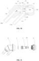
FIG. 12 is a schematic diagram of a nozzle according to another embodiment of the application. - In order to make the purpose, technical solutions and advantages of the application clearer, the application will be further described in detail below with reference to the drawings and embodiments. It should be understood that specific embodiments described here are only intended to explain the application, and are not intended to limit the application.
- At present, taking washing machines as an example, a household washing machine washes laundries with water, and a shrinkage phenomenon easily occurs to fiber structures of the laundries during washing with water. A commercial dry cleaning machine dry-cleans laundries with tetrachlorethylene or a petroleum solvent as a washing medium, which may clean the laundries better and does not easily damage fiber structures of the laundries. However, after washing is completed, the washing medium needs to be distilled and recovered, which is a complicated operation and is not suitable for a household laundry treatment apparatus. At present, the household laundry treatment apparatus is still not capable of dry-cleaning laundries. Dry cleaning refers to a care manner in which a washing medium contains little water.
- An embodiment of the application provides a laundry treatment apparatus, the laundry treatment apparatus may be used as a household laundry dry cleaning device. As shown in
FIG. 1 , an embodiment of the application provides a laundry treatment apparatus, the laundry treatment apparatus includes adelivery port 300, asupporter 200 and a dry cleaningsolvent delivery device 100a. Thedelivery port 300 is configured to deliver a dry cleaning solvent into the laundry treatment apparatus, that is, the user may put the dry cleaning solvent in the laundry treatment apparatus through thedelivery port 300. Thesupporter 200 is a support structure close to a front end of the entire laundry treatment apparatus, and with reference toFIG. 2 , thesupporter 200 may be configured to support abarrel 700 of the laundry treatment apparatus. Anaccommodation chamber 701 is provided in thebarrel 700, and theaccommodation chamber 701 may be configured to accommodate laundries to be dry-cleaned. - With reference to
FIG. 1 andFIG. 2 , thedelivery port 300 is arranged on thesupporter 200, to facilitate the user to put the dry cleaning solvent in thedelivery port 300. The dry cleaningsolvent delivery device 100a is communicated with thedelivery port 300, and the dry cleaningsolvent delivery device 100a is configured to atomize the dry cleaning solvent and spray the atomized dry cleaning solvent into theaccommodation chamber 701. - It should be noted that "atomize" indicates that flow of the dry cleaning solvent put in the
delivery port 300 is guided into the dry cleaningsolvent delivery device 100a, a nozzle injects a high-speed gas to impact the dry cleaning solvent, so that the dry cleaning solvent is dispersed into tiny droplets and forms a mist to be sprayed out of the nozzle, and the mist-like dry cleaning solvent is sprayed on laundries in theaccommodation chamber 701, which is beneficial to increasing a contact area between the dry cleaning solvent and the laundries. Contact between the dry cleaning solvent and the laundries may achieve dissolution of stains on the laundries, to improve uniformity of the dry cleaning solvent sprayed on the laundries. - In the embodiment of the application, the dry cleaning
solvent delivery device 100a may be permanently fixed to thesupporter 200 by welding and bonding, and the dry cleaningsolvent delivery device 100a may also be detachably connected to thesupporter 200 through snap-in members or screws, etc. - In the embodiment of the application, the dry cleaning solvent delivery device is arranged at a front side of the laundry treatment apparatus, and the delivery port is usually arranged at the front side of the laundry treatment apparatus to facilitate the user to put the dry cleaning solvent in the laundry treatment apparatus. Then, when the dry cleaning solvent delivery device is arranged at the front side of the laundry treatment apparatus, it is close to the delivery port, to facilitate that a pipeline communicating the dry cleaning solvent delivery device with a delivery port is set to be short, and the pipeline does not cross from the front side to rear side of the laundry treatment apparatus, therefore it is beneficial to improving smoothness of circulation of the dry cleaning solvent in the pipeline. In the embodiment of the application, the dry cleaning solvent delivery device is arranged on the supporter, and the supporter is configured to support other components in the laundry treatment apparatus, therefore the supporter is reused as a carrier of the dry cleaning solvent delivery device, and it is unnecessary to separately provide an installation seat or other installation structures for the dry cleaning solvent delivery device, so that componentized production of the dry cleaning solvent delivery device and the supporter may be achieved, which is beneficial to reducing assembly difficulty of the dry cleaning solvent delivery device and improving structural compactness of the laundry treatment apparatus, thereby improving feasibility and reliability of mass production of a product formed of the supporter and the dry cleaning solvent delivery device, and facilitating after-sales maintenance of the product.
- In some embodiments, with reference to
FIG. 1 andFIG. 2 , thesupporter 200 is provided with a laundry access opening 200a. The laundry access opening 200a is communicated with theaccommodation chamber 701. The laundry treatment apparatus includes a front sealing plate and a door, the front sealing plate is arranged at a front side of thesupporter 200, and a front surface of the front sealing plate is used as an appearance surface of the laundry treatment apparatus. The front sealing plate is provided with a doorway, the doorway is aligned with the laundry access opening 200a, and the door is configured to open and close the doorway. - The laundry treatment apparatus further includes a door sealing ring, the door sealing ring is connected between the doorway of the front sealing plate and the laundry access opening 200a of the supporter, and is configured to seal a gap between the doorway of the front sealing plate and the laundry access opening 200a of the supporter. When the door is closed, the
accommodation chamber 701 forms a relatively closed space. - In some embodiments, the dry cleaning
solvent delivery device 100a includes anozzle 100. As shown inFIG. 1 , the nozzle includes a body and a branch pipe, the body is configured to conduct a first medium, the branch pipe is configured to conduct a second medium, and the first medium draws the second medium. It may be understood that respective fluid media may circulate in both the body and the branch pipe, and the second medium is drawn through the first medium circulating in the body, so that a mixed medium may be formed to be sprayed out. - It may be understood that the
nozzle 100 may be divided into components in multiple ways. For example, as described above, thenozzle 100 may be divided into the body and the branch pipe according to different fluid media passing there-through. The body may allow the first medium to enter the body from an inlet at an end, and spray out a mixed medium of the first medium and the second medium from an outlet at another end. The branch pipe may allow the second medium to enter the branch pipe from an inlet at an end, and output the second medium from an outlet at another end to the body, so that the second medium is mixed with the first medium. The nozzle may also be divided into a sleeve assembly located at an outer side and a core located in the center and surrounded by the sleeve assembly, according to their position relationships. The sleeve assembly and the core may be formed on the body and/or the branch pipe correspondingly. For example, the sleeve assembly includes a part of the body and the branch pipe, and the core includes another part of the body. Hereinafter, for the sake of simplicity and convenience, descriptions may be made by dividing the nozzle into the sleeve assembly and the core. - In some embodiments, as shown in
FIG. 1 , the dry cleaningsolvent delivery device 100a includes apump 400 and anozzle 100. Thepump 400 is configured to increase a flow speed of a gas. Afirst channel 20 is provided in the body. With reference toFIG. 8 , thefirst channel 20 is communicated with both thepump 400 and thedelivery port 300. Thepump 400 is configured to transport the gas to thefirst channel 20, and thedelivery port 300 is configured to transport the dry cleaning solvent to thefirst channel 20. The gas is mixed with the dry cleaning solvent in thefirst channel 20, to form a gas-liquid mixture. Thefirst channel 20 includes afirst outlet 202 for spraying the gas-liquid mixture, and thefirst outlet 202 sprays the gas-liquid mixture into the accommodation chamber of the laundry treatment apparatus. In the embodiment of the application, the pump is provided to increase a speed of the gas injected into thenozzle 100, which is beneficial to increasing a speed of spraying the gas to the dry cleaning solvent, thereby increasing a degree of dispersing the dry cleaning solvent by the gas, and further improving atomization effect of the dry cleaning solvent. After the dry cleaning solvent is atomized, small droplets of the dry cleaning solvent may uniformly contact surfaces of the laundries, thereby increasing the contact area between the dry cleaning solvent and the laundries, and further improving cleanliness of the laundries. - In some embodiments,
FIG. 6 shows a perspective view of thenozzle 100 according to an embodiment of the application,FIG. 7 shows a side view of thenozzle 100 according to an embodiment of the application, andFIG. 8 shows a cross-sectional view of thenozzle 100 according to an embodiment of the application. Thenozzle 100 includes asleeve assembly 1 and acore 2. As shown inFIG. 8 , afirst accommodation cavity 10 is provided in thesleeve assembly 1. Thecore 2 is arranged in thefirst accommodation cavity 10, and thefirst channel 20 for the first medium to circulate there-through is provided in thecore 2, here the first medium may be a gas. As shown inFIG. 8 , asecond channel 12 is formed between anouter side wall 21 of thecore 2 and aninner side wall 11 of thesleeve assembly 1, and thesecond channel 12 is configured for the second medium to circulate there-through, here the second medium may be the dry cleaning solvent such as tetrachlorethylene, petroleum, etc. The first medium circulates along thefirst channel 20, and draws the second medium in thesecond channel 12 into thefirst channel 20. In a process of drawing the second medium into thefirst channel 20, the first medium originally flowing in thefirst channel 20 may disperse the second medium entering thesecond channel 12, so that the second medium is dispersed into tiny droplets, and thus the second medium forms a mist to be sprayed out of thenozzle 100, and the mist-like dry cleaning solvent is sprayed on laundries in a laundry dryer, which is beneficial to increasing a contact area between the dry cleaning solvent and the laundries. Contact between the dry cleaning solvent and the laundries may achieve dissolution of stains on the laundries, to improve uniformity of the dry cleaning solvent sprayed on the laundries, which is beneficial to improving quality of dry cleaning. - In the embodiment of the application, the
second channel 12 includes avariable diameter section 22. Thesecond channel 12 is formed of a gap between thecore 2 and thesleeve assembly 1, and thesecond channel 12 is arranged around circumference of thecore 2. Thevariable diameter section 22 indicates a situation where an area of a cross section of at least a part of thesecond channel 12 in an axial direction changes, such as a situation where the area of the cross section of thesecond channel 12 in the axial direction becomes small or large. Of course, it does not necessarily indicate that the entiresecond channel 12 shows a changing trend, that is, there is a situation where an area of a cross section of a part of thesecond channel 12 may remain unchanged. It should be noted that the axial direction indicates a length direction of thesecond channel 12 or a length direction of thefirst channel 20. In the embodiment of the application, the length direction of thefirst channel 20 is substantially the same as the length direction of thesecond channel 12. The length direction of thefirst channel 20 indicates a flow direction of the first medium in thefirst channel 20, and the length direction of thesecond channel 12 also indicates a flow direction of the second medium in thesecond channel 12. The cross section of thesecond channel 12 is a cross section of thesecond channel 12 perpendicular to the axial direction (a left-right direction shown inFIG. 8 ). As shown inFIG. 8 , in case that thesecond channel 12 is provided in an axially symmetrical structure, a situation where the cross section of thesecond channel 12 changes may be indicated by a length of thesecond channel 12 in an up-down direction. As may be seen fromFIG. 8 , in the embodiment of the application, thevariable diameter section 22 in thesecond channel 12 changes in the axial direction (the left-right direction shown inFIG. 8 ), and the length of thesecond channel 12 in the up-down direction changes, instead of having a fixed value respectively. - The
second channel 12 is configured to conduct the second medium, and the second medium is a fluid medium. In a process of the second medium flowing along thesecond channel 12, the area of the cross section of thesecond channel 12 changes. For example, as shown inFIG. 8 , an area of a cross section of a part of thesecond channel 12 close to a left side is large, and then due to existence of an outward-protruded oblique surface of the core 2 (that is, a position where thevariable diameter section 22 is located), an area of a cross section of a part of thesecond channel 12 at a right side is small. That is, in a process of flowing from a left side of thevariable diameter section 22 to a right side of thevariable diameter section 22, a pipe diameter of the second channel 12 (an inner diameter of ahousing 11" - an outer diameter of the core) becomes small, then a proportion of the fluid flowing against or close to a wall surface of thesecond channel 12 increases. The fluid has viscosity, and may be subject to resistance from a pipe wall when it flows against the pipe or close to interior of the pipe. Then, since the proportion of the fluid flowing against or close to the wall surface of thesecond channel 12 increases, resistance suffered by the fluid in thesecond channel 12 increases. In case that pressure of the fluid itself does not change (since gas pressure of a gas pump does not change, negative pressure generated in the nozzle has a fixed value, that is, pressure for attracting the second medium into the second channel has a fixed value), a flow rate thereof may decrease. In the embodiment of the application, a flow rate/flow speed of the second medium may be adjusted by setting the variable diameter section of the second channel, so that the flow rate of the second medium may be adjusted to be small, and thus the first medium may fully impact the second medium. In case that the first medium is a gas and the second medium is a liquid, the liquid has a small flow rate and may be impacted by the gas, to be fully broken down into droplets, thereby improving atomization efficiency. - An embodiment of the application provides a nozzle, the nozzle includes a sleeve assembly and a core. A first accommodation cavity is provided in the sleeve assembly. The core is arranged in the first accommodation cavity, and a first channel for the first medium to circulate there-through is provided in the core. An outer side wall of the core is configured so that a second channel for the second medium to circulate there-through is formed between the outer side wall of the core and an inner side wall of the sleeve assembly. The first medium circulates along the first channel and draws the second medium into the first channel, the second channel includes a variable diameter section. In the embodiment of the application, the variable diameter section is provided in the second channel, which is beneficial to controlling the flow speed, intensity of pressure and flow rate of the second medium flowing in the second channel by changing parameters of the variable diameter section. Structural parameters of the variable diameter section are mainly controlled by changing an external size of the core or a size of the first accommodation cavity. Compared to changing a size of connection between the first channel and the second channel, in the embodiment of the application, the structural parameters of the variable diameter section are controlled in a simple and reliable manner, which is beneficial to reducing processing difficulty and reducing manufacturing cost, and reducing control difficulty of the flow rate of the second medium entering the first channel. Therefore, it is beneficial to improving atomization efficiency of the second medium, further improving uniformity of the dry cleaning solvent sprayed on the laundries, and improving cleanliness of dry cleaning.
- In some embodiments, as shown in
FIG. 8 , thecore 2 is provided with a first liquidinlet flow channel 23 communicating thefirst channel 20 with thesecond channel 12. In some embodiments, thefirst channel 20 is arranged along an axial direction of the core 2 (a left-right direction shown inFIG. 8 ), the first liquidinlet flow channel 23 is arranged along a radial direction of thecore 2, and the radial direction indicates a direction perpendicular to the axial direction, that is, an up-down direction shown inFIG. 8 . In thesecond channel 12, after the second medium enters thesecond channel 12, the second medium flows from the first liquidinlet flow channel 23 to thefirst channel 20. That is, a position where the first liquidinlet flow channel 23 is connected to thesecond channel 12 may be considered as an end point of thesecond channel 12. In the embodiment of the application, an area of a cross section of thesecond channel 12 toward a direction close to the first liquidinlet flow channel 23 becomes small, here a changing trend of the area of the cross section of thesecond channel 12 is that the area of the cross section changes in a trend of decreasing in a direction from an end in the axial direction to the first liquidinlet flow channel 23. Manners of changing thesecond channel 12 include, but are not limited to changing in a gradually decreasing trend; or, the area of the cross section of thesecond channel 12 has a fixed value first, and then decreases; or, the area of the cross section of thesecond channel 12 has a fixed value first, then decreases, and then has a fixed value; or, the area of the cross section of thesecond channel 12 changes toward a decreasing trend by changing in multiple gradients. In the embodiment of the application, the first liquid inlet flow channel is provided to communicate the first channel with the second channel, the area of the cross section of the second channel toward the direction close to the first liquid inlet flow channel becomes small, and in a process of the second medium flowing in the second channel toward the direction close to the first liquid inlet flow channel, the area of the cross section of the second channel decreases, and correspondingly, the flow rate of the second medium entering the first liquid inlet flow channel from the second channel becomes small, so that the flow rate of the second medium entering the first channel from the first liquid inlet flow channel decreases, thereby controlling an amount of the second medium impacted by the first medium, which is beneficial to improving atomization effect of the second medium. Specifically, it is beneficial to improving a probability that the second medium is dispersed into tiny droplets, thereby increasing a contact area between the second medium and the laundries, and further improving cleanliness of dry cleaning. Furthermore, in the embodiment of the application, the first channel is arranged along the axial direction of the core, the first liquid inlet flow channel is arranged along the radial direction of the core, and the second channel is also arranged along the axial direction, so that a difference of intensity of pressure between the first liquid inlet flow channel at two positions of connecting the first channel and the second channel respectively are larger, and a larger negative pressure may be generated in the first liquid inlet flow channel, to draw the second medium from the second channel into the first channel, thereby improving atomization efficiency of the dry cleaning solvent. - In some embodiments, as shown in
FIG. 8 , an area of a cross section of thecore 2 toward the direction close to the first liquidinlet flow channel 23 increases. The area of the cross section of thecore 2 described in the embodiment of the application indicates a size of a maximum cross section enclosed by an outer profile of thecore 2 in a direction perpendicular to the axis direction. That is, a size of a cross section of thefirst accommodation cavity 10 in thesleeve assembly 1 close to the first liquidinlet flow channel 23 in the axial direction may become small or may remain unchanged, by increasing a size of the outer profile of thecore 2. Of course, in case that an area of the cross section of thefirst accommodation cavity 10 in thesleeve assembly 1 close to the first liquidinlet flow channel 23 becomes large, a changing rate of the first accommodation cavity needs to be less than a changing rate of thecore 2, thereby ensuring that the area of the cross section of the second channel toward the direction close to the first liquidinlet flow channel 23 becomes small. In the embodiment of the application, the area of the cross section of the second channel may be changed by adjusting the size of the outer profile of thecore 2, the core may be separately processed and manufactured relative to the sleeve assembly, and the core is processed in a simple manner, which is beneficial to improving processing efficiency of the entire spray apparatus, and reducing processing difficulty of variation of size of the second channel. - In some embodiments, the
core 2 is made of a metal material, since in case that the nozzle is applied to a laundry dryer device, there is a heating stage during dry cleaning, the nozzle may be affected by variation of temperature. The metal material has strong structural strength and corrosion resistance, which is beneficial to maintaining stability of structures and sizes under dual effects of a high-speed gas flow and the dry cleaning solvent in a long term, and thus is beneficial to extending service life of the nozzle. - In some embodiments, as shown in
FIG. 8 , thecore 2 includes a small-diameter part 24, aconnection part 26 and a large-diameter part 25. An area of a cross section of the small-diameter part 24 has a first fixed value, an area of a cross section of the large-diameter part 25 has a second fixed value, and the second fixed value is greater than the first fixed value. The area of the cross section of the small-diameter part 24 is an area of a cross section with a maximum size enclosed by an outer profile of the small-diameter part 24, the area of the cross section of the large-diameter part 25 is also an area of a cross section with a maximum size enclosed by an outer profile of the large-diameter part 25. In the embodiment of the application, the second fixed value greater than the first fixed value indicates that the area of the cross section of the large-diameter part 25 is greater than the area of the cross section of the small-diameter part. An end of the connection part 26 (a left end shown inFIG. 8 ) is connected to the small-diameter part 24, another end of the connection part 26 (a right end shown inFIG. 8 ) is connected to the large-diameter part 25, and an area of a cross section of at least a portion of theconnection part 26 gradually increases from an end to another end (from left to right). The first liquidinlet flow channel 23 is arranged at an end of the large-diameter part 25 away from the connection part 26 (that is, in the embodiment shown inFIG. 8 , the first liquidinlet flow channel 23 is arranged at a right end of the large-diameter part 25), thefirst channel 20 penetrates the small-diameter part 24, theconnection part 26 and the large-diameter part 25. Thevariable diameter section 22 is located between theconnection part 26 and thesleeve assembly 1, specifically, thevariable diameter section 22 is formed between an outer side wall of theconnection part 26 and the inner side wall of thesleeve assembly 1. - In the embodiment of the application, the core is configured as the small-diameter part, the connection part and the large-diameter part sequentially connected in the axial direction, the area of the cross section of the small-diameter part is less than the area of the cross section of the large-diameter part, and the area of the cross section of the connection part gradually increases from an end connected to the small-diameter part to an end connected to the large-diameter part. In a process of the second medium flowing from an outer side of the small-diameter part to an outer side of the large-diameter part, the area of the cross section of the second channel decreases, and correspondingly, the flow rate of the second medium entering the first liquid inlet flow channel from the second channel becomes small, so that the flow rate of the second medium entering the first channel from the first liquid inlet flow channel decreases, that is, a volume of the second medium per unit time is small, therefore a number of tiny parts dispersed by impact of the first medium is large and a volume of each tiny part is small. In case that the second medium is a liquid and the first medium is a gas, an effect of fully breaking down the liquid into a large number of tiny droplets by the gas is achieved, which is beneficial for full atomization. The core has a simple structure, and is easy to be processed and manufactured, which is beneficial to reducing production difficulty.
- In some embodiments, as shown in
FIG. 9 , thefirst channel 20 includes adiameter reduction section 27 and adiameter expansion section 28.FIG. 9 shows an enlarged view of a part B inFIG. 8 . Thediameter reduction section 27 is provided with opposite ends in the axial direction, which are afirst end 271 and asecond end 272 respectively. Thefirst end 271 is close to afirst inlet 201 of the first channel compared to thesecond end 272, and thesecond end 272 is close to thefirst outlet 202 of thefirst channel 20 compared to thefirst end 271. As shown inFIG. 9 , an area of a cross section of thediameter reduction section 27 from thefirst end 271 to thesecond end 272 gradually decreases. It should be noted that "gradually decreases" indicates that variation of the area of the cross section of thediameter reduction section 27 has a changing trend of gradually decreasing in a certain slope, the slope may be a fixed value or a continuously changing value, as long as the area of the cross section of thediameter reduction section 27 does not change in a trend of changing suddenly. In the embodiment of the application, the area of the cross section of thediameter reduction section 27 from the first end to the second end gradually decreases. In a flow channel where continuous flow occurs, according to flow continuity of a fluid, a flow rate passing through each cross section in the same flow channel is a constant value, that is, VA = a constant value, here V is a flow speed, and A is an area of each cross section of the flow channel. Therefore, with respect to the first medium passing through thediameter reduction section 27, since an area of a corresponding cross section of the flow channel along a flow direction decreases, a flow speed flowing through each cross section along the flow direction increases; and according to Bernoulli's equation, a sum of pressure potential energy, kinetic energy and gravitational potential energy at any two points on a flow line remains unchanged, then along the flow direction, since the flow speed increases, the kinetic energy increases correspondingly, while the gravitational potential energy substantially remains unchanged, then the pressure potential energy decreases, that is, intensity of pressure of the first medium may decrease along the flow direction. When a speed of the first medium further increases, it is beneficial to increasing a speed of the first medium impacting the second medium, thereby improving an effect of dispersing the second medium by the first medium. Furthermore, the intensity of pressure of the first medium decreases, which is beneficial to forming a greater negative pressure in the first channel, and thus is more beneficial to drawing the second medium in the second channel into the first channel. - As shown in
FIG. 9 , the first liquidinlet flow channel 23 is provided with opposite ends in the radial direction, one of which is asecond inlet 232, and another one of which is asecond outlet 231. Thesecond inlet 232 of the first liquidinlet flow channel 23 is connected to thesecond channel 12, and thesecond outlet 231 of the first liquidinlet flow channel 23 is connected to thefirst channel 20. Thesecond outlet 231 of the first liquidinlet flow channel 23 is arranged on thediameter expansion section 28, that is, the second medium in the first liquidinlet flow channel 23 flows directly into thediameter expansion section 28 of thefirst channel 20 after flowing out from thesecond outlet 231. As shown inFIG. 9 , thediameter expansion section 28 is extended from a position close to thesecond end 272 to thefirst outlet 202 of thefirst channel 20, and an area of a cross section of thediameter expansion section 28 toward a direction close to thefirst outlet 202 gradually increases. Under an action of thediameter reduction section 27, the speed of the first medium in thefirst channel 20 increases, and the intensity of pressure of the first medium decreases. At a moment when the first medium in thediameter reduction section 27 enters thediameter expansion section 28, since an area of a cross section of a flow channel between thediameter reduction section 27 and thediameter expansion section 28 is a minimum cross-sectional area in the first channel, and VA = a constant value according to a continuity equation of a liquid fluid, here V is a flow speed, and A is an area of each cross section of the flow channel, then a flow speed of the first medium at a cross section where thesecond outlet 231 is located is maximum. According to Bernoulli's equation, a pressure potential energy at this position is minimum. Then, in the embodiment of the application, thesecond outlet 231 is connected to the diameter expansion section, which is beneficial to achieving that the first medium impacts the second medium at a greater speed, and is beneficial to forming a greater negative pressure at thesecond outlet 231, to draw the second medium into the first channel, and reduce a risk of the second medium flowing back to the first liquid inlet flow channel, and is beneficial to improving an effect of dispersing the second medium, and further improving atomization effect of the second medium. Furthermore, the area of the cross section of the diameter expansion section gradually increases, which is beneficial to improving a diffusion effect after the second medium is impacted by the first medium. Furthermore, in the embodiment of the application, thesecond outlet 231 is arranged in the diameter expansion section, and a certain inclined angle is present between a direction in which the second medium runs out from the second outlet and a wall surface of the diameter expansion section, compared to a situation where the second outlet is arranged in the diameter reduction section or other positions. The diameter expansion section is beneficial to guiding the gas toward a direction of the diameter expansion section close to thefirst outlet 202, thereby reducing a risk of the gas or liquid flowing back to the first liquid inlet flow channel or the diameter reduction section. - In some embodiments, an inlet for guiding the second medium in the
second channel 12 may be arranged to be offset to thesecond inlet 232 of the first liquidinlet flow channel 23 in a circumferential direction. That is, a projection of the inlet of the second medium in thesecond channel 12 may not coincide with a projection of thesecond inlet 232 in the circumferential direction. After the second medium enters thesecond channel 12, a path of the second medium from the inlet in thesecond channel 12 to thesecond inlet 232 is twisted, so that the liquid rotatably goes forward, and finally enters the first liquidinlet flow channel 23 from thesecond inlet 232. The second medium moved rotatably may generate an impact action with the gas in thesecond channel 12, thereby achieving pre-atomization of the second medium. In the embodiment of the application, the inlet of thesecond channel 12 is arranged to be offset to thesecond inlet 232 of the first liquidinlet flow channel 23 in the circumferential direction, which is beneficial to extending a path of the second medium flowing in the second channel and enhancing impact effect between the second medium and the gas, thereby improving pre-atomization effect. - In some embodiments, as shown in
FIG. 9 , multiple first liquidinlet flow channels 23 may be provided, and multiple first liquidinlet flow channels 23 are arranged at intervals in a circumferential direction of the large-diameter part. In the embodiment of the application, the number of the first liquidinlet flow channels 23 is less than or equal to 8. In the embodiment shown inFIG. 9 , four first liquidinlet flow channels 23 are provided. That is, when the number of the first liquidinlet flow channels 23 increases, on one hand, an effect of disturbing the second medium in the second channel may be improved, to improve an effect of pre-atomizing the second medium in the second channel; on the other hand, the number of the first liquid inlet flow channels is limited to a certain range, which may control intensity of pressure of the second medium exported from each of the first liquid inlet flow channels, so that the negative pressure in the first channel may draw the second medium in each of the first liquid inlet flow channels as much as possible, thereby improving flow efficiency of the second medium. - In some embodiments, the
first channel 20 further includes athroat section 281, thethroat section 281 connects thesecond end 272 of thediameter reduction section 27 to thediameter expansion section 28, and an area of a cross section of thethroat section 281 is equal to the area of the cross section of thediameter reduction section 27 at thesecond end 272. In the embodiment of the application, thethroat section 281 is provided, which is beneficial to stabilizing a gas flow introduced from thediameter reduction section 27. That is, the flow speed of the first medium increases in thediameter reduction section 27, and the speed of the first medium entering thethroat section 281 is a maximum value. Thesecond outlet 231 is arranged at an end of thediameter expansion section 28 close to thethroat section 281. The speed of the first medium exported from thethroat section 281 is a maximum speed, and the intensity of pressure of the first medium is minimum, so that a large negative pressure may be formed at a position of thesecond channel 12 close to thesecond outlet 231, to draw the second medium into thediameter expansion section 28, reduce a risk of the second medium flowing back to the first liquidinlet flow channel 23, and improve atomization effect of the second medium. - In some embodiments, with reference to
FIG. 8 andFIG. 9 , thefirst channel 20 further includes anequal diameter section 29. An end of the equal diameter section 29 (a left end shown inFIG. 8 ) is connected to thefirst inlet 201 of thefirst channel 20, and as shown inFIG. 9 , another end of the equal diameter section 29 (a right end shown inFIG. 8 ) is connected to thediameter reduction section 27. An area of a cross section of theequal diameter section 29 is equal to an area of a cross section of thefirst end 271 of thediameter reduction section 27. After the first medium is guided from thefirst inlet 201 to theequal diameter section 29, the first medium enters thediameter reduction section 27 from the equal diameter section. In some embodiments, a second diameter reduction section may also be arranged at an end of theequal diameter section 29 close to thefirst inlet 201, an end of the second diameter reduction section forms thefirst inlet 201, and another end of the second diameter reduction section is connected to an end of theequal diameter section 29 away from thediameter reduction section 27. When the second diameter reduction section is arranged at an end of theequal diameter section 29, it is beneficial to further increasing the speed of the first medium entering thefirst channel 20 from thefirst inlet 201, and reducing the intensity of pressure of the first medium, thereby increasing the negative pressure of drawing the second medium, and improving an effect of dispersing the second medium into a mist. - In some embodiments, with reference to
FIG. 8 ,FIG. 11 and FIG. 10 , thesleeve assembly 1 includes asleeve body 13 and acover 14. A part of thefirst accommodation cavity 10 is provided in thesleeve body 13, thecover 14 is detachably connected to thesleeve body 13, and another part of thefirst accommodation cavity 10 is formed in thecover 14. An end of thecore 2 in the axial direction (a left end shown inFIG. 8 ) abuts against thesleeve body 13, and another end of thecore 2 in the axial direction (a right end shown inFIG. 8 ) abuts against thecover 14. Manners of connecting thesleeve body 13 to thecover 14 are not limited in the embodiment of the application. For example, in embodiments shown inFIG. 11 and FIG. 10 , thesleeve body 13 may be connected to thecover 14 through threads there-between. In other embodiments, thesleeve body 13 may also be detachably connected to thecover 14 through screws or snap-in structures there-between. In the embodiment of the application, the sleeve body is detachably connected to the cover, to facilitate assembly of the core into the first accommodation cavity, and the sleeve body and the cover may be processed and manufactured separately, which is beneficial to improving processing and assembly efficiency. - In some embodiments, as shown in
FIG. 8 ,FIG. 11 and FIG. 10 , the nozzle further includes asealing ring 3, the sealingring 3 is arranged between an end of thecore 2 in the axial direction (a left end shown inFIG. 8 ) and thesleeve body 13, that is, the sealingring 3 is configured to close a gap between thecore 2 and thesleeve body 13, to reduce a risk of the first medium guided from agas inlet channel 132 into thefirst channel 20 flowing from the gap to thesecond channel 12, which is beneficial to forming a large negative pressure in thefirst channel 20 to draw the second medium in the second channel into the first channel, and thus is beneficial to atomizing and spraying the dry cleaning solvent. - In some embodiments, as shown in
FIG. 8 , thesleeve body 13 further includes aliquid inlet channel 131 and agas inlet channel 132. Theliquid inlet channel 131 is communicated with thesecond channel 12, and theliquid inlet channel 131 is configured to guide flow of the second medium to thesecond channel 12; thegas inlet channel 132 is communicated with thefirst inlet 201 of thefirst channel 20, and thegas inlet channel 132 is configured to guide flow of the first medium to thefirst channel 20. As shown inFIG. 8 , theliquid inlet channel 131 is connected to an end of thesecond channel 12 away from the firstliquid inlet channel 23. That is, flow of the second medium guided in theliquid inlet channel 131 enters the second channel from an end of the second channel, and an end of theliquid inlet channel 131 connected to the second channel is away from the first liquidinlet flow channel 23 in the axial direction. In the embodiment of the application, there is a certain gap at a position where thecover 14 is connected to thesleeve body 13, the gas outside thenozzle 100 may enter thesecond channel 12 from the gap, the second medium in theliquid inlet channel 131 may run into thesecond channel 12 according to a certain frequency gap, and the second medium may impact the gas in thesecond channel 12, so that the second medium is dispersed into small droplets in thesecond channel 12, thereby achieving its pre-atomization in the second channel. In the embodiment of the application, a position where theliquid inlet channel 131 is connected to the second channel is away from the first liquidinlet flow channel 23, which may increase a gas storage capacity in the second channel and increase time of pre-atomizing the second medium in the second channel. - In some embodiments, as shown in
FIG. 1 , the laundry treatment apparatus further includes agas inlet pipe 501, agas outlet pipe 502 and aliquid inlet pipe 503. Thegas inlet pipe 501 is connected to agas inlet 401 of thepump 400, and thegas inlet pipe 501 is configured to guide the gas outside the laundry treatment apparatus into thepump 400 through thegas inlet 401 of thepump 400, to increase intensity of pressure of the gas and increase a speed of exporting the gas through thepump 400. With reference toFIG. 4 andFIG. 5 , thegas outlet pipe 502 connects agas outlet 402 of thepump 400 to an end of thegas inlet channel 132 away from thefirst channel 20, that is, thegas outlet pipe 502 is configured to guide a high-pressure gas into thegas inlet channel 132, and finally the high-pressure gas is guided into thefirst channel 20 through thegas inlet channel 132. As shown inFIG. 1 , theliquid inlet pipe 503 connects thedelivery port 300 to an end of theliquid inlet channel 131 away from thesecond channel 12, theliquid inlet pipe 503 is configured to guide flow of the dry cleaning solvent put in thedelivery port 300 to theliquid inlet channel 131, the dry cleaning solvent is introduced into thesecond channel 12 through theliquid inlet channel 131, and then the dry cleaning solvent in thesecond channel 12 is drawn into thefirst channel 20 through the first liquidinlet flow channel 23 on thecore 2. The high-pressure gas impacts the dry cleaning solvent, so that the dry cleaning solvent is dispersed into small-size droplets, and the droplets spread out to form a mist to be sprayed into the accommodation chamber. - With reference to
FIG. 5 , in the embodiment of the application, thegas inlet pipe 501, thegas outlet pipe 502 and theliquid inlet pipe 503 are located at a front side of thesupporter 200, and thefirst outlet 202 is located at a rear side of thesupporter 200. Specifically, thegas inlet pipe 501, thegas outlet pipe 502 and theliquid inlet pipe 503 are connected to thesleeve body 13 of thenozzle 100, another side of thesleeve body 13 is located at the rear side of thesupporter 200, and a rear side of thesleeve body 13 is detachably connected to thecover 14. In the embodiment of the application, thegas inlet pipe 501, thegas outlet pipe 502 and theliquid inlet pipe 503 are arranged at the front side of thesupporter 200, and thegas inlet pipe 501, thegas outlet pipe 502 and theliquid inlet pipe 503 are connected to thesleeve body 13 of thenozzle 100 at the front side of thesupporter 200, which may avoid providing, on thesupporter 200, through holes for thegas inlet pipe 501, thegas outlet pipe 502 and theliquid inlet pipe 503 to pass there-through, so that it is beneficial to sealing the accommodation chamber in the laundry treatment apparatus; furthermore, thecover 14 is not connected to thegas inlet pipe 501, thegas outlet pipe 502 and theliquid inlet pipe 503, which is beneficial to improving disassembly flexibility of thecover 14 and thesleeve body 13, therefore they are easy to be replaced and repaired. - In some embodiments, with reference to
FIG. 2 ,FIG. 3 andFIG. 5 , thenozzle 100 is arranged on an upper part of thesupporter 200, and thefirst outlet 202 faces a lower rear part of thesupporter 200. It should be noted that "up", "down", "front" and "rear" described in the embodiment of the application indicate directions of the laundry treatment apparatus in a normal usage state. The front of thesupporter 200 indicates a side of thesupporter 200 close to the user, the rear of thesupporter 200 indicates a side of thesupporter 200 away from the user. Thesupporter 200 is provided with an opening penetrating both front and rear sides thereof, the opening is communicated with theaccommodation chamber 701, and the user may take laundries out of theaccommodation chamber 701 and put laundries in theaccommodation chamber 701 through the opening. In the embodiment of the application, "thenozzle 100 is arranged on the upper part of thesupporter 200" may be understood as: thenozzle 100 is arranged above the opening. Thefirst outlet 202 of thenozzle 100 faces the lower rear part of thesupporter 200, here the lower rear part indicates that the dry cleaning solvent sprayed from thefirst outlet 202 moves downward into theaccommodation chamber 701 at a certain inclined angle. In the embodiment of the application, the nozzle is arranged on the supporter at a certain inclined angle, which is beneficial to increasing a spray distance of the dry cleaning solvent sprayed from the first outlet, thereby increasing an area of spraying the dry cleaning solvent on the laundries in the accommodation chamber, which is beneficial to improving cleanliness of the laundries in the accommodation chamber. - In some embodiments, with reference to
FIG. 1 andFIG. 2 , thepump 400 is arranged below the front side of thesupporter 200, which is beneficial to reducing interference of the pump on the accommodation chamber. The pump may be accommodated by a space formed between a front side panel of the laundry treatment apparatus and the supporter, and componentized production of the pump and the supporter may be achieved, which is beneficial to reducing assembly difficulty of the dry cleaning solvent delivery device and improving structural compactness of the laundry treatment apparatus. - In some embodiments, with reference to
FIG. 1 andFIG. 2 , thepump 400 and thedelivery port 300 are arranged at left and right sides of thesupporter 200 respectively. It should be noted that the left and right sides indicate two sides of the laundry treatment apparatus facing actions of the user in a normal usage state. In the embodiment of the application, thepump 400 and thedelivery port 300 are arranged at two sides of thesupporter 200, which is beneficial to reducing wiring difficulty and improving compactness of the assembly. - In some embodiments, with reference to
FIG. 1 andFIG. 2 , the laundry treatment apparatus further includes aliquid storage box 600 configured to store the dry cleaning solvent. Thedelivery port 300 is arranged close to theliquid storage box 600, which is beneficial to reduce a length of a conduit connecting thedelivery port 300 to theliquid storage box 600, thereby reducing an amount of the dry cleaning solvent remaining in the conduit, further increasing utilization rate of the dry cleaning solvent delivered by thedelivery port 300. - In some embodiments, the
liquid storage box 600 is close to thedelivery port 300, and center of theliquid storage box 600 is lower than thedelivery port 300, which is beneficial to guiding the dry cleaning solvent delivered by thedelivery port 300 into theliquid storage box 600 as much as possible, thereby improving delivery efficiency of the dry cleaning solvent. It should be noted that the center of theliquid storage box 600 indicates a geometric center of theliquid storage box 600. - In some embodiments, the nozzle sprays the gas-liquid mixture intermittently, and there is a certain time interval between a previous time of spraying the dry cleaning solvent on the laundries by the nozzle and a next time of spraying the dry cleaning solvent on the laundries by the nozzle. Compared to spraying the dry cleaning solvent continuously, this time interval may allow fibers of the laundries to fully mix with the dry cleaning solvent, improving an ability of decontaminating the laundries and utilization efficiency of the dry cleaning solvent.
- In some embodiments, the
pump 400 is a pulse gas pump to spray a gas flow intermittently, so that the liquid may be sprayed intermittently, generating an effect of spraying the gas-liquid mixture intermittently. - In some embodiments, as shown in
FIG. 1 , a height difference between thenozzle 100 and theliquid storage box 600 is 10~120 cm. It may be understood that in a normal operation state, thenozzle 100 is at a position close to the upper part of the supporter, and theliquid storage box 600 is at a position close to a lower part of the supporter, that is, there is a certain height difference between thenozzle 100 and theliquid storage box 600. According to the above analysis, thepump 400 delivers the gas to the first channel in thenozzle 100 to generate a negative pressure in the first channel, theliquid storage box 600 is communicated with thedelivery port 300 to be in a normal pressure state, and existence of a pressure difference may allow the liquid in theliquid storage box 600 to be drawn into the first channel through theliquid inlet pipe 503 and the second channel in thenozzle 100. At a moment when the liquid reaches the first channel, gas pressure in the first channel impacts the liquid to atomize the liquid. Furthermore, since a position where the liquid enters the first channel is a position close to a minimum cross section of the first channel (the pressure is minimum at the position), the liquid entering the first channel prevents the gas from flowing in the first channel in a short time, so that the negative pressure is not present in the first channel, and correspondingly, the liquid cannot be drawn. After a short period of time, the liquid in the first channel runs out, and the gas in the first channel resumes continuous flow, thereby generating a negative pressure again to draw the liquid. By repeating in this way, there is an effect of drawing the liquid intermittently and spraying the mist in pulse. It may be understood that in case that the pump delivers the gas stably, the negative pressure that may be generated in the first channel of thenozzle 100 is substantially stable, that is, a difference of intensity of pressure between the first channel and the liquid storage box is a fixed value. A difference of intensity of pressure between the negative pressure and a normal pressure provides power to draw the liquid upward, and only when the difference of intensity of pressure is greater than ρgh (ρ is a density of the liquid, g is a gravity constant, h is a height difference risen by drawing, ρgh reflects gravity of the drawn liquid), the liquid may be drawn to a position higher than an initial position (position of the liquid storage box) by h. Since the difference of intensity of pressure between the liquid storage box and the first channel in the nozzle is a fixed value, the liquid cannot be drawn to this height in case that h is large, therefore h cannot be too large. If h is too small, the difference of intensity of pressure may work against gravity of the liquid, that is, there is still a large power after drawing the liquid to the height h, therefore no liquid may stay in the first channel, that is, intermittent spray may not be formed, instead, continuous spray may be formed. - It may be understood that there are many ways to achieve intermittent spray, which are not limited to the above ways of using a pulse gas pump and/or adjusting a moderate height difference between the liquid storage box and the spray, to achieve intermittent spray.
- With reference to
FIG. 8 , a first end of the body is provided with a spray port, that is, the abovefirst outlet 202, and abranch pipe 1" is connected to a side of the body, that is, connected to any portion at a circumferential side of afirst spray part 1A. - With reference to
FIG. 5 , thesupporter 200 is provided with a throughhole 200b. A part of the body passes through the throughhole 200b and is extended into a side of thesupporter 200 toward theaccommodation chamber 701, thebranch pipe 1" is located at an outer side of thesupporter 200. The outer side of thesupporter 200 refers to a side of the supporter away from the laundry access opening 200a or theaccommodation chamber 701. Specifically, when the door is closed, the outer side of thesupporter 200 is located outside a closed space formed by theaccommodation chamber 701 and the laundry access opening 200a. Since thebranch pipe 1" is arranged at the outer side of thesupporter 200, only one throughhole 200b for the body to pass there-through needs to be provided on thesupporter 200, and it is unnecessary to provide a groove or hole on thesupporter 200 to accommodate thebranch pipe 1", which facilitates installation. - Exemplarily, with reference to
FIG. 1 andFIG. 2 , the throughhole 200b and thenozzle 100 are located above the laundry access opening 200a. In this way, after the mist is sprayed from the spray port, the mist spreads farther along a front-rear direction in theaccommodation chamber 701 and covers a wider range, which may allow the medium in the mist to contact the laundries better. - Exemplarily, with reference to
FIG. 6 andFIG. 12 , the body includes afirst spray part 1A and asecond spray part 1B. A first end of thefirst spray part 1A is provided with a spray port, and thesecond spray part 1B is connected to a second end of thefirst spray part 1A. Thebranch pipe 1" may be connected to thefirst spray part 1A or thesecond spray part 1B. - With reference to
FIG. 5 , when thenozzle 100 is extended into thesupporter 200, thefirst spray part 1A is obliquely arranged relative to a horizontal plane, and the first end of thefirst spray part 1A is inclined downward, here the first end of thefirst spray part 1A refers to an end away from thesecond spray part 1B, that is, an end where the spray port is located. Thesecond spray part 1B is arranged along a front-rear direction in the horizontal plane. That is, thefirst spray part 1A and thesecond spray part 1B form a meander-like structure, and thefirst spray part 1A is obliquely extended rearward and downward from a rear end of thesecond spray part 1B. Since the laundries are easy to be accumulated in a lower part of the accommodation chamber under an action of gravity, the spray port is inclined downward, and the mist such as the dry cleaning agent from the spray port may fall in a parabola under an action of its initial speed and gravity, so that the liquid such as the dry cleaning agent is more dispersed, to cover the laundries in the accommodation chamber in a wider range, and facilitate the liquid such as the dry cleaning agent to be attached to the laundries directly, thereby improving a cleaning effect. - It may be understood that the mist refers to a form of droplets where the liquid is dispersed in a granular shape. Exemplarily, diameter of the mist-like droplet may be not greater than 50 µm. This is just an exemplary diameter of the mist-like droplet.
- Exemplarily, with reference to
FIG. 10 , an included angle β formed between an extension direction of thefirst spray part 1A and an extension direction of thesecond spray part 1B is 110°~150°, such as 110°, 113°, 120°, 125°, 130°, 137°, 140°, 144°, 150°. This angle range allows the mist sprayed from thecore 2 to be sprayed on the laundries in theaccommodation chamber 701 along an oblique downward direction better. - Exemplarily, the
branch pipe 1" is arranged parallel to thesecond spray part 1B, that is, thebranch pipe 1" is arranged in the front-rear direction. In this way, it facilitates external pipes to be connected to thesecond spray part 1B and thebranch pipe 1" centrally from the front side of thesupporter 200. - Exemplarily, with reference to
FIG. 1 andFIG. 2 , thesupporter 200 includes aring part 2001 and asurrounding part 2002. Thering part 2001 defines the laundry access opening 200a. Thesurrounding part 2002 is extended from an axial rear end of thering part 2001 to a front edge of thebarrel 700, and thesurrounding part 2002 is substantially in a shape of a trumpet. A radial outer end of thesurrounding part 2002 is configured to cooperate with thebarrel 700 rotatably. With reference toFIG. 5 , the throughhole 200b penetrates thesurrounding part 2002. That is, thenozzle 100 passes through thesurrounding part 2002 from front to rear. - With reference to
FIG. 5 ,FIG. 6 andFIG. 12 , thenozzle 100 includes alimit plate 4, thelimit plate 4 is configured to abut against a portion around the throughhole 200b in a front surface of thesupporter 200. After thefirst spray part 1A is inserted into the throughhole 200b, thelimit plate 4 abuts against the front surface of thesupporter 200, to prevent thenozzle 100 from inserting into the throughhole 200b continuously. In this way, thenozzle 100 may be quickly inserted into place. - In some embodiments, connection holes are provided in the
limit plate 4. Fasteners such as screws or the like pass through the connection holes and are screwed into thesupporter 200, so that thenozzle 100 may be installed on thesupporter 200. - Exemplarily, in some embodiments, with reference to
FIG. 5 andFIG. 12 , a plate surface of thelimit plate 4 is perpendicular to the extension direction of thesecond spray part 1B. With reference toFIG. 5 , a front surface of thesurrounding part 2002 is formed with a boss 2002', and the throughhole 200b penetrates the boss 2002'. The boss 2002' is provided with avertical positioning surface 2002a. Thelimit plate 4 abuts against thevertical positioning surface 2002a. In this way, it may be ensured that thesecond spray part 1B and thebranch pipe 1" are substantially horizontally arranged in the front-rear direction. - In some other embodiments, the
supporter 200 is provided with an inclined installation surface in a portion around the throughhole 200b. With reference toFIG. 6 , the plate surface of thelimit plate 4 is perpendicular to the extension direction of thefirst spray part 1A, and thelimit plate 4 abuts against the inclined installation surface. In this way, it may be ensured that thesecond spray part 1B and thebranch pipe 1" are substantially horizontally arranged in the front-rear direction. - Exemplarily, with reference to
FIG. 2 , the laundry treatment apparatus includes aliquid inlet pipe 503, agas pump 400 and agas outlet pipe 502. Theliquid inlet pipe 503 is communicated with aninlet 131a of theliquid inlet channel 131, and thegas outlet pipe 502 communicates a gas outlet of thegas pump 400 with aninlet 132a of thegas inlet channel 132. Thenozzle 100 is configured to spray an atomized dry cleaning agent to thebarrel 700. - It should be noted that during dry cleaning, the laundry treatment apparatus according to the embodiment of the application adopts a non-soak light dry cleaning mode. The laundries are not immersed in the liquid (water or the dry cleaning agent), and no liquid is accumulated in the
accommodation chamber 701. - Exemplarily, with reference to
FIG. 2 , thegas outlet pipe 502 is arranged around the laundry access opening 200a from a lower left side of the laundry access opening 200a to an upper side of the laundry access opening 200a, and theliquid inlet pipe 503 is arranged around the laundry access opening 200a from a lower right side of the laundry access opening 200a to the upper side of the laundry access opening 200a. That is, thegas outlet pipe 502 is substantially arranged at a left side of the laundry access opening 200a, and theliquid inlet pipe 503 is substantially arranged at a right side of the laundry access opening 200a. In this way, space at left and right sides may be fully used to arrange thegas outlet pipe 502 and theliquid inlet pipe 503, so that an overall structure of thesupporter 200 is more compact. - Exemplarily, with reference to
FIG. 2 , the above delivery port is provided in a bottom wall of the laundry access opening. The user may pour the dry cleaning agent into thedelivery port 300 from the laundry access opening, or insert a dry cleaning agent bottle into thedelivery port 300, and the dry cleaning agent bottle is not pulled out in a process of the laundry treatment apparatus performing a dry cleaning program. - Exemplarily, with reference to
FIG. 3 , the laundry treatment apparatus includes abase 500. A bottom end of thesupporter 200 is connected to thebase 500 and is supported on thebase 500. - Exemplarily, with reference to
FIG. 1 andFIG. 2 , anair duct 200d is provided in a lower end of thesupporter 200, and the laundry treatment apparatus includes a filter apparatus arranged in theair duct 200d. Anair hole 200c is provided in the bottom wall of the laundry access opening 200a of thesupporter 200, and theair duct 200d is communicated with theair hole 200c. A gas flow in theaccommodation chamber 701 enters theair duct 200d from theair hole 200c, flows through the filter apparatus, and is filtered. - A circulation air duct is provided in the
base 500, and communicates theair duct 200d with a gas inlet of theaccommodation chamber 701. A drying airflow sequentially circulates in theaccommodation chamber 701, theair duct 200d and the circulation air duct, to achieve drying of the laundries. - Exemplarily, with reference to
FIG. 6 andFIG. 12 , thefirst spray part 1A includes ahousing 11" (seeFIG. 10 ), thecore 2 and acover 12. Thehousing 11" may be at least a part of the barrel in the above embodiment. - A space in the
branch pipe 1" forms theliquid inlet channel 131. InFIG. 10 , 131a is an inlet of theliquid inlet channel liquid inlet channel 131. - With reference to
FIG. 10 , thehousing 11" is provided with afirst groove 11a, and thefirst groove 11a is provided with an opening. An outlet of a flow channel in thebranch pipe 1" is arranged at a side wall of thefirst groove 11a. Thecore 2 is detachably arranged in thefirst groove 11a, and a spray port is arranged on thecore 2. Thecover 12 detachably covers the opening, thecover 12 is provided with anavoidance port 12c, and theavoidance port 12c is configured to avoid the spray port. - In some embodiments, an example is that the
housing 11" and thecore 2 are two separate components. During assembly, thecore 2 is arranged in thefirst groove 11a from the opening, and then thefirst groove 11a is covered by thecover 12. When thecore 2 is blocked, aged or subject to other phenomena, thecover 12 may be opened, and thecore 2 is taken out to be replaced by anew core 2. - In some embodiments, an example is that the
cover 12 and thecore 2 are an inseparable whole member, during assembly, when it is covered by thecover 12, thecore 2 is arranged in thefirst groove 11a from the opening, while thecover 12 is fixed. When thecore 2 is blocked, aged or subject to other phenomena, it is replaced by a new whole member formed of thecore 2 and thecover 12. - Exemplarily, with reference to
FIG. 10 , thecover 12 is provided with asecond groove 12a, and thesecond groove 12a is docked with thefirst groove 11a along a length direction of thecore 2. - With reference to
FIG. 8 , a part of thecore 2 is inserted into thefirst groove 11a, and another part of thecore 2 is inserted into thesecond groove 12a. That is, thefirst groove 11a and thesecond groove 12a define an installation chamber 1a for installing thecore 2 together. In this way, thecover 12 and thehousing 11" accommodate thecore 2 together, by giving consideration to sizes of both thehousing 11" and thecover 12 in the length direction of thecore 2. - Exemplarily, with reference to
FIG. 10 , afirst positioning surface 11b surrounding theoutlet 132a of thegas inlet channel 132 is provided in bottom of thefirst groove 11a, and anavoidance port 12c for avoiding the spray port of thecore 2 and asecond positioning surface 12b surrounding theavoidance port 12c are provided in bottom of thesecond groove 12a. Thecover 12 is threadedly connected to thehousing 11", and opposite ends of thecore 2 are clamped between thefirst positioning surface 11b and thesecond positioning surface 12b. - In a process of screwing the
cover 12 on thehousing 11", a distance between thefirst positioning surface 11b and thesecond positioning surface 12b gradually decreases, until the opposite ends of thecore 2 are clamped on thefirst positioning surface 11b and thesecond positioning surface 12b. Since the threaded connection may achieve continuous adjustment of the distance between thefirst positioning surface 11b and thesecond positioning surface 12b, the threaded connection between thecover 12 and thehousing 11" may clamp thecore 2 there-between, no matter whether there is an error in length of thecore 2, thereby eliminating respective gaps between the opposite ends of thecore 2 and thefirst positioning surface 11b and thesecond positioning surface 12b. - Exemplarily, with reference to
FIG. 10 , an end of thecover 12 close to thehousing 11" forms a threaded section. The threaded section is extended from the opening into thefirst groove 11a, and cooperates with an internal thread on an inner wall of thefirst groove 11a. - Exemplarily, with reference to
FIG. 10 , anannular positioning platform 111 is provided in the bottom of thefirst groove 11a, thefirst positioning surface 11b surrounds theannular positioning platform 111, and a circumferential surface of theannular positioning platform 111 and a circumferential inner wall of thefirst groove 11a define anannular slot 11c together. With reference toFIG. 10 , an end of thecore 2 is inserted into theannular slot 11c. - It should be noted that the bottom of the
first groove 11a refers to a side of thefirst groove 11a away from the opening. - In the embodiment, the
annular positioning platform 111 plays a role of positioning thecore 2 better, to prevent thecore 2 from moving in thefirst groove 11a along any side perpendicular to the length direction of thecore 2, and also to allow thecore 2 to be accurately inserted into a correct position during assembly, to facilitate an inlet of a Venturi flow channel 13a to be aligned with an outlet 2a" of thegas inlet channel 132. - Exemplarily, with reference to
FIG. 8 , anannular groove 131a is provided in a circumferential outer surface of an end of thecore 2 close to the outlet 2a" of thegas inlet channel 132, that is, theannular groove 131a surrounds an outer circumferential surface of thecore 2. With reference toFIG. 8 , thenozzle 100 includes asealing ring 3, the sealingring 3 is arranged in theannular groove 131a and hermetically abuts against the circumferential inner wall of thefirst groove 11a. The sealingring 3 may enhance sealing performance between thecore 2 and the circumferential inner wall of thefirst groove 11a, and reduce a probability that a fluid in thegas inlet channel 132 enters theliquid inlet channel 131 along a gap between thecore 2 and the circumferential inner wall of thefirst groove 11a. - Exemplarily, the gas inlet channel is formed at a position where the
cover 12 threadedly cooperates with thehousing 11". The threaded cooperation between thecover 12 and thehousing 11" may allow a small amount of gas to flow from a thread gap to a position where thefirst groove 11a is docked with thesecond groove 12a. Threaded docking between thehousing 11" and thecover 12 is located at a side wall corresponding to the second channel. In this way, during spray, air from outside is continuously drawn into the second channel 1b from a position where threaded docking is located, so that the liquid coming from theliquid inlet channel 131 may be pre-mixed with the air in the second channel 1b better. - The above descriptions are only preferred embodiments of the application, and are not intended to limit the scope of protection of the application.
Claims (15)
- A laundry treatment apparatus, comprising:a supporter, connected to a laundry treatment drum, and configured to support the laundry treatment drum; anda dry cleaning solvent delivery device, configured to spray dry cleaning solvent into the laundry treatment drum;wherein the dry cleaning solvent delivery device is at least partially arranged on the supporter.
- The laundry treatment apparatus of claim 1, wherein the dry cleaning solvent delivery device comprises:
a nozzle, comprising a body and a branch pipe, wherein the body is configured to conduct a first medium, the branch pipe is configured to conduct a second medium, and the first medium draws the second medium. - The laundry treatment apparatus of claim 2, wherein a first channel is provided in the body, the first medium comprises gas, the second medium comprises the dry cleaning solvent, the gas is mixed with the dry cleaning solvent in the first channel to form a gas-liquid mixture, and the first channel comprises a first outlet for spraying the gas-liquid mixture.
- The laundry treatment apparatus of claim 3, wherein the nozzle comprises:a sleeve assembly, wherein a first accommodation cavity is provided in the sleeve assembly; anda core, arranged in the first accommodation cavity, wherein the sleeve assembly is detachably connected to the core.
- The laundry treatment apparatus of claim 4, wherein a gas inlet channel and a liquid inlet channel are also provided in the sleeve assembly, and the first channel communicated with the gas inlet channel is provided in the core; a second channel communicated with the liquid inlet channel is formed between an outer side wall of the core and an inner side wall of the sleeve assembly, and the core is provided with a first liquid inlet flow channel communicating the first channel with the second channel.
- The laundry treatment apparatus of claim 5, wherein the first channel comprises:a diameter reduction section, having a cross-sectional area that gradually decreases from a first end to a second end, wherein the first end is an end close to the gas inlet channel;a diameter expansion section, extended from a position close to the second end to the first outlet, and having a cross-sectional area that gradually increases in a direction toward the first outlet; anda throat section, connecting the second end of the diameter reduction section to the diameter expansion section, wherein a cross-sectional area of the throat section is equal to a cross-sectional area of the diameter reduction section at the second end, wherein a second outlet of the first liquid inlet flow channel is arranged at an end of the diameter expansion section close to the throat section.
- The laundry treatment apparatus of claim 6, wherein the laundry treatment apparatus further comprises:a pump, communicated with an end of the body to transport the first medium, a mixture of the first medium and the second medium sprayed from another end of the body;a gas inlet pipe, connected to a gas inlet of the pump;a gas outlet pipe, connecting the gas outlet to an end of the gas inlet channel away from the first channel; anda liquid inlet pipe, connecting a delivery port to an end of the liquid inlet channel away from the second channel,wherein the gas inlet pipe, the gas outlet pipe and the liquid inlet pipe are located at a front side of the supporter, and the first outlet is located at a rear side of the supporter.
- The laundry treatment apparatus of any one of claims 2 to 7, wherein the nozzle is arranged on an upper part of the supporter, and a spray port of the nozzle faces a lower rear part of the supporter.
- The laundry treatment apparatus of any one of claims 1 to 8, wherein the laundry treatment apparatus further comprises:
a delivery port, configured to deliver the dry cleaning solvent therein, and arranged on the supporter. - The laundry treatment apparatus of claim 9, wherein the pump and the delivery port are arranged at left and right sides of the supporter respectively.
- The laundry treatment apparatus of claim 9, wherein the laundry treatment apparatus further comprises:
a liquid storage box, configured to store the dry cleaning solvent, communicated with the delivery port, and arranged below a front side of the supporter. - The laundry treatment apparatus of claim 11, wherein the liquid storage box is close to the delivery port, and a center of the liquid storage box is lower than the delivery port.
- The laundry treatment apparatus of any one of claims 2 to 12, wherein the body comprises a first spray part and a second spray part, and a length direction of the first spray part is obliquely arranged relative to a length direction of the second spray part.
- The laundry treatment apparatus of claim 13, wherein the first spray part is obliquely arranged relative to a horizontal plane, and a first end of the first spray part is inclined downward; the second spray part is arranged along a front-rear direction.
- The laundry treatment apparatus of any one of claims 2 to 14, wherein the supporter is provided with a through hole, a part of the body passes through the through hole and is extended into a side of the supporter toward an laundry treatment chamber, the branch pipe is located at an outer side of the supporter.
Applications Claiming Priority (3)
| Application Number | Priority Date | Filing Date | Title |
|---|---|---|---|
| CN202210990116.9A CN117626577A (en) | 2022-08-18 | 2022-08-18 | Injection system and clothing treatment facility |
| CN202210990176.0A CN117626602A (en) | 2022-08-18 | 2022-08-18 | Clothes treatment equipment |
| PCT/CN2023/113844 WO2024037639A1 (en) | 2022-08-18 | 2023-08-18 | Laundry treatment apparatus |
Publications (2)
| Publication Number | Publication Date |
|---|---|
| EP4567185A1 true EP4567185A1 (en) | 2025-06-11 |
| EP4567185A4 EP4567185A4 (en) | 2025-10-29 |
Family
ID=89940791
Family Applications (1)
| Application Number | Title | Priority Date | Filing Date |
|---|---|---|---|
| EP23854534.7A Pending EP4567185A4 (en) | 2022-08-18 | 2023-08-18 | LAUNDRY TREATMENT DEVICE |
Country Status (2)
| Country | Link |
|---|---|
| EP (1) | EP4567185A4 (en) |
| WO (1) | WO2024037639A1 (en) |
Family Cites Families (16)
| Publication number | Priority date | Publication date | Assignee | Title |
|---|---|---|---|---|
| US6691536B2 (en) * | 2000-06-05 | 2004-02-17 | The Procter & Gamble Company | Washing apparatus |
| KR20050042935A (en) * | 2003-11-04 | 2005-05-11 | 엘지전자 주식회사 | Washing machine and dry cleaning method thereof |
| IT1392123B1 (en) * | 2008-11-28 | 2012-02-22 | F M B Fabbrica Macchine Bologna S P A | METHOD AND MACHINE FOR DRY WASHING OF ARTICLES |
| KR20100120054A (en) * | 2009-05-04 | 2010-11-12 | 엘지전자 주식회사 | A device conducting cloth and a control method |
| GB201020539D0 (en) * | 2010-12-03 | 2011-01-19 | Pdx Technologies Ag | An improved apparatus for generating mist and foams |
| CN216585762U (en) * | 2021-12-30 | 2022-05-24 | 无锡小天鹅电器有限公司 | Door body assembly and clothes treatment equipment |
| CN218232840U (en) * | 2022-08-18 | 2023-01-06 | 无锡小天鹅电器有限公司 | Atomizing and spraying device and clothes treatment equipment |
| CN218508073U (en) * | 2022-08-18 | 2023-02-21 | 无锡小天鹅电器有限公司 | Clothes treatment equipment |
| CN218322007U (en) * | 2022-08-18 | 2023-01-17 | 无锡小天鹅电器有限公司 | Nozzle assembly and clothes treatment equipment |
| CN218291359U (en) * | 2022-08-18 | 2023-01-13 | 无锡小天鹅电器有限公司 | Nozzle device and clothes treatment equipment |
| CN218232866U (en) * | 2022-08-18 | 2023-01-06 | 湖北美的洗衣机有限公司 | Clothes treatment equipment |
| CN218345714U (en) * | 2022-08-18 | 2023-01-20 | 无锡小天鹅电器有限公司 | Injection system and clothes treatment equipment |
| CN218291364U (en) * | 2022-08-18 | 2023-01-13 | 湖北美的洗衣机有限公司 | Clothes treatment equipment |
| CN218890707U (en) * | 2022-10-10 | 2023-04-21 | 无锡小天鹅电器有限公司 | Atomizing core, nozzle device and clothes treatment equipment |
| CN218890706U (en) * | 2022-10-10 | 2023-04-21 | 无锡小天鹅电器有限公司 | Atomizing core, nozzle device and clothes treatment equipment |
| CN218774995U (en) * | 2022-10-10 | 2023-03-31 | 无锡小天鹅电器有限公司 | Atomizing core, nozzle device and clothing treatment facility |
-
2023
- 2023-08-18 WO PCT/CN2023/113844 patent/WO2024037639A1/en not_active Ceased
- 2023-08-18 EP EP23854534.7A patent/EP4567185A4/en active Pending
Also Published As
| Publication number | Publication date |
|---|---|
| WO2024037639A1 (en) | 2024-02-22 |
| EP4567185A4 (en) | 2025-10-29 |
Similar Documents
| Publication | Publication Date | Title |
|---|---|---|
| KR20100004719A (en) | Washing machine | |
| CN218345714U (en) | Injection system and clothes treatment equipment | |
| KR102405300B1 (en) | Washing machine and control method thereof | |
| KR102388491B1 (en) | Washing machine, generator for micro-bubble thereof and method for suppling for washing water including micro-bubble | |
| CN218232840U (en) | Atomizing and spraying device and clothes treatment equipment | |
| US20180274164A1 (en) | Washing Machine and Method for Supplying Wash Water Including Micro-Bubbles | |
| US20190301075A1 (en) | Washing Machine and Micro-Bubble Generator Thereof | |
| CN223281073U (en) | Put in subassembly and clothing treatment facility | |
| US11383210B2 (en) | Washing machine and micro-bubble generator thereof | |
| CN223281072U (en) | Put in subassembly and clothing treatment facility | |
| CN211772134U (en) | Micro-bubble nozzle and washing equipment with the same | |
| CN218508073U (en) | Clothes treatment equipment | |
| KR20180108029A (en) | Washing machine and generator for micro-bubble thereof | |
| JP2008266875A (en) | Method and apparatus for wet-processing strand-shaped textile coods | |
| CN218890707U (en) | Atomizing core, nozzle device and clothes treatment equipment | |
| WO2021098833A1 (en) | Micro-bubble spray head and washing apparatus having same | |
| CN218774995U (en) | Atomizing core, nozzle device and clothing treatment facility | |
| CN223281068U (en) | Put in subassembly and clothing treatment facility | |
| CN223304729U (en) | Clothes treatment equipment | |
| US20190301070A1 (en) | Washing Machine and Micro-Bubble Generator Thereof | |
| CN223255697U (en) | Detergent supply assembly and clothing processing device | |
| WO2024037639A1 (en) | Laundry treatment apparatus | |
| CN117646313A (en) | Atomizing injection apparatus and clothing treatment facility | |
| EP4190960B1 (en) | Nozzle structure, additive feeding device and washing machine | |
| WO2022048402A1 (en) | Water supply box for washing machine, and washing machine |
Legal Events
| Date | Code | Title | Description |
|---|---|---|---|
| STAA | Information on the status of an ep patent application or granted ep patent |
Free format text: STATUS: THE INTERNATIONAL PUBLICATION HAS BEEN MADE |
|
| PUAI | Public reference made under article 153(3) epc to a published international application that has entered the european phase |
Free format text: ORIGINAL CODE: 0009012 |
|
| STAA | Information on the status of an ep patent application or granted ep patent |
Free format text: STATUS: REQUEST FOR EXAMINATION WAS MADE |
|
| 17P | Request for examination filed |
Effective date: 20250304 |
|
| AK | Designated contracting states |
Kind code of ref document: A1 Designated state(s): AL AT BE BG CH CY CZ DE DK EE ES FI FR GB GR HR HU IE IS IT LI LT LU LV MC ME MK MT NL NO PL PT RO RS SE SI SK SM TR |
|
| REG | Reference to a national code |
Ref country code: DE Ref legal event code: R079 Free format text: PREVIOUS MAIN CLASS: D06F0043000000 Ipc: D06F0043020000 |
|
| A4 | Supplementary search report drawn up and despatched |
Effective date: 20250926 |
|
| RIC1 | Information provided on ipc code assigned before grant |
Ipc: D06F 43/02 20060101AFI20250922BHEP Ipc: D06F 37/22 20060101ALN20250922BHEP |
|
| DAV | Request for validation of the european patent (deleted) | ||
| DAX | Request for extension of the european patent (deleted) |