EP4566976A1 - Vortex splicing nozzle - Google Patents
Vortex splicing nozzle Download PDFInfo
- Publication number
- EP4566976A1 EP4566976A1 EP24166396.2A EP24166396A EP4566976A1 EP 4566976 A1 EP4566976 A1 EP 4566976A1 EP 24166396 A EP24166396 A EP 24166396A EP 4566976 A1 EP4566976 A1 EP 4566976A1
- Authority
- EP
- European Patent Office
- Prior art keywords
- gas inlet
- inlet hole
- gripping
- groove
- vortex
- Prior art date
- Legal status (The legal status is an assumption and is not a legal conclusion. Google has not performed a legal analysis and makes no representation as to the accuracy of the status listed.)
- Granted
Links
Images



Classifications
-
- B—PERFORMING OPERATIONS; TRANSPORTING
- B65—CONVEYING; PACKING; STORING; HANDLING THIN OR FILAMENTARY MATERIAL
- B65H—HANDLING THIN OR FILAMENTARY MATERIAL, e.g. SHEETS, WEBS, CABLES
- B65H69/00—Methods of, or devices for, interconnecting successive lengths of material; Knot-tying devices ;Control of the correct working of the interconnecting device
- B65H69/06—Methods of, or devices for, interconnecting successive lengths of material; Knot-tying devices ;Control of the correct working of the interconnecting device by splicing
- B65H69/061—Methods of, or devices for, interconnecting successive lengths of material; Knot-tying devices ;Control of the correct working of the interconnecting device by splicing using pneumatic means
-
- B—PERFORMING OPERATIONS; TRANSPORTING
- B65—CONVEYING; PACKING; STORING; HANDLING THIN OR FILAMENTARY MATERIAL
- B65H—HANDLING THIN OR FILAMENTARY MATERIAL, e.g. SHEETS, WEBS, CABLES
- B65H2701/00—Handled material; Storage means
- B65H2701/30—Handled filamentary material
- B65H2701/31—Textiles threads or artificial strands of filaments
Definitions
- the present disclosure relates to the technical field of textile technology, in particular to a vortex splicing nozzle.
- Textile industry is a traditional pillar industry and an important employment industry in economy in China, and is also an industry with obvious international competitive advantages. With the rapid development of science and technology, the spinning speed is significantly improved, so the requirements for yarn properties are further improved, and the quality of joints is one of the important factors affecting yarn properties.
- Compressed air type splicer (also known as pneumatic splicer) is a device that uses compressed air as power to achieve jointless connection of yarns.
- the compressed air type splicer includes a splicing nozzle, which has a splicing chamber, and an inner wall of the splicing chamber is provided with gas inlet holes.
- high-pressure airflow enters the splicing chamber through the gas inlet holes to form rotational airflow in the splicing chamber, thus driving the yarn ends of the two yarns to be spliced.
- An objective of the present disclosure is to provide a vortex splicing nozzle to reduce the friction between yarns and a splicing chamber, thus increasing the twist of a portion at a position where yarns are spliced, and further improving the tensile fracture strength of the portion at the position where yarns are spliced and the overall aesthetics of the yarns.
- a side wall of the gripping chamber is provided with a first gas inlet hole and a second gas inlet hole, and the first gas inlet hole and the second gas inlet hole are configured for forming the rotational flows with a same rotating direction; cross sectional area of the first gas inlet hole is less than that of the second gas inlet hole, so as to form a dragging airflow layer with a higher flow velocity and a pushing airflow layer with a lower flow velocity, and the dragging airflow layer is located at one side, close to the gripping chamber, of the pushing airflow layer.
- a V-shaped groove and a vertical groove for yarns to pass through are provided above the two gripping chambers, a bottom of the V-shaped groove is connected to a top of the vertical groove, and a bottom of the vertical groove is connected to the opening and deviated to one side of one of the two gripping chambers.
- each of the first gas inlet hole and the second gas inlet hole is a straight hole.
- a top of the housing is provided with a square groove
- a bottom of the housing is provided with a cylindrical groove
- an axis of the cylindrical groove extends through a central face of the square groove and is perpendicular to a bottom of the square groove
- the cylindrical groove extends to groove walls, on both sides, of the square groove, and the core is embedded into the square groove.
- An inlet of the second gas inlet hole of one of the two gripping chambers directly faces the cylindrical groove on one of the groove walls, at one side, of the square groove
- an inlet of the second gas inlet hole of an other of the two gripping chambers directly faces the cylindrical grooves on an other of the groove walls, at an other side, of the square groove.
- An inlet of the first gas inlet hole is located on a bottom surface of the core, and directly faces the cylindrical groove at the bottom of the housing.
- the vortex splicing nozzle further includes a gas supply pipeline fixedly connected to the housing, the gas supply pipeline is communicated with the gas supply chamber.
- the first gas inlet hole and the second gas inlet hole of the same gripping chamber are used for forming rotational flows with the same rotating direction.
- the cross-sectional area of the first gas inlet hole is less than that of the second gas inlet hole, the thickness of the rotational flow generated by the first gas inlet hole is smaller than that generated by the second gas inlet hole, thus accelerating the flow velocity of the airflow near an inner wall of the gripping chamber.
- the airflow is divided into a dragging airflow layer with relatively high flow velocity and a pushing airflow layer with relatively low flow velocity, and the dragging airflow layer is located at one side, close to the gripping chamber, of the pushing airflow layer.
- the dragging airflow layer can increase a gap between the yarn and the gripping chamber, and increase the rotating speed of the airflow rotating around the yarn, thus increasing the twist of a portion at the position where the yarns are spliced and further improving the tensile fracture strength of the portion at the position where the yarns are spliced.
- the portion at the position where the yarns are spliced is thinner, and the overall aesthetics of the yarn is improved.
- Reference numerals 1 first gripping chamber; 2 second gripping chamber; 3 first gas inlet hole; 4 second gas inlet hole; 5 first curved surface; 6 second curved surface; 7 plane; 8 V-shaped groove; 9 vertical groove; 10 square groove; 11 cylindrical groove; 12 first portion; 13 second portion; 14 core; 15 housing; 16 gas supply pipeline; 17 yarn.
- An objective of the embodiments is to provide a vortex splicing nozzle to reduce the friction between yarns and a splicing chamber, thus increasing the twist of a portion at a position where the yarns are spliced, and further improving the tensile fracture strength of the portion at the position where the yarns are spliced and the overall aesthetics of the yarns.
- the present disclosure is further described in detail below with reference to the embodiments.
- the splicing of two yarns are taken as an example for illustration.
- the number of yarns may be more than three.
- a side wall of the gripping chamber is provided with a first gas inlet hole 3 and a second gas inlet hole 4, and the first gas inlet hole 3 and the second gas inlet hole 4 of the same gripping chamber are configured for forming rotational flows with the same rotating direction.
- the cross-sectional area of the first gas inlet hole 3 is less than that of the second gas inlet hole 4, so as to form a dragging airflow layer with higher flow velocity and a pushing airflow layer with lower flow velocity, and the dragging airflow layer is located at one side, close to the gripping chamber, of the pushing airflow layer.
- the two yarns 17 both penetrate through the first gripping chamber 1 and the second gripping chamber 2, and the two yarns 17 are promoted to approach each other due to the cross sections of the two gripping chambers are partially overlapped.
- the two yarns 17 are spliced.
- a thickness of the rotational flow generated by the first gas inlet hole 3 is less than that generated by the second gas inlet hole 4, thus accelerating the flow velocity of the airflow near the inner wall of the gripping chamber, dividing the airflow into a dragging airflow layer and a pushing airflow layer.
- the dragging airflow layer can increase a gap between the yarns 17 and the gripping chamber, so that the friction between the yarns 17 and the gripping chamber is reduced, and the rotating speed of the airflow rotating around the yarns 17 is improved, thus increasing the twist of a portion at the position where the yarns are spliced, and further improving the tensile fracture strength of the portion at the position where the yarns are spliced. Furthermore, due to the increase of the twist of the portion at the position where the yarns 17 are spliced, the portion at the position where the yarns 17 are spliced is thinner, thus improving the overall aesthetics of the yarns 17.
- the curved surfaces of the gripping chamber includes a first curved surface 5, and a second curved surface 6.
- the first curved surface 5 directly faces an outlet of the first gas inlet hole 3
- the second curved surface 6 directly faces an outlet of the second gas inlet hole 4
- the bottom of the first curved surface 5 is connected to the bottom of the second curved surface 6 via a plane 7,
- the outlet of the first gas inlet hole 3 is located on the plane 7, and an opening is provided between the top of the first curved surface 5 and the top of the second curved surface 6.
- the first curved surface 5 is preferably a cylindrical surface. According to different actual needs, those of ordinary skill in the art may also choose gripping chambers in other shapes, for example, the plane 7 between the first curved surface 5 and the second curved surface 6 can be replaced with a transition curved surface.
- a V-shaped groove 8 and a vertical groove 9 for the yarns 17 to pass through is provided above the gripping chambers, the bottom of the V-shaped groove 8 is connected to the top of the vertical groove 9, and the bottom of the vertical groove 9 is connected to the opening and deviated to one side of the gripping chamber.
- the side of an opening of the V-shaped groove 8 gradually decreases from top to bottom, thus guiding the yarns 17 and making the yarns 17 enter the gripping chambers easier.
- the vortex splicing nozzle further includes a core 14, and a housing 15.
- the gripping chambers are located in the core 14, the housing 15 is sleeved outside the core 14 to form a gas supply chamber between the housing 15 and the core 14.
- the gas supply chamber is communicated with multiple gas inlet holes.
- the gas supply mode in this embodiment on the one hand, guarantees that the pressure in the first gas inlet hole 3 is consistent with that in the second gas inlet hole 4 and on the other hand, thus reducing the use of the pipeline and the joint, simplifying the structure and reducing the cost.
- the first gas inlet hole 3 and the second gas inlet hole 4 are both straight holes, which can be formed by drilling, thus reducing the processing cost.
- the core 14 may be formed by casting, injection molding and other processing modes.
- the straight hole here is preferably a round hole, those skilled in the art may choose straight holes with other cross section shapes according to different actual needs.
- the first gas inlet hole 3 and the second gas inlet hole 4 are parallel to and opposite to each other. That is, compared with the directly facing position relationship, the first gas inlet hole 3 and the second gas inlet hole 4 are deviated from each other. According to different actual needs, those skilled in the art may also choose to form an included angle between the first gas inlet hole 3 and the second gas inlet hole 4, such as an included angle of 5 degrees or 10 degrees.
- the top of the housing 15 is provided with a square groove 10
- the bottom of the housing 15 is provided with a cylindrical groove 11
- the bottom of the core 14 is embedded into the square groove 10.
- An axis of the cylindrical groove 11 extends through a central face of the square groove 10 and is perpendicular to the bottom of the square groove 10, and the cylindrical groove 11 extends to groove walls on both sides of the square groove 10.
- Portions of the cylindrical groove 11 corresponding to the groove walls on both sides of the square groove 10 are a first portion12 and a second portion 13.
- An inlet of the second gas inlet hole 4 of the first gripping chamber 1 directly faces the first portion 12, and an inlet of the second gas inlet hole 4 of the second gripping chamber 2 directly faces the second portion 13.
- An inlet of the first gas inlet hole 3 is located on a bottom surface of the core 14 and directly faces the cylindrical groove 11 at the bottom of the housing 15. According to different actual needs, those of ordinary skill in the art may also choose housings 15 and cores 14 in other shapes.
- the vortex splicing nozzle further includes a gas supply pipeline 16 fixedly communicated with the housing 15, a first end of the gas supply pipeline 16 is communicated with the gas supply chamber, and a second end of the gas supply pipeline 16 is communicated with a high-pressure gas source, so as to supply gas into the gas supply chamber.
Landscapes
- Spinning Or Twisting Of Yarns (AREA)
Abstract
Description
- The present disclosure relates to the technical field of textile technology, in particular to a vortex splicing nozzle.
- Textile industry is a traditional pillar industry and an important livelihood industry in economy in China, and is also an industry with obvious international competitive advantages. With the rapid development of science and technology, the spinning speed is significantly improved, so the requirements for yarn properties are further improved, and the quality of joints is one of the important factors affecting yarn properties.
- Compressed air type splicer (also known as pneumatic splicer) is a device that uses compressed air as power to achieve jointless connection of yarns. The compressed air type splicer includes a splicing nozzle, which has a splicing chamber, and an inner wall of the splicing chamber is provided with gas inlet holes. When in use, yarn ends of two yarns are put into the splicing chamber, high-pressure airflow enters the splicing chamber through the gas inlet holes to form rotational airflow in the splicing chamber, thus driving the yarn ends of the two yarns to be spliced.
- In the prior art, the friction between the splicing chamber and yarns therein is great, and the airflow rotating around the yarns is not easy to pass through the gap between the yarns and the splicing chamber, reducing the speed of the airflow rotating around the yarns, resulting in lower twist of the yarns when the yarns are spliced, and further reduction of the tensile fracture strength of a portion at the position where the yarns are spliced.
- An objective of the present disclosure is to provide a vortex splicing nozzle to reduce the friction between yarns and a splicing chamber, thus increasing the twist of a portion at a position where yarns are spliced, and further improving the tensile fracture strength of the portion at the position where yarns are spliced and the overall aesthetics of the yarns.
- To achieve the objective above, the present disclosure provides the following technical solution:
- A vortex splicing nozzle includes a splicing chamber. The splicing chamber includes two gripping chambers communicated with each other, cross sections of the two gripping chambers are partially overlapped, and each of the two gripping chambers is provided with gas inlet holes, and curved surfaces opposite to the gas inlet holes; the curved surfaces are configured for guiding gases introduced from the gas inlet holes as one way rotating rotational flows, and rotating directions of rotational flows in the two gripping chambers are opposite.
- A side wall of the gripping chamber is provided with a first gas inlet hole and a second gas inlet hole, and the first gas inlet hole and the second gas inlet hole are configured for forming the rotational flows with a same rotating direction; cross sectional area of the first gas inlet hole is less than that of the second gas inlet hole, so as to form a dragging airflow layer with a higher flow velocity and a pushing airflow layer with a lower flow velocity, and the dragging airflow layer is located at one side, close to the gripping chamber, of the pushing airflow layer.
- Preferably, the curved surfaces includes a first curved surface and a second curved surface; the first curved surface directly faces an outlet of the first gas inlet hole, the second curved surface directly faces an outlet of the second gas inlet hole, a bottom of the first curved surface is connected to a bottom of the second curved surface via a plane, the outlet of the first gas inlet hole is located on the plane, and an opening is provided between a top of the first curved surface and a top of the second curved surface.
- Preferably, a V-shaped groove and a vertical groove for yarns to pass through are provided above the two gripping chambers, a bottom of the V-shaped groove is connected to a top of the vertical groove, and a bottom of the vertical groove is connected to the opening and deviated to one side of one of the two gripping chambers.
- Preferably, the vortex splicing nozzle further includes a core, and a housing. The two gripping chambers are located in the core, the housing is sleeved outside the core to form a gas supply chamber between the housing and the core, and the gas supply chamber is simultaneously communicated with the gas inlet holes.
- Preferably, each of the first gas inlet hole and the second gas inlet hole is a straight hole.
- Preferably, the first gas inlet hole and the second gas inlet hole are parallel to and opposite to each other.
- Preferably, a top of the housing is provided with a square groove, and a bottom of the housing is provided with a cylindrical groove, an axis of the cylindrical groove extends through a central face of the square groove and is perpendicular to a bottom of the square groove, the cylindrical groove extends to groove walls, on both sides, of the square groove, and the core is embedded into the square groove.
- An inlet of the second gas inlet hole of one of the two gripping chambers directly faces the cylindrical groove on one of the groove walls, at one side, of the square groove, and an inlet of the second gas inlet hole of an other of the two gripping chambers directly faces the cylindrical grooves on an other of the groove walls, at an other side, of the square groove.
- An inlet of the first gas inlet hole is located on a bottom surface of the core, and directly faces the cylindrical groove at the bottom of the housing.
- Preferably, the vortex splicing nozzle further includes a gas supply pipeline fixedly connected to the housing, the gas supply pipeline is communicated with the gas supply chamber.
- Compared with the prior art, the present disclosure obtains the following beneficial technical effects:
- As the side wall of the gripping chamber is provided with the first gas inlet hole and the second gas inlet hole, the first gas inlet hole and the second gas inlet hole of the same gripping chamber are used for forming rotational flows with the same rotating direction. As the cross-sectional area of the first gas inlet hole is less than that of the second gas inlet hole, the thickness of the rotational flow generated by the first gas inlet hole is smaller than that generated by the second gas inlet hole, thus accelerating the flow velocity of the airflow near an inner wall of the gripping chamber. Therefore, the airflow is divided into a dragging airflow layer with relatively high flow velocity and a pushing airflow layer with relatively low flow velocity, and the dragging airflow layer is located at one side, close to the gripping chamber, of the pushing airflow layer. The dragging airflow layer can increase a gap between the yarn and the gripping chamber, and increase the rotating speed of the airflow rotating around the yarn, thus increasing the twist of a portion at the position where the yarns are spliced and further improving the tensile fracture strength of the portion at the position where the yarns are spliced. Furthermore, due to the increase of the twist of the portion at the position where the yarns are spliced, the portion at the position where the yarns are spliced is thinner, and the overall aesthetics of the yarn is improved.
- To describe the technical solutions of the embodiments of the present disclosure or in the prior art more clearly, the following briefly introduces the accompanying drawings required for describing the embodiments. Apparently, the accompanying drawings in the following description show merely some embodiments of the present disclosure, and those of ordinary skill in the art may still derive other drawings from these accompanying drawings without creative efforts.
-
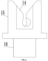
FIG. 1 is a perspective view of a vortex splicing nozzle according to an embodiment of the present disclosure; -
FIG. 2 is a front schematic diagram of the vortex splicing nozzle according to an embodiment of the present disclosure; -
FIG. 3 is a rear schematic diagram of the vortex splicing nozzle according to an embodiment of the present disclosure; -
FIG. 4 is a perspective view of a core; -
FIG. 5 is a front schematic diagram of the core; -
FIG. 6 is a right schematic diagram of the core; -
FIG. 7 is a schematic diagram of a housing; and -
FIG. 8 is an airflow simulation diagram of a vortex splicing nozzle near a splicing chamber according to an embodiment of the present disclosure. - Reference numerals: 1 first gripping chamber; 2 second gripping chamber; 3 first gas inlet hole; 4 second gas inlet hole; 5 first curved surface; 6 second curved surface; 7 plane; 8 V-shaped groove; 9 vertical groove; 10 square groove; 11 cylindrical groove; 12 first portion; 13 second portion; 14 core; 15 housing; 16 gas supply pipeline; 17 yarn.
- The following clearly and completely describes the technical solutions in the embodiments of the present disclosure with reference to the accompanying drawings in the embodiments of the present disclosure. Apparently, the described embodiments are merely a part rather than all of the embodiments of the present disclosure. All other embodiments obtained by a person of ordinary skill in the art based on the embodiments of the present disclosure without creative efforts shall fall within the protection scope of the present disclosure.
- An objective of the embodiments is to provide a vortex splicing nozzle to reduce the friction between yarns and a splicing chamber, thus increasing the twist of a portion at a position where the yarns are spliced, and further improving the tensile fracture strength of the portion at the position where the yarns are spliced and the overall aesthetics of the yarns.
- In order to make the objectives, technical solutions and advantages of the present disclosure more clearly, the present disclosure is further described in detail below with reference to the embodiments. In this embodiment, the splicing of two yarns are taken as an example for illustration. In actual use, the number of yarns may be more than three.
- Referring to
FIGs. 1 - 8 , a vortex splicing nozzle provided by this embodiment includes a splicing chamber. The splicing chamber includes two gripping chambers communicated with each other, the two gripping chambers includes afirst gripping chamber 1 and asecond gripping chamber 2, and the cross sections of the two gripping chambers are partially overlapped. Each gripping chamber is provided with gas inlet holes and curved surfaces opposite to the gas inlet holes, the curved surface is configured for guiding a gas introduced from the gas inlet hole as a one way rotating rotational flow, and rotating directions of rotational flows in the two gripping chambers are opposite. - A side wall of the gripping chamber is provided with a first
gas inlet hole 3 and a secondgas inlet hole 4, and the firstgas inlet hole 3 and the secondgas inlet hole 4 of the same gripping chamber are configured for forming rotational flows with the same rotating direction. The cross-sectional area of the firstgas inlet hole 3 is less than that of the secondgas inlet hole 4, so as to form a dragging airflow layer with higher flow velocity and a pushing airflow layer with lower flow velocity, and the dragging airflow layer is located at one side, close to the gripping chamber, of the pushing airflow layer. - The operation principle of the vortex splicing nozzle in this embodiment is as follows:
- The two
yarns 17 both penetrate through thefirst gripping chamber 1 and thesecond gripping chamber 2, and the twoyarns 17 are promoted to approach each other due to the cross sections of the two gripping chambers are partially overlapped. When airflows are introduced into the gripping chamber through the gas inlet holes, the twoyarns 17 are spliced. As the cross-sectional area of the firstgas inlet hole 3 is less than that of the secondgas inlet hole 4, a thickness of the rotational flow generated by the firstgas inlet hole 3 is less than that generated by the secondgas inlet hole 4, thus accelerating the flow velocity of the airflow near the inner wall of the gripping chamber, dividing the airflow into a dragging airflow layer and a pushing airflow layer. The dragging airflow layer can increase a gap between theyarns 17 and the gripping chamber, so that the friction between theyarns 17 and the gripping chamber is reduced, and the rotating speed of the airflow rotating around theyarns 17 is improved, thus increasing the twist of a portion at the position where the yarns are spliced, and further improving the tensile fracture strength of the portion at the position where the yarns are spliced. Furthermore, due to the increase of the twist of the portion at the position where theyarns 17 are spliced, the portion at the position where theyarns 17 are spliced is thinner, thus improving the overall aesthetics of theyarns 17. - As a possible example, in this embodiment, the curved surfaces of the gripping chamber includes a first
curved surface 5, and a secondcurved surface 6. The firstcurved surface 5 directly faces an outlet of the firstgas inlet hole 3, the secondcurved surface 6 directly faces an outlet of the secondgas inlet hole 4, the bottom of the firstcurved surface 5 is connected to the bottom of the secondcurved surface 6 via aplane 7, the outlet of the firstgas inlet hole 3 is located on theplane 7, and an opening is provided between the top of the firstcurved surface 5 and the top of the secondcurved surface 6. Specifically, in this embodiment, the firstcurved surface 5 is preferably a cylindrical surface. According to different actual needs, those of ordinary skill in the art may also choose gripping chambers in other shapes, for example, theplane 7 between the firstcurved surface 5 and the secondcurved surface 6 can be replaced with a transition curved surface. - As a possible example, in this embodiment, a V-shaped
groove 8 and avertical groove 9 for theyarns 17 to pass through is provided above the gripping chambers, the bottom of the V-shapedgroove 8 is connected to the top of thevertical groove 9, and the bottom of thevertical groove 9 is connected to the opening and deviated to one side of the gripping chamber. The side of an opening of the V-shapedgroove 8 gradually decreases from top to bottom, thus guiding theyarns 17 and making theyarns 17 enter the gripping chambers easier. - As a possible example, in this embodiment, the vortex splicing nozzle further includes a core 14, and a
housing 15. The gripping chambers are located in thecore 14, thehousing 15 is sleeved outside the core 14 to form a gas supply chamber between thehousing 15 and thecore 14. The gas supply chamber is communicated with multiple gas inlet holes. The gas supply mode in this embodiment, on the one hand, guarantees that the pressure in the firstgas inlet hole 3 is consistent with that in the secondgas inlet hole 4 and on the other hand, thus reducing the use of the pipeline and the joint, simplifying the structure and reducing the cost. - As a possible example, in this embodiment, the first
gas inlet hole 3 and the secondgas inlet hole 4 are both straight holes, which can be formed by drilling, thus reducing the processing cost. When the firstgas inlet hole 3 and the secondgas inlet hole 4 are curved holes, thecore 14 may be formed by casting, injection molding and other processing modes. The straight hole here is preferably a round hole, those skilled in the art may choose straight holes with other cross section shapes according to different actual needs. - As a possible example, in this embodiment, the first
gas inlet hole 3 and the secondgas inlet hole 4 are parallel to and opposite to each other. That is, compared with the directly facing position relationship, the firstgas inlet hole 3 and the secondgas inlet hole 4 are deviated from each other. According to different actual needs, those skilled in the art may also choose to form an included angle between the firstgas inlet hole 3 and the secondgas inlet hole 4, such as an included angle of 5 degrees or 10 degrees. - As a possible example, in this embodiment, the top of the
housing 15 is provided with asquare groove 10, the bottom of thehousing 15 is provided with acylindrical groove 11, and the bottom of thecore 14 is embedded into thesquare groove 10. An axis of thecylindrical groove 11 extends through a central face of thesquare groove 10 and is perpendicular to the bottom of thesquare groove 10, and thecylindrical groove 11 extends to groove walls on both sides of thesquare groove 10. Portions of thecylindrical groove 11 corresponding to the groove walls on both sides of thesquare groove 10 are a first portion12 and asecond portion 13. An inlet of the secondgas inlet hole 4 of the firstgripping chamber 1 directly faces the first portion 12, and an inlet of the secondgas inlet hole 4 of the secondgripping chamber 2 directly faces thesecond portion 13. An inlet of the firstgas inlet hole 3 is located on a bottom surface of thecore 14 and directly faces thecylindrical groove 11 at the bottom of thehousing 15. According to different actual needs, those of ordinary skill in the art may also choosehousings 15 andcores 14 in other shapes. - As a possible example, in this embodiment, the vortex splicing nozzle further includes a
gas supply pipeline 16 fixedly communicated with thehousing 15, a first end of thegas supply pipeline 16 is communicated with the gas supply chamber, and a second end of thegas supply pipeline 16 is communicated with a high-pressure gas source, so as to supply gas into the gas supply chamber. - Specific examples are used herein for illustration of the principles and implementation methods of the present disclosure. The description of the embodiments is merely used to help illustrate the method and its core principles of the present disclosure. In addition, a person of ordinary skill in the art can make various modifications in terms of specific embodiments and scope of application in accordance with the teachings of the present disclosure. In conclusion, the content of this specification shall not be construed as a limitation to the present disclosure.
Claims (8)
- A vortex splicing nozzle, comprising a splicing chamber, wherein the splicing chamber comprises two gripping chambers communicated with each other, cross sections of the two gripping chambers are partially overlapped, and each of the two gripping chambers is provided with gas inlet holes and curved surfaces opposite to the gas inlet holes; the curved surfaces are configured for guiding gases introduced from the gas inlet holes as one way rotating rotational flows, and rotating directions of rotational flows in the two gripping chambers are opposite, the vortex splicing nozzle being characterized in that
a side wall of the gripping chamber is provided with a first gas inlet hole and a second gas inlet hole, and the first gas inlet hole and the second gas inlet hole are configured for forming the rotational flows with a same rotating direction; cross sectional area of the first gas inlet hole is less than that of the second gas inlet hole, so as to form a dragging airflow layer with a higher flow velocity and a pushing airflow layer with a lower flow velocity, and the dragging airflow layer is located at one side, close to the gripping chamber, of the pushing airflow layer. - The vortex splicing nozzle according to claim 1, wherein the curved surfaces comprises a first curved surface and a second curved surface; the first curved surface directly faces an outlet of the first gas inlet hole, the second curved surface directly faces an outlet of the second gas inlet hole, a bottom of the first curved surface is connected to a bottom of the second curved surface via a plane, the outlet of the first gas inlet hole is located on the plane, and an opening is provided between a top of the first curved surface and a top of the second curved surface.
- The vortex splicing nozzle according to claim 2, wherein a V-shaped groove and a vertical groove for yarns to pass through are provided above the two gripping chambers, a bottom of the V-shaped groove is connected to a top of the vertical groove, and a bottom of the vertical groove is connected to the opening and deviated to one side of one of the two gripping chambers.
- The vortex splicing nozzle according to claim 2, further comprising a core, and a housing, wherein the two gripping chambers are located in the core, the housing is sleeved outside the core to form a gas supply chamber between the housing and the core, and the gas supply chamber is simultaneously communicated with the gas inlet holes.
- The vortex splicing nozzle according to claim 4, wherein each of the first gas inlet hole and the second gas inlet hole is a straight hole.
- The vortex splicing nozzle according to claim 5, wherein the first gas inlet hole and the second gas inlet hole are parallel to and opposite to each other.
- The vortex splicing nozzle according to claim 6, wherein a top of the housing is provided with a square groove, and a bottom of the housing is provided with a cylindrical groove, an axis of the cylindrical groove extends through a central face of the square groove and is perpendicular to a bottom of the square groove, the cylindrical groove extends to groove walls, on both sides, of the square groove, and the core is embedded into the square groove;an inlet of the second gas inlet hole of one of the two gripping chambers directly faces the cylindrical groove on one of the groove walls, at one side, of the square groove, and an inlet of the second gas inlet hole of an other of the two gripping chambers directly faces the cylindrical grooves on an other of the groove walls, at an other side, of the square groove; andan inlet of the first gas inlet hole is located on a bottom surface of the core, and directly faces the cylindrical groove at the bottom of the housing.
- The vortex splicing nozzle according to claim 4, further comprising a gas supply pipeline fixedly connected to the housing, wherein the gas supply pipeline is communicated with the gas supply chamber.
Applications Claiming Priority (1)
| Application Number | Priority Date | Filing Date | Title |
|---|---|---|---|
| CN202311666300.9A CN117533883B (en) | 2023-08-29 | 2023-12-06 | Vortex twisting block |
Publications (2)
| Publication Number | Publication Date |
|---|---|
| EP4566976A1 true EP4566976A1 (en) | 2025-06-11 |
| EP4566976B1 EP4566976B1 (en) | 2026-06-17 |
Family
ID=90675761
Family Applications (1)
| Application Number | Title | Priority Date | Filing Date |
|---|---|---|---|
| EP24166396.2A Active EP4566976B1 (en) | 2023-12-06 | 2024-03-26 | Vortex splicing nozzle |
Country Status (1)
| Country | Link |
|---|---|
| EP (1) | EP4566976B1 (en) |
Citations (2)
| Publication number | Priority date | Publication date | Assignee | Title |
|---|---|---|---|---|
| EP2666741A2 (en) * | 2012-05-25 | 2013-11-27 | Murata Machinery, Ltd. | Yarn splicing device, yarn splicing system, and textile machine |
| EP4071097A1 (en) * | 2021-04-09 | 2022-10-12 | Murata Machinery, Ltd. | Yarn splicing nozzle and winding device |
-
2024
- 2024-03-26 EP EP24166396.2A patent/EP4566976B1/en active Active
Patent Citations (2)
| Publication number | Priority date | Publication date | Assignee | Title |
|---|---|---|---|---|
| EP2666741A2 (en) * | 2012-05-25 | 2013-11-27 | Murata Machinery, Ltd. | Yarn splicing device, yarn splicing system, and textile machine |
| EP4071097A1 (en) * | 2021-04-09 | 2022-10-12 | Murata Machinery, Ltd. | Yarn splicing nozzle and winding device |
Also Published As
| Publication number | Publication date |
|---|---|
| EP4566976B1 (en) | 2026-06-17 |
Similar Documents
| Publication | Publication Date | Title |
|---|---|---|
| US4397137A (en) | Pneumatic yarn splicing | |
| CN201447265U (en) | Yarn joiner | |
| JP2009143718A (en) | Splicer nozzle | |
| EP4495490A1 (en) | Air duct structure and air conditioner having same | |
| CN115342001A (en) | Engine cylinder cover and gas engine | |
| CN208485993U (en) | An air-jet vortex spinning equipment | |
| IT8125555A1 (en) | Process and device for splicing two ends of yarn or thread | |
| ATE453456T1 (en) | HYDROCYCLONE | |
| US6928803B2 (en) | Textile processing machine with a fiber conveying channel and a fiber-guiding surface | |
| IT8448167A1 (en) | DEVICE FOR JOINING YARN THREADS | |
| CN1445396A (en) | Ducted cladding | |
| CN208649527U (en) | A kind of air injection air vortex spinning apparatus vortex tube | |
| CN203375770U (en) | Flow divider and air conditioner | |
| US4569193A (en) | Apparatus for producing a fasciated yarn | |
| TWI734497B (en) | Industrial apparatus and cyclone exhaust device | |
| CN201567406U (en) | Preset device for yarn splicer | |
| JP2023537099A (en) | Interlacing nozzle for producing knotted yarn and method for interlacing yarn | |
| CN102212908B (en) | Upper shell of air splicer with reliable twisting | |
| CN219141772U (en) | Measuring devices, assemblies, systems and processing machines for measuring workpiece surfaces | |
| GB1473612A (en) | Method and device for pneumatic false twisting | |
| CN212283239U (en) | Low pressure difference air filtering device | |
| CN115522304A (en) | Main nozzle capable of accelerating air jet loom | |
| CN216614974U (en) | Cyclone assembly for air splicing yarns | |
| CN2237053Y (en) | Network device | |
| CN220044896U (en) | A single-channel rotary joint for silk drying machine |
Legal Events
| Date | Code | Title | Description |
|---|---|---|---|
| PUAI | Public reference made under article 153(3) epc to a published international application that has entered the european phase |
Free format text: ORIGINAL CODE: 0009012 |
|
| STAA | Information on the status of an ep patent application or granted ep patent |
Free format text: STATUS: REQUEST FOR EXAMINATION WAS MADE |
|
| 17P | Request for examination filed |
Effective date: 20240422 |
|
| AK | Designated contracting states |
Kind code of ref document: A1 Designated state(s): AL AT BE BG CH CY CZ DE DK EE ES FI FR GB GR HR HU IE IS IT LI LT LU LV MC ME MK MT NL NO PL PT RO RS SE SI SK SM TR |
|
| GRAP | Despatch of communication of intention to grant a patent |
Free format text: ORIGINAL CODE: EPIDOSNIGR1 |
|
| STAA | Information on the status of an ep patent application or granted ep patent |
Free format text: STATUS: GRANT OF PATENT IS INTENDED |
|
| RIC1 | Information provided on ipc code assigned before grant |
Ipc: B65H 69/06 20060101AFI20251028BHEP |
|
| INTG | Intention to grant announced |
Effective date: 20251118 |
|
| GRAS | Grant fee paid |
Free format text: ORIGINAL CODE: EPIDOSNIGR3 |
|
| GRAA | (expected) grant |
Free format text: ORIGINAL CODE: 0009210 |
|
| STAA | Information on the status of an ep patent application or granted ep patent |
Free format text: STATUS: THE PATENT HAS BEEN GRANTED |
|
| AK | Designated contracting states |
Kind code of ref document: B1 Designated state(s): AL AT BE BG CH CY CZ DE DK EE ES FI FR GB GR HR HU IE IS IT LI LT LU LV MC ME MK MT NL NO PL PT RO RS SE SI SK SM TR |
|
| REG | Reference to a national code |
Ref country code: CH Ref legal event code: F10 Free format text: ST27 STATUS EVENT CODE: U-0-0-F10-F00 (AS PROVIDED BY THE NATIONAL OFFICE) Effective date: 20260617 Ref country code: GB Ref legal event code: FG4D |
|
| REG | Reference to a national code |
Ref country code: DE Ref legal event code: R096 Ref document number: 602024005439 Country of ref document: DE |
|
| REG | Reference to a national code |
Ref country code: IE Ref legal event code: FG4D |