EP4566957A1 - Sterilization apparatus for a packaging machine and packaging machine for forming packages - Google Patents
Sterilization apparatus for a packaging machine and packaging machine for forming packages Download PDFInfo
- Publication number
- EP4566957A1 EP4566957A1 EP24215173.6A EP24215173A EP4566957A1 EP 4566957 A1 EP4566957 A1 EP 4566957A1 EP 24215173 A EP24215173 A EP 24215173A EP 4566957 A1 EP4566957 A1 EP 4566957A1
- Authority
- EP
- European Patent Office
- Prior art keywords
- web
- packaging material
- pair
- rollers
- sterilization apparatus
- Prior art date
- Legal status (The legal status is an assumption and is not a legal conclusion. Google has not performed a legal analysis and makes no representation as to the accuracy of the status listed.)
- Pending
Links
Images


Classifications
-
- B—PERFORMING OPERATIONS; TRANSPORTING
- B65—CONVEYING; PACKING; STORING; HANDLING THIN OR FILAMENTARY MATERIAL
- B65B—MACHINES, APPARATUS OR DEVICES FOR, OR METHODS OF, PACKAGING ARTICLES OR MATERIALS; UNPACKING
- B65B55/00—Preserving, protecting or purifying packages or package contents in association with packaging
- B65B55/02—Sterilising, e.g. of complete packages
- B65B55/04—Sterilising wrappers or receptacles prior to, or during, packaging
- B65B55/10—Sterilising wrappers or receptacles prior to, or during, packaging by liquids or gases
- B65B55/103—Sterilising flat or tubular webs
-
- B—PERFORMING OPERATIONS; TRANSPORTING
- B65—CONVEYING; PACKING; STORING; HANDLING THIN OR FILAMENTARY MATERIAL
- B65B—MACHINES, APPARATUS OR DEVICES FOR, OR METHODS OF, PACKAGING ARTICLES OR MATERIALS; UNPACKING
- B65B9/00—Enclosing successive articles, or quantities of material, e.g. liquids or semiliquids, in flat, folded, or tubular webs of flexible sheet material; Subdividing filled flexible tubes to form packages
- B65B9/10—Enclosing successive articles, or quantities of material, in preformed tubular webs, or in webs formed into tubes around filling nozzles, e.g. extruded tubular webs
- B65B9/20—Enclosing successive articles, or quantities of material, in preformed tubular webs, or in webs formed into tubes around filling nozzles, e.g. extruded tubular webs the webs being formed into tubes in situ around the filling nozzles
Definitions
- the present invention relates to a sterilization apparatus for a packaging machine for forming packages of a pourable product, more specifically of a pourable food product.
- the present invention also relates to a packaging machine for forming packages of a pourable product, more specifically of a pourable food product.
- liquid or pourable food products such as fruit juice, UHT (ultra-high-temperature treated) milk, wine, tomato sauce, etc.
- UHT ultra-high-temperature treated milk
- wine tomato sauce
- etc. are sold in packages made of sterilized packaging material.
- a typical example is the parallelepiped-shaped package for liquid or pourable food products known as Tetra Brik Aseptic (registered trademark), which is made by sealing and folding a laminated packaging material.
- the packaging material has a multilayer structure comprising a base layer, e.g. of paper or cardboard, covered on both sides with layers of heat-seal plastic material, e.g. polyethylene.
- the packaging material also comprises a layer of oxygen-barrier material (an oxygen-barrier layer), e.g. an aluminum foil, which is superimposed on a layer of heat-seal plastic material, and is in turn covered with another layer of heat-seal plastic material forming the inner face of the package eventually contacting the food product.
- Packages of this sort are normally produced on fully automatic packaging apparatuses, which advance and sterilize a web of packaging material, which is then formed into a tube and filled with the pourable pre/sterilized product under aseptic conditions before its formation into individual sealed packages.
- some automatic packaging apparatuses also comprise a molding apparatus for molding the opening devices or at least portions of the opening device onto the web of packaging material prior to the formation of the packages.
- a typical automatic packaging apparatuses also comprise a sterilization apparatus operating by means of chemical sterilization and being arranged downstream of the molding apparatus so as to sterilize the packaging material.
- the Applicant has found that, even though, the known sterilization apparatuses achieve excellent working results, a desire is felt in the sector to further improve the known sterilization apparatuses, in particular by further improving the efficiency of removal of the chemical sterilization agent from the packaging material.
- Number 1 indicates as a whole a packaging machine for producing (sealed) packages 2 of a pourable product, more specifically of a pourable food product such as pasteurized milk, fruit juice, wine, tomato sauce, emulsions, beverages with pulp etc.
- a pourable food product such as pasteurized milk, fruit juice, wine, tomato sauce, emulsions, beverages with pulp etc.
- Each package 2 may comprise a main body 3 formed from a packaging material, more specifically a multilayer packaging material.
- each package 2 may comprise an opening device 4 connected to and/or protruding from main body 3.
- opening device 4 may be configured to allow for a controlled outpouring of the pourable product from package 2.
- each opening device 4 may be configured to allow to access and/or to outpour, in particular after a manipulation of the opening device, the pourable food product packaged within the respective package 2.
- the manipulation of the opening device can be reversible or irreversible.
- packaging machine 1 may produce packages 2, in particular the respective main bodies 3, from a web of packaging material 5.
- the packaging material may have a multilayer structure and may comprise at least a layer of fibrous material, such as e.g. a paper or cardboard layer, and at least two layers of heat-seal plastic material, e.g. polyethylene, interposing the layer of fibrous material in between one another.
- a layer of fibrous material such as e.g. a paper or cardboard layer
- heat-seal plastic material e.g. polyethylene
- packaging material more specifically web of packaging material 5
- gas- and light-barrier material e.g. aluminum foil or ethylene vinyl alcohol (EVOH) film
- packaging material more specifically web of packaging material 5
- the packaging material may comprise a first face 6 and a second face 7, in particular the first face 6 being the face of web of packaging material 5 defining the inner face of the formed package 2 eventually being in contact with the filled pourable food product.
- web of packaging material 5 may comprise a plurality of repeat units, more specifically successively arranged (and equally spaced) with respect to one another along web of packaging material 5.
- each repeat unit may form the basis of one respective package 2.
- packaging machine 1 may be configured to produce packages 2 from web of packaging material 5 such that each package 2 results from one respective repeat unit.
- each repeat unit may be defined by one respective pattern present on web of packaging material 5.
- the pattern may be substantially identical for all repeat units and may also differ in minor details from the other patterns - minor differences may e.g. be the presence of information tags indicating a production day, a production lot, personalized information or similar.
- packaging machine 1 may comprise:
- packaging machine 1 may comprise a molding apparatus arranged upstream of sterilization apparatus 9 along web advancement path P and being configured to mold at least a portion of opening device 4 onto web of packaging material 5, more specifically onto each repeat unit.
- the molding apparatus may be configured to mold each opening device 4 as a whole onto the respective repeat unit.
- the molding apparatus may mold only a portion of each opening device 4 onto the respective repeat unit.
- packaging machine 1 may be void of a molding apparatus and web of packaging material 5 may be already fed into packaging machine 1 together with opening devices 4 and/or the portions of opening devices 4.
- web of packaging material 5 comprises a plurality of cavities 10 resulting from the presence of opening device 4 and/or a portion of opening device 4.
- each cavity 10 is part of an inner space of the respective package 2. Accordingly, sterilization apparatus 9 is configured to sterilize web of packaging material 5 together with cavities 10.
- sterilization apparatus 9 is provided with means for improving the sterilization of web of packaging material 5.
- packaging machine 1 may also comprises:
- conveying device 6 may also be configured to advance tube 18 along a tube advancement path Q towards and at least partially through package forming unit 21.
- conveying device 6 may also be configured to advance tube 18 and any intermediate of tube 18 along tube advancement path Q.
- any configuration of web of packaging material 5 is meant prior to obtaining the tube structure and after folding of web of packaging material 5 has been started.
- the intermediates of tube 18 are a result of a gradual folding of web of packaging material 5 so as to obtain tube 18, in particular by overlapping opposite lateral edges of web of packaging material 5 with one another.
- conveying device 6 may also be configured to advance web of packaging material 5 at and/or within sterilization apparatus 9.
- isolation chamber 15 may be configured to protect inner environment 16 from an (hostile) outer environment.
- isolation chamber 15 may be configured to allow for forming, longitudinally sealing and filling tube 18 in a sterile inner environment 16.
- sterilization apparatus 9 may comprise a sterilization device configured to expose web of packaging material 5 to a chemical sterilization agent such as hydrogen peroxide during advancement along a sterilization portion P1 of advancement path P.
- a chemical sterilization agent such as hydrogen peroxide
- the sterilization device may comprise a bath configured to contain and/or containing the chemical sterilization agent and, in use, the web of packaging material 5 advances through the bath and the chemical sterilization agent when advancing along the sterilization portion P1.
- sterilization apparatus 9 may comprise a housing 22 having an inner space 23. Moreover, sterilization apparatus 9 may be configured to sterilize web of packaging material 5 within inner space 23.
- the sterilization device may be arranged within inner space 23.
- housing 22 may be connected to isolation chamber 15, in particular such that the sterilized web of packaging material 5 enters inner environment 16 directly from inner space 23 (so that web of packaging material 5 is not exposed to any possible contamination).
- housing 22 may comprise an inlet opening for receiving web of packaging material 5 to be sterilized (into inner space 23) and an outlet opening for discharging the sterilized web of packaging material 5 (out of inner space 23 and into inner environment 16).
- the sterilization device may be arranged within housing 22, more specifically downstream of the inlet opening and upstream of the outlet opening along advancement path P.
- sterilization apparatus 9 may further comprise a plurality of rollers defining a drying portion P2 of advancement path P being arranged downstream of sterilization portion P1.
- advancement of web of packaging material 3 along drying portion P2 allows removal of the chemical sterilization agent from web of packaging material 5.
- inner space 23 comprises a drying space. Drying space being defined as the portion of inner space 23 within which, in use, web of packaging material 5 advances when advancing along drying portion P2.
- sterilization apparatus 9 may further comprise heating means configured to control a temperature within the drying space ranging between 60°C to 90°C.
- sterilization apparatus 9 is provided with means that efficiently allow for removal of the chemical sterilization agent not only from the planar portions of web of packaging material 5, but also from cavities 10.
- the arrangement of the rollers of the plurality of rollers contributes to an efficient removal of the chemical sterilization agent.
- the plurality of rollers is arranged such that drying portion P2 comprises a first section P2a and a second section P2b transversal and/or inclined with respect to first section P2a.
- the plurality of rollers comprises a first deflection roller 30 arranged at a deflection station at which drying portion P2 changes from first section P2a to second section P2b.
- first deflection roller 30 is arranged such that the change from first section P2a to second section P2b results in centrifugal forces F1 acting on web of packaging material 5 at the deflection station, and, if present, on the chemical sterilization agent being placed within cavities 10, for removing residuals of the chemical agent from cavities 10.
- first section P2a may be defined by the plurality of rollers such that during advancement of web of packaging material 5 along first section P2a gravitational force F2 may act on the residues of the chemical sterilization agent being present within cavities 10. This furthermore improves the removal of the chemical sterilization agent from cavities 10.
- first deflection roller 30 may be arranged such that first section P2a and second section P2b and/or their respective imaginary linear extensions 31 define an acute angle ⁇ different from 90°.
- the plurality of rollers further comprises a second deflection roller 32 arranged upstream of first deflection roller 30 along the advancement path P and a third deflection roller 33 arranged downstream of first deflection roller 30 along advancement path P.
- the plurality of rollers is arranged downstream of the sterilization device along advancement path P.
- first section P2a may be defined between second deflection roller 32 and first deflection roller 30 and second section P2b may be defined between first deflection roller 30 and third deflection roller 33.
- first deflection roller 30 may define an auxiliary portion P2c of drying portion P2, in particular interposed between first section P2a and second section P2b, and more specifically also connecting first section P2a and second section P2b with one another.
- first section P2a, second section P2b and auxiliary portion P2c define a U-shape or a V-shape.
- second deflection roller 32 and third deflection roller 33 may be displaced from one another along at least a first direction D1.
- first deflection roller 30 may be displaced from at least one of second deflection roller 32 and third deflection roller 33, more specifically from second deflection roller 32 and third deflection roller 33, along a second direction D2 orthogonal to first direction D1.
- first deflection roller 30 may be displaced from at least one of second deflection roller 32 and third deflection roller 33 more specifically from second deflection roller 32 and third deflection roller 33, along first direction D1.
- each one of second deflection roller 32, third deflection roller 33 and first deflection roller 30 extend along respective longitudinal axes A.
- each longitudinal axis A defines also the respective rotation axis.
- third deflection roller 33 may be arranged above second deflection roller 32 and/or third deflection roller 33 and second deflection roller 32 may be spaced apart from one another along first direction D1, but not about second direction D2.
- longitudinal axes A may be parallel to one another.
- second direction D2 is orthogonal to longitudinal axes A or second direction D2 and first direction D1 are orthogonal to longitudinal axes A.
- first deflection roller 30, second deflection roller 32 and third deflection roller 33 is spaced apart from the other ones of first deflection roller 30, second deflection roller 32 and third deflection roller 33 along a direction parallel to longitudinal axes A.
- first section P2a and second section P2b may be inclined with respect to first direction D1.
- first direction D1 is not perpendicular to the respective portions of web of packaging material 5 advancing along respectively first section P2a and second section P2b.
- second deflection roller 32 may deflect, in use, the advancing web of packaging material 5 from an upstream section P2u of drying portion P2 to first section P2a and/or third deflection roller 33 may deflect, in use, the advancing web of packaging material 5 from second section P2b to a downstream section P2d of drying portion P2.
- second deflection roller 32 and third deflection roller 33 may be arranged such that the respective portion of web of packaging material 5 advancing, in use, along upstream section P2u and the respective portion of web of packaging material 5 advancing, in use, along downstream section P2d lie within a common plane H.
- sterilization apparatus 9 may also comprise a fourth deflection roller 34, preferentially arranged within housing 22, more specifically within inner space 23.
- fourth deflection roller 34 may be arranged downstream of third deflection roller 33 along advancement path P.
- fourth deflection roller 34 may be displaced from second deflection roller 32 and third deflection roller 33 along first direction D1, and advantageously also along second direction D2.
- fourth deflection roller 34 may be arranged adjacent to the outlet opening of housing 22.
- fourth deflection roller 34 may be configured to deflect the, in use, advancing web of packaging material 5 prior to feeding web of packaging material 5 out of inner space 23, and preferentially into inner environment 16.
- fourth deflection roller 34 may be configured to deflect web of packaging material 5 at an angle of substantially 90°.
- the plurality of rollers may comprise at least a first pair 40 of upstream squeegee rollers and a second pair 41 of downstream squeegee rollers arranged downstream of first pair 40 along drying portion P2.
- Each one of first pair 40 and second pair 41 may be configured to remove liquid, in particular parts of the chemical sterilization agent, from web of packaging material 5. More specifically, in use, web of packaging material 5 advances between the respective upstream squeegee rollers of first pair 40 and the respective downstream squeegee rollers of second pair 41 resulting thereby in a removal of at least parts of the chemical sterilization agent associated with web of packaging material 5.
- first pair 40 and second pair 41 it is possible to further improve the removal of the chemical sterilization agent.
- first pair 40 and second pair 41 may be displaced from one another along first direction D1, but advantageously not along second direction D2 and even more advantageously even not along a direction parallel to longitudinal axes A.
- the respective portions of web of packaging material 5 being interposed between the upstream squeegee rollers of first pair 40 and the downstream squeegee rollers of second pair 41 may lie within common plane H.
- first deflection roller 30 and third deflection roller 33 may be interposed between first pair 40 and second pair 41.
- first deflection roller 30 may be arranged downstream of first pair 40 along advancement path P and third deflection roller 33 may be arranged upstream of second pair 41 along advancement path P.
- second deflection roller 32 may define one of the upstream squeegee rollers of first pair 40.
- the plurality of rollers and/or first deflection roller 30 and/or second deflection roller 32 and/or third deflection roller 33 and/or fourth deflection roller 34 and/or one or more of the upstream squeegee rollers and/or one or more of the downstream squeegee rollers may comprises respective grooves defining respective spaces within which opening devices 4 and/or portions of opening devices may move.
- sterilization apparatus 9 may also comprise one or more gas nozzles 42, each one arranged at one respective blowing station along drying portion P2 and being configured to direct a stream of gas, such as a stream of a sterile gas or a stream of sterile air, against web of packaging material 5. Some or all of gas nozzles 42 may be placed such that the respective stream of gas may be directed into cavities 10.
- gas nozzles 42 may be placed such that the respective stream of gas may be directed into cavities 10.
- Gas nozzles 42 further contribute to a more efficient removal of the chemical sterilization agent from web of packaging material 5 and/or cavities 10.
- one gas nozzle 42 may be positioned upstream of first pair 40 and/or second deflection roller 32 and/or one, more specifically two, even more specifically exactly two, gas nozzle 42 may be interposed between first pair 40 and/or second deflection roller 32 and second pair 41.
- one gas nozzle 42 may be interposed between third deflection roller 33 and second pair 41 and/or one gas nozzle 42 may be interposed between first deflection roller 30 and third deflection roller 33, in particular this gas nozzle 42 and/or these gas nozzles 42 being configured to direct the respective stream of gas into cavities 10.
- sterilization apparatus 9 may also comprise one or more air blades, i.e. gas nozzles having an elongated opening area through which a substantially linear stream of gas is ejected.
- air blades i.e. gas nozzles having an elongated opening area through which a substantially linear stream of gas is ejected.
- at least one air blade may be arranged downstream of second pair 41.
- packaging machine 1 may also comprise a conditioning unit configured to define and control the atmosphere and conditions within inner environment 16 and/or inner space 23.
- the conditioning unit may be configured to maintain and control sterility of inner environment 16 and/or inner space 23.
- the conditioning unit may also be configured to control temperature and/or humidity and/or pressure.
- the conditioning unit may comprise the heating means.
- the conditioning unit may also be configured to maintain sterility within inner environment 16 and/or inner space 23.
- the conditioning unit may also be configured to control:
- the conditioning unit may be configured to control the first pressure to be larger than the second pressure.
- the conditioning unit may be configured to control the first pressure and the second pressure to be larger than ambient pressure.
- packaging machine 1 produces packages 2 of a pourable food product.
- packaging machine 1 forms tube 18 from web of packaging material 5, longitudinally seals tube 18, fills tube 18 with the pourable product and forms, transversally seals and transversally cuts tube 18 so as to obtain packages 2.
- web of packaging material 5 is sterilized, in particular by passing through the bath containing the chemical sterilization agent.
- the chemical sterilization agent is removed from web of packaging material 5, including cavities 10.
- Removal of the chemical sterilization agent is efficiently obtained by having first pair 40 and second pair 41 and/or by having gas nozzles 42.
- Removal of the chemical sterilization agent is also efficiently obtained by having first deflection roller 30 guaranteeing centrifugal forces F1.
- sterilization apparatus 9 allows for an efficient removal of the chemical sterilization agent from web of packaging material 5, including cavities 10.
- a further advantage relies on the use of first pair 40 and second pair 41, in particular in combination with gas nozzles 42 as this allows for an efficient removal of the chemical sterilization agent.
- Another advantage resides in the use of first deflection roller 30 as guaranteeing the presence of centrifugal forces acting on the chemical sterilization agent, which results in removal of the chemical sterilization agent from web of packaging material 5 having particular advantages with regard to removal of the chemical sterilization agent from cavities 10.
Landscapes
- Engineering & Computer Science (AREA)
- Mechanical Engineering (AREA)
- Apparatus For Disinfection Or Sterilisation (AREA)
- Containers And Plastic Fillers For Packaging (AREA)
Abstract
There is described a sterilization apparatus (9) configured to sterilize a web of packaging material (5); the sterilization apparatus (9) comprises a sterilization device configured to expose the web of packaging material (5) to a chemical sterilization agent during advancement along a sterilization portion (P1) of an advancement path (P), and a plurality of rollers (30, 31, 33) defining a drying portion (P2) of the advancement path (P) so that the chemical sterilization agent is removed from the web of packaging material (5); the plurality of rollers (30, 31, 32, 40, 41) comprises at least a first pair (40) of upstream squeegee rollers and a second pair (41) of downstream squeegee rollers arranged downstream of the first pair (40) of upstream squeegee rollers along the drying portion (P2); each one of the first pair (40) of upstream squeegee rollers and the second pair (41) of downstream squeegee rollers is configured to remove liquid from the web of packaging material (5); the sterilization apparatus (9) also comprises one or more gas nozzles (42), each gas nozzle (42) being arranged at one respective blowing station along the drying portion and being configured to direct a stream of gas against the web of packaging material.
Description
- The present invention relates to a sterilization apparatus for a packaging machine for forming packages of a pourable product, more specifically of a pourable food product.
- Advantageously, the present invention also relates to a packaging machine for forming packages of a pourable product, more specifically of a pourable food product.
- As is known, many liquid or pourable food products, such as fruit juice, UHT (ultra-high-temperature treated) milk, wine, tomato sauce, etc., are sold in packages made of sterilized packaging material.
- A typical example is the parallelepiped-shaped package for liquid or pourable food products known as Tetra Brik Aseptic (registered trademark), which is made by sealing and folding a laminated packaging material. The packaging material has a multilayer structure comprising a base layer, e.g. of paper or cardboard, covered on both sides with layers of heat-seal plastic material, e.g. polyethylene. In the case of aseptic packages for long-storage products, such as UHT milk, the packaging material also comprises a layer of oxygen-barrier material (an oxygen-barrier layer), e.g. an aluminum foil, which is superimposed on a layer of heat-seal plastic material, and is in turn covered with another layer of heat-seal plastic material forming the inner face of the package eventually contacting the food product.
- Packages of this sort are normally produced on fully automatic packaging apparatuses, which advance and sterilize a web of packaging material, which is then formed into a tube and filled with the pourable pre/sterilized product under aseptic conditions before its formation into individual sealed packages.
- It is known that some types of packages also comprise respective opening devices, which allow to be manipulated for accessing the pourable product.
- In order to provide the packages with the opening devices, some automatic packaging apparatuses also comprise a molding apparatus for molding the opening devices or at least portions of the opening device onto the web of packaging material prior to the formation of the packages.
- A typical automatic packaging apparatuses also comprise a sterilization apparatus operating by means of chemical sterilization and being arranged downstream of the molding apparatus so as to sterilize the packaging material.
- The Applicant has found that, even though, the known sterilization apparatuses achieve excellent working results, a desire is felt in the sector to further improve the known sterilization apparatuses, in particular by further improving the efficiency of removal of the chemical sterilization agent from the packaging material.
- It is an object of the present invention to provide an improved sterilization apparatus for a packaging machine.
- It is a further object of the present invention to provide an improved packaging machine having a sterilization apparatus.
- According to the present invention, there is provided a sterilization apparatus as claimed in
claim 1. - Preferred non-limiting embodiments of the sterilization apparatus are claimed in the respective dependent claims.
- According to the present invention, there is also provided a packaging machine as claimed in
claim 15. - A non-limiting embodiment of the present invention will be described by way of example with reference to the accompanying drawings, in which:
-
Figure 1 is a schematic view of a packaging machine according to the present invention, with parts removed for clarity; -
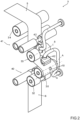
Figure 2 is a perspective view of a detail of the packaging machine ofFigure 1 , with parts removed for clarity; -
Figure 3 is a side view of the detail ofFigure 2 , with parts removed for clarity; and -
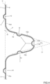
Figure 4 is a schematic view of a portion of an advancement path of a web of packaging material, with parts removed for clarity. -
Number 1 indicates as a whole a packaging machine for producing (sealed)packages 2 of a pourable product, more specifically of a pourable food product such as pasteurized milk, fruit juice, wine, tomato sauce, emulsions, beverages with pulp etc. - Each
package 2 may comprise a main body 3 formed from a packaging material, more specifically a multilayer packaging material. - Additionally, each
package 2 may comprise anopening device 4 connected to and/or protruding from main body 3. In particular,opening device 4 may be configured to allow for a controlled outpouring of the pourable product frompackage 2. - For example, each
opening device 4 may be configured to allow to access and/or to outpour, in particular after a manipulation of the opening device, the pourable food product packaged within therespective package 2. For example, the manipulation of the opening device can be reversible or irreversible. - In particular,
packaging machine 1 may producepackages 2, in particular the respective main bodies 3, from a web ofpackaging material 5. - In more detail, the packaging material, more specifically web of
packaging material 5, may have a multilayer structure and may comprise at least a layer of fibrous material, such as e.g. a paper or cardboard layer, and at least two layers of heat-seal plastic material, e.g. polyethylene, interposing the layer of fibrous material in between one another. One of these two layers of heat-seal plastic material defines the inner face ofpackage 2 eventually contacting the pourable product. - Moreover, the packaging material, more specifically web of
packaging material 5, may also comprise a layer of gas- and light-barrier material, e.g. aluminum foil or ethylene vinyl alcohol (EVOH) film, in particular being arranged between one of the layers of heat-seal plastic material and the layer of fibrous material. - Additionally, the packaging material, more specifically web of
packaging material 5, may also comprise a further layer of heat-seal plastic material being interposed between the layer of gas- and light-barrier material and the layer of fibrous material. - The packaging material, more specifically web of
packaging material 5, may comprise afirst face 6 and asecond face 7, in particular thefirst face 6 being the face of web ofpackaging material 5 defining the inner face of the formedpackage 2 eventually being in contact with the filled pourable food product. - In further detail, web of
packaging material 5 may comprise a plurality of repeat units, more specifically successively arranged (and equally spaced) with respect to one another along web ofpackaging material 5. - In more detail, each repeat unit may form the basis of one
respective package 2. In other words,packaging machine 1 may be configured to producepackages 2 from web ofpackaging material 5 such that eachpackage 2 results from one respective repeat unit. - In further detail, each repeat unit may be defined by one respective pattern present on web of
packaging material 5. For example, the pattern may be substantially identical for all repeat units and may also differ in minor details from the other patterns - minor differences may e.g. be the presence of information tags indicating a production day, a production lot, personalized information or similar. - With particular reference to
Figure 1 ,packaging machine 1 may comprise: - a conveying device 8 configured to advance web of
packaging material 5 along a web advancement path P; and - a
sterilization apparatus 9 configured to sterilize web ofpackaging material 5. - Additionally,
packaging machine 1 may comprise a molding apparatus arranged upstream ofsterilization apparatus 9 along web advancement path P and being configured to mold at least a portion ofopening device 4 onto web ofpackaging material 5, more specifically onto each repeat unit. - Preferentially but not necessarily, the molding apparatus may be configured to mold each
opening device 4 as a whole onto the respective repeat unit. Alternatively, the molding apparatus may mold only a portion of eachopening device 4 onto the respective repeat unit. - Alternatively,
packaging machine 1 may be void of a molding apparatus and web ofpackaging material 5 may be already fed intopackaging machine 1 together withopening devices 4 and/or the portions ofopening devices 4. - With reference to
Figure 4 , when, in use, enteringsterilization apparatus 9, web ofpackaging material 5 comprises a plurality ofcavities 10 resulting from the presence ofopening device 4 and/or a portion ofopening device 4. - It should be noted that after formation of the
respective packages 2, eachcavity 10 is part of an inner space of therespective package 2. Accordingly,sterilization apparatus 9 is configured to sterilize web ofpackaging material 5 together withcavities 10. - As will be discussed in more detail further below,
sterilization apparatus 9 is provided with means for improving the sterilization of web ofpackaging material 5. - In further detail and as schematically shown in
Figure 1 ,packaging machine 1 may also comprises: - an
isolation chamber 15 arranged downstream ofsterilization apparatus 9 and having aninner environment 16, more specifically a sterileinner environment 16; - a tube forming and
sealing device 17 configured to form within inner environment 16 atube 18 from the, in use, advancing web ofpackaging material 5 and to longitudinallyseal tube 18 withininner environment 16; - a
filling device 20 configured to filltube 18 with the pourable food product; and - a
package forming unit 21 configured to at least form and transversallyseal tube 18, preferentially to also transversally cuttube 18, for forming (sealed)packages 2. - Advantageously, conveying
device 6 may also be configured to advancetube 18 along a tube advancement path Q towards and at least partially throughpackage forming unit 21. - In further detail,
conveying device 6 may also be configured to advancetube 18 and any intermediate oftube 18 along tube advancement path Q. In particular, with intermediates oftube 18 any configuration of web ofpackaging material 5 is meant prior to obtaining the tube structure and after folding of web ofpackaging material 5 has been started. In other words, the intermediates oftube 18 are a result of a gradual folding of web ofpackaging material 5 so as to obtaintube 18, in particular by overlapping opposite lateral edges of web ofpackaging material 5 with one another. - Preferentially,
conveying device 6 may also be configured to advance web ofpackaging material 5 at and/or withinsterilization apparatus 9. - With particular reference to
Figure 1 ,isolation chamber 15 may be configured to protectinner environment 16 from an (hostile) outer environment. - Even more particular,
isolation chamber 15 may be configured to allow for forming, longitudinally sealing and fillingtube 18 in a sterileinner environment 16. - In further detail,
sterilization apparatus 9 may comprise a sterilization device configured to expose web ofpackaging material 5 to a chemical sterilization agent such as hydrogen peroxide during advancement along a sterilization portion P1 of advancement path P. - In more detail, the sterilization device may comprise a bath configured to contain and/or containing the chemical sterilization agent and, in use, the web of
packaging material 5 advances through the bath and the chemical sterilization agent when advancing along the sterilization portion P1. - In further detail,
sterilization apparatus 9 may comprise ahousing 22 having aninner space 23. Moreover,sterilization apparatus 9 may be configured to sterilize web ofpackaging material 5 withininner space 23. - More specifically, the sterilization device may be arranged within
inner space 23. - Advantageously,
housing 22 may be connected toisolation chamber 15, in particular such that the sterilized web ofpackaging material 5 entersinner environment 16 directly from inner space 23 (so that web ofpackaging material 5 is not exposed to any possible contamination). - In further detail,
housing 22 may comprise an inlet opening for receiving web ofpackaging material 5 to be sterilized (into inner space 23) and an outlet opening for discharging the sterilized web of packaging material 5 (out ofinner space 23 and into inner environment 16). - Advantageously, the sterilization device may be arranged within
housing 22, more specifically downstream of the inlet opening and upstream of the outlet opening along advancement path P. - With particular reference to
Figures 1 to 4 ,sterilization apparatus 9 may further comprise a plurality of rollers defining a drying portion P2 of advancement path P being arranged downstream of sterilization portion P1. - As will be explained in more detail further below, advancement of web of packaging material 3 along drying portion P2 allows removal of the chemical sterilization agent from web of
packaging material 5. - Preferentially but not necessarily,
inner space 23 comprises a drying space. Drying space being defined as the portion ofinner space 23 within which, in use, web ofpackaging material 5 advances when advancing along drying portion P2. - Advantageously,
sterilization apparatus 9 may further comprise heating means configured to control a temperature within the drying space ranging between 60°C to 90°C. - Preferentially,
sterilization apparatus 9 is provided with means that efficiently allow for removal of the chemical sterilization agent not only from the planar portions of web ofpackaging material 5, but also fromcavities 10. - Preferentially but not necessarily, the arrangement of the rollers of the plurality of rollers contributes to an efficient removal of the chemical sterilization agent.
- Preferentially but not necessarily, the plurality of rollers is arranged such that drying portion P2 comprises a first section P2a and a second section P2b transversal and/or inclined with respect to first section P2a.
- Moreover, the plurality of rollers comprises a
first deflection roller 30 arranged at a deflection station at which drying portion P2 changes from first section P2a to second section P2b. Moreover,first deflection roller 30 is arranged such that the change from first section P2a to second section P2b results in centrifugal forces F1 acting on web ofpackaging material 5 at the deflection station, and, if present, on the chemical sterilization agent being placed withincavities 10, for removing residuals of the chemical agent fromcavities 10. - This allows to render more efficient the removal of the chemical sterilization agent also from
cavities 10. - Additionally, first section P2a may be defined by the plurality of rollers such that during advancement of web of
packaging material 5 along first section P2a gravitational force F2 may act on the residues of the chemical sterilization agent being present withincavities 10. This furthermore improves the removal of the chemical sterilization agent fromcavities 10. - In more detail and with particular reference to
Figure 3 ,first deflection roller 30 may be arranged such that first section P2a and second section P2b and/or their respective imaginarylinear extensions 31 define an acute angle α different from 90°. - With particular reference to
Figures 2 and3 , the plurality of rollers, more specifically arranged withinhousing 22, even more specifically withininner space 23, further comprises asecond deflection roller 32 arranged upstream offirst deflection roller 30 along the advancement path P and athird deflection roller 33 arranged downstream offirst deflection roller 30 along advancement path P. - In particular, the plurality of rollers is arranged downstream of the sterilization device along advancement path P.
- For example, first section P2a may be defined between
second deflection roller 32 andfirst deflection roller 30 and second section P2b may be defined betweenfirst deflection roller 30 andthird deflection roller 33. - In further detail,
first deflection roller 30 may define an auxiliary portion P2c of drying portion P2, in particular interposed between first section P2a and second section P2b, and more specifically also connecting first section P2a and second section P2b with one another. - Preferentially but not necessarily, first section P2a, second section P2b and auxiliary portion P2c define a U-shape or a V-shape.
- According to some possible non-limiting embodiments,
second deflection roller 32 andthird deflection roller 33 may be displaced from one another along at least a first direction D1. - Additionally,
first deflection roller 30 may be displaced from at least one ofsecond deflection roller 32 andthird deflection roller 33, more specifically fromsecond deflection roller 32 andthird deflection roller 33, along a second direction D2 orthogonal to first direction D1. - Additionally,
first deflection roller 30 may be displaced from at least one ofsecond deflection roller 32 andthird deflection roller 33 more specifically fromsecond deflection roller 32 andthird deflection roller 33, along first direction D1. - In further detail, each one of
second deflection roller 32,third deflection roller 33 andfirst deflection roller 30 extend along respective longitudinal axes A. Advantageously, each longitudinal axis A defines also the respective rotation axis. - According to some preferred non-limiting embodiments,
third deflection roller 33 may be arranged abovesecond deflection roller 32 and/orthird deflection roller 33 andsecond deflection roller 32 may be spaced apart from one another along first direction D1, but not about second direction D2. - Advantageously, longitudinal axes A may be parallel to one another.
- Moreover, second direction D2 is orthogonal to longitudinal axes A or second direction D2 and first direction D1 are orthogonal to longitudinal axes A.
- Additionally, none of
first deflection roller 30,second deflection roller 32 andthird deflection roller 33 is spaced apart from the other ones offirst deflection roller 30,second deflection roller 32 andthird deflection roller 33 along a direction parallel to longitudinal axes A. - According to some possible solutions, first section P2a and second section P2b may be inclined with respect to first direction D1. In particular, first direction D1 is not perpendicular to the respective portions of web of
packaging material 5 advancing along respectively first section P2a and second section P2b. - In further detail,
second deflection roller 32 may deflect, in use, the advancing web ofpackaging material 5 from an upstream section P2u of drying portion P2 to first section P2a and/orthird deflection roller 33 may deflect, in use, the advancing web ofpackaging material 5 from second section P2b to a downstream section P2d of drying portion P2. - Advantageously,
second deflection roller 32 andthird deflection roller 33 may be arranged such that the respective portion of web ofpackaging material 5 advancing, in use, along upstream section P2u and the respective portion of web ofpackaging material 5 advancing, in use, along downstream section P2d lie within a common plane H. - According to the example shown in
Figures 1 to 4 ,sterilization apparatus 9 may also comprise afourth deflection roller 34, preferentially arranged withinhousing 22, more specifically withininner space 23. - More specifically,
fourth deflection roller 34 may be arranged downstream ofthird deflection roller 33 along advancement path P. - In further detail,
fourth deflection roller 34 may be displaced fromsecond deflection roller 32 andthird deflection roller 33 along first direction D1, and advantageously also along second direction D2. - According to some preferred non-limiting embodiments,
fourth deflection roller 34 may be arranged adjacent to the outlet opening ofhousing 22. - Moreover,
fourth deflection roller 34 may be configured to deflect the, in use, advancing web ofpackaging material 5 prior to feeding web ofpackaging material 5 out ofinner space 23, and preferentially intoinner environment 16. - According to some preferred non-limiting embodiments,
fourth deflection roller 34 may be configured to deflect web ofpackaging material 5 at an angle of substantially 90°. - Additionally or alternatively, the plurality of rollers may comprise at least a
first pair 40 of upstream squeegee rollers and asecond pair 41 of downstream squeegee rollers arranged downstream offirst pair 40 along drying portion P2. Each one offirst pair 40 andsecond pair 41 may be configured to remove liquid, in particular parts of the chemical sterilization agent, from web ofpackaging material 5. More specifically, in use, web ofpackaging material 5 advances between the respective upstream squeegee rollers offirst pair 40 and the respective downstream squeegee rollers ofsecond pair 41 resulting thereby in a removal of at least parts of the chemical sterilization agent associated with web ofpackaging material 5. By relying onfirst pair 40 andsecond pair 41 it is possible to further improve the removal of the chemical sterilization agent. - According to some preferred non-limiting embodiments,
first pair 40 andsecond pair 41 may be displaced from one another along first direction D1, but advantageously not along second direction D2 and even more advantageously even not along a direction parallel to longitudinal axes A. - In particular, in use, the respective portions of web of
packaging material 5 being interposed between the upstream squeegee rollers offirst pair 40 and the downstream squeegee rollers ofsecond pair 41 may lie within common plane H. - According to some preferred non-limiting embodiments,
first deflection roller 30 andthird deflection roller 33 may be interposed betweenfirst pair 40 andsecond pair 41. - More specifically,
first deflection roller 30 may be arranged downstream offirst pair 40 along advancement path P andthird deflection roller 33 may be arranged upstream ofsecond pair 41 along advancement path P. - According to the embodiment shown,
second deflection roller 32 may define one of the upstream squeegee rollers offirst pair 40. - According to some preferred non-limiting embodiments, the plurality of rollers and/or
first deflection roller 30 and/orsecond deflection roller 32 and/orthird deflection roller 33 and/orfourth deflection roller 34 and/or one or more of the upstream squeegee rollers and/or one or more of the downstream squeegee rollers may comprises respective grooves defining respective spaces within which openingdevices 4 and/or portions of opening devices may move. - With particular reference to
Figures 2 and3 ,sterilization apparatus 9 may also comprise one ormore gas nozzles 42, each one arranged at one respective blowing station along drying portion P2 and being configured to direct a stream of gas, such as a stream of a sterile gas or a stream of sterile air, against web ofpackaging material 5. Some or all ofgas nozzles 42 may be placed such that the respective stream of gas may be directed intocavities 10. -
Gas nozzles 42 further contribute to a more efficient removal of the chemical sterilization agent from web ofpackaging material 5 and/orcavities 10. - According to the specific example shown, one
gas nozzle 42 may be positioned upstream offirst pair 40 and/orsecond deflection roller 32 and/or one, more specifically two, even more specifically exactly two,gas nozzle 42 may be interposed betweenfirst pair 40 and/orsecond deflection roller 32 andsecond pair 41. - Additionally or alternatively, one
gas nozzle 42 may be interposed betweenthird deflection roller 33 andsecond pair 41 and/or onegas nozzle 42 may be interposed betweenfirst deflection roller 30 andthird deflection roller 33, in particular thisgas nozzle 42 and/or thesegas nozzles 42 being configured to direct the respective stream of gas intocavities 10. - Preferentially but not necessarily,
sterilization apparatus 9 may also comprise one or more air blades, i.e. gas nozzles having an elongated opening area through which a substantially linear stream of gas is ejected. For example at least one air blade may be arranged downstream ofsecond pair 41. - Additionally,
packaging machine 1 may also comprise a conditioning unit configured to define and control the atmosphere and conditions withininner environment 16 and/orinner space 23. In particular, the conditioning unit may be configured to maintain and control sterility ofinner environment 16 and/orinner space 23. Additionally, the conditioning unit may also be configured to control temperature and/or humidity and/or pressure. - Preferentially but not necessarily, the conditioning unit may comprise the heating means.
- Moreover, the conditioning unit may also be configured to maintain sterility within
inner environment 16 and/orinner space 23. - According to some preferred non-limiting embodiments, the conditioning unit may also be configured to control:
- a first pressure within
inner environment 16; and - a second pressure within
inner space 23. - Advantageously, the conditioning unit may be configured to control the first pressure to be larger than the second pressure.
- Moreover, the conditioning unit may be configured to control the first pressure and the second pressure to be larger than ambient pressure.
- In use,
packaging machine 1 producespackages 2 of a pourable food product. In particular, packagingmachine 1forms tube 18 from web ofpackaging material 5, longitudinally sealstube 18, fillstube 18 with the pourable product and forms, transversally seals andtransversally cuts tube 18 so as to obtainpackages 2. - Prior to the formation of
tube 18 from web ofpackaging material 5, web ofpackaging material 5 is sterilized bysterilization apparatus 9. - During advancement of web of
packaging material 5 along sterilization portion P1, web ofpackaging material 5 is sterilized, in particular by passing through the bath containing the chemical sterilization agent. - Moreover, during advancement along drying portion P2, the chemical sterilization agent is removed from web of
packaging material 5, includingcavities 10. - Removal of the chemical sterilization agent is efficiently obtained by having
first pair 40 andsecond pair 41 and/or by havinggas nozzles 42. - Removal of the chemical sterilization agent is also efficiently obtained by having
first deflection roller 30 guaranteeing centrifugal forces F1. - The advantages of
packaging machine 1 and/orsterilization apparatus 9 according to the present invention will be clear from the foregoing description. - In particular,
sterilization apparatus 9 allows for an efficient removal of the chemical sterilization agent from web ofpackaging material 5, includingcavities 10. - A further advantage relies on the use of
first pair 40 andsecond pair 41, in particular in combination withgas nozzles 42 as this allows for an efficient removal of the chemical sterilization agent. - Another advantage resides in the use of
first deflection roller 30 as guaranteeing the presence of centrifugal forces acting on the chemical sterilization agent, which results in removal of the chemical sterilization agent from web ofpackaging material 5 having particular advantages with regard to removal of the chemical sterilization agent fromcavities 10. - An even other advantage resides in that gravitational force acts on the chemical sterilization agent being present within
cavities 10, which allows draining of the chemical sterilization agent fromcavities 10. - Clearly, changes may be made to
packaging machine 1 and/orsterilization apparatus 9 as described herein without, however, departing from the scope of protection as defined in the accompanying claims.
Claims (15)
- Sterilization apparatus (9) for a packaging machine (1) for forming packages (2) filled with a pourable product from a web of packaging material (5) having a plurality of cavities (10);wherein the sterilization apparatus (9) is configured to sterilize the web of packaging material (5) during advancement of the web of packaging material (5) along an advancement path (P);wherein the sterilization apparatus (9) comprises:- a sterilization device configured to expose the web of packaging material (5) to a chemical sterilization agent during advancement along a sterilization portion (P1) of the advancement path (P); and- a plurality of rollers (30, 31, 33, 40, 41) defining a drying portion (P2) of the advancement path (P) being arranged downstream of the sterilization portion (P1) so that the chemical sterilization agent is removed from the web of packaging material (5) during advancement along the drying portion (P2);wherein the plurality of rollers (30, 31, 32, 40. 41) comprises at least a first pair (40) of upstream squeegee rollers and a second pair (41) of downstream squeegee rollers arranged downstream of the first pair (40) of upstream squeegee rollers along the drying portion (P2);wherein each one of the first pair (40) of upstream squeegee rollers and the second pair (41) of downstream squeegee rollers is configured to remove liquid from the web of packaging material (5);wherein the sterilization apparatus (9) also comprises one or more gas nozzles (42), each gas nozzle (42) being arranged at one respective blowing station along the drying portion and being configured to direct a stream of gas against the web of packaging material.
- Sterilization apparatus according to claim 1, wherein one gas nozzle (42) is positioned upstream of the first pair (40) of upstream squeegee rollers and one gas nozzle (42) is interposed between the first pair (40) of upstream squeegee rollers and the second pair (41) of downstream squeegee rollers.
- Sterilization apparatus according to claim 2, wherein two gas nozzles (42) are interposed between the first pair (40) of upstream squeegee rollers and the second pair (41) of downstream squeegee rollers.
- Sterilization apparatus according to any one of the preceding claims, wherein two deflection rollers (30, 33) are interposed between the first pair (40) of upstream squeegee rollers and the second pair (41) of downstream squeegee rollers;
wherein each deflection roller (30, 33) is configured to deflect the web of packaging material (5). - Sterilization apparatus according to claim 4, wherein one gas nozzle (42) is interposed between the two deflection rollers (30, 33) and/or one gas nozzle (42) is interposed between the second pair (41) of downstream squeegee rollers and the deflection rollers (30, 32).
- Sterilization apparatus according to any one of the preceding claims, wherein the first pair (40) of upstream squeegee rollers and the second pair (41) of downstream squeegee rollers are displaced from one another along a first direction (D1); and/or
in use, the respective portions of the web of packaging material (5) being interposed between the upstream squeegee rollers of the first pair (40) of upstream squeegee rollers and the downstream squeegee rollers of the second pair (41) of downstream squeegee rollers lie within a common plane (H) . - Sterilization apparatus according to any one of the preceding claims, wherein one of the upstream squeegee rollers of the first pair (40) of upstream squeegee rollers is a deflection roller (32) configured to deflect the, in use, advancing web of packaging material (5).
- Sterilization apparatus according to any one of the preceding claims, wherein the plurality of rollers (30, 31, 32, 40, 41) is arranged such that the drying portion (P2) comprises a first section (P2a) and a second section (P2b) transversal and/or inclined with respect to the first section (P2a) ;wherein the plurality of rollers (30, 31, 32, 40, 41) comprises a first deflection roller (30) arranged at a deflection station at which the drying portion (P2) changes from the first section (P2a) to the second section (P2b);wherein the first deflection roller (30) is interposed between the first pair (40) of squeegee roller and the second pair (41) of squeegee rollers.
- Sterilization apparatus according to claim 8, wherein the first section (P2a) is defined between one of the squeegee rollers of the first pair (40) of squeegee rollers and the first deflection roller (30) and the second section (P2b) is defined between the first deflection roller (30) and a further deflection roller (32) arranged downstream of the first deflection roller (30) and upstream of the second pair (41) of squeegee rollers.
- Sterilization apparatus according to claim 8 or 9, wherein the first deflection roller (30) is arranged such that the first section (P2a) and the second section (P2b) and/or their respective imaginary extensions (31) define an acute angle (α) different from 90°.
- Sterilization apparatus according to any one of the preceding claims, wherein the plurality of rollers (30, 31, 32, 40, 41) is arranged such that during advancement of web of packaging material (5) along a section (P2a) of drying portion (P2) gravitational force (F2) acting on the chemical sterilization agent present within the cavities (10) allows for draining of the chemical sterilization agent from the cavities (10).
- Sterilization apparatus according to any one of the preceding claims, wherein the web of packaging material (5) advances within a drying space of the sterilization apparatus (9) during advancement along the drying portion (P2) ;
wherein the sterilization apparatus (9) further comprises heating means configured to control a temperature within the drying space ranging between 60°C to 90°C. - Sterilization apparatus according to any one of the preceding claims, and further comprising a housing (22) having an inlet opening for receiving the web of packaging material (5) to be sterilized and an outlet opening for discharging the sterilized web of packaging material (5), wherein the sterilization device is arranged downstream of the inlet opening and/or upstream of the plurality of rollers (30, 31, 32, 40, 41).
- Sterilization apparatus according to any one of the preceding claims, wherein the sterilization device comprises a bath configured to contain the chemical sterilization agent and, in use, the web of packaging material (5) advances through the bath and the chemical sterilization agent.
- Packaging machine (1) for forming packages (2) filled with a pourable product, comprising:- a conveying device (8) configured to advance the web of packaging material (5) along a web advancement path (P);- an isolation chamber (15) having an inner environment (16) ;- a tube forming and sealing device (17) configured to form a tube (18) from the, in use, advancing web of packaging material (5) within the inner environment (16) and to longitudinally seal the tube (18) within the inner environment (16);- a filling device (20) for filling the tube (18) with the pourable product;- a package forming unit (21) configured to form, to transversally seal and to transversally cut the, in use, advancing tube (18) for forming the packages (2); and- a sterilization apparatus (9) according to any one of the preceding claims, being configured to sterilize the web of packaging material (5) and being arranged upstream of the isolation chamber (15).
Applications Claiming Priority (1)
| Application Number | Priority Date | Filing Date | Title |
|---|---|---|---|
| IT102023000026286A IT202300026286A1 (en) | 2023-12-07 | 2023-12-07 | STERILIZATION APPARATUS FOR A PACKAGING MACHINE AND PACKAGING MACHINE FOR FORMING PACKAGES |
Publications (1)
| Publication Number | Publication Date |
|---|---|
| EP4566957A1 true EP4566957A1 (en) | 2025-06-11 |
Family
ID=90123060
Family Applications (1)
| Application Number | Title | Priority Date | Filing Date |
|---|---|---|---|
| EP24215173.6A Pending EP4566957A1 (en) | 2023-12-07 | 2024-11-25 | Sterilization apparatus for a packaging machine and packaging machine for forming packages |
Country Status (3)
| Country | Link |
|---|---|
| EP (1) | EP4566957A1 (en) |
| IT (1) | IT202300026286A1 (en) |
| WO (1) | WO2025119689A1 (en) |
Citations (3)
| Publication number | Priority date | Publication date | Assignee | Title |
|---|---|---|---|---|
| DE2339128A1 (en) * | 1973-08-02 | 1975-02-20 | Bosch Gmbh Robert | Packaging material steriliser - for sterilising perishable foodstuff packaging |
| JPS6367225A (en) * | 1986-09-05 | 1988-03-26 | 凸版印刷株式会社 | Outer-surface foreign-matter removing device for packaging vessel blank |
| EP1759998A1 (en) * | 2005-08-30 | 2007-03-07 | Tetra Laval Holdings & Finance SA | Packaging method and machine for producing sealed packages of pourable food products |
-
2023
- 2023-12-07 IT IT102023000026286A patent/IT202300026286A1/en unknown
-
2024
- 2024-11-25 WO PCT/EP2024/083452 patent/WO2025119689A1/en active Pending
- 2024-11-25 EP EP24215173.6A patent/EP4566957A1/en active Pending
Patent Citations (3)
| Publication number | Priority date | Publication date | Assignee | Title |
|---|---|---|---|---|
| DE2339128A1 (en) * | 1973-08-02 | 1975-02-20 | Bosch Gmbh Robert | Packaging material steriliser - for sterilising perishable foodstuff packaging |
| JPS6367225A (en) * | 1986-09-05 | 1988-03-26 | 凸版印刷株式会社 | Outer-surface foreign-matter removing device for packaging vessel blank |
| EP1759998A1 (en) * | 2005-08-30 | 2007-03-07 | Tetra Laval Holdings & Finance SA | Packaging method and machine for producing sealed packages of pourable food products |
Also Published As
| Publication number | Publication date |
|---|---|
| IT202300026286A1 (en) | 2025-06-07 |
| WO2025119689A1 (en) | 2025-06-12 |
Similar Documents
| Publication | Publication Date | Title |
|---|---|---|
| EP2695816B1 (en) | Valve for controlling an air flow | |
| CN101316760B (en) | Packaging material sterilizing unit for a pourable food product packaging machine | |
| CN113453987B (en) | Packaging machine and method for producing sealed packages | |
| EP3656686B1 (en) | A packaging apparatus for forming sealed packages | |
| CN113710581A (en) | Packaging machine and method for producing sealed packages | |
| US20240010374A1 (en) | Infeed conveyor for a folding apparatus, folding apparatus having an infeed conveyor and packaging machine having a folding apparatus | |
| US20220177173A1 (en) | Packaging machine for producing sealed packages | |
| JP7787871B2 (en) | Package forming unit, packaging device having package forming unit, and package forming method | |
| US20210139180A1 (en) | Sterilization apparatus, packaging machine having a sterilization apparatus and a method for sterilizing | |
| EP4332008A1 (en) | Packaging machine and method for forming packages | |
| EP4570675A1 (en) | Sterilization apparatus for a packaging machine and packaging machine for forming packages | |
| WO2025119689A1 (en) | Sterilization apparatus for a packaging machine and packaging machine for forming packages | |
| EP4183693B1 (en) | Buffer unit for a packaging apparatus, packaging apparatus and method for producing sealed packages | |
| US20250250057A1 (en) | Packaging blank and package | |
| EP4219321B1 (en) | Packaging machine and method for forming packages | |
| CN113412220A (en) | Packaging machine and method for producing sealed packages | |
| EP4549329A1 (en) | Package forming apparatus for a packaging machine and packaging machine for forming packages filled with a pourable product | |
| EP4410690A1 (en) | Package forming apparatus for a packaging machine and packaging machine for forming packages filled with a pourable product | |
| WO2025247748A1 (en) | Infeed conveyor for a folding apparatus, folding apparatus having an infeed conveyor and packaging machine having a folding apparatus for forming finalized packages from semi-finalized packs | |
| WO2025113830A1 (en) | Packaging machine and method of cleaning a packaging machine | |
| WO2025185930A1 (en) | Sterilizing agent removal assembly for a packaging apparatus configured to produce sealed packages containing a pourable product | |
| IT202300008166A1 (en) | APPARATUS FOR FORMING PACKAGES FOR A PACKAGING MACHINE, PACKAGING MACHINE FOR FORMING PACKAGES FILLED WITH A POURABLE PRODUCT AND METHOD FOR FORMING PACKAGES | |
| HK1126175B (en) | Packaging material sterilizing unit for a pourable food product packaging machine |
Legal Events
| Date | Code | Title | Description |
|---|---|---|---|
| PUAI | Public reference made under article 153(3) epc to a published international application that has entered the european phase |
Free format text: ORIGINAL CODE: 0009012 |
|
| STAA | Information on the status of an ep patent application or granted ep patent |
Free format text: STATUS: THE APPLICATION HAS BEEN PUBLISHED |
|
| AK | Designated contracting states |
Kind code of ref document: A1 Designated state(s): AL AT BE BG CH CY CZ DE DK EE ES FI FR GB GR HR HU IE IS IT LI LT LU LV MC ME MK MT NL NO PL PT RO RS SE SI SK SM TR |
|
| STAA | Information on the status of an ep patent application or granted ep patent |
Free format text: STATUS: REQUEST FOR EXAMINATION WAS MADE |
|
| 17P | Request for examination filed |
Effective date: 20251211 |