EP4219321B1 - Packaging machine and method for forming packages - Google Patents
Packaging machine and method for forming packages Download PDFInfo
- Publication number
- EP4219321B1 EP4219321B1 EP23152919.9A EP23152919A EP4219321B1 EP 4219321 B1 EP4219321 B1 EP 4219321B1 EP 23152919 A EP23152919 A EP 23152919A EP 4219321 B1 EP4219321 B1 EP 4219321B1
- Authority
- EP
- European Patent Office
- Prior art keywords
- web
- packaging material
- station
- tube
- molding
- Prior art date
- Legal status (The legal status is an assumption and is not a legal conclusion. Google has not performed a legal analysis and makes no representation as to the accuracy of the status listed.)
- Active
Links
- 238000004806 packaging method and process Methods 0.000 title claims description 45
- 238000000034 method Methods 0.000 title claims description 17
- 239000005022 packaging material Substances 0.000 claims description 129
- 238000000465 moulding Methods 0.000 claims description 69
- 230000001954 sterilising effect Effects 0.000 claims description 66
- 238000004659 sterilization and disinfection Methods 0.000 claims description 58
- 239000012530 fluid Substances 0.000 claims description 33
- 238000007664 blowing Methods 0.000 claims description 22
- 238000007789 sealing Methods 0.000 claims description 17
- 235000013305 food Nutrition 0.000 claims description 13
- 230000036512 infertility Effects 0.000 claims description 13
- 238000002955 isolation Methods 0.000 claims description 13
- 230000003749 cleanliness Effects 0.000 claims description 9
- 238000010894 electron beam technology Methods 0.000 claims description 7
- 230000015572 biosynthetic process Effects 0.000 claims description 6
- 230000000249 desinfective effect Effects 0.000 claims description 5
- 238000005520 cutting process Methods 0.000 claims description 2
- 239000000463 material Substances 0.000 description 10
- 239000004033 plastic Substances 0.000 description 8
- 229920003023 plastic Polymers 0.000 description 8
- 238000011144 upstream manufacturing Methods 0.000 description 6
- 230000000712 assembly Effects 0.000 description 4
- 238000000429 assembly Methods 0.000 description 4
- 230000003750 conditioning effect Effects 0.000 description 4
- 239000002657 fibrous material Substances 0.000 description 4
- 239000000543 intermediate Substances 0.000 description 3
- 239000000126 substance Substances 0.000 description 3
- 241000227653 Lycopersicon Species 0.000 description 2
- 235000007688 Lycopersicon esculentum Nutrition 0.000 description 2
- 239000004698 Polyethylene Substances 0.000 description 2
- XAGFODPZIPBFFR-UHFFFAOYSA-N aluminium Chemical compound [Al] XAGFODPZIPBFFR-UHFFFAOYSA-N 0.000 description 2
- 229910052782 aluminium Inorganic materials 0.000 description 2
- 230000003139 buffering effect Effects 0.000 description 2
- 239000011111 cardboard Substances 0.000 description 2
- 239000011888 foil Substances 0.000 description 2
- 235000015203 fruit juice Nutrition 0.000 description 2
- 239000007788 liquid Substances 0.000 description 2
- 238000004519 manufacturing process Methods 0.000 description 2
- 239000011087 paperboard Substances 0.000 description 2
- -1 polyethylene Polymers 0.000 description 2
- 229920000573 polyethylene Polymers 0.000 description 2
- 238000004080 punching Methods 0.000 description 2
- 230000002441 reversible effect Effects 0.000 description 2
- 235000015067 sauces Nutrition 0.000 description 2
- 235000014101 wine Nutrition 0.000 description 2
- 235000013361 beverage Nutrition 0.000 description 1
- 239000000356 contaminant Substances 0.000 description 1
- 238000011109 contamination Methods 0.000 description 1
- 238000010924 continuous production Methods 0.000 description 1
- 230000001419 dependent effect Effects 0.000 description 1
- 230000008021 deposition Effects 0.000 description 1
- 239000000839 emulsion Substances 0.000 description 1
- 238000005265 energy consumption Methods 0.000 description 1
- 239000004715 ethylene vinyl alcohol Substances 0.000 description 1
- 230000002427 irreversible effect Effects 0.000 description 1
- 235000020191 long-life milk Nutrition 0.000 description 1
- 235000013336 milk Nutrition 0.000 description 1
- 239000008267 milk Substances 0.000 description 1
- 210000004080 milk Anatomy 0.000 description 1
- 235000020200 pasteurised milk Nutrition 0.000 description 1
- 229920000642 polymer Polymers 0.000 description 1
- 238000003860 storage Methods 0.000 description 1
- 238000009281 ultraviolet germicidal irradiation Methods 0.000 description 1
Images
Classifications
-
- B—PERFORMING OPERATIONS; TRANSPORTING
- B65—CONVEYING; PACKING; STORING; HANDLING THIN OR FILAMENTARY MATERIAL
- B65B—MACHINES, APPARATUS OR DEVICES FOR, OR METHODS OF, PACKAGING ARTICLES OR MATERIALS; UNPACKING
- B65B55/00—Preserving, protecting or purifying packages or package contents in association with packaging
- B65B55/02—Sterilising, e.g. of complete packages
- B65B55/04—Sterilising wrappers or receptacles prior to, or during, packaging
- B65B55/10—Sterilising wrappers or receptacles prior to, or during, packaging by liquids or gases
- B65B55/103—Sterilising flat or tubular webs
-
- B—PERFORMING OPERATIONS; TRANSPORTING
- B65—CONVEYING; PACKING; STORING; HANDLING THIN OR FILAMENTARY MATERIAL
- B65B—MACHINES, APPARATUS OR DEVICES FOR, OR METHODS OF, PACKAGING ARTICLES OR MATERIALS; UNPACKING
- B65B55/00—Preserving, protecting or purifying packages or package contents in association with packaging
- B65B55/02—Sterilising, e.g. of complete packages
- B65B55/04—Sterilising wrappers or receptacles prior to, or during, packaging
- B65B55/08—Sterilising wrappers or receptacles prior to, or during, packaging by irradiation
-
- B—PERFORMING OPERATIONS; TRANSPORTING
- B65—CONVEYING; PACKING; STORING; HANDLING THIN OR FILAMENTARY MATERIAL
- B65B—MACHINES, APPARATUS OR DEVICES FOR, OR METHODS OF, PACKAGING ARTICLES OR MATERIALS; UNPACKING
- B65B61/00—Auxiliary devices, not otherwise provided for, for operating on sheets, blanks, webs, binding material, containers or packages
- B65B61/18—Auxiliary devices, not otherwise provided for, for operating on sheets, blanks, webs, binding material, containers or packages for making package-opening or unpacking elements
- B65B61/186—Auxiliary devices, not otherwise provided for, for operating on sheets, blanks, webs, binding material, containers or packages for making package-opening or unpacking elements by applying or incorporating rigid fittings, e.g. discharge spouts
-
- B—PERFORMING OPERATIONS; TRANSPORTING
- B65—CONVEYING; PACKING; STORING; HANDLING THIN OR FILAMENTARY MATERIAL
- B65B—MACHINES, APPARATUS OR DEVICES FOR, OR METHODS OF, PACKAGING ARTICLES OR MATERIALS; UNPACKING
- B65B9/00—Enclosing successive articles, or quantities of material, e.g. liquids or semiliquids, in flat, folded, or tubular webs of flexible sheet material; Subdividing filled flexible tubes to form packages
- B65B9/10—Enclosing successive articles, or quantities of material, in preformed tubular webs, or in webs formed into tubes around filling nozzles, e.g. extruded tubular webs
- B65B9/20—Enclosing successive articles, or quantities of material, in preformed tubular webs, or in webs formed into tubes around filling nozzles, e.g. extruded tubular webs the webs being formed into tubes in situ around the filling nozzles
-
- A—HUMAN NECESSITIES
- A61—MEDICAL OR VETERINARY SCIENCE; HYGIENE
- A61L—METHODS OR APPARATUS FOR STERILISING MATERIALS OR OBJECTS IN GENERAL; DISINFECTION, STERILISATION OR DEODORISATION OF AIR; CHEMICAL ASPECTS OF BANDAGES, DRESSINGS, ABSORBENT PADS OR SURGICAL ARTICLES; MATERIALS FOR BANDAGES, DRESSINGS, ABSORBENT PADS OR SURGICAL ARTICLES
- A61L2/00—Methods or apparatus for disinfecting or sterilising materials or objects other than foodstuffs or contact lenses; Accessories therefor
- A61L2/02—Methods or apparatus for disinfecting or sterilising materials or objects other than foodstuffs or contact lenses; Accessories therefor using physical phenomena
- A61L2/08—Radiation
- A61L2/087—Particle radiation, e.g. electron-beam, alpha or beta radiation
-
- A—HUMAN NECESSITIES
- A61—MEDICAL OR VETERINARY SCIENCE; HYGIENE
- A61L—METHODS OR APPARATUS FOR STERILISING MATERIALS OR OBJECTS IN GENERAL; DISINFECTION, STERILISATION OR DEODORISATION OF AIR; CHEMICAL ASPECTS OF BANDAGES, DRESSINGS, ABSORBENT PADS OR SURGICAL ARTICLES; MATERIALS FOR BANDAGES, DRESSINGS, ABSORBENT PADS OR SURGICAL ARTICLES
- A61L2/00—Methods or apparatus for disinfecting or sterilising materials or objects other than foodstuffs or contact lenses; Accessories therefor
- A61L2/02—Methods or apparatus for disinfecting or sterilising materials or objects other than foodstuffs or contact lenses; Accessories therefor using physical phenomena
- A61L2/08—Radiation
- A61L2/10—Ultraviolet radiation
Definitions
- the present invention relates to a packaging machine for forming packages filled with a pourable food product from a web of packaging material, in particular a web of packaging material having a multilayer structure.
- the packaging machine comprises a molding apparatus for molding molded portions, in particular opening devices, onto the web of packaging material.
- liquid or pourable food products such as fruit juice, UHT (ultra-high-temperature treated) milk, wine, tomato sauce, etc.
- UHT ultra-high-temperature treated milk
- wine tomato sauce
- etc. are sold in packages made of sterilized packaging material.
- a typical example is the parallelepiped-shaped package for liquid or pourable food products known as Tetra Brik Aseptic (registered trademark), which is made by sealing and folding a laminated packaging material.
- the packaging material has a multilayer structure comprising a base layer, e.g. of paper or cardboard, covered on both sides with layers of heat-seal plastic material, e.g. polyethylene.
- the packaging material also comprises a layer of oxygen-barrier material (an oxygen-barrier layer), e.g. an aluminum foil, which is superimposed on a layer of heat-seal plastic material, and is in turn covered with another layer of heat-seal plastic material forming the inner face of the package eventually contacting the food product.
- Packages of this sort are normally produced on fully automatic packaging apparatuses, which advance and sterilize a web of packaging material, which is then formed into a tube and filled with the pourable pre/sterilized product under aseptic conditions before its formation into individual sealed packages.
- a packaging machine is known, for example, in EP3549613A1 , which discloses a packaging machine for forming packages filled with a pourable product from a web of packaging material,the packaging machine comprises a conveying device configured to advance the web of packaging material along a web advancement path, a sterilization apparatus for sterilizing the web of packaging material and being arranged at a sterilization station along the web advancement path, an isolation chamber having an inner environment, a tube forming and sealing device configured to form a tube from the, in use, advancing web of packaging material within the inner environment at a tube formation station arranged downstream of the and to longitudinally seal the tube within the inner environment, a filling device for filling the tube with the pourable product, a package forming apparatus configured to form, to transversally seal and
- some automatic packaging apparatuses also comprise a molding apparatus for molding the opening devices onto the web of packaging material prior to the formation of the packages.
- the automatic packaging apparatus may comprise an isolation chamber within which the web of packaging material is formed and filled with the pourable product. As the web of packaging material gets into contact with the pourable product one needs to guarantee the cleanliness and/or sterility of the isolation chamber and of the web of packaging material.
- the typical automatic packaging apparatuses also comprise a sterilization apparatus arranged downstream of the molding apparatus and upstream of the isolation chamber so as to sterilize the packaging material.
- sterilization apparatuses can be configured to sterilize the web of packaging material by means of chemical sterilization or by physical sterilization.
- the Applicant has successfully established the use of the electron beam technology so as to sterilize the web of packaging material. While the sterilization of the flat web of packaging material by means of the electron beam technology is relatively easy, the situation becomes more challenging in the case of the presence of opening devices, which have been applied onto the web of packaging material. When sterilizing the web of packaging material being equipped with the opening devices, one may need to operate with rather high powers so as to obtain the desired sterility.
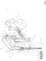
- Figure 1 is a schematic view of a packaging machine according to the present invention, with parts removed for clarity.
- Number 1 indicates as a whole a packaging machine for producing (sealed) packages 2 of a pourable food product such as pasteurized milk, fruit juice, wine, tomato sauce, emulsions, beverages with pulp etc.
- a pourable food product such as pasteurized milk, fruit juice, wine, tomato sauce, emulsions, beverages with pulp etc.
- Each packaging 2 may comprise a main body 3 and a molded portion 4, in particular an opening device, molded onto main body 3.
- packaging machine 1 may produce packages 2, in particular the respective main bodies 3, from a web of packaging material 5.
- web of packaging material 5 may have a multilayer structure and may comprise at least a layer of fibrous material, such as e.g. a paper or cardboard layer, and at least two layers of heat-seal plastic material, e.g. polyethylene, interposing the layer of fibrous material in between one another.
- a layer of fibrous material such as e.g. a paper or cardboard layer
- heat-seal plastic material e.g. polyethylene
- web of packaging material 5 also comprises a layer of gas- and light-barrier material, e.g. aluminum foil or ethylene vinyl alcohol (EVOH) film, in particular being arranged between one of the layers of the heat-seal plastic material and the layer of fibrous material.
- gas- and light-barrier material e.g. aluminum foil or ethylene vinyl alcohol (EVOH) film
- web of packaging material 5 may also comprise a further layer of heat-seal plastic material being interposed between the layer of gas- and light-barrier material and the layer of fibrous material.
- Web of packaging material 5 may comprise a first face and a second face, in particular the first face being the face of web of packaging material 5 defining the inner face of the formed package 2 eventually contacting the filled pourable food product.
- web of packaging material 5 may comprise a plurality of repeat units, in particular successively arranged (and equally spaced) with respect to one another along web of packaging material 5.
- each repeat unit may form the basis of one respective package 2.
- packaging machine 1 may be configured to produce packages 2 from web of packaging material 5 such that each package 2 results from one respective repeat unit.
- each repeat unit may be defined by one respective pattern present on web of packaging material 5.
- the pattern is substantially identical for all repeat units and may also differ in minor details from the other ones - minor differences may e.g. be the presence of information tags indicating a production day, a production lot, personalized information or similar.
- packaging machine 1 comprises:
- molded portions 4 are clean and/or sterile as a consequence of a number of factors including the high temperatures of plastic processing conditions needed during the molding process itself. Therefore, the Applicant wants to preserve (partially or in full) the cleanliness and/or sterility of molded portions 4 during advancement of web of packaging material 5 from molding station 8 to sterilization station 10.
- packaging machine1 also comprises a preserving device 22 configured to preserve the cleanliness and/or sterility of molded portions 4, in particular opening devices, in particular after molding.
- preserving device 22 is configured to preserve the cleanliness and/or sterility of molded portions 4, in particular opening devices, during advancement of web of packaging material 5 between molding station 8 and sterilization station 10.
- molding apparatus 7 molds at least one respective molded portion 4, in particular one respective opening device, onto each repeat unit of web of packaging material 3.
- molding apparatus 7 is configured to mold molded portions 4 from a molten polymer.
- molding apparatus 7 molds opening devices onto web of packaging material 3.
- each opening device may be configured to allow to access and/or to outpour, in particular after a manipulation of the opening device, the pourable food product packaged within the respective package 2.
- the manipulation of the opening device can be reversible or irreversible.
- an opening device is a lid-spout assembly, which comprises a spout and a lid, which is configured to selectively close and open a pouring outlet of the spout.
- a lid-spout assembly which comprises a spout and a lid, which is configured to selectively close and open a pouring outlet of the spout.
- removal of the lid is required, which typically is reversible, meaning that the lid can be newly coupled to the spout.
- an opening device is a strip, which can be removed from the respective package 2 for creating an outlet hole and/or for allowing to at least partially separating two portions of the respective package 2 from one another.
- molding apparatus 7 may comprise one or more molding units 11 each one configured to mold one or more molded portions 4, in particular one or more opening devices (at a time) onto web of packaging material 5, in particular onto at least one respective repeat unit.
- molding apparatus 7 may comprise one or more punching units configured to punch holes in web of packaging material 5, in particular prior to the operation of the one or more molding units 11.
- the punching unit may be arranged upstream of molding apparatuses 20 along web advancement path P.
- the one or more molding units 11 may be configured to mold molded portions 4, in particular the opening devices, onto web of packaging material 5 at the holes.
- conveying device 6 may also be configured to advance tube 18 along a tube advancement path Q towards and at least partially through package forming apparatus 21.
- conveying device 6 may also be configured to advance tube 18 and any intermediate of tube 18 along tube advancement path Q.
- any configuration of web of packaging material 5 is meant prior to obtaining the tube structure and after folding of web of packaging material 5 has been started.
- the intermediates of tube 18 are a result of a gradual folding of web of packaging material 5 so as to obtain tube 18, in particular by overlapping opposite lateral edges of web of packaging material 5 with one another.
- conveying device 6 may also be configured to advance web of packaging material 5 at and/or within molding apparatus 7 intermittently.
- conveying device 6 may be configured to intermittently advance and stop web of packaging material 5, and in particular each molding unit 11 may be configured to mold the respective molded portions 4 during a stop of web of packaging material 5.
- conveying device 6 may be configured to intermittently advance web of packaging material 5 along a molding portion P1 of path P.
- packaging machine 1 may also comprise a first buffer unit and a second buffer unit 24 arranged respectively upstream and downstream of molding station 8 along web advancement path P.
- the buffer capacity of the first buffer unit and second buffer unit 24 can be (dynamically) varied.
- conveying device 6 may be configured to advance web of packaging material 5 to first buffer unit and withdraw web of packaging material 5 from second buffer unit 24 in a continuous manner.
- isolation chamber 15 is configured to protect inner environment 16 from an (hostile) outer environment.
- isolation chamber 15 is configured to allow for forming, longitudinally sealing and filling tube 18 in a sterile inner environment 16.
- packaging machine 1 may also comprise a conditioning unit configured to define and control the atmosphere and conditions within inner environment 16.
- the conditioning unit may be configured to maintain and control sterility of inner environment 16.
- the conditioning unit may also be configured to control temperature and/or humidity and/or pressure.
- the conditioning unit may also be configured to maintain sterility within inner environment 16.
- inner environment 16 is subjected to a sterilization process, in particular a chemical and/or physical sterilization process, so as to establish sterility of inner environment 16.
- a sterilization-in-place SIP
- SIP sterilization-in-place
- sterilization apparatus 9 may comprise an irradiation device 30 configured to direct a sterilizing irradiation, in particular electromagnetic irradiation, even more particular electron beam irradiation, onto the, in use, advancing web of packaging material 5.
- irradiation device 30 may be configured to direct the sterilizing irradiation onto the first face and the second face of web of packaging material 5.
- irradiation device 30 may comprise one or more e-beam emitters for emitting electron beam irradiation onto the, in use, advancing web of packaging material 5, in particular onto the first face and the second face.
- irradiation device 30 may comprise a pair of e-beam emitters, in particular a first e-beam emitter 31 and a second e-beam emitter 32. Moreover, first e-beam emitter 31 and second e-beam emitter 32 are spaced apparat from one another such that, in use, the advancing web of packaging material 5 advances between first e-beam emitter 31 and second e-beam emitter 32. In particular, first e-beam emitter 31 and second e-beam emitter 32 are arranged such to direct the electron beam irradiation onto respectively the first face and the second face.
- sterilization apparatus 9 could be configured to sterilize web of packaging material 5 by chemical sterilization.
- sterilization apparatus 9 may comprise a housing 33 having an inlet opening for receiving web of packaging material 5 to be sterilized and an outlet opening for allowing feeding out of the sterilized web of packaging material 5.
- the outlet opening may be adjacent to an inlet aperture of the isolation chamber 15 such that web of packaging material 5 exits, in use, sterilization apparatus 9 through the outlet opening and enters, in use, the isolation chamber 15 through the inlet aperture.
- packaging machine 1 may comprise a further housing (not shown) delimiting an inner space within which molding apparatus 7 is arranged and/or within which web of packaging material 5 advances, in use, along advancement path P, in particular between at least molding station 8 and sterilization station 10.
- preserving device 22 comprises at least one blowing unit 39 configured to generate a flow of sterile fluid, in particular of sterile gas such as sterile air, and direct the flow of sterile fluid against at least a portion of web of packaging material 5 while web of packaging material 5 advances between molding station 8 and sterilization station 10.
- sterile gas such as sterile air
- the portion of web of packaging material 5 that receives the flow of sterile fluid is intended with regard to the relative position between molding station 8 and sterilization station 10.
- the inner space is not a sterile space, i.e. the inner space is not part of inner environment 16.
- preserving device 22 may comprise more than one blowing unit 39, each one configured to generate a respective flow of sterile fluid, in particular of sterile gas such as sterile air, against at least a portion of web of packaging material 5 while advancing along a respective portion of web advancement path P and between molding station 8 and sterilization station 10.
- sterile fluid in particular of sterile gas such as sterile air
- each blowing unit 39 may be positioned at a respective position different from the position of the other blowing units 39 so as to direct the respective flow of sterile fluid onto different portions of web of packaging material 5.
- each blowing unit 39 may be arranged at respective positions along web advancement path P between molding station 8 and sterilization station 10, in particular such that one or more blowing units 39 may be placed at upstream positions between molding station 8 and sterilization station 10 and with regard to web advancement path P and one or more other blowing units 39 may be positioned at downstream positions between molding station 8 and sterilization station 10 and with regard to web advancement path P (i.e. one or more blowing units 39 may be arranged upstream of one or more other blowing units 39) .
- the at least one flow of sterile fluid and/or the plurality of flows of sterile fluid may be directed onto the first face and the second face of web of packaging material 5. This allows to preserve the cleanliness and/or sterility of the respective zones of molded portions 4 which are accessible from the first face and the second face, respectively.
- each blowing unit 39 may also be configured to generate two respective flows of sterile fluid. Thereby, a first flow of sterile fluid and a second flow of sterile fluid may be directed towards the first face and the second face, respectively.
- each blowing unit 39 may be configured to generate a flow of sterile fluid in a direction D1 transversal and/or opposite to an advancement direction D2 of web of packaging material 5.
- each advancement direction D2 is the respective direction of advancement of web of packaging material 5 at the respective portion onto which the respective flow of sterile fluid is directed onto.
- advancement direction D2 may locally vary and accordingly, the respective directions D1 of blowing units 39 may differ from one another in dependence of the local advancement direction D2.
- each blowing unit 39 may be configured to generate the flow of sterile fluid such that the respective direction D1 is opposite to advancement direction D2.
- blowing units 39 may be configured such that at least one or more blowing units 39 may generate the respective flow of sterile fluid such that the angle defined with the respective advancement directions D2 may vary with regard to the respective angles defined by the respective flows of sterile fluid and the respective advancement directions D2.
- preserving device 22 may also comprise one or more disinfection units for disinfecting at least portions, in particular molded portions 4, of web of packaging material 5 while advancing between molding station 8 and sterilization station 10.
- Disinfection unit may comprise one or more UV-light emitters.
- tube forming and sealing device 17 may comprise at least two forming ring assemblies 45, in particular arranged within inner environment 16, being configured to gradually fold in cooperation with one another web of packaging material 5 into tube 18, in particular by overlapping the edges of web of packaging material 5 with one another.
- tube forming and sealing device 17 may comprise a sealing head 46, in particular arranged within inner environment 16 and, configured to longitudinally seal tube 18.
- filling device 20 may comprise a filling pipe 47 being configured to direct, in use, the pourable product into tube 18.
- filling pipe 47 may, in use, be at least partially placed within tube 18 for feeding, in use, the pourable product into tube 18.
- package forming apparatus 21 may comprise:
- package forming apparatus 12 is configured to control the forming and sealing assemblies and the conveying unit such to transversally seal and cut tube 18 along equally spaced transversal cross sections.
- packaging machine 1 produces packages 2 of a pourable food product.
- packaging machine 1 forms tube 18 from web of packaging material 5, longitudinally seals tube 18, fills tube 18 with the pourable product and forms, transversally seals and transversally cuts tube 18 so as to obtain packages 2.
- molding apparatus 7 molds molded portions 4, in particular the opening devices, onto web of packaging material 5, in particular the respective repeat units.
- operation of packaging machine 1 comprises the following steps:
- operation of packaging machine 1 may also comprise the step of conveying tube 18 along tube advancement path Q.
- operation of packaging machine 1 may also comprise a first step of buffering, executed by first buffer unit and a second step of buffering executed by second buffer unit 24.
- the flow of sterile fluid is directed against at least a portion, in particular at least against molded portions 4, of web of packaging material 5 while web of packaging material 5 advances between molding station 8 and sterilization station 10.
- the flow of sterile fluid may be generated by the at least one blowing unit 39.
- each blowing unit 39 Preferentially, during the step of preserving, a plurality of flows of sterile fluid are generated.
- each blowing unit 39 generates one respective flow of sterile fluid.
- each flow of sterile fluid in particular as generated by the respective blowing units 39, may be directed against a respective portion distinct from the other portions of web of packaging material 5 while web of packaging material 5 advances along a respective portion of web advancement path P and while web of packaging material 5 advances between molding station 8 and sterilization station 10.
- each flow of sterile fluid is such that the respective directions D1 are transversal and/or opposite to the respective advancement direction D2 of the web of packaging material 5 (in particular at the specific location) .
- each flow of sterile fluid is directed onto one of the first face and the second face or onto both the first face and the second face.
- the overall flows of sterile fluid are such that at least one flow of sterile fluid is directed onto the first face and at least one flow of sterile fluid is directed onto the second face.
- a sub-step of disinfecting is executed during which at least portions, in particular molded portions 4, of web of packaging material 5 are disinfected while web of packaging material 5 advances between molding station 8 and sterilization station 10.
- a UV-irradiation is directed onto web of packaging material 5, in particular onto the first face and/or the second face.
- web of packaging material 5 is intermittently advanced at molding station 8 and/or within molding apparatus 7.
- web of packaging material 5 is intermittently advanced between first buffer unit and second buffer unit 24.
- web of packaging material 5 is advanced along web advancement path P.
- molding apparatus 7 molds molded portion 4, in particular the opening devices, onto web of packaging material 5.
- the sterilizing irradiation in particular the electromagnetic irradiation, even more particular the electron beam irradiation, is directed onto web of packaging material 5, in particular onto the first face and the second face.
- packaging machine 1 and/or the method according to the present invention will be clear from the foregoing description.
- Such a solution is of particular advantage when sterilization apparatus 9 relies on sterilization by means of a sterilizing irradiation. This allows to operate at lower energies, which means a longer lifetime and lower energy consumption.
- Another advantage resides in that the sterilization of molded portions 4 having a more complex geometry than a flat shape is rendered more efficient and/or easier.
Landscapes
- Engineering & Computer Science (AREA)
- Mechanical Engineering (AREA)
- Health & Medical Sciences (AREA)
- General Health & Medical Sciences (AREA)
- Toxicology (AREA)
- Containers And Plastic Fillers For Packaging (AREA)
Description
- The present invention relates to a packaging machine for forming packages filled with a pourable food product from a web of packaging material, in particular a web of packaging material having a multilayer structure. The packaging machine comprises a molding apparatus for molding molded portions, in particular opening devices, onto the web of packaging material.
- As is known, many liquid or pourable food products, such as fruit juice, UHT (ultra-high-temperature treated) milk, wine, tomato sauce, etc., are sold in packages made of sterilized packaging material.
- A typical example is the parallelepiped-shaped package for liquid or pourable food products known as Tetra Brik Aseptic (registered trademark), which is made by sealing and folding a laminated packaging material. The packaging material has a multilayer structure comprising a base layer, e.g. of paper or cardboard, covered on both sides with layers of heat-seal plastic material, e.g. polyethylene. In the case of aseptic packages for long-storage products, such as UHT milk, the packaging material also comprises a layer of oxygen-barrier material (an oxygen-barrier layer), e.g. an aluminum foil, which is superimposed on a layer of heat-seal plastic material, and is in turn covered with another layer of heat-seal plastic material forming the inner face of the package eventually contacting the food product.
- Packages of this sort are normally produced on fully automatic packaging apparatuses, which advance and sterilize a web of packaging material, which is then formed into a tube and filled with the pourable pre/sterilized product under aseptic conditions before its formation into individual sealed packages. Such a packaging machine is known, for example, in
EP3549613A1 , which discloses a packaging machine for forming packages filled with a pourable product from a web of packaging material,the packaging machine comprises a conveying device configured to advance the web of packaging material along a web advancement path, a sterilization apparatus for sterilizing the web of packaging material and being arranged at a sterilization station along the web advancement path, an isolation chamber having an inner environment, a tube forming and sealing device configured to form a tube from the, in use, advancing web of packaging material within the inner environment at a tube formation station arranged downstream of the and to longitudinally seal the tube within the inner environment, a filling device for filling the tube with the pourable product, a package forming apparatus configured to form, to transversally seal and to transversally cut the, in use, advancing tube for forming the packages. - It is known that some types of packages also comprise respective opening devices, which allow to be manipulated for accessing the pourable product.
- In order to provide the packages with the opening devices, some automatic packaging apparatuses also comprise a molding apparatus for molding the opening devices onto the web of packaging material prior to the formation of the packages.
- It is furthermore known that the automatic packaging apparatus may comprise an isolation chamber within which the web of packaging material is formed and filled with the pourable product. As the web of packaging material gets into contact with the pourable product one needs to guarantee the cleanliness and/or sterility of the isolation chamber and of the web of packaging material.
- Therefore, the typical automatic packaging apparatuses also comprise a sterilization apparatus arranged downstream of the molding apparatus and upstream of the isolation chamber so as to sterilize the packaging material.
- It should be noted that the known sterilization apparatuses can be configured to sterilize the web of packaging material by means of chemical sterilization or by physical sterilization.
- In the recent years, the Applicant has successfully established the use of the electron beam technology so as to sterilize the web of packaging material. While the sterilization of the flat web of packaging material by means of the electron beam technology is relatively easy, the situation becomes more challenging in the case of the presence of opening devices, which have been applied onto the web of packaging material. When sterilizing the web of packaging material being equipped with the opening devices, one may need to operate with rather high powers so as to obtain the desired sterility.
- Thus, even though, the known packaging machine achieve excellent working results, a desire is felt in the sector to further improve the known packaging machines.
- It is an object of the present invention to provide in a straightforward and low-cost manner an improved packaging machine having a molding apparatus.
- It is a further object of the present invention, to provide in a straightforward and low-cost manner an improved method for forming packages filled with a pourable food product from a web of packaging material.
- According to the present invention, there is provided a packaging machine as claimed in claim 1 and a method as claimed in claim 12.
- Preferred non-limiting embodiments of the packaging machine and the method are claimed in the respective dependent claims.
- A non-limiting embodiment of the present invention will be described by way of example with reference to the accompanying drawing, in which:
Figure 1 is a schematic view of a packaging machine according to the present invention, with parts removed for clarity. - Number 1 indicates as a whole a packaging machine for producing (sealed)
packages 2 of a pourable food product such as pasteurized milk, fruit juice, wine, tomato sauce, emulsions, beverages with pulp etc. - Each
packaging 2 may comprise a main body 3 and a moldedportion 4, in particular an opening device, molded onto main body 3. - In particular, packaging machine 1 may produce
packages 2, in particular the respective main bodies 3, from a web ofpackaging material 5. - In more detail, web of
packaging material 5 may have a multilayer structure and may comprise at least a layer of fibrous material, such as e.g. a paper or cardboard layer, and at least two layers of heat-seal plastic material, e.g. polyethylene, interposing the layer of fibrous material in between one another. One of these two layers of heat-seal plastic material defines the inner face ofpackage 2 eventually contacting the pourable product. - Moreover, web of
packaging material 5 also comprises a layer of gas- and light-barrier material, e.g. aluminum foil or ethylene vinyl alcohol (EVOH) film, in particular being arranged between one of the layers of the heat-seal plastic material and the layer of fibrous material. - Additionally, web of
packaging material 5 may also comprise a further layer of heat-seal plastic material being interposed between the layer of gas- and light-barrier material and the layer of fibrous material. - Web of
packaging material 5 may comprise a first face and a second face, in particular the first face being the face of web ofpackaging material 5 defining the inner face of the formedpackage 2 eventually contacting the filled pourable food product. - Preferentially, web of
packaging material 5 may comprise a plurality of repeat units, in particular successively arranged (and equally spaced) with respect to one another along web ofpackaging material 5. In particular, each repeat unit may form the basis of onerespective package 2. In other words, packaging machine 1 may be configured to producepackages 2 from web ofpackaging material 5 such that eachpackage 2 results from one respective repeat unit. - In particular, each repeat unit may be defined by one respective pattern present on web of
packaging material 5. Even more particular, the pattern is substantially identical for all repeat units and may also differ in minor details from the other ones - minor differences may e.g. be the presence of information tags indicating a production day, a production lot, personalized information or similar. - With particular reference to
Figure 1 , packaging machine 1 comprises: - a
conveying device 6 configured to advance web ofpackaging material 5 along a web advancement path P; - a
molding apparatus 7 arranged at a molding station 8 for molding moldedportions 4, in particular the opening devices, onto web ofpackaging material 5; - a sterilization apparatus 9 for sterilizing web of
packaging material 5 and being arranged at asterilization station 10 downstream of molding station 8 along web advancement path P; - an
isolation chamber 15 having aninner environment 16; - a tube forming and
sealing device 17 configured to form atube 18 from the, in use, advancing web ofpackaging material 5 and to longitudinallyseal tube 18 withininner environment 16 at a tube formation station 19 positioned upstream ofsterilization station 10 along web advancement path P; - a
filling device 20 configured to filltube 18 with the pourable food product; and - a
package forming apparatus 21 configured to at least form and transversallyseal tube 18, preferentially to also transversally cuttube 18, for forming (sealed)packages 2. - The Applicant has seen that after termination of the molding process, molded
portions 4 are clean and/or sterile as a consequence of a number of factors including the high temperatures of plastic processing conditions needed during the molding process itself. Therefore, the Applicant wants to preserve (partially or in full) the cleanliness and/or sterility of moldedportions 4 during advancement of web ofpackaging material 5 from molding station 8 tosterilization station 10. - Therefore, packaging machine1 also comprises a preserving
device 22 configured to preserve the cleanliness and/or sterility of moldedportions 4, in particular opening devices, in particular after molding. - In particular, preserving
device 22 is configured to preserve the cleanliness and/or sterility of moldedportions 4, in particular opening devices, during advancement of web ofpackaging material 5 between molding station 8 andsterilization station 10. - In this way, one facilitates the operation of sterilization apparatus 9.
- According to some preferred non-limiting embodiments, molding
apparatus 7 molds at least one respective moldedportion 4, in particular one respective opening device, onto each repeat unit of web of packaging material 3. - In particular,
molding apparatus 7 is configured to mold moldedportions 4 from a molten polymer. - In the most preferred embodiment,
molding apparatus 7 molds opening devices onto web of packaging material 3. - In particular, each opening device may be configured to allow to access and/or to outpour, in particular after a manipulation of the opening device, the pourable food product packaged within the
respective package 2. In particular, the manipulation of the opening device can be reversible or irreversible. - One example of an opening device is a lid-spout assembly, which comprises a spout and a lid, which is configured to selectively close and open a pouring outlet of the spout. In order to access and/or outpour the pourable product from
packages 2 being provided with such an opening device removal of the lid is required, which typically is reversible, meaning that the lid can be newly coupled to the spout. - Another example of an opening device is a strip, which can be removed from the
respective package 2 for creating an outlet hole and/or for allowing to at least partially separating two portions of therespective package 2 from one another. - In further detail,
molding apparatus 7 may comprise one ormore molding units 11 each one configured to mold one or more moldedportions 4, in particular one or more opening devices (at a time) onto web ofpackaging material 5, in particular onto at least one respective repeat unit. - According to some possible non-limiting embodiments, molding
apparatus 7 may comprise one or more punching units configured to punch holes in web ofpackaging material 5, in particular prior to the operation of the one ormore molding units 11. In other words, the punching unit may be arranged upstream ofmolding apparatuses 20 along web advancement path P. - In particular, the one or
more molding units 11 may be configured to mold moldedportions 4, in particular the opening devices, onto web ofpackaging material 5 at the holes. - Advantageously, conveying
device 6 may also be configured to advancetube 18 along a tube advancement path Q towards and at least partially throughpackage forming apparatus 21. - In further detail, conveying
device 6 may also be configured to advancetube 18 and any intermediate oftube 18 along tube advancement path Q. In particular, with intermediates oftube 18 any configuration of web ofpackaging material 5 is meant prior to obtaining the tube structure and after folding of web ofpackaging material 5 has been started. In other words, the intermediates oftube 18 are a result of a gradual folding of web ofpackaging material 5 so as to obtaintube 18, in particular by overlapping opposite lateral edges of web ofpackaging material 5 with one another. - Preferentially, conveying
device 6 may also be configured to advance web ofpackaging material 5 at and/or withinmolding apparatus 7 intermittently. - Even more preferentially, conveying
device 6 may be configured to intermittently advance and stop web ofpackaging material 5, and in particular eachmolding unit 11 may be configured to mold the respective moldedportions 4 during a stop of web ofpackaging material 5. - Preferentially, conveying
device 6 may be configured to intermittently advance web ofpackaging material 5 along a molding portion P1 of path P. - Advantageously, packaging machine 1 may also comprise a first buffer unit and a
second buffer unit 24 arranged respectively upstream and downstream of molding station 8 along web advancement path P. - Preferentially, the buffer capacity of the first buffer unit and
second buffer unit 24 can be (dynamically) varied. - Moreover, conveying
device 6 may be configured to advance web ofpackaging material 5 to first buffer unit and withdraw web ofpackaging material 5 fromsecond buffer unit 24 in a continuous manner. - In this way, one guarantees a continuous production of
packages 2 while allowing an intermittent operation ofmolding apparatus 7. - With particular reference to
Figure 1 ,isolation chamber 15 is configured to protectinner environment 16 from an (hostile) outer environment. - Even more particular,
isolation chamber 15 is configured to allow for forming, longitudinally sealing and fillingtube 18 in a sterileinner environment 16. - Preferentially, packaging machine 1 may also comprise a conditioning unit configured to define and control the atmosphere and conditions within
inner environment 16. In particular, the conditioning unit may be configured to maintain and control sterility ofinner environment 16. Additionally, the conditioning unit may also be configured to control temperature and/or humidity and/or pressure. - Moreover, the conditioning unit may also be configured to maintain sterility within
inner environment 16. - Preferentially, prior to operation of packaging machine 1,
inner environment 16 is subjected to a sterilization process, in particular a chemical and/or physical sterilization process, so as to establish sterility ofinner environment 16. In particular, a sterilization-in-place (SIP) may be executed. - With particular reference to
Figure 1 , sterilization apparatus 9 may comprise an irradiation device 30 configured to direct a sterilizing irradiation, in particular electromagnetic irradiation, even more particular electron beam irradiation, onto the, in use, advancing web ofpackaging material 5. In particular, irradiation device 30 may be configured to direct the sterilizing irradiation onto the first face and the second face of web ofpackaging material 5. - In further detail, irradiation device 30 may comprise one or more e-beam emitters for emitting electron beam irradiation onto the, in use, advancing web of
packaging material 5, in particular onto the first face and the second face. - More precisely, irradiation device 30 may comprise a pair of e-beam emitters, in particular a
first e-beam emitter 31 and asecond e-beam emitter 32. Moreover,first e-beam emitter 31 andsecond e-beam emitter 32 are spaced apparat from one another such that, in use, the advancing web ofpackaging material 5 advances between firste-beam emitter 31 andsecond e-beam emitter 32. In particular,first e-beam emitter 31 andsecond e-beam emitter 32 are arranged such to direct the electron beam irradiation onto respectively the first face and the second face. - Alternatively, sterilization apparatus 9 could be configured to sterilize web of
packaging material 5 by chemical sterilization. - Advantageously, sterilization apparatus 9 may comprise a
housing 33 having an inlet opening for receiving web ofpackaging material 5 to be sterilized and an outlet opening for allowing feeding out of the sterilized web ofpackaging material 5. - Preferentially, the outlet opening may be adjacent to an inlet aperture of the
isolation chamber 15 such that web ofpackaging material 5 exits, in use, sterilization apparatus 9 through the outlet opening and enters, in use, theisolation chamber 15 through the inlet aperture. - With particular reference to
Figure 1 , packaging machine 1 may comprise a further housing (not shown) delimiting an inner space within whichmolding apparatus 7 is arranged and/or within which web ofpackaging material 5 advances, in use, along advancement path P, in particular between at least molding station 8 andsterilization station 10. - Advantageously, preserving
device 22 comprises at least one blowingunit 39 configured to generate a flow of sterile fluid, in particular of sterile gas such as sterile air, and direct the flow of sterile fluid against at least a portion of web ofpackaging material 5 while web ofpackaging material 5 advances between molding station 8 andsterilization station 10. - Preferentially, the portion of web of
packaging material 5 that receives the flow of sterile fluid is intended with regard to the relative position between molding station 8 andsterilization station 10. - In particular, by providing for blowing
unit 39 and the generation of the flow of sterile fluid against web ofpackaging material 5, one achieves that the deposition of possible contaminants on web of packaging material 3 and moldedportions 4 is hampered, which again renders the sterilization by means of sterilization apparatus 9 easier. In particular, the inner space is not a sterile space, i.e. the inner space is not part ofinner environment 16. - Preferentially, preserving
device 22 may comprise more than one blowingunit 39, each one configured to generate a respective flow of sterile fluid, in particular of sterile gas such as sterile air, against at least a portion of web ofpackaging material 5 while advancing along a respective portion of web advancement path P and between molding station 8 andsterilization station 10. - More specifically, each blowing
unit 39 may be positioned at a respective position different from the position of theother blowing units 39 so as to direct the respective flow of sterile fluid onto different portions of web ofpackaging material 5. In particular, each blowingunit 39 may be arranged at respective positions along web advancement path P between molding station 8 andsterilization station 10, in particular such that one ormore blowing units 39 may be placed at upstream positions between molding station 8 andsterilization station 10 and with regard to web advancement path P and one or more other blowingunits 39 may be positioned at downstream positions between molding station 8 andsterilization station 10 and with regard to web advancement path P (i.e. one ormore blowing units 39 may be arranged upstream of one or more other blowing units 39) . - Preferentially, the at least one flow of sterile fluid and/or the plurality of flows of sterile fluid may be directed onto the first face and the second face of web of
packaging material 5. This allows to preserve the cleanliness and/or sterility of the respective zones of moldedportions 4 which are accessible from the first face and the second face, respectively. - According to some possible embodiments, each blowing
unit 39 may also be configured to generate two respective flows of sterile fluid. Thereby, a first flow of sterile fluid and a second flow of sterile fluid may be directed towards the first face and the second face, respectively. - According to some preferred non-limiting embodiments, each blowing
unit 39 may be configured to generate a flow of sterile fluid in a direction D1 transversal and/or opposite to an advancement direction D2 of web ofpackaging material 5. In particular, each advancement direction D2 is the respective direction of advancement of web ofpackaging material 5 at the respective portion onto which the respective flow of sterile fluid is directed onto. - It should be noted that advancement direction D2 may locally vary and accordingly, the respective directions D1 of blowing
units 39 may differ from one another in dependence of the local advancement direction D2. - In a most preferential embodiment, each blowing
unit 39 may be configured to generate the flow of sterile fluid such that the respective direction D1 is opposite to advancement direction D2. - It may be possible that an angle defined between directions D1 and the respective advancement directions D2 may vary. In other words, blowing
units 39 may be configured such that at least one ormore blowing units 39 may generate the respective flow of sterile fluid such that the angle defined with the respective advancement directions D2 may vary with regard to the respective angles defined by the respective flows of sterile fluid and the respective advancement directions D2. - Advantageously, preserving
device 22 may also comprise one or more disinfection units for disinfecting at least portions, in particular moldedportions 4, of web ofpackaging material 5 while advancing between molding station 8 andsterilization station 10. - Disinfection unit may comprise one or more UV-light emitters.
- In more detail and with reference to
Figure 1 , tube forming and sealingdevice 17 may comprise at least two formingring assemblies 45, in particular arranged withininner environment 16, being configured to gradually fold in cooperation with one another web ofpackaging material 5 intotube 18, in particular by overlapping the edges of web ofpackaging material 5 with one another. - Additionally, tube forming and sealing
device 17 may comprise a sealinghead 46, in particular arranged withininner environment 16 and, configured to longitudinallyseal tube 18. - Additionally, filling
device 20 may comprise a fillingpipe 47 being configured to direct, in use, the pourable product intotube 18. In particular, fillingpipe 47 may, in use, be at least partially placed withintube 18 for feeding, in use, the pourable product intotube 18. - Moreover,
package forming apparatus 21 may comprise: - a plurality of forming and sealing assemblies, each one configured to at least form (shape)
tube 18, to transversallyseal tube 18, and in particular to also transversally cuttube 18; and - a conveying unit so as to advance the forming and sealing assemblies.
- In particular, package forming apparatus 12 is configured to control the forming and sealing assemblies and the conveying unit such to transversally seal and cut
tube 18 along equally spaced transversal cross sections. - In use, packaging machine 1 produces
packages 2 of a pourable food product. In particular, packaging machine 1forms tube 18 from web ofpackaging material 5, longitudinally sealstube 18, fillstube 18 with the pourable product and forms, transversally seals andtransversally cuts tube 18 so as to obtainpackages 2. - Prior to the formation of
tube 18 from web ofpackaging material 5, web ofpackaging material 5 is sterilized by sterilization apparatus 9. - Additionally, prior to the sterilization,
molding apparatus 7 molds moldedportions 4, in particular the opening devices, onto web ofpackaging material 5, in particular the respective repeat units. - In more detail, operation of packaging machine 1 comprises the following steps:
- advancing, in particular by means of conveying
device 6, web ofpackaging material 5 along web advancement path P; - molding, in particular by means of
molding apparatus 7, moldedportions 4 onto web ofpackaging material 5 at molding station 8; - sterilizing, in particular by means of sterilization apparatus 9, web of
packaging material 5 atsterilization station 10; - forming, in particular by means of tube forming and sealing
device 17,tube 18 from the, in use, advancing web ofpackaging material 5 withininner environment 16; - longitudinally sealing
tube 18, in particular by means of tube forming and sealingdevice 17, withininner environment 16; - filling
tube 18, in particular by means of fillingdevice 20, with the pourable food product; - producing, in particular by means of
package forming apparatus 21,packages 2 fromtube 18 by forming, transversally sealing, and transversally cuttingtube 18; and - preserving the cleanliness and/or sterility of at least molded
portions 4. - Additionally, operation of packaging machine 1 may also comprise the step of conveying
tube 18 along tube advancement path Q. - Preferentially, operation of packaging machine 1 may also comprise a first step of buffering, executed by first buffer unit and a second step of buffering executed by
second buffer unit 24. - During the step of preserving, the flow of sterile fluid is directed against at least a portion, in particular at least against molded
portions 4, of web ofpackaging material 5 while web ofpackaging material 5 advances between molding station 8 andsterilization station 10. In particular, the flow of sterile fluid may be generated by the at least one blowingunit 39. - Preferentially, during the step of preserving, a plurality of flows of sterile fluid are generated. In particular each blowing
unit 39 generates one respective flow of sterile fluid. - Moreover, each flow of sterile fluid, in particular as generated by the
respective blowing units 39, may be directed against a respective portion distinct from the other portions of web ofpackaging material 5 while web ofpackaging material 5 advances along a respective portion of web advancement path P and while web ofpackaging material 5 advances between molding station 8 andsterilization station 10. - Preferentially, during the step of preserving, each flow of sterile fluid is such that the respective directions D1 are transversal and/or opposite to the respective advancement direction D2 of the web of packaging material 5 (in particular at the specific location) .
- Additionally, each flow of sterile fluid is directed onto one of the first face and the second face or onto both the first face and the second face. Preferentially, the overall flows of sterile fluid are such that at least one flow of sterile fluid is directed onto the first face and at least one flow of sterile fluid is directed onto the second face.
- According to some possible non-limiting embodiments, during the step of preserving, a sub-step of disinfecting is executed during which at least portions, in particular molded
portions 4, of web ofpackaging material 5 are disinfected while web ofpackaging material 5 advances between molding station 8 andsterilization station 10. - In particular, during the sub-step of disinfecting a UV-irradiation is directed onto web of
packaging material 5, in particular onto the first face and/or the second face. - In more detail, during the step of advancing, web of
packaging material 5 is intermittently advanced at molding station 8 and/or withinmolding apparatus 7. - In particular, during the step of advancing, web of
packaging material 5 is intermittently advanced between first buffer unit andsecond buffer unit 24. - Moreover, during the step of advancing, web of
packaging material 5 is advanced along web advancement path P. - In more detail, during the step of molding,
molding apparatus 7 molds moldedportion 4, in particular the opening devices, onto web ofpackaging material 5. - In particular, during the step of molding, advancement of web of
packaging material 5 at molding station 8 and/or withinmolding apparatus 7 is on halt. - In more detail, during the step of sterilizing, the sterilizing irradiation, in particular the electromagnetic irradiation, even more particular the electron beam irradiation, is directed onto web of
packaging material 5, in particular onto the first face and the second face. - The advantages of packaging machine 1 and/or the method according to the present invention will be clear from the foregoing description.
- In particular, by having preserving
device 22 it is possible to maintain cleanliness and/or sterility of moldedportions 4 or to at least reduce the contamination following the molding process as much as possible. This permits to facilitate the operation of the sterilization process. - Such a solution is of particular advantage when sterilization apparatus 9 relies on sterilization by means of a sterilizing irradiation. This allows to operate at lower energies, which means a longer lifetime and lower energy consumption.
- Another advantage resides in that the sterilization of molded
portions 4 having a more complex geometry than a flat shape is rendered more efficient and/or easier. - Clearly, changes may be made to packaging machine 1 or the method as described herein without, however, departing from the scope of protection as defined in the accompanying claims.
Claims (15)
- Packaging machine (1) for forming packages (2) filled with a pourable product from a web of packaging material (5);the packaging machine (1) comprises:- a conveying device (6) configured to advance the web of packaging material (5) along a web advancement path (P);- a molding apparatus (7) arranged at a molding station (8) for molding molded portions (4) onto the web of packaging material (5);- a sterilization apparatus (9) for sterilizing the web of packaging material (5) and being arranged at a sterilization station (10) downstream of the molding station (8) along the web advancement path (P);- an isolation chamber (15) having an inner environment (16);- a tube forming and sealing device (17) configured to form a tube (18) from the, in use, advancing web of packaging material (5) within the inner environment (16) at a tube formation station arranged downstream of the and to longitudinally seal the tube (4) within the inner environment;- a filling device (20) for filling the tube (18) with the pourable product;- a package forming apparatus (21) configured to form, to transversally seal and to transversally cut the, in use, advancing tube (18) for forming the packages (2); and- a preserving device (22) configured to preserve the cleanliness and/or sterility of at least the molded portions (4);wherein the preserving device (22) comprises at least one blowing unit (39) configured to generate a flow of sterile fluid against at least a portion of the web of packaging material (5) while the web of packaging material (5) advances, in use, between the molding station (8) and the sterilization station (10).
- Packaging machine according to claim 1, wherein the blowing unit (39) is configured to generate the flow of sterile fluid in a direction (D1) transversal and/or opposite to an advancement direction (D2) of the web of packaging material (5).
- Packaging machine according to claim 1 or 2, wherein the preserving device (22) comprises more than one blowing unit (39), each one configured to generate a respective flow of sterile fluid against at least a respective portion of the web of packaging material (5) while the web of packaging material (5) advances along a respective portion of the web advancement path (P) and between the molding station (8) and the sterilization station (10).
- Packaging machine according to any one of the preceding claims, wherein the preserving device (22) also comprises a disinfection unit for disinfecting the web of packaging material (5) while the web of packaging material (5) advances between the molding station (8) and the sterilization station (10).
- Packaging machine according to claim 4, wherein the disinfection unit comprises a UV-light emitter.
- Packaging machine according to any one of the preceding claims, and further comprising a housing delimiting an inner space within which the web of packaging material (5) advances, in use, when moving along the web advancement path (P).
- Packaging machine according to claim 6, wherein the molding apparatus (7) is arranged within the housing.
- Packaging machine according to any one of the preceding claims, wherein the sterilization apparatus (9) comprises an irradiation device (30) configured to direct a sterilizing irradiation onto the, in use, advancing web of packaging material (5).
- Packaging machine according to claim 8, wherein the irradiation device (30) comprises one or more e-beam emitters (31, 32) for emitting electron beam irradiation onto the, in use, advancing web of packaging material (5).
- Packaging machine according to any one of the preceding claims, wherein the sterilization apparatus (9) comprises a housing (33) having an inlet opening for receiving the web of packaging material (5) to be sterilized and an outlet opening for allowing feeding out of the sterilized web of packaging material (5);
wherein the outlet opening is adjacent to an inlet aperture of the isolation chamber (15) such that, in use, the web of packaging material (5) exits the sterilization apparatus (9) through the outlet opening and enters the isolation chamber (15) through the inlet aperture. - Packaging machine according to any one of the preceding claims, wherein the molding apparatus (7) comprises a plurality of molding units (11) configured to simultaneously mold molded portions (4) onto different sections of the web of packaging material (5).
- Method for forming packages (2) filled with a pourable food product from a web of packaging material (5) ;the method comprises the step of:- advancing the web of packaging material (5) along a web advancement path (P);- molding molded portions (4) onto the web of packaging material (5) at a molding station (8);- sterilizing the web of packaging material (5) at a sterilization station (10), the sterilization station (10) being arranged downstream of the molding station (8) along the web advancement path (P);- forming a tube (18) from the, in use, advancing web of packaging material (5) within an inner environment (16) of an isolation chamber (15);- longitudinally sealing the tube (18) within the inner environment (16);- filling the tube (18) with the pourable food product;- producing the packages (2) from the tube (18) by forming, transversally sealing, and transversally cutting the tube (18); and- preserving the cleanliness and/or sterility of at least the molded portions (4);wherein during the step of preserving a flow of sterile fluid is directed against at least a portion of the web of packaging material (5) while advancing between the molding station (8) and the sterilization station (10) .
- Method according to claim 12, wherein during the step of preserving the flow of sterile fluid is directed in a direction (D1) transversal to and/or opposite to an advancement direction (D2) of the web of packaging material (5).
- Method according to claim 12 or 13, wherein during the step of preserving, a plurality of flows of sterile fluid are generated;
wherein each flow of sterile fluid is directed against a respective portion distinct from the other portions of the web of packaging material (5) while the web of packaging material (5) advances along a respective portion of the web advancement path (P) and while the web of packaging material (5) advances between the molding station (8) and the sterilization station (10). - Method according to any one of claims 12 to 14, wherein during the step of preserving, a sub-step of disinfecting is executed during which at least portions of the web of packaging material (5) are disinfected while advancing between the molding station (8) and the sterilization station (10).
Applications Claiming Priority (1)
| Application Number | Priority Date | Filing Date | Title |
|---|---|---|---|
| EP22153837 | 2022-01-28 |
Publications (2)
| Publication Number | Publication Date |
|---|---|
| EP4219321A1 EP4219321A1 (en) | 2023-08-02 |
| EP4219321B1 true EP4219321B1 (en) | 2024-05-22 |
Family
ID=80122924
Family Applications (1)
| Application Number | Title | Priority Date | Filing Date |
|---|---|---|---|
| EP23152919.9A Active EP4219321B1 (en) | 2022-01-28 | 2023-01-23 | Packaging machine and method for forming packages |
Country Status (3)
| Country | Link |
|---|---|
| EP (1) | EP4219321B1 (en) |
| CN (1) | CN118524968A (en) |
| WO (1) | WO2023144094A1 (en) |
Family Cites Families (3)
| Publication number | Priority date | Publication date | Assignee | Title |
|---|---|---|---|---|
| CH511150A (en) * | 1969-07-29 | 1971-08-15 | Alpura Ag | Device for removing sterilization liquid from the surface of sheet-like packaging material to be sterilized inside a sterile chamber |
| ES2292554T3 (en) * | 2001-02-16 | 2008-03-16 | TETRA LAVAL HOLDINGS & FINANCE SA | METHOD AND UNIT FOR STERILIZING MATERIALS IN PACKAGING SHEETS TO MANUFACTURING HERMETICALLY CLOSED CONTAINERS OF FOOD PRODUCTS THAT CAN BE VERTER. |
| CN112004561B (en) * | 2018-04-03 | 2021-10-12 | 利乐拉瓦尔集团及财务有限公司 | Sterilization device, packaging machine with sterilization device and sterilization method |
-
2023
- 2023-01-23 EP EP23152919.9A patent/EP4219321B1/en active Active
- 2023-01-23 CN CN202380016616.5A patent/CN118524968A/en active Pending
- 2023-01-23 WO PCT/EP2023/051567 patent/WO2023144094A1/en active Application Filing
Also Published As
| Publication number | Publication date |
|---|---|
| WO2023144094A1 (en) | 2023-08-03 |
| EP4219321A1 (en) | 2023-08-02 |
| CN118524968A (en) | 2024-08-20 |
Similar Documents
| Publication | Publication Date | Title |
|---|---|---|
| RU2726545C1 (en) | Support for transverse sealing of tube from packing material and welding clamping jaws with support | |
| EP3623301B1 (en) | Packaging apparatus for forming sealed packages | |
| EP3549878B1 (en) | Packaging machine and method for producing sealed packages | |
| US20220177173A1 (en) | Packaging machine for producing sealed packages | |
| EP3656686B1 (en) | A packaging apparatus for forming sealed packages | |
| EP3656687B1 (en) | A method and a packaging apparatus for forming sealed packages | |
| CN112672875B (en) | Method for forming a tube, and method and packaging machine for forming a package | |
| EP4219321B1 (en) | Packaging machine and method for forming packages | |
| EP3549613B1 (en) | Sterilization apparatus, packaging machine having a sterilization apparatus and a method for sterilizing | |
| EP4332008A1 (en) | Packaging machine and method for forming packages | |
| US20230086224A1 (en) | Method for controlling a plurality of carts movable along an endless track | |
| US20220185519A1 (en) | Packaging machine and method for producing sealed packages | |
| EP4269268A1 (en) | Packaging blank and package | |
| EP4269267A2 (en) | Packaging blank, method for molding a lid-spout assembly onto a packaging blank, lid spout assembly, package having a lid-spout assembly and method and apparatus for forming a packaging blank | |
| EP4410522A1 (en) | Package forming apparatus for a packaging machine and packaging machine for forming packages filled with a pourable product | |
| US12043442B2 (en) | Package forming unit, packaging apparatus having a package forming unit and method for forming packages | |
| WO2024099925A1 (en) | Packaging machine for producing sealed packages of a pourable product from a web of packaging material |
Legal Events
| Date | Code | Title | Description |
|---|---|---|---|
| PUAI | Public reference made under article 153(3) epc to a published international application that has entered the european phase |
Free format text: ORIGINAL CODE: 0009012 |
|
| STAA | Information on the status of an ep patent application or granted ep patent |
Free format text: STATUS: THE APPLICATION HAS BEEN PUBLISHED |
|
| AK | Designated contracting states |
Kind code of ref document: A1 Designated state(s): AL AT BE BG CH CY CZ DE DK EE ES FI FR GB GR HR HU IE IS IT LI LT LU LV MC ME MK MT NL NO PL PT RO RS SE SI SK SM TR |
|
| STAA | Information on the status of an ep patent application or granted ep patent |
Free format text: STATUS: REQUEST FOR EXAMINATION WAS MADE |
|
| 17P | Request for examination filed |
Effective date: 20240202 |
|
| RBV | Designated contracting states (corrected) |
Designated state(s): AL AT BE BG CH CY CZ DE DK EE ES FI FR GB GR HR HU IE IS IT LI LT LU LV MC ME MK MT NL NO PL PT RO RS SE SI SK SM TR |
|
| GRAP | Despatch of communication of intention to grant a patent |
Free format text: ORIGINAL CODE: EPIDOSNIGR1 |
|
| STAA | Information on the status of an ep patent application or granted ep patent |
Free format text: STATUS: GRANT OF PATENT IS INTENDED |
|
| RIC1 | Information provided on ipc code assigned before grant |
Ipc: A61L 2/10 20060101ALI20240222BHEP Ipc: B65B 61/18 20060101ALI20240222BHEP Ipc: B65B 55/10 20060101ALI20240222BHEP Ipc: B65B 55/08 20060101ALI20240222BHEP Ipc: A61L 2/08 20060101ALI20240222BHEP Ipc: B65B 9/20 20120101AFI20240222BHEP |
|
| INTG | Intention to grant announced |
Effective date: 20240315 |
|
| GRAS | Grant fee paid |
Free format text: ORIGINAL CODE: EPIDOSNIGR3 |
|
| GRAA | (expected) grant |
Free format text: ORIGINAL CODE: 0009210 |
|
| STAA | Information on the status of an ep patent application or granted ep patent |
Free format text: STATUS: THE PATENT HAS BEEN GRANTED |
|
| AK | Designated contracting states |
Kind code of ref document: B1 Designated state(s): AL AT BE BG CH CY CZ DE DK EE ES FI FR GB GR HR HU IE IS IT LI LT LU LV MC ME MK MT NL NO PL PT RO RS SE SI SK SM TR |
|
| P01 | Opt-out of the competence of the unified patent court (upc) registered |
Effective date: 20240416 |
|
| REG | Reference to a national code |
Ref country code: GB Ref legal event code: FG4D |
|
| REG | Reference to a national code |
Ref country code: CH Ref legal event code: EP |
|
| REG | Reference to a national code |
Ref country code: DE Ref legal event code: R096 Ref document number: 602023000099 Country of ref document: DE |
|
| REG | Reference to a national code |
Ref country code: IE Ref legal event code: FG4D |
|
| REG | Reference to a national code |
Ref country code: LT Ref legal event code: MG9D |