EP4566926A1 - Straddled vehicle position light - Google Patents
Straddled vehicle position light Download PDFInfo
- Publication number
- EP4566926A1 EP4566926A1 EP24209219.5A EP24209219A EP4566926A1 EP 4566926 A1 EP4566926 A1 EP 4566926A1 EP 24209219 A EP24209219 A EP 24209219A EP 4566926 A1 EP4566926 A1 EP 4566926A1
- Authority
- EP
- European Patent Office
- Prior art keywords
- light
- linear shape
- shape
- blocking member
- window
- Prior art date
- Legal status (The legal status is an assumption and is not a legal conclusion. Google has not performed a legal analysis and makes no representation as to the accuracy of the status listed.)
- Pending
Links
Images










Classifications
-
- B—PERFORMING OPERATIONS; TRANSPORTING
- B62—LAND VEHICLES FOR TRAVELLING OTHERWISE THAN ON RAILS
- B62J—CYCLE SADDLES OR SEATS; AUXILIARY DEVICES OR ACCESSORIES SPECIALLY ADAPTED TO CYCLES AND NOT OTHERWISE PROVIDED FOR, e.g. ARTICLE CARRIERS OR CYCLE PROTECTORS
- B62J6/00—Arrangement of optical signalling or lighting devices on cycles; Mounting or supporting thereof; Circuits therefor
- B62J6/02—Headlights
- B62J6/022—Headlights specially adapted for motorcycles or the like
- B62J6/026—Headlights specially adapted for motorcycles or the like characterised by the structure, e.g. casings
-
- B—PERFORMING OPERATIONS; TRANSPORTING
- B60—VEHICLES IN GENERAL
- B60Q—ARRANGEMENT OF SIGNALLING OR LIGHTING DEVICES, THE MOUNTING OR SUPPORTING THEREOF OR CIRCUITS THEREFOR, FOR VEHICLES IN GENERAL
- B60Q1/00—Arrangement of optical signalling or lighting devices, the mounting or supporting thereof or circuits therefor
- B60Q1/0029—Spatial arrangement
- B60Q1/0041—Spatial arrangement of several lamps in relation to each other
-
- B—PERFORMING OPERATIONS; TRANSPORTING
- B60—VEHICLES IN GENERAL
- B60Q—ARRANGEMENT OF SIGNALLING OR LIGHTING DEVICES, THE MOUNTING OR SUPPORTING THEREOF OR CIRCUITS THEREFOR, FOR VEHICLES IN GENERAL
- B60Q1/00—Arrangement of optical signalling or lighting devices, the mounting or supporting thereof or circuits therefor
- B60Q1/26—Arrangement of optical signalling or lighting devices, the mounting or supporting thereof or circuits therefor the devices being primarily intended to indicate the vehicle, or parts thereof, or to give signals, to other traffic
- B60Q1/28—Arrangement of optical signalling or lighting devices, the mounting or supporting thereof or circuits therefor the devices being primarily intended to indicate the vehicle, or parts thereof, or to give signals, to other traffic for indicating front of vehicle
-
- F—MECHANICAL ENGINEERING; LIGHTING; HEATING; WEAPONS; BLASTING
- F21—LIGHTING
- F21S—NON-PORTABLE LIGHTING DEVICES; SYSTEMS THEREOF; VEHICLE LIGHTING DEVICES SPECIALLY ADAPTED FOR VEHICLE EXTERIORS
- F21S41/00—Illuminating devices specially adapted for vehicle exteriors, e.g. headlamps
- F21S41/10—Illuminating devices specially adapted for vehicle exteriors, e.g. headlamps characterised by the light source
- F21S41/14—Illuminating devices specially adapted for vehicle exteriors, e.g. headlamps characterised by the light source characterised by the type of light source
- F21S41/141—Light emitting diodes [LED]
- F21S41/143—Light emitting diodes [LED] the main emission direction of the LED being parallel to the optical axis of the illuminating device
-
- F—MECHANICAL ENGINEERING; LIGHTING; HEATING; WEAPONS; BLASTING
- F21—LIGHTING
- F21S—NON-PORTABLE LIGHTING DEVICES; SYSTEMS THEREOF; VEHICLE LIGHTING DEVICES SPECIALLY ADAPTED FOR VEHICLE EXTERIORS
- F21S41/00—Illuminating devices specially adapted for vehicle exteriors, e.g. headlamps
- F21S41/20—Illuminating devices specially adapted for vehicle exteriors, e.g. headlamps characterised by refractors, transparent cover plates, light guides or filters
- F21S41/25—Projection lenses
-
- F—MECHANICAL ENGINEERING; LIGHTING; HEATING; WEAPONS; BLASTING
- F21—LIGHTING
- F21S—NON-PORTABLE LIGHTING DEVICES; SYSTEMS THEREOF; VEHICLE LIGHTING DEVICES SPECIALLY ADAPTED FOR VEHICLE EXTERIORS
- F21S41/00—Illuminating devices specially adapted for vehicle exteriors, e.g. headlamps
- F21S41/50—Illuminating devices specially adapted for vehicle exteriors, e.g. headlamps characterised by aesthetic components not otherwise provided for, e.g. decorative trim, partition walls or covers
-
- F—MECHANICAL ENGINEERING; LIGHTING; HEATING; WEAPONS; BLASTING
- F21—LIGHTING
- F21S—NON-PORTABLE LIGHTING DEVICES; SYSTEMS THEREOF; VEHICLE LIGHTING DEVICES SPECIALLY ADAPTED FOR VEHICLE EXTERIORS
- F21S43/00—Signalling devices specially adapted for vehicle exteriors, e.g. brake lamps, direction indicator lights or reversing lights
- F21S43/10—Signalling devices specially adapted for vehicle exteriors, e.g. brake lamps, direction indicator lights or reversing lights characterised by the light source
- F21S43/13—Signalling devices specially adapted for vehicle exteriors, e.g. brake lamps, direction indicator lights or reversing lights characterised by the light source characterised by the type of light source
- F21S43/14—Light emitting diodes [LED]
-
- F—MECHANICAL ENGINEERING; LIGHTING; HEATING; WEAPONS; BLASTING
- F21—LIGHTING
- F21S—NON-PORTABLE LIGHTING DEVICES; SYSTEMS THEREOF; VEHICLE LIGHTING DEVICES SPECIALLY ADAPTED FOR VEHICLE EXTERIORS
- F21S43/00—Signalling devices specially adapted for vehicle exteriors, e.g. brake lamps, direction indicator lights or reversing lights
- F21S43/20—Signalling devices specially adapted for vehicle exteriors, e.g. brake lamps, direction indicator lights or reversing lights characterised by refractors, transparent cover plates, light guides or filters
- F21S43/235—Light guides
- F21S43/236—Light guides characterised by the shape of the light guide
- F21S43/239—Light guides characterised by the shape of the light guide plate-shaped
-
- F—MECHANICAL ENGINEERING; LIGHTING; HEATING; WEAPONS; BLASTING
- F21—LIGHTING
- F21S—NON-PORTABLE LIGHTING DEVICES; SYSTEMS THEREOF; VEHICLE LIGHTING DEVICES SPECIALLY ADAPTED FOR VEHICLE EXTERIORS
- F21S43/00—Signalling devices specially adapted for vehicle exteriors, e.g. brake lamps, direction indicator lights or reversing lights
- F21S43/20—Signalling devices specially adapted for vehicle exteriors, e.g. brake lamps, direction indicator lights or reversing lights characterised by refractors, transparent cover plates, light guides or filters
- F21S43/235—Light guides
- F21S43/242—Light guides characterised by the emission area
- F21S43/245—Light guides characterised by the emission area emitting light from one or more of its major surfaces
-
- F—MECHANICAL ENGINEERING; LIGHTING; HEATING; WEAPONS; BLASTING
- F21—LIGHTING
- F21S—NON-PORTABLE LIGHTING DEVICES; SYSTEMS THEREOF; VEHICLE LIGHTING DEVICES SPECIALLY ADAPTED FOR VEHICLE EXTERIORS
- F21S43/00—Signalling devices specially adapted for vehicle exteriors, e.g. brake lamps, direction indicator lights or reversing lights
- F21S43/20—Signalling devices specially adapted for vehicle exteriors, e.g. brake lamps, direction indicator lights or reversing lights characterised by refractors, transparent cover plates, light guides or filters
- F21S43/235—Light guides
- F21S43/247—Light guides with a single light source being coupled into the light guide
-
- F—MECHANICAL ENGINEERING; LIGHTING; HEATING; WEAPONS; BLASTING
- F21—LIGHTING
- F21S—NON-PORTABLE LIGHTING DEVICES; SYSTEMS THEREOF; VEHICLE LIGHTING DEVICES SPECIALLY ADAPTED FOR VEHICLE EXTERIORS
- F21S43/00—Signalling devices specially adapted for vehicle exteriors, e.g. brake lamps, direction indicator lights or reversing lights
- F21S43/20—Signalling devices specially adapted for vehicle exteriors, e.g. brake lamps, direction indicator lights or reversing lights characterised by refractors, transparent cover plates, light guides or filters
- F21S43/2605—Refractors
- F21S43/2621—Refractors characterised by the properties of the light beam shaping surface
- F21S43/26241—Refractors characterised by the properties of the light beam shaping surface diffusing, scattering or spreading
-
- B—PERFORMING OPERATIONS; TRANSPORTING
- B62—LAND VEHICLES FOR TRAVELLING OTHERWISE THAN ON RAILS
- B62K—CYCLES; CYCLE FRAMES; CYCLE STEERING DEVICES; RIDER-OPERATED TERMINAL CONTROLS SPECIALLY ADAPTED FOR CYCLES; CYCLE AXLE SUSPENSIONS; CYCLE SIDECARS, FORECARS, OR THE LIKE
- B62K2202/00—Motorised scooters
-
- F—MECHANICAL ENGINEERING; LIGHTING; HEATING; WEAPONS; BLASTING
- F21—LIGHTING
- F21W—INDEXING SCHEME ASSOCIATED WITH SUBCLASSES F21K, F21L, F21S and F21V, RELATING TO USES OR APPLICATIONS OF LIGHTING DEVICES OR SYSTEMS
- F21W2102/00—Exterior vehicle lighting devices for illuminating purposes
- F21W2102/10—Arrangement or contour of the emitted light
- F21W2102/13—Arrangement or contour of the emitted light for high-beam region or low-beam region
-
- F—MECHANICAL ENGINEERING; LIGHTING; HEATING; WEAPONS; BLASTING
- F21—LIGHTING
- F21W—INDEXING SCHEME ASSOCIATED WITH SUBCLASSES F21K, F21L, F21S and F21V, RELATING TO USES OR APPLICATIONS OF LIGHTING DEVICES OR SYSTEMS
- F21W2103/00—Exterior vehicle lighting devices for signalling purposes
- F21W2103/10—Position lights
-
- F—MECHANICAL ENGINEERING; LIGHTING; HEATING; WEAPONS; BLASTING
- F21—LIGHTING
- F21W—INDEXING SCHEME ASSOCIATED WITH SUBCLASSES F21K, F21L, F21S and F21V, RELATING TO USES OR APPLICATIONS OF LIGHTING DEVICES OR SYSTEMS
- F21W2103/00—Exterior vehicle lighting devices for signalling purposes
- F21W2103/20—Direction indicator lights
-
- F—MECHANICAL ENGINEERING; LIGHTING; HEATING; WEAPONS; BLASTING
- F21—LIGHTING
- F21W—INDEXING SCHEME ASSOCIATED WITH SUBCLASSES F21K, F21L, F21S and F21V, RELATING TO USES OR APPLICATIONS OF LIGHTING DEVICES OR SYSTEMS
- F21W2107/00—Use or application of lighting devices on or in particular types of vehicles
- F21W2107/10—Use or application of lighting devices on or in particular types of vehicles for land vehicles
- F21W2107/13—Use or application of lighting devices on or in particular types of vehicles for land vehicles for cycles
- F21W2107/17—Use or application of lighting devices on or in particular types of vehicles for land vehicles for cycles for motorcycles
Definitions
- the present invention relates to a straddled vehicle.
- the straddled vehicle includes a light unit.
- the light unit includes a position lamp (for example, JP 2013-112295A ).
- the position lamp includes a reflector, a light source, and a clear lens.
- the light source is, for example, an LED.
- the reflector reflects light from the light source.
- the clear lens transmits the light from the light source and the reflector.
- the shape of the light emitted by the position lamp is determined by the shape of the reflector. Therefore, in order to change the shape of the light emitted by the position lamp, it is necessary to change the shape of the reflector. Since changing the shape of the reflector affects the shape or arrangement of other parts of the light unit, in order to change the shape of the light emitted by the position lamp, it is necessary to change the whole design of the light unit. Therefore, it is not easy to change the shape of the light from the position lamp.
- An object of the present invention is to provide a straddled vehicle in which the shape of the light from the position lamp can be easily changed.
- a straddled vehicle includes a vehicle body and a light unit.
- the light unit includes a position lamp and is attached to the vehicle body.
- the light unit includes a housing, a light source, and a light blocking member.
- the housing includes an internal space.
- the light source irradiates light so that the internal space is filled with the light.
- the light blocking member is attached to the housing and closes the internal space.
- the light blocking member includes a window that transmits the light filling the internal space. The shape of the light emitted by the position lamp is determined by the shape of the window.
- the shape of the light from the position lamp is determined by the shape of the window of the light blocking member attached to the housing. Therefore, by changing the shape of the window of the light blocking member, the shape of the light emitted by the position lamp can be easily changed.
- a number of types of light blocking members with different window shapes can be prepared, and the shape of the light from the position lamp can be easily changed by selecting one of them.
- the shape of the light from the position lamp can be easily changed by replacing the light blocking member attached to the straddled vehicle with another type of light blocking member having a window with a different shape.
- the light blocking member may include an inner lens attached to the window. In this case, the light blocking member is protected by the inner lens.
- the light unit may further include an outer lens that covers the light blocking member. In this case, the light blocking member is protected by the outer lens.
- the window may have a shape that extends upward and laterally outward.
- the window may have a shape that curves downward.
- the window may include a first linear shape and a second linear shape.
- the second linear shape may be disposed apart from the first linear shape.
- the second linear shape may be connected to the first linear shape at an end of the first linear shape.
- the second linear shape may be disposed below the first linear shape.
- the window may include a first linear shape, a second linear shape, and a third linear shape.
- the second linear shape may be disposed apart from the first linear shape.
- the third linear shape may be disposed apart from the second linear shape.
- the second linear shape may be disposed below the first linear shape.
- the third linear shape may be disposed below the second linear shape.
- the second linear shape may be disposed laterally outward of the first linear shape.
- the third linear shape may be disposed laterally outward of the second linear shape.
- the shape of the light from the position lamp can be easily changed by selectively attaching a light blocking member having a different window shape as described above to the straddled vehicle during or after the manufacture of the straddled vehicle. Furthermore, a plurality of linear lights of the position lamp can be formed by light from a common light source. This reduces the number of light sources, thereby enabling the light unit to be made smaller.
- FIG. 1 is a side view of a straddled vehicle 1 according to an embodiment.
- FIG. 2 is a front view of the straddled vehicle 1.
- the straddled vehicle 1 is a scooter.
- a straddled vehicle 1 includes a vehicle body 2 and a light unit 3.
- the vehicle body 2 includes a steering device 4, a seat 5, a power unit 6, a front wheel 7, a rear wheel 8, and a vehicle body cover 9.
- the left and right directions refer to the left and right directions as seen by a rider seated on the seat 5.
- the steering device 4 includes a handlebar 11 and a front fork 12.
- the handlebar 11 is connected to the front fork 12.
- the handlebar 11 is operable to the left and right by the rider.
- the front fork 12 rotatably supports the front wheel 7.
- the seat 5 is disposed behind the steering device 4.
- the power unit 6 is disposed below the seat 5.
- the power unit 6 includes, for example, an internal combustion engine and a transmission. Alternatively, the power unit 6 may include an electric motor.
- the rear wheel 8 is rotatably supported by the power unit 6. Alternatively, the rear wheel 8 may be rotatably supported by a swing arm.
- the vehicle body cover 9 includes a front cover 13.
- the front cover 13 is disposed in front of the steering device 4.
- the light unit 3 is attached to the vehicle body 2.
- the light unit 3 is attached to the front cover 13.
- the light unit 3 includes headlights 21 and 22, flashers 23 and 24, and position lamps 25 and 26.
- the headlights 21 and 22, the flashers 23 and 24, and the position lamps 25 and 26 are integrated in the light unit 3.
- the headlights 21 and 22 include a first headlight 21 and a second headlight 22.
- the first headlight 21 and the second headlight 22 are arranged side by side in the vertical direction.
- the first headlight 21 is a high beam light and the second headlight 22 is a low beam light.
- the first headlight 21 may be a low beam light and the second headlight 22 may be a high beam light.
- the flashers 23 and 24 include a left flasher 23 and a right flasher 24.
- the left flasher 23 is disposed leftward of the headlights 21 and 22.
- the right flasher 24 is disposed rightward of the headlights 21 and 22.
- the left flasher 23 and the right flasher 24 each extend in the vertical direction.
- the position lamps 25 and 26 include a left position lamp 25 and a right position lamp 26.
- the left position lamp 25 is disposed leftward of the headlights 21 and 22.
- the left position lamp 25 is disposed between the headlights 21 and 22 and the left flasher 23.
- the right position lamp 26 is disposed rightward of the headlights 21 and 22.
- the right position lamp 26 is disposed between the headlights 21 and 22 and the right flasher 24.
- the left position lamp 25 and the right position lamp 26 each have a shape that extends upward and laterally outward.
- FIG. 3 is a perspective view of the light unit 3.
- the light unit 3 includes a housing 27 and an outer lens 28.
- the outer lens 28 is made of a transparent material.
- the outer lens 28 may be colored.
- the outer lens 28 is attached to the housing 27.
- the outer lens 28 covers the housing 27 from the front.
- FIG. 4 is a perspective view of the light unit 3 with the outer lens 28 omitted.
- FIG. 5 is a front view of the light unit 3 with the outer lens 28 omitted.
- the light unit 3 includes a light blocking member 29A.
- the light blocking member 29A has a light blocking property.
- the light blocking member 29A is made of a material such as resin having a light blocking property.
- the light blocking member 29A may be coated with a light blocking paint.
- the light blocking member 29A is a separated body from the housing 27.
- the light blocking member 29A is disposed in front of the housing 27.
- the light blocking member 29A is attached to the housing 27.
- the outer lens 28 described above covers the light blocking member 29A from the front.
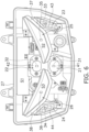
- FIG. 6 is a front view of the light unit 3 with the light blocking member 29A removed.
- FIG. 7 is a front view of the light blocking member 29A.
- the light unit 3 includes light sources 31 and 32 for the headlights 21 and 22, light sources 33 and 34 for the flashers 23 and 24, and light sources 35 and 36 for the position lamps 25 and 26.
- the light sources 31 and 32 for the headlights 21 and 22, the light sources 33 and 34 for the flashers 23 and 24, and the light sources 35 and 36 for the position lamps 25 and 26 are, for example, LEDs.
- the light sources 31 and 32 for the headlights 21 and 22, the light sources 33 and 34 for the flashers 23 and 24, and the light sources 35 and 36 for the position lamps 25 and 26 may be bulbs.
- the number of light sources for the headlights 21 and 22 is not limited to one each, and may be multiple.
- the number of light sources for the flashers 23 and 24 is not limited to one each, and may be multiple.
- the number of light sources for the position lamps 25 and 26 is not limited to one each, and may be multiple.
- the light unit 3 includes inner lenses 41 and 42 for the headlights 21 and 22 and inner lenses 43 and 44 for the flashers 23 and 24.
- the inner lenses 41 and 42 for the headlights 21 and 22 and the inner lenses 43 and 44 for the flashers 23 and 24 are attached to the housing 27.
- the inner lens 41 for the first headlight 21 is disposed in front of the light source 31 for the first headlight 21.
- the inner lens 41 transmits light from the light source 31.
- the inner lens 42 for the second headlight 22 is disposed in front of the light source 32 for the second headlight 22.
- the inner lens 42 transmits light from the light source 32.
- the inner lens 43 for the left flasher 23 is disposed in front of the light source 33 for the left flasher 23.
- the inner lens 43 transmits light from the light source 33.
- the inner lens 44 for the right flasher 24 is disposed in front of the light source 34 for the right flasher 24.
- the inner lens 44 transmit the light from the light sources 34.
- the housing 27 includes a main internal space S1, a left internal space S2, and a right internal space S3.
- the light sources 31 and 32 of the headlights 21 and 22 and the light sources 33 and 34 of the flashers 23 and 24 are arranged in the main internal space S 1.
- the light source 35 for the left position lamp 25 (hereinafter referred to as the left light source) is disposed in the left internal space S2.
- the light source 36 for the right position lamp 26 (hereinafter referred to as the right light source) is disposed in the right internal space S3.
- the light unit 3 includes a left partition member 37 and a right partition member 38.
- the left partition member 37 and the right partition member 38 protrude forward from the housing 27.
- the left partition member 37 and the right partition member 38 may be separated bodies from the housing 27.
- the left partition member 37 and the right partition member 38 may be integral with the housing 27.
- the left partition member 37 partitions the left internal space S2 from the main internal space S 1.
- the left partition member 37 is disposed so as to surround the periphery of the left internal space S2.
- the right partition member 38 partitions the right internal space S3 from the main internal space S1.
- the right partition member 38 is disposed so as to surround the periphery of the right internal space S3.
- the left partition member 37 and the right partition member 38 are each open toward the front.
- the light blocking member 29A is disposed in front of the left partition member 37 and the right partition member 38.
- the light blocking member 29A closes the left partition member 37 and the right partition member 38 from the front. As a result, the light blocking member 29A closes the left internal space S2 and the right internal space S3.
- the light blocking member 29A includes openings 51 and 52 for the headlights 21 and 22 and openings 53 and 54 for the flashers 23 and 24.
- the openings 51 and 52 for the headlights 21 and 22 include a first opening 51 and a second opening 52.
- the first opening 51 and the second opening 52 are arranged side by side in the vertical direction.
- the first opening 51 is disposed in front of the light source 31 for the first headlight 21.
- the second opening 52 is disposed in front of the light source 32 for the second headlight 22.
- the openings 53 and 54 for the flashers 23 and 24 include a left opening 53 and a right opening 54.
- the left opening 53 is disposed leftward of the first opening 51 and the second opening 52.
- the left opening 53 is disposed in front of the light source 33 for the left flasher 23.
- the right opening 54 is disposed rightward of the first opening 51 and the second opening 52.
- the right opening 54 is disposed in front of the light source 34 for the right flasher 24.
- the light blocking member 29A includes a left window 55 and a right window 56.
- the left window 55 and the right window 56 are openings provided in the light blocking member 29A.
- the left window 55 is disposed in front of the left internal space S2.
- the left window 55 is disposed between the left opening 53 and the openings 51 and 52 for the headlights 21 and 22.
- the right window 56 is disposed in front of the right internal space S3.
- the right window 56 is disposed between the right opening 54 and the openings 51 and 52 for the headlights 21 and 22.
- a left inner lens 45 is attached to the left window 55.
- a right inner lens 46 is attached to the right window 56.
- the left inner lens 45 and the right inner lens 46 each transmit light.
- FIG. 8 is a cross-sectional view taken along line VIII-VIII in FIG. 5 .
- the left light source 35 is disposed in the left internal space S2.
- the left light source 35 irradiates light so that the left internal space S2 is filled with the light.
- the left window 55 transmits the light filling the left internal space S2.
- the right light source 36 is disposed in the right internal space S3.
- the right light source 36 emits light so that the right internal space S3 is filled with the light.
- the right window 56 transmits the light filling the right internal space S3.
- a light diffusing material or a light guiding material may be disposed in each of the left internal space S2 and the right internal space S3.
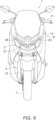
- FIG. 9 is a front view of the straddled vehicle 1 with the headlight 21 and the left and right position lamps 25 and 26 turned on. In FIG. 9 and the subsequent drawings, the light of the headlight 21 and the light of the left and right position lamps 25 and 26 are represented by hatching.
- the shape of the light from the left position lamp 25 and the right position lamp 26 is determined by the shapes of the left window 55 and the right window 56 of the light blocking member 29A described above.
- the shape of the left window 55 of the light blocking member 29A forms a shape of the light that extends upward and laterally outward from the left position lamp 25.
- the shape of the right window 56 of the light blocking member 29A forms a shape of the light that extends upward and laterally outward from the right position lamp 26.
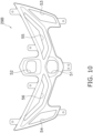
- FIG. 10 is a front view of a light blocking member 29B according to a second example.
- the left window 55 has a shape that is curved downward.
- the right window 56 has a shape symmetrical to the left window 55.
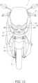
- FIG. 11 is a front view of a straddled vehicle 1 to which the light blocking member 29B according to the second example is attached.
- the shapes of the light emitted by the left position lamp 25 and the right position lamp 26 are determined by the shapes of the left window 55 and the right window 56 of the light blocking member 29B according to the second example described above.
- the shape of the left window 55 of the light blocking member 29B forms a shape of the light that is curved downward from the left position lamp 25.
- the shape of the right window 56 of the light blocking member 29B forms a shape of the light that is curved downward from the right position lamp 26.
- FIG. 12 is a front view of a light blocking member 29C according to a third example.
- the left window 55 includes a first linear shape 61 and a second linear shape 62 that is disposed away from the first linear shape 61.
- the first linear shape 61 extends upward and laterally outward.
- the second linear shape 62 is disposed below the first linear shape 61.
- the second linear shape 62 extends upward and laterally outward.
- the second linear shape 62 is connected to the first linear shape 61 at the outer end of the first linear shape 61.
- the right window 56 has a shape symmetrical to the left window 55.
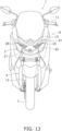
- FIG. 13 is a front view of a straddled vehicle 1 to which the light blocking member 29C according to the third example is attached.
- the shapes of the light from the left position lamp 25 and the right position lamp 26 are determined by the shapes of the left window 55 and the right window 56 of the light blocking member 29C according to the third example described above.
- the shape of the light of the left position lamp 25 is formed by the first linear shape 61 and the second linear shape 62 depending on the shape of the left window 55 of the light blocking member 29C.
- the shape of the light from the right position lamp 26 is formed to be symmetrical to the first linear shape 61 and the second linear shape 62 due to the shape of the right window 56 of the light blocking member 29C.
- FIG. 14 is a front view of a light blocking member 29D according to a fourth example.
- the left window 55 includes a first linear shape 61, a second linear shape 62, and a third linear shape 63.
- the first linear shape 61 extends upward and laterally outward.
- the second linear shape 62 is disposed apart from the first linear shape 61.
- the second linear shape 62 is disposed below the first linear shape 61.
- the second linear shape 62 extends upward and laterally outward.
- the third linear shape 63 is disposed apart from the second linear shape 62.
- the third linear shape 63 is disposed below the second linear shape 62.
- the third linear shape 63 extends upward and laterally outward.
- the right window 56 has a shape symmetrical to the left window 55.
- FIG. 15 is a front view of a straddled vehicle 1 to which a light blocking member 29D according to the fourth example is attached.
- the shapes of the light from the left position lamp 25 and the right position lamp 26 are determined by the shapes of the left window 55 and the right window 56 of the light blocking member 29D according to the fourth example described above.
- the shape of the light from the left position lamp 25 is formed by the first to third linear shapes 61 to 63 that are disposed apart from one another in the vertical direction, depending on the shape of the left window 55 of the light blocking member 29D according to the fourth example.
- the shape of the light from the right position lamp 26 that is symmetrical to the first to third linear shapes 61 to 63 is formed by the shape of the right window 56 of the light blocking member 29D according to the fourth example.
- the third linear shape 63 extends upward and laterally outward.
- the fourth linear shape 64 is disposed away from the third linear shape 63.
- the fourth linear shape 64 is disposed laterally outward of the third linear shape 63.
- the fourth linear shape 64 extends upward and laterally outward.
- the right window 56 has a shape symmetrical to the left window 55.
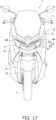
- FIG. 17 is a front view of a straddled vehicle 1 to which the light blocking member 29E according to the fifth example is attached.
- the shapes of the light from the left position lamp 25 and the right position lamp 26 are determined by the shapes of the left window 55 and the right window 56 of the light blocking member 29E according to the fifth example described above.
- the shape of the light from the left position lamp 25 is formed by the first to fourth linear shapes 61 to 64 that are arranged apart from one another in the left-right direction, depending on the shape of the left window 55 of the light blocking member 29E according to the fifth example.
- the shape of the light of the right position lamp 26 is formed to be symmetrical with respect to the first to fourth linear shapes 61 to 64 that are arranged apart from each other in the left-right direction.
- the shape of the light emitted by the position lamps 25 and 26 is determined by the shape of the windows 55 and 56 of the light blocking member 29A attached to the housing 27. Therefore, by changing the shape of the windows 55 to 56 of the light blocking member 29A, the shape of the light emitted by the position lamps 25 and 26 can be easily changed.
- the above-mentioned multiple types of light blocking members 29A to 29E are prepared, and the shape of the light of the position lamps 25 and 26 can be easily changed by selecting one of them.
- the shape of the light emitted by the position lamps 25 and 26 can be easily changed by replacing the light blocking member 29A attached to the straddled vehicle 1 with other types of light blocking members 29B to 29E having windows 55 and 56 with different shapes.
- the straddled vehicle 1 is not limited to a scooter, but may be other types of vehicles such as a sports type, a street type, an off-road type, or a moped.
- the light unit 3 described above is provided on the front cover 13. However, the light unit 3 may be provided at the rear of the straddled vehicle 1.
- the structure of the light unit 3 is not limited to that in the above embodiment and may be modified.
- the arrangement or shape of the headlight 21 may be changed.
- the arrangement or shape of the flashers 23 and 24 may be changed.
- the arrangement or shape of the position lamps 25 and 26 may be changed.
- the shape of the windows 55 and 56 of the light blocking member is not limited to that in the above embodiment and may be changed.
- FIG. 18 is a cross-sectional view of a light unit 3 according to a first modified example.
- FIG. 19 is a schematic diagram of a part of the light unit 3 according to the first modified example.
- a left light source 35A may be disposed on the lower surface of the left partition member 37.
- a left light source 35B may be disposed on the upper surface of the left partition member 37.
- the left light sources 35B and 35A overlap with the light blocking member 29F in the front-rear direction, the light reflected within the left partition member 37 leaks out through the left window 55, thereby forming the shape of the left position lamp 25 as shown in FIG. 19 .
- the right position lamp 26 is similar to the left position lamp 25.
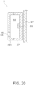
- FIG. 20 is a cross-sectional view of a light unit 3 according to a second modified example.
- FIG. 21 is a schematic diagram of a part of the light unit 3 according to the second modified example.
- the left light source 35 may be disposed on the rear surface of the left partition member 37.
- the left light source 35 may be disposed at a position not facing the left window 55.
- the left light source 35 may be disposed at a position overlapping with the light blocking member 29G in the front-rear direction.
- the right position lamp 26 is similar to the left position lamp 25.
Landscapes
- Engineering & Computer Science (AREA)
- General Engineering & Computer Science (AREA)
- Mechanical Engineering (AREA)
- Physics & Mathematics (AREA)
- Microelectronics & Electronic Packaging (AREA)
- Optics & Photonics (AREA)
- Non-Portable Lighting Devices Or Systems Thereof (AREA)
- Lighting Device Outwards From Vehicle And Optical Signal (AREA)
Abstract
Description
- The present invention relates to a straddled vehicle.
- The straddled vehicle includes a light unit. The light unit includes a position lamp (for example,
JP 2013-112295A - In the above-mentioned straddled vehicle, the shape of the light emitted by the position lamp is determined by the shape of the reflector. Therefore, in order to change the shape of the light emitted by the position lamp, it is necessary to change the shape of the reflector. Since changing the shape of the reflector affects the shape or arrangement of other parts of the light unit, in order to change the shape of the light emitted by the position lamp, it is necessary to change the whole design of the light unit. Therefore, it is not easy to change the shape of the light from the position lamp. An object of the present invention is to provide a straddled vehicle in which the shape of the light from the position lamp can be easily changed.
- A straddled vehicle according to one aspect of the present invention includes a vehicle body and a light unit. The light unit includes a position lamp and is attached to the vehicle body. The light unit includes a housing, a light source, and a light blocking member. The housing includes an internal space. The light source irradiates light so that the internal space is filled with the light. The light blocking member is attached to the housing and closes the internal space. The light blocking member includes a window that transmits the light filling the internal space. The shape of the light emitted by the position lamp is determined by the shape of the window.
- In the straddled vehicle according to the present aspect, the shape of the light from the position lamp is determined by the shape of the window of the light blocking member attached to the housing. Therefore, by changing the shape of the window of the light blocking member, the shape of the light emitted by the position lamp can be easily changed. For example, when manufacturing a straddled vehicle, a number of types of light blocking members with different window shapes can be prepared, and the shape of the light from the position lamp can be easily changed by selecting one of them. Alternatively, even after the manufacture of the straddled vehicle, the shape of the light from the position lamp can be easily changed by replacing the light blocking member attached to the straddled vehicle with another type of light blocking member having a window with a different shape.
- The light blocking member may include an inner lens attached to the window. In this case, the light blocking member is protected by the inner lens. The light unit may further include an outer lens that covers the light blocking member. In this case, the light blocking member is protected by the outer lens.
- The window may have a shape that extends upward and laterally outward. The window may have a shape that curves downward.
- The window may include a first linear shape and a second linear shape. The second linear shape may be disposed apart from the first linear shape. The second linear shape may be connected to the first linear shape at an end of the first linear shape. The second linear shape may be disposed below the first linear shape.
- The window may include a first linear shape, a second linear shape, and a third linear shape. The second linear shape may be disposed apart from the first linear shape. The third linear shape may be disposed apart from the second linear shape. The second linear shape may be disposed below the first linear shape. The third linear shape may be disposed below the second linear shape. The second linear shape may be disposed laterally outward of the first linear shape. The third linear shape may be disposed laterally outward of the second linear shape.
- In the straddled vehicle according to the present aspect, the shape of the light from the position lamp can be easily changed by selectively attaching a light blocking member having a different window shape as described above to the straddled vehicle during or after the manufacture of the straddled vehicle. Furthermore, a plurality of linear lights of the position lamp can be formed by light from a common light source. This reduces the number of light sources, thereby enabling the light unit to be made smaller.
-
-
FIG. 1 is a side view of a straddled vehicle according to an embodiment. -
FIG. 2 is a front view of the straddled vehicle. -
FIG. 3 is a perspective view of a light unit. -
FIG. 4 is a perspective view of the light unit with an outer lens omitted. -
FIG. 5 is a front view of the light unit with the outer lens omitted. -
FIG. 6 is a front view of the light unit with a light blocking member removed. -
FIG. 7 is a front view of the light blocking member according to a first example. -
FIG. 8 is a cross-sectional view taken along line VIII-VIII inFIG. 5 . -
FIG. 9 is a front view of the straddled vehicle to which the light blocking member according to the first example is attached and in which the headlight and the left and right position lamps are turned on. -
FIG. 10 is a front view of a light blocking member according to a second example. -
FIG. 11 is a front view of a straddled vehicle to which the light blocking member according to the second example is attached and in which the headlight and the left and right position lamps are turned on. -
FIG. 12 is a front view of a light blocking member according to a third example. -
FIG. 13 is a front view of a straddled vehicle to which the light blocking member according to the third example is attached and in which the headlight and the left and right position lamps are turned on. -
FIG. 14 is a front view of a light blocking member according to a fourth example. -
FIG. 15 is a front view of a straddled vehicle to which the light blocking member according to the fourth example is attached and in which the headlight and the left and right position lamps are turned on. -
FIG. 16 is a front view of a light blocking member according to a fifth example. -
FIG. 17 is a front view of a straddled vehicle to which the light blocking member according to the fifth example is attached and in which the headlight and the left and right position lamps are turned on. -
FIG. 18 is a cross-sectional view of a light unit according to a first modified example. -
FIG. 19 is a schematic diagram of a part of the light unit according to the first modified example. -
FIG. 20 is a cross-sectional view of a light unit according to a second modified example. -
FIG. 21 is a schematic diagram of a part of the light unit according to the second modified example. - A straddled vehicle according to an embodiment will now be described with reference to the drawings.
FIG. 1 is a side view of a straddledvehicle 1 according to an embodiment.FIG. 2 is a front view of the straddledvehicle 1. In the present embodiment, the straddledvehicle 1 is a scooter. As shown inFIGS. 1 and2 , a straddledvehicle 1 includes avehicle body 2 and alight unit 3. Thevehicle body 2 includes asteering device 4, aseat 5, a power unit 6, afront wheel 7, arear wheel 8, and avehicle body cover 9. In the following description, the left and right directions refer to the left and right directions as seen by a rider seated on theseat 5. - The
steering device 4 includes ahandlebar 11 and afront fork 12. Thehandlebar 11 is connected to thefront fork 12. Thehandlebar 11 is operable to the left and right by the rider. Thefront fork 12 rotatably supports thefront wheel 7. Theseat 5 is disposed behind thesteering device 4. The power unit 6 is disposed below theseat 5. The power unit 6 includes, for example, an internal combustion engine and a transmission. Alternatively, the power unit 6 may include an electric motor. Therear wheel 8 is rotatably supported by the power unit 6. Alternatively, therear wheel 8 may be rotatably supported by a swing arm. - The
vehicle body cover 9 includes afront cover 13. Thefront cover 13 is disposed in front of thesteering device 4. Thelight unit 3 is attached to thevehicle body 2. In detail, thelight unit 3 is attached to thefront cover 13. Thelight unit 3 includesheadlights flashers position lamps headlights flashers position lamps light unit 3. - The
headlights first headlight 21 and asecond headlight 22. Thefirst headlight 21 and thesecond headlight 22 are arranged side by side in the vertical direction. For example, thefirst headlight 21 is a high beam light and thesecond headlight 22 is a low beam light. Alternatively, thefirst headlight 21 may be a low beam light and thesecond headlight 22 may be a high beam light. - The
flashers left flasher 23 and aright flasher 24. Theleft flasher 23 is disposed leftward of theheadlights right flasher 24 is disposed rightward of theheadlights left flasher 23 and theright flasher 24 each extend in the vertical direction. - The
position lamps left position lamp 25 and aright position lamp 26. Theleft position lamp 25 is disposed leftward of theheadlights left position lamp 25 is disposed between theheadlights left flasher 23. Theright position lamp 26 is disposed rightward of theheadlights right position lamp 26 is disposed between theheadlights right flasher 24. Theleft position lamp 25 and theright position lamp 26 each have a shape that extends upward and laterally outward. -
FIG. 3 is a perspective view of thelight unit 3. As shown inFIG. 3 , thelight unit 3 includes ahousing 27 and anouter lens 28. Theouter lens 28 is made of a transparent material. Theouter lens 28 may be colored. Theouter lens 28 is attached to thehousing 27. Theouter lens 28 covers thehousing 27 from the front. -
FIG. 4 is a perspective view of thelight unit 3 with theouter lens 28 omitted.FIG. 5 is a front view of thelight unit 3 with theouter lens 28 omitted. As shown inFIGS. 4 and5 , thelight unit 3 includes alight blocking member 29A. Thelight blocking member 29A has a light blocking property. For example, thelight blocking member 29A is made of a material such as resin having a light blocking property. Alternatively, thelight blocking member 29A may be coated with a light blocking paint. Thelight blocking member 29A is a separated body from thehousing 27. Thelight blocking member 29A is disposed in front of thehousing 27. Thelight blocking member 29A is attached to thehousing 27. Theouter lens 28 described above covers thelight blocking member 29A from the front. -
FIG. 6 is a front view of thelight unit 3 with thelight blocking member 29A removed.FIG. 7 is a front view of thelight blocking member 29A. As shown inFIGS. 5 and6 , thelight unit 3 includeslight sources 31 and 32 for theheadlights light sources flashers light sources position lamps light sources 31 and 32 for theheadlights light sources flashers light sources position lamps light sources 31 and 32 for theheadlights light sources flashers light sources position lamps - The number of light sources for the
headlights flashers position lamps - The
light unit 3 includesinner lenses 41 and 42 for theheadlights inner lenses flashers inner lenses 41 and 42 for theheadlights inner lenses flashers housing 27. - The
inner lens 41 for thefirst headlight 21 is disposed in front of thelight source 31 for thefirst headlight 21. Theinner lens 41 transmits light from thelight source 31. The inner lens 42 for thesecond headlight 22 is disposed in front of the light source 32 for thesecond headlight 22. The inner lens 42 transmits light from the light source 32. - The
inner lens 43 for theleft flasher 23 is disposed in front of thelight source 33 for theleft flasher 23. Theinner lens 43 transmits light from thelight source 33. Theinner lens 44 for theright flasher 24 is disposed in front of thelight source 34 for theright flasher 24. Theinner lens 44 transmit the light from thelight sources 34. - As shown in
FIG. 6 , thehousing 27 includes a main internal space S1, a left internal space S2, and a right internal space S3. Thelight sources 31 and 32 of theheadlights light sources flashers internal space S 1. Thelight source 35 for the left position lamp 25 (hereinafter referred to as the left light source) is disposed in the left internal space S2. Thelight source 36 for the right position lamp 26 (hereinafter referred to as the right light source) is disposed in the right internal space S3. - The
light unit 3 includes aleft partition member 37 and aright partition member 38. Theleft partition member 37 and theright partition member 38 protrude forward from thehousing 27. Theleft partition member 37 and theright partition member 38 may be separated bodies from thehousing 27. Alternatively, theleft partition member 37 and theright partition member 38 may be integral with thehousing 27. Theleft partition member 37 partitions the left internal space S2 from the maininternal space S 1. Theleft partition member 37 is disposed so as to surround the periphery of the left internal space S2. Theright partition member 38 partitions the right internal space S3 from the main internal space S1. Theright partition member 38 is disposed so as to surround the periphery of the right internal space S3. - The
left partition member 37 and theright partition member 38 are each open toward the front. Thelight blocking member 29A is disposed in front of theleft partition member 37 and theright partition member 38. Thelight blocking member 29A closes theleft partition member 37 and theright partition member 38 from the front. As a result, thelight blocking member 29A closes the left internal space S2 and the right internal space S3. - As shown in
FIG. 7 , thelight blocking member 29A includesopenings headlights openings flashers openings headlights first opening 51 and asecond opening 52. Thefirst opening 51 and thesecond opening 52 are arranged side by side in the vertical direction. Thefirst opening 51 is disposed in front of thelight source 31 for thefirst headlight 21. Thesecond opening 52 is disposed in front of the light source 32 for thesecond headlight 22. - The
openings flashers left opening 53 and aright opening 54. Theleft opening 53 is disposed leftward of thefirst opening 51 and thesecond opening 52. Theleft opening 53 is disposed in front of thelight source 33 for theleft flasher 23. Theright opening 54 is disposed rightward of thefirst opening 51 and thesecond opening 52. Theright opening 54 is disposed in front of thelight source 34 for theright flasher 24. - The
light blocking member 29A includes aleft window 55 and aright window 56. Theleft window 55 and theright window 56 are openings provided in thelight blocking member 29A. Theleft window 55 is disposed in front of the left internal space S2. Theleft window 55 is disposed between theleft opening 53 and theopenings headlights right window 56 is disposed in front of the right internal space S3. Theright window 56 is disposed between theright opening 54 and theopenings headlights inner lens 45 is attached to theleft window 55. A rightinner lens 46 is attached to theright window 56. The leftinner lens 45 and the rightinner lens 46 each transmit light. -
FIG. 8 is a cross-sectional view taken along line VIII-VIII inFIG. 5 . As shown inFIG. 8 , the leftlight source 35 is disposed in the left internal space S2. The leftlight source 35 irradiates light so that the left internal space S2 is filled with the light. Theleft window 55 transmits the light filling the left internal space S2. Similarly, the rightlight source 36 is disposed in the right internal space S3. The rightlight source 36 emits light so that the right internal space S3 is filled with the light. Theright window 56 transmits the light filling the right internal space S3. A light diffusing material or a light guiding material may be disposed in each of the left internal space S2 and the right internal space S3. - The
left window 55 and theright window 56 each have a shape that extends upward and laterally outward. The shapes of the light from theleft position lamp 25 and theright position lamp 26 are determined by the shapes of theleft window 55 and theright window 56.FIG. 9 is a front view of the straddledvehicle 1 with theheadlight 21 and the left andright position lamps FIG. 9 and the subsequent drawings, the light of theheadlight 21 and the light of the left andright position lamps - As shown in
FIG. 9 , the shape of the light from theleft position lamp 25 and theright position lamp 26 is determined by the shapes of theleft window 55 and theright window 56 of thelight blocking member 29A described above. The shape of theleft window 55 of thelight blocking member 29A forms a shape of the light that extends upward and laterally outward from theleft position lamp 25. The shape of theright window 56 of thelight blocking member 29A forms a shape of the light that extends upward and laterally outward from theright position lamp 26. - The
light blocking member 29A described above is a first example of thelight blocking member 29A according to the present embodiment.FIG. 10 is a front view of alight blocking member 29B according to a second example. As shown inFIG. 10 , in thelight blocking member 29B according to the second example, theleft window 55 has a shape that is curved downward. Theright window 56 has a shape symmetrical to theleft window 55. -
FIG. 11 is a front view of a straddledvehicle 1 to which thelight blocking member 29B according to the second example is attached. As shown inFIG. 11 , the shapes of the light emitted by theleft position lamp 25 and theright position lamp 26 are determined by the shapes of theleft window 55 and theright window 56 of thelight blocking member 29B according to the second example described above. The shape of theleft window 55 of thelight blocking member 29B forms a shape of the light that is curved downward from theleft position lamp 25. The shape of theright window 56 of thelight blocking member 29B forms a shape of the light that is curved downward from theright position lamp 26. -
FIG. 12 is a front view of alight blocking member 29C according to a third example. As shown inFIG. 12 , in thelight blocking member 29C according to the third example, theleft window 55 includes a firstlinear shape 61 and a secondlinear shape 62 that is disposed away from the firstlinear shape 61. The firstlinear shape 61 extends upward and laterally outward. The secondlinear shape 62 is disposed below the firstlinear shape 61. The secondlinear shape 62 extends upward and laterally outward. The secondlinear shape 62 is connected to the firstlinear shape 61 at the outer end of the firstlinear shape 61. Theright window 56 has a shape symmetrical to theleft window 55. -
FIG. 13 is a front view of a straddledvehicle 1 to which thelight blocking member 29C according to the third example is attached. As shown inFIG. 13 , the shapes of the light from theleft position lamp 25 and theright position lamp 26 are determined by the shapes of theleft window 55 and theright window 56 of thelight blocking member 29C according to the third example described above. The shape of the light of theleft position lamp 25 is formed by the firstlinear shape 61 and the secondlinear shape 62 depending on the shape of theleft window 55 of thelight blocking member 29C. The shape of the light from theright position lamp 26 is formed to be symmetrical to the firstlinear shape 61 and the secondlinear shape 62 due to the shape of theright window 56 of thelight blocking member 29C. -
FIG. 14 is a front view of alight blocking member 29D according to a fourth example. As shown inFIG. 14 , in thelight blocking member 29D according to the fourth example, theleft window 55 includes a firstlinear shape 61, a secondlinear shape 62, and a thirdlinear shape 63. The firstlinear shape 61 extends upward and laterally outward. The secondlinear shape 62 is disposed apart from the firstlinear shape 61. The secondlinear shape 62 is disposed below the firstlinear shape 61. The secondlinear shape 62 extends upward and laterally outward. The thirdlinear shape 63 is disposed apart from the secondlinear shape 62. The thirdlinear shape 63 is disposed below the secondlinear shape 62. The thirdlinear shape 63 extends upward and laterally outward. Theright window 56 has a shape symmetrical to theleft window 55. -
FIG. 15 is a front view of a straddledvehicle 1 to which alight blocking member 29D according to the fourth example is attached. As shown inFIG. 15 , the shapes of the light from theleft position lamp 25 and theright position lamp 26 are determined by the shapes of theleft window 55 and theright window 56 of thelight blocking member 29D according to the fourth example described above. The shape of the light from theleft position lamp 25 is formed by the first to thirdlinear shapes 61 to 63 that are disposed apart from one another in the vertical direction, depending on the shape of theleft window 55 of thelight blocking member 29D according to the fourth example. The shape of the light from theright position lamp 26 that is symmetrical to the first to thirdlinear shapes 61 to 63 is formed by the shape of theright window 56 of thelight blocking member 29D according to the fourth example. -
FIG. 16 is a front view of alight blocking member 29E according to a fifth example. As shown inFIG. 16 , in thelight blocking member 29E according to the fifth example, theleft window 55 includes a firstlinear shape 61, a secondlinear shape 62, a thirdlinear shape 63, and a fourthlinear shape 64. The firstlinear shape 61 extends upward and laterally outward. The secondlinear shape 62 is disposed apart from the firstlinear shape 61. The secondlinear shape 62 is disposed laterally outward of the firstlinear shape 61. The secondlinear shape 62 extends upward and laterally outward. The thirdlinear shape 63 is disposed away from the secondlinear shape 62. The thirdlinear shape 63 is disposed laterally outward of the secondlinear shape 62. The thirdlinear shape 63 extends upward and laterally outward. The fourthlinear shape 64 is disposed away from the thirdlinear shape 63. The fourthlinear shape 64 is disposed laterally outward of the thirdlinear shape 63. The fourthlinear shape 64 extends upward and laterally outward. Theright window 56 has a shape symmetrical to theleft window 55. -
FIG. 17 is a front view of a straddledvehicle 1 to which thelight blocking member 29E according to the fifth example is attached. As shown inFIG. 17 , the shapes of the light from theleft position lamp 25 and theright position lamp 26 are determined by the shapes of theleft window 55 and theright window 56 of thelight blocking member 29E according to the fifth example described above. The shape of the light from theleft position lamp 25 is formed by the first to fourthlinear shapes 61 to 64 that are arranged apart from one another in the left-right direction, depending on the shape of theleft window 55 of thelight blocking member 29E according to the fifth example. Due to the shape of theright window 56 of thelight blocking member 29E according to the fifth example, the shape of the light of theright position lamp 26 is formed to be symmetrical with respect to the first to fourthlinear shapes 61 to 64 that are arranged apart from each other in the left-right direction. - In the straddled
vehicle 1 according to the present embodiment described above, the shape of the light emitted by theposition lamps windows light blocking member 29A attached to thehousing 27. Therefore, by changing the shape of thewindows 55 to 56 of thelight blocking member 29A, the shape of the light emitted by theposition lamps - For example, when manufacturing the straddled
vehicle 1, the above-mentioned multiple types oflight blocking members 29A to 29E are prepared, and the shape of the light of theposition lamps vehicle 1, the shape of the light emitted by theposition lamps light blocking member 29A attached to the straddledvehicle 1 with other types oflight blocking members 29B to29E having windows - Although one embodiment of the present invention has been described above, the present invention is not limited to the above embodiment, and various modifications are possible without departing from the gist of the invention.
- The straddled
vehicle 1 is not limited to a scooter, but may be other types of vehicles such as a sports type, a street type, an off-road type, or a moped. Thelight unit 3 described above is provided on thefront cover 13. However, thelight unit 3 may be provided at the rear of the straddledvehicle 1. - The structure of the
light unit 3 is not limited to that in the above embodiment and may be modified. For example, the arrangement or shape of theheadlight 21 may be changed. The arrangement or shape of theflashers position lamps windows -
FIG. 18 is a cross-sectional view of alight unit 3 according to a first modified example.FIG. 19 is a schematic diagram of a part of thelight unit 3 according to the first modified example. As shown inFIGS. 18 and19 , a leftlight source 35A may be disposed on the lower surface of theleft partition member 37. A leftlight source 35B may be disposed on the upper surface of theleft partition member 37. In this case, even if the leftlight sources light blocking member 29F in the front-rear direction, the light reflected within theleft partition member 37 leaks out through theleft window 55, thereby forming the shape of theleft position lamp 25 as shown inFIG. 19 . Although not shown in the figure, theright position lamp 26 is similar to theleft position lamp 25. -
FIG. 20 is a cross-sectional view of alight unit 3 according to a second modified example.FIG. 21 is a schematic diagram of a part of thelight unit 3 according to the second modified example. As shown inFIGS. 20 and21 , the leftlight source 35 may be disposed on the rear surface of theleft partition member 37. The leftlight source 35 may be disposed at a position not facing theleft window 55. The leftlight source 35 may be disposed at a position overlapping with thelight blocking member 29G in the front-rear direction. In this case, even if the leftlight source 35 overlaps with thelight blocking member 29G in the front-rear direction, the light reflected within theleft partition member 37 leaks out through theleft window 55, thereby forming the shape of theleft position lamp 25 as shown inFIG. 21 . Although not shown in the figure, theright position lamp 26 is similar to theleft position lamp 25. - 2: Vehicle body, 3: Light unit, 25: Left position lamp, 26: Right position lamp, 27: Housing, 28: Outer lens, 29A to 29G: Light blocking member, 35: Left light source, 36: Right light source, 45: Left inner lens, 46: Right inner lens, 55: Left window, 56: Right window, 61: First linear shape, 62: Second linear shape, 63: Third linear shape, S2: Left internal space, S3: Right internal space
Claims (11)
- A straddled vehicle (1) comprising:a vehicle body (2); anda light unit (3) including a position lamp (25, 26) and attached to the vehicle body (2), whereinthe light unit (3) includesa housing (27) including an internal space (S2, S3),a light source (35, 36) configured to irradiate light so that the internal space (S2, S3) is filled with the light, anda light blocking member (29A-29G) attached to the housing and closing the internal space (S2, S3),the light blocking member (29A-29G) includes a window configured to transmit the light filling the internal space (S2, S3), anda shape of the light from the position lamp is formed by a shape of the window (55, 56).
- The straddled vehicle according to claim 1, wherein
the light blocking member (29A-29G) includes an inner lens (41, 42, 43, 44, 45, 46) attached to the window (55, 56). - The straddled vehicle according to claim 2, wherein
the light unit (3) further includes an outer lens (28) covering the light blocking member (29A). - The straddled vehicle according to any one of claims 1 to 3, wherein
the window (55, 56) has a shape extending upward and laterally outward. - The straddled vehicle according to any one of claims 1 to 4, wherein
the window (55, 56) has a shape curved downward. - The saddle-type straddled vehicle according to any one of claims 1 to 4, wherein
the window (55, 56) includesa first linear shape (61), anda second linear shape (62) disposed apart from the first linear shape (61). - The straddled vehicle according to claim 6, wherein
the second linear shape (62) is connected to the first linear shape (61) at an end of the first linear shape (61). - The straddled vehicle according to claim 6 or 7, wherein
the second linear shape (62) is disposed below the first linear shape (61). - The straddled vehicle according to any one of claims 1 to 4, wherein
the window (55, 56) includesa first linear shape (61),a second linear shape (62) disposed apart from the first linear shape 6(1), anda third linear shape (63) disposed apart from the second linear shape (62). - The straddled vehicle according to claim 9, whereinthe second linear shape (62) is disposed below the first linear shape (61), andthe third linear shape (63) is disposed below the second linear shape (62).
- The straddled vehicle according to claim 9, whereinthe second linear shape (62) is disposed laterally outward of the first linear shape (61), andthe third linear shape (63) is disposed laterally outward of the second linear shape (62).
Applications Claiming Priority (1)
| Application Number | Priority Date | Filing Date | Title |
|---|---|---|---|
| JP2023207377A JP2025091858A (en) | 2023-12-08 | 2023-12-08 | Saddle-type vehicle |
Publications (1)
| Publication Number | Publication Date |
|---|---|
| EP4566926A1 true EP4566926A1 (en) | 2025-06-11 |
Family
ID=93291888
Family Applications (1)
| Application Number | Title | Priority Date | Filing Date |
|---|---|---|---|
| EP24209219.5A Pending EP4566926A1 (en) | 2023-12-08 | 2024-10-28 | Straddled vehicle position light |
Country Status (4)
| Country | Link |
|---|---|
| EP (1) | EP4566926A1 (en) |
| JP (1) | JP2025091858A (en) |
| CO (1) | CO2024016121A1 (en) |
| TW (1) | TW202523545A (en) |
Citations (5)
| Publication number | Priority date | Publication date | Assignee | Title |
|---|---|---|---|---|
| CN201382348Y (en) * | 2009-03-25 | 2010-01-13 | 光阳工业股份有限公司 | Position lamp device for vehicle |
| JP2013112295A (en) | 2011-11-30 | 2013-06-10 | Yamaha Motor Co Ltd | Straddle type vehicle |
| EP3067235A2 (en) * | 2015-03-11 | 2016-09-14 | Honda Motor Co., Ltd. | Vehicle lighting device |
| JP2017019408A (en) * | 2015-07-10 | 2017-01-26 | ヤマハ発動機株式会社 | Saddle-riding type vehicle |
| JP2021030797A (en) * | 2019-08-21 | 2021-03-01 | ヤマハ発動機株式会社 | Scooter type vehicle |
-
2023
- 2023-12-08 JP JP2023207377A patent/JP2025091858A/en active Pending
-
2024
- 2024-10-28 EP EP24209219.5A patent/EP4566926A1/en active Pending
- 2024-11-27 CO CONC2024/0016121A patent/CO2024016121A1/en unknown
- 2024-11-29 TW TW113146433A patent/TW202523545A/en unknown
Patent Citations (5)
| Publication number | Priority date | Publication date | Assignee | Title |
|---|---|---|---|---|
| CN201382348Y (en) * | 2009-03-25 | 2010-01-13 | 光阳工业股份有限公司 | Position lamp device for vehicle |
| JP2013112295A (en) | 2011-11-30 | 2013-06-10 | Yamaha Motor Co Ltd | Straddle type vehicle |
| EP3067235A2 (en) * | 2015-03-11 | 2016-09-14 | Honda Motor Co., Ltd. | Vehicle lighting device |
| JP2017019408A (en) * | 2015-07-10 | 2017-01-26 | ヤマハ発動機株式会社 | Saddle-riding type vehicle |
| JP2021030797A (en) * | 2019-08-21 | 2021-03-01 | ヤマハ発動機株式会社 | Scooter type vehicle |
Also Published As
| Publication number | Publication date |
|---|---|
| CO2024016121A1 (en) | 2025-11-28 |
| TW202523545A (en) | 2025-06-16 |
| JP2025091858A (en) | 2025-06-19 |
Similar Documents
| Publication | Publication Date | Title |
|---|---|---|
| CN101788123B (en) | Position light and lighting apparatus for motorcycle | |
| EP2500638B1 (en) | Headlamp device | |
| EP1908629B1 (en) | Headlight device and vehicle | |
| JP6290841B2 (en) | Vehicle lighting | |
| JP6490728B2 (en) | Headlight structure of saddle-ride type vehicle | |
| JP5301295B2 (en) | Vehicle taillight device | |
| JP6057772B2 (en) | Light fixture | |
| EP3689722B1 (en) | Combination light | |
| US8262267B2 (en) | Lamp device-integrated rearview mirror | |
| JP6192238B2 (en) | Motorcycle | |
| JP5624200B2 (en) | Vehicle headlamp device | |
| JP2025091858A (en) | Saddle-type vehicle | |
| EP2017167B1 (en) | Vehicle | |
| EP3885193B1 (en) | Straddled vehicle | |
| CN113799896B (en) | Scooter type locomotive | |
| BR102024025089A2 (en) | VEHICLE TO ASSEMBLE | |
| CN216556943U (en) | Lighting device for saddle-ride type vehicle | |
| US20200231238A1 (en) | Position light-integrated blinker apparatus | |
| TWI827070B (en) | Headlamp unit and leaning vehicle | |
| CN102192461A (en) | Headlamp device | |
| JP2024085545A (en) | head lamp | |
| JP6010079B2 (en) | Vehicle headlamp device | |
| JP6579632B2 (en) | Rear combination lamp for saddle-ride type vehicles | |
| CN119705684A (en) | Vehicle body rear structure | |
| JP2012101573A (en) | Head lamp device of motorcycle |
Legal Events
| Date | Code | Title | Description |
|---|---|---|---|
| PUAI | Public reference made under article 153(3) epc to a published international application that has entered the european phase |
Free format text: ORIGINAL CODE: 0009012 |
|
| STAA | Information on the status of an ep patent application or granted ep patent |
Free format text: STATUS: REQUEST FOR EXAMINATION WAS MADE |
|
| 17P | Request for examination filed |
Effective date: 20241028 |
|
| AK | Designated contracting states |
Kind code of ref document: A1 Designated state(s): AL AT BE BG CH CY CZ DE DK EE ES FI FR GB GR HR HU IE IS IT LI LT LU LV MC ME MK MT NL NO PL PT RO RS SE SI SK SM TR |
|
| P01 | Opt-out of the competence of the unified patent court (upc) registered |
Free format text: CASE NUMBER: UPC_APP_0525_4566926/2025 Effective date: 20250717 |
|
| STAA | Information on the status of an ep patent application or granted ep patent |
Free format text: STATUS: EXAMINATION IS IN PROGRESS |
|
| 17Q | First examination report despatched |
Effective date: 20250929 |