EP4566920A1 - Dump truck - Google Patents
Dump truck Download PDFInfo
- Publication number
- EP4566920A1 EP4566920A1 EP23871611.2A EP23871611A EP4566920A1 EP 4566920 A1 EP4566920 A1 EP 4566920A1 EP 23871611 A EP23871611 A EP 23871611A EP 4566920 A1 EP4566920 A1 EP 4566920A1
- Authority
- EP
- European Patent Office
- Prior art keywords
- frame
- cab
- vehicle body
- body frame
- reinforcement member
- Prior art date
- Legal status (The legal status is an assumption and is not a legal conclusion. Google has not performed a legal analysis and makes no representation as to the accuracy of the status listed.)
- Pending
Links
Images


Classifications
-
- B—PERFORMING OPERATIONS; TRANSPORTING
- B62—LAND VEHICLES FOR TRAVELLING OTHERWISE THAN ON RAILS
- B62D—MOTOR VEHICLES; TRAILERS
- B62D21/00—Understructures, i.e. chassis frame on which a vehicle body may be mounted
- B62D21/18—Understructures, i.e. chassis frame on which a vehicle body may be mounted characterised by the vehicle type and not provided for in groups B62D21/02 - B62D21/17
- B62D21/186—Understructures, i.e. chassis frame on which a vehicle body may be mounted characterised by the vehicle type and not provided for in groups B62D21/02 - B62D21/17 for building site vehicles or multi-purpose tractors
-
- B—PERFORMING OPERATIONS; TRANSPORTING
- B60—VEHICLES IN GENERAL
- B60P—VEHICLES ADAPTED FOR LOAD TRANSPORTATION OR TO TRANSPORT, TO CARRY, OR TO COMPRISE SPECIAL LOADS OR OBJECTS
- B60P1/00—Vehicles predominantly for transporting loads and modified to facilitate loading, consolidating the load, or unloading
- B60P1/04—Vehicles predominantly for transporting loads and modified to facilitate loading, consolidating the load, or unloading with a tipping movement of load-transporting element
-
- B—PERFORMING OPERATIONS; TRANSPORTING
- B60—VEHICLES IN GENERAL
- B60P—VEHICLES ADAPTED FOR LOAD TRANSPORTATION OR TO TRANSPORT, TO CARRY, OR TO COMPRISE SPECIAL LOADS OR OBJECTS
- B60P1/00—Vehicles predominantly for transporting loads and modified to facilitate loading, consolidating the load, or unloading
- B60P1/04—Vehicles predominantly for transporting loads and modified to facilitate loading, consolidating the load, or unloading with a tipping movement of load-transporting element
- B60P1/28—Tipping body constructions
-
- B—PERFORMING OPERATIONS; TRANSPORTING
- B62—LAND VEHICLES FOR TRAVELLING OTHERWISE THAN ON RAILS
- B62D—MOTOR VEHICLES; TRAILERS
- B62D33/00—Superstructures for load-carrying vehicles
- B62D33/06—Drivers' cabs
- B62D33/0604—Cabs insulated against vibrations or noise, e.g. with elastic suspension
-
- B—PERFORMING OPERATIONS; TRANSPORTING
- B62—LAND VEHICLES FOR TRAVELLING OTHERWISE THAN ON RAILS
- B62D—MOTOR VEHICLES; TRAILERS
- B62D33/00—Superstructures for load-carrying vehicles
- B62D33/06—Drivers' cabs
- B62D33/0617—Drivers' cabs for tractors or off-the-road vehicles
-
- B—PERFORMING OPERATIONS; TRANSPORTING
- B62—LAND VEHICLES FOR TRAVELLING OTHERWISE THAN ON RAILS
- B62D—MOTOR VEHICLES; TRAILERS
- B62D33/00—Superstructures for load-carrying vehicles
- B62D33/06—Drivers' cabs
- B62D33/063—Drivers' cabs movable from one position into at least one other position, e.g. tiltable, pivotable about a vertical axis, displaceable from one side of the vehicle to the other
- B62D33/067—Drivers' cabs movable from one position into at least one other position, e.g. tiltable, pivotable about a vertical axis, displaceable from one side of the vehicle to the other tiltable
Definitions
- This disclosure relates to dump trucks that are suitably used for transporting crushed stone and the like mined from, for example, mines.
- a dump truck for transporting crushed stone and the like mined from mines comprises a vehicle body frame to which wheels are attached, a vessel tiltably provided relative to the vehicle body frame, and a cab positioned at the front side of the vessel and provided on the vehicle body frame to define an operating room.
- the rear side part of the cab is supported by a cab support part provided on the vehicle body frame, and the front side part of the cab is supported by a front support member arranged at the front side of the vehicle body frame.
- Patent Document 1 a dump truck is disclosed (Patent Document 1) in which a reinforcement member is provided between the upper part of the front support member (building) and the vehicle body frame in an inclined state in the vertical direction (vehicle height direction) to enhance the strength of the front support member.
- Patent Document 1 Japanese Patent Laid-Open No. 2019-43481 A
- the purpose of the present invention is to provide a dump truck that can enhance the support strength of the cab without increasing the weight of the vehicle body.
- the dump truck of the present invention includes a vehicle body frame to which wheels are attached and which extends in the longitudinal direction, a vessel that is tiltably mounted on the vehicle body frame for loading transported materials, and a cab located at the front side of the vessel, which is provided on the vehicle body frame to define the operating room.
- the vehicle body frame is provided with a cab support part supporting the rear side part of the cab, a front support member arranged between the vehicle body frame and the cab to support the front side part of the cab, and a reinforcing member connecting the front support member and the cab support part.
- a spherical bearing is provided at at least one of the connection points between the cab support and the reinforcement member, and between the front support member and the reinforcement member.
- the reinforcing member connecting the cab support part supporting the rear side part of the cab and the front support member supporting the front side part of the cab can reduce the load acting on the front support member during travel. Moreover, even if the vehicle body frame undergoes torsional deformation due to the dump truck traveling on uneven ground, the spherical bearing provided at least at one of the connection parts between the cab support part and the reinforcing member, and between the front support member and the reinforcing member, can absorb the torsional deformation of the vehicle body frame.
- the traveling direction of the dump truck is described as the longitudinal direction, and the direction orthogonal to the traveling direction is described as the lateral direction.
- the dump truck 1 comprises a self-propelled vehicle body 2 equipped with left and right front wheels 3 and left and right rear wheels 4, and a vessel 5, described later, tiltably mounted on the vehicle body 2.
- the dump truck 1 transports materials such as crushed stone excavated from the mine by loading them onto the vessel 5.
- the vehicle body 2 of the dump truck 1 is configured to include a building 7, a deck 8, a cab 9, a vehicle body frame 14, and the like, which will be described later.
- the left and right front wheels 3 are rotatably provided at the front side of the vehicle body 2, constituting steering wheels.
- the front wheels 3 are supported by the vehicle body frame 14 via a front wheel suspension (not shown), and vibrations transmitted from the front wheels 3 to the vehicle body 2 are mitigated.
- the left and right rear wheels 4 are rotatably provided at the rear side of the vehicle body 2 and are rotationally driven by a travel device (not shown) equipped with an electric motor.
- the travel device of the rear wheels 4 is supported by the vehicle body frame 14 via a rear wheel suspension (not shown), and vibrations transmitted from the rear wheels 4 to the vehicle body 2 are mitigated.
- the vessel 5 is tiltably (undulatively) mounted on the vehicle body frame 14.
- the vessel 5 is formed as a large bottomed container for loading a large amount of minerals and the like excavated by, for example, a hydraulic excavator (not shown) .
- the rear bottom part of the vessel 5 is tiltably connected via a connecting pin 5B to left and right rear end brackets 24, which will be described later, provided on the vehicle body frame 14.
- an eave part 5A extending horizontally forward from the upper part is integrally provided.
- the eave part 5A of the vessel 5 extends to the front end side of the deck 8 while covering the cab 9 from above.
- the hoist cylinder 6 is provided in pairs in the lateral direction between the vehicle body frame 14 and the vessel 5 (only the left side is shown) .
- the hoist cylinder 6 is composed of, for example, a hydraulic cylinder and tilts the front side of the vessel 5 up and down relative to the vehicle body frame 14 .
- One end side (lower end side) of the hoist cylinder 6 is pivotally attached to a cylinder support shaft 26, which will be described later, and the other end side (upper end side) of the hoist cylinder 6 is pivotally attached to the lower surface side of the vessel 5.
- the front side (eave part 5A side) of the vessel 5 rotates (moves up and down) in the vertical direction with the connecting pin 5B as a fulcrum.
- the vessel 5 tilts to a dumping position where the front side is lifted upward, allowing the discharge of the transported materials loaded on the vessel 5.
- the building 7 is provided at the front side of the vehicle body 2.
- the building 7 is formed in a rectangular frame shape enclosed by left and right side plates and a top plate, defining a machine room for accommodating mounted equipment such as an engine, a generator, and a hydraulic pump (all not shown).
- the deck 8 is positioned in front of the vessel 5 and is provided on the left support column 22, right support column 23, and the upper side of the building 7 of the vehicle body frame 14.
- the deck 8 is formed in an elongated rectangular flat plate shape in the lateral direction and is supported from below by an upper cross beam 28 and the building 7, which will be described later.
- the deck 8 is arranged above the left and right front wheels 3 and extends in the horizontal direction, with the cab 9, control cabinet 10, and the like mounted on the deck 8.
- the upper surface of the deck 8 serves as a flat passage surface for operators and the like to pass through, and the outer periphery of the deck 8 is surrounded by multiple handrails 8A.
- the cab 9 is positioned at the front side of the vessel 5 and is provided on the vehicle body frame 14, covered from above by the eave part 5A.
- the cab 9 consists of a box body enclosed by a front face, rear face, left and right side faces, top face, and bottom face, defining an operating room for the operator of the dump truck 1 to get on and off.
- the rear side part 9A of the cab 9 is supported from below by the cab support part 28E of the upper cross beam 28, and the front side part 9B of the cab 9 is supported from below by a front support member 30, which will be described later.
- the radiator 11 is provided at the front end side of the vehicle body frame 14.
- the radiator 11 is arranged at the front side of the building 7 and cools the engine coolant and the like of an engine (not shown) housed in the machine room defined by the building 7.
- fenders 12 protruding in the lateral direction from the left and right side plates of the building 7 are provided.
- Each of these left and right fenders 12 is equipped with an air cleaner 13.
- the air cleaner 13 captures dust contained in the outside air at work sites such as mines and supplies clean air (intake air) to the engine.
- the vehicle body frame 14 serves as the base of the vehicle body 2 and constitutes a robust support structure. As shown in Fig. 3 , the vehicle body frame 14 is configured to include a main frame 15 extending in the longitudinal direction and a front bumper 27 integrally fixed to the front side of the main frame 15.
- the main frame 15 is composed of a left frame 16, a right frame 17, a front frame 18, a rear frame 19, an upper plate 20, a lower plate 21, a left support column 22, a right support column 23, an upper cross beam 28, and the like.
- the left frame 16 is positioned on the left side of the vehicle body frame 14 and extends in the longitudinal direction.
- the left frame 16 is composed of left and right side plates 16A facing each other in the lateral direction, an upper plate 20 closing the upper ends of the side plates 16A, and a lower plate 21 connecting the lower ends of the side plates 16A.
- the right frame 17 is positioned on the right side of the vehicle body frame 14 and extends in the longitudinal direction.
- the right frame 17 is composed of left and right side plates 17A facing each other in the lateral direction, an upper plate 20 closing the upper ends of the side plates 17A, and a lower plate 21 connecting the lower ends of the side plates 17A.
- the front frame 18 connects between the front end of the left frame 16 and the front end of the right frame 17.
- the front frame 18 is composed of a front plate 18A and a rear plate (not shown) facing each other in the longitudinal direction, an upper plate 20 closing the upper ends of the front plate 18A and the rear plate, and a lower plate 21 closing the lower ends of the front plate 18A and the rear plate.
- the left end of the front frame 18 is joined to the front end of the left frame 16 by welding, and the right end of the front frame 18 is joined to the front end of the right frame 17 by welding.
- the rear frame 19 connects between the rear end of the left frame 16 and the rear end of the right frame 17.
- the rear frame 19 is composed of a front plate and a rear plate (both not shown) facing each other in the longitudinal direction, an upper plate 20 closing the upper ends of the front and rear plates, and a lower plate 21 closing the lower ends of the front and rear plates.
- the left end of the rear frame 19 is joined to the rear end of the left frame 16 by welding, and the right end of the rear frame 19 is joined to the rear end of the right frame 17 by welding.
- the upper plate 20 closes the upper ends of the left frame 16, right frame 17, front frame 18, and rear frame 19, and connects between the left frame 16 and the right frame 17.
- the front side of the upper plate 20 forms a bifurcated branch section 20A that closes the upper ends of the left frame 16 and the right frame 17.
- the front end of the branch section 20A is connected by a front connection section (not shown), which closes the upper end of the front frame 18.
- the lower plate 21 closes the lower ends of the left frame 16, right frame 17, front frame 18, and rear frame 19, and connects between the left frame 16 and the right frame 17.
- the front side of the lower plate 21 forms a bifurcated branch section 21A similar to the upper plate 20.
- the front end of the branch section 21A is connected by a front connection section 21B, which closes the lower end of the front frame 18.
- the left column 22 and right column 23 are provided at a position closer to the front from the central part in the longitudinal direction of the vehicle body frame 14, facing each other in the lateral direction. These left column 22 and right column 23 are made of a hollow fabricated structure with a mountain shape.
- the left column 22 protrudes upward from the upper plate 20 constituting the left frame 16, and the right column 23 protrudes upward from the upper plate 20 constituting the right frame 17.
- flat mounting flanges (only the mounting flange 22A of the left column 22 is shown) are fixed.
- the upper cross beam 28 is attached to the mounting flange 22A of the left column 22 and the mounting flange of the right column 23 (not shown).
- left and right rear end brackets 24 are provided at the rear end of the main frame 15. Each rear end bracket 24 protrudes rearward from the rear end of the upper plate 20 constituting the left frame 16 and right frame 17, facing each other in the lateral direction. These left and right rear end brackets 24 pivotally support the bottom part of the vessel 5 via connecting pins 5B.
- left and right cylinder brackets 25 are provided on the lower side of the intermediate part in the longitudinal direction of the main frame 15. These left and right cylinder brackets 25 protrude downward from the lower plate 21 constituting the left frame 16 and right frame 17, facing each other in the lateral direction. At the protruding end side of the cylinder bracket 25, a cylinder support shaft 26 extending in the lateral direction is fixed, and the lower end side of the hoist cylinder 6 is pivotally attached to this cylinder support shaft 26.
- the front bumper 27 is integrally fixed to the front side of the front frame 18 constituting the main frame 15 using means such as welding.
- the front bumper 27 has a U-shaped cross-section formed by the front frame section 27A, left frame section 27B, and right frame section 27C, and is formed as a U-shaped bent frame body as a whole.
- the front frame section 27A extends in the lateral direction while facing the front frame 18 in the longitudinal direction.
- the left frame section 27B connects between the left end of the front frame section 27A and the left end of the front frame 18.
- the right frame section 27C connects between the right end of the front frame section 27A and the right end of the front frame 18.
- the upper cross beam 28 is attached to the upper ends of the left column 22 and right column 23 and extends in the lateral direction.
- the upper cross beam 28 is formed by a rectangular tube having a square cross-section enclosed by the front face 28A, rear face 28B, top face 28C, and bottom face 28D.
- the bottom face 28D of the upper cross beam 28 is fixed to the mounting flange 22A of the left column 22 and the mounting flange of the right column 23 (not shown) .
- the left end side of the upper cross beam 28 becomes the cab support section 28E, and the rear side part 9A of the cab 9 is attached to the top face 28C of the cab support section 28E.
- the cab support section 28E of the upper cross beam 28 supports the rear side part 9A of the cab 9 from below.
- the part of the upper cross beam 28 located to the right of the cab support section 28E supports the deck 8 from below along with the building 7.
- a frame side bracket 29 is provided on the front face 28A of the cab support section 28E.
- the frame side bracket 29 has a square base plate 29A and a protruding plate 29B that protrudes forward from the central part in the lateral direction of the base plate 29A.
- the base plate 29A is fixed to the front face 28A of the upper cross beam 28 using multiple bolts 29C.
- a bearing mounting hole 29D penetrating in the lateral direction is formed in the protruding plate 29B of the frame side bracket 29.
- the outer ring 34A of the spherical bearing 34 which will be described later, is attached to the bearing mounting hole 29D.
- the front support member 30 is provided between the vehicle body frame 14 and the cab 9.
- the front support member 30 is formed as a trapezoidal frame body having an upper frame section 30A, a left frame section 30B, a right frame section 30C, and an oblique frame section 30D by joining, for example, square tubular pipes using means such as welding.
- the upper frame section 30A extends in the lateral direction.
- the left frame section 30B hangs downward from the left end of the upper frame section 30A.
- the right frame section 30C has a greater length dimension than the left frame section 30B and hangs downward from the right end of the upper frame section 30A.
- the oblique frame section 30D connects between the lower end of the left frame section 30B and the lower end of the right frame section 30C, extending obliquely downward from the left frame section 30B toward the right frame section 30C.
- a square mounting substrate 30E is provided at the junction of the right frame section 30C and the oblique frame section 30D of the front support member 30 (the lower end of the front support member 30).
- the mounting substrate 30E is fixed to the side plate 16A on the front end side of the left frame 16 constituting the vehicle body frame 14 using bolts or the like.
- the front side part 9B of the cab 9 is attached to the upper frame section 30A of the front support member 30.
- the front support member 30 supports the front side part 9B of the cab 9 from below.
- a left side panel (not shown) constituting the building 7 is attached to the right frame section 30C of the front support member 30, and the front support member 30 constitutes a part (support member) of the building 7. This allows for a reduction in the number of parts required to form the building 7. Additionally, a left fender 12 is fixed to the front face of the upper frame section 30A, left frame section 30B, and right frame section 30C constituting the front support member 30, and an air cleaner 13 is attached to this fender 12.
- the reinforcement member 31 is provided between the cab support section 28E of the upper cross beam 28 and the front support member 30, extending in the longitudinal direction.
- the reinforcement member 31 is formed using a rectangular tube with a square cross-section, and a mounting flange (not shown) is provided on one end side (front end side) in the length direction of the reinforcement member 31.
- This mounting flange serves as the front connection section between the front end side of the reinforcement member 31 and the front support member 30.
- the mounting flange is fixed to the upper part (upper end side of the upper frame section 30A or left frame section 30B) of the front support member 30 using fastening members such as bolts.
- the rear connection section 32 is composed of the frame side bracket 29 provided on the cab support section 28E, the reinforcement member side bracket 33 provided on the reinforcement member 31, and a connecting pin 36 to be described later.
- Two reinforcement member side brackets 33 are provided on the other end side (rear end side) in the length direction of the reinforcement member 31.
- the reinforcement member side bracket 33 is fixed to the bracket mounting plate 31A, which is integrally provided on the rear end side of the reinforcement member 31, using multiple bolts 33A, facing each other in the lateral direction across the bracket mounting plate 31A.
- the rear end of the reinforcement member side bracket 33 protrudes rearward from the bracket mounting plate 31A, and a pin insertion hole 33B penetrating in the lateral direction is formed at this protruding end side.
- the two reinforcement member side brackets 33 sandwich the protruding plate 29B of the frame side bracket 29 from the left and right directions, and are arranged so that the pin insertion holes 33B of the reinforcement member side brackets 33 and the bearing mounting holes 29D of the protruding plate 29B are aligned concentrically. Then, the two reinforcement member side brackets 33 are connected to the protruding plate 29B of the frame side bracket 29 via the connecting pin 36 inserted into the pin insertion hole 33B and the spherical bearing 34.
- the spherical bearing 34 is provided at the rear connecting part 32 between the cab support part 28E of the upper cross beam 28 and the reinforcement member 31. As shown in FIG. 6 , the spherical bearing 34 is configured to include an outer ring 34A attached to the frame side bracket 29 and an inner ring 34B attached to the connecting pin 36.
- the inner circumferential surface of the outer ring 34A is a concave spherical surface 34C
- the outer circumferential surface of the inner ring 34B is a convex spherical surface 34D that can slideably contact the concave spherical surface 34C of the outer ring 34A.
- the outer ring 34A is inserted into the bearing mounting hole 29D formed in the protruding plate 29B of the frame side bracket 29.
- the outer ring 34A is fixed to the protruding plate 29B in a state where it is sandwiched by two retaining rings 35 for holes on both axial sides.
- the connecting pin 36 is inserted into the two reinforcement member side brackets 33 and the inner ring 34B of the spherical bearing 34. Specifically, the axial intermediate part of the connecting pin 36 fits into the inner ring 34B of the spherical bearing 34, and both axial sides of the connecting pin 36 are inserted into the pin insertion holes 33B of the two reinforcement member side brackets 33, respectively. At one end of the connecting pin 36, a pin hole 36A is formed that penetrates in a direction orthogonal to the axial direction through the center of the connecting pin 36.
- a cylindrical member 37 is fixed concentrically with the pin insertion hole 33B.
- the cylindrical member 37 has a through hole 37A formed radially through its center.
- One end of the connecting pin 36, in which the pin hole 36A is formed, is positioned on the inner circumferential side of the cylindrical member 37 fixed to one of the reinforcement member side brackets 33.
- a stopper bolt 38 is inserted into the through hole 37A of the cylindrical member 37 and the pin hole 36A of the connecting pin 36.
- the connecting pin 36 fitted into the inner ring 34B of the spherical bearing 34 is rotationally secured and axially retained with respect to the reinforcement member side bracket 33.
- annular spacers 39 are provided between both axial ends of the inner ring 34B constituting the spherical bearing 34 and the two reinforcement member side brackets 33.
- the spacer 39 is inserted into the connecting pin 36 and adjusts the gap A formed between the protruding plate 29B of the frame side bracket 29 and the reinforcement member side bracket 33.
- the reinforcement member side bracket 33 and the frame side bracket 29 are relatively rotatably connected around the inner ring 34B of the spherical bearing 34 within the range of the gap A.
- the cab support part 28E of the upper cross beam 28 supporting the rear side part 9A of the cab 9 and the front support member 30 supporting the front side part 9B of the cab 9 are connected by the reinforcement member 31. This reduces the load acting on the front support member 30 during the travel of the dump truck 1.
- the frame side bracket 29 provided on the cab support part 28E and the reinforcement member side bracket 33 provided on the reinforcement member 31 are connected via the connecting pin 36.
- a spherical bearing 34 is provided between the connecting pin 36 and the frame side bracket 29 (protruding plate 29B).
- the dump truck 1 has the above-described configuration, and when transporting crushed stone from a mine or the like using the dump truck 1, the operator on board the cab 9 starts the engine. As a result, the engine drives a hydraulic pump, a generator, etc. (none of which are shown). The power from the generator is supplied to the electric motor of the travel device, and by rotationally driving the rear wheels 4, the dump truck 1 travels to the quarry. Then, crushed stone excavated using a large hydraulic excavator or similar equipment (not shown) is loaded onto the vessel 5 of the dump truck 1, which has stopped at the quarry. The dump truck 1 loaded with crushed stone travels to the collection site, then discharges the crushed stone at the collection site by tilting the vessel 5 using the hoist cylinder 6.
- the dump truck 1 travels on rough terrain (uneven ground) in mines and the like, causing the vehicle body frame 14 to undergo torsional deformation.
- the reinforcement member 31 connecting the cab support part 28E of the upper cross beam 28 and the front support member 30 is subjected to a load due to the torsional deformation of the vehicle body frame 14.
- a spherical bearing 34 is provided between the rear connecting part 32 of the cab support part 28E and the reinforcement member 31, that is, between the frame side bracket 29 and the reinforcement member side bracket 33 connected via the connecting pin 36.
- the reinforcement member side bracket 33 and the frame side bracket 29 rotate relative to each other around the inner ring 34B of the spherical bearing 34, allowing the torsional deformation of the vehicle body frame 14 to be absorbed.
- the dump truck 1 according to this embodiment does not need to increase the rigidity of the vehicle body frame 14 or the strength of the reinforcement member 31 to suppress the torsional deformation of the vehicle body frame 14, and can enhance the support strength of the cab 9 without increasing the weight of the vehicle body.
- the dump truck 1 includes a vehicle body frame 14 extending in the longitudinal direction with wheels attached, a vessel 5 tiltably provided with respect to the vehicle body frame 14 for loading transported materials, and a cab 9 provided on the vehicle body frame 14 at the front side of the vessel 5 and to define an operating room.
- the vehicle body frame 14 is provided with a cab support part 28E supporting the rear side part 9A of the cab 9, a front support member 30 disposed between the vehicle body frame 14 and the cab 9 to support the front side part 9B of the cab 9, and a reinforcement member 31 connecting the front support member 30 and the cab support part 28E.
- at least one of the connection parts between the cab support part 28E and the reinforcement member 31 (rear connecting part 32), and between the front support member 30 and the reinforcement member 31 (front connecting part) is provided with a spherical bearing 34.
- the cab support part 28E is provided with a frame side bracket 29, and the reinforcement member 31 is provided with a reinforcement member side bracket 33 connected to the frame side bracket 29 via the connecting pin 36.
- the spherical bearing 34 includes an outer ring 34A with a concave spherical surface 34C attached to the frame side bracket 29, and an inner ring 34B with a convex spherical surface 34D attached to the connecting pin 36 and slidingly contacting the concave spherical surface 34C of the outer ring 34A.
- the front support member 30 constitutes a part of the building 7 that defines a machine room at the front side of the vehicle body frame 14. According to this configuration, since the front support member 30 supporting the front side part 9B of the cab 9 also serves as a part of the building 7, the number of parts required to form the building 7 can be reduced.
- a spherical bearing 34 is provided at the rear connecting part 32 between the rear end of the reinforcement member 31 and the cab support part 28E.
- the present invention is not limited to this, and a configuration in which a spherical bearing is provided at the front connecting part between the front end of the reinforcement member 31 and the front support member 30 may also be employed.
- a configuration in which spherical bearings are provided at both the rear connecting part 32 between the rear end of the reinforcement member 31 and the cab support part 28E, and the front connecting part between the front end of the reinforcement member 31 and the front support member 30 may also be employed.
Landscapes
- Engineering & Computer Science (AREA)
- Transportation (AREA)
- Mechanical Engineering (AREA)
- Chemical & Material Sciences (AREA)
- Combustion & Propulsion (AREA)
- Architecture (AREA)
- Structural Engineering (AREA)
- Body Structure For Vehicles (AREA)
Abstract
Description
- This disclosure relates to dump trucks that are suitably used for transporting crushed stone and the like mined from, for example, mines.
- A dump truck for transporting crushed stone and the like mined from mines comprises a vehicle body frame to which wheels are attached, a vessel tiltably provided relative to the vehicle body frame, and a cab positioned at the front side of the vessel and provided on the vehicle body frame to define an operating room. The rear side part of the cab is supported by a cab support part provided on the vehicle body frame, and the front side part of the cab is supported by a front support member arranged at the front side of the vehicle body frame.
- The front support member requires high strength because it bears the load from the heavy cab and is subjected to a large load due to vibrations when the dump truck is traveling. In contrast, a dump truck is disclosed (Patent Document 1) in which a reinforcement member is provided between the upper part of the front support member (building) and the vehicle body frame in an inclined state in the vertical direction (vehicle height direction) to enhance the strength of the front support member.
- Patent Document 1:
Japanese Patent Laid-Open No. 2019-43481 A - However, since dump trucks usually travel on rough roads (uneven ground) such as mines, the vehicle body frame undergoes torsional deformation during travel. Therefore, when a reinforcement member is provided between the front support member and the vehicle body frame as in Patent Document 1, the load due to the torsional deformation of the vehicle body frame acts on the connection part between the reinforcement member and the vehicle body frame, resulting in a decrease in the support strength of the cab.
- In contrast, methods such as increasing the rigidity of the vehicle body frame to suppress torsional deformation, or enhancing the strength of the reinforcement member to increase the strength of the connection part between the reinforcement member and the vehicle body frame, can be considered. However, there is a problem that the weight of the vehicle body increases regardless of which method is adopted.
- The purpose of the present invention is to provide a dump truck that can enhance the support strength of the cab without increasing the weight of the vehicle body.
- The dump truck of the present invention includes a vehicle body frame to which wheels are attached and which extends in the longitudinal direction, a vessel that is tiltably mounted on the vehicle body frame for loading transported materials, and a cab located at the front side of the vessel, which is provided on the vehicle body frame to define the operating room. In the dump truck, the vehicle body frame is provided with a cab support part supporting the rear side part of the cab, a front support member arranged between the vehicle body frame and the cab to support the front side part of the cab, and a reinforcing member connecting the front support member and the cab support part. And a spherical bearing is provided at at least one of the connection points between the cab support and the reinforcement member, and between the front support member and the reinforcement member.
- According to the present invention, the reinforcing member connecting the cab support part supporting the rear side part of the cab and the front support member supporting the front side part of the cab can reduce the load acting on the front support member during travel. Moreover, even if the vehicle body frame undergoes torsional deformation due to the dump truck traveling on uneven ground, the spherical bearing provided at least at one of the connection parts between the cab support part and the reinforcing member, and between the front support member and the reinforcing member, can absorb the torsional deformation of the vehicle body frame. This makes it possible to suppress the load due to the torsional deformation of the vehicle body frame from acting on the connection part between the cab support part and the reinforcing member, or between the front support member and the reinforcing member, thereby enhancing the support strength of the cab without increasing the weight of the vehicle body.
-
-
Fig. 1 is a left side view showing a dump truck according to an embodiment of the present invention. -
Fig. 2 is a front view of the dump truck. -
Fig. 3 is a perspective view showing the vehicle body frame and the cab. -
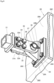
Fig. 4 is a perspective view showing the connection part between the cab support part and the reinforcing member of the vehicle body frame. -
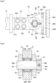
Fig. 5 is a left side view showing the connection part between the cab support part and the reinforcing member. -
Fig. 6 is a cross-sectional view of the connection part between the cab support part and the reinforcing member as seen from the direction of arrow VI-VI inFig. 5 . - Hereinafter, embodiments of the dump truck according to the present invention will be described in detail with reference to the accompanying drawings. In the embodiments, the traveling direction of the dump truck is described as the longitudinal direction, and the direction orthogonal to the traveling direction is described as the lateral direction.
- In the figures, the dump truck 1 comprises a self-propelled
vehicle body 2 equipped with left and rightfront wheels 3 and left and rightrear wheels 4, and avessel 5, described later, tiltably mounted on thevehicle body 2. The dump truck 1 transports materials such as crushed stone excavated from the mine by loading them onto thevessel 5. Thevehicle body 2 of the dump truck 1 is configured to include abuilding 7, adeck 8, acab 9, avehicle body frame 14, and the like, which will be described later. - The left and right
front wheels 3 are rotatably provided at the front side of thevehicle body 2, constituting steering wheels. Thefront wheels 3 are supported by thevehicle body frame 14 via a front wheel suspension (not shown), and vibrations transmitted from thefront wheels 3 to thevehicle body 2 are mitigated. The left and rightrear wheels 4 are rotatably provided at the rear side of thevehicle body 2 and are rotationally driven by a travel device (not shown) equipped with an electric motor. The travel device of therear wheels 4 is supported by thevehicle body frame 14 via a rear wheel suspension (not shown), and vibrations transmitted from therear wheels 4 to thevehicle body 2 are mitigated. - The
vessel 5 is tiltably (undulatively) mounted on thevehicle body frame 14. Thevessel 5 is formed as a large bottomed container for loading a large amount of minerals and the like excavated by, for example, a hydraulic excavator (not shown) . The rear bottom part of thevessel 5 is tiltably connected via a connectingpin 5B to left and rightrear end brackets 24, which will be described later, provided on thevehicle body frame 14. At the front side of thevessel 5, aneave part 5A extending horizontally forward from the upper part is integrally provided. Theeave part 5A of thevessel 5 extends to the front end side of thedeck 8 while covering thecab 9 from above. - The
hoist cylinder 6 is provided in pairs in the lateral direction between thevehicle body frame 14 and the vessel 5 (only the left side is shown) . Thehoist cylinder 6 is composed of, for example, a hydraulic cylinder and tilts the front side of thevessel 5 up and down relative to thevehicle body frame 14. One end side (lower end side) of thehoist cylinder 6 is pivotally attached to acylinder support shaft 26, which will be described later, and the other end side (upper end side) of thehoist cylinder 6 is pivotally attached to the lower surface side of thevessel 5. Therefore, by extending or retracting thehoist cylinder 6, the front side (eave part 5A side) of thevessel 5 rotates (moves up and down) in the vertical direction with the connectingpin 5B as a fulcrum. As a result, thevessel 5 tilts to a dumping position where the front side is lifted upward, allowing the discharge of the transported materials loaded on thevessel 5. - The
building 7 is provided at the front side of thevehicle body 2. Thebuilding 7 is formed in a rectangular frame shape enclosed by left and right side plates and a top plate, defining a machine room for accommodating mounted equipment such as an engine, a generator, and a hydraulic pump (all not shown). - The
deck 8 is positioned in front of thevessel 5 and is provided on theleft support column 22,right support column 23, and the upper side of thebuilding 7 of thevehicle body frame 14. Thedeck 8 is formed in an elongated rectangular flat plate shape in the lateral direction and is supported from below by anupper cross beam 28 and thebuilding 7, which will be described later. Thedeck 8 is arranged above the left and rightfront wheels 3 and extends in the horizontal direction, with thecab 9,control cabinet 10, and the like mounted on thedeck 8. In addition, the upper surface of thedeck 8 serves as a flat passage surface for operators and the like to pass through, and the outer periphery of thedeck 8 is surrounded bymultiple handrails 8A. - The
cab 9 is positioned at the front side of thevessel 5 and is provided on thevehicle body frame 14, covered from above by theeave part 5A. Thecab 9 consists of a box body enclosed by a front face, rear face, left and right side faces, top face, and bottom face, defining an operating room for the operator of the dump truck 1 to get on and off. Therear side part 9A of thecab 9 is supported from below by thecab support part 28E of theupper cross beam 28, and thefront side part 9B of thecab 9 is supported from below by afront support member 30, which will be described later. Inside thecab 9, there are provided a driver's seat, an accelerator pedal, a brake pedal, a steering handle, and multiple control levers (all not shown). - The
radiator 11 is provided at the front end side of thevehicle body frame 14. Theradiator 11 is arranged at the front side of thebuilding 7 and cools the engine coolant and the like of an engine (not shown) housed in the machine room defined by thebuilding 7. On both the left and right sides of theradiator 11,fenders 12 protruding in the lateral direction from the left and right side plates of thebuilding 7 are provided. Each of these left andright fenders 12 is equipped with anair cleaner 13. Theair cleaner 13 captures dust contained in the outside air at work sites such as mines and supplies clean air (intake air) to the engine. - The
vehicle body frame 14 serves as the base of thevehicle body 2 and constitutes a robust support structure. As shown inFig. 3 , thevehicle body frame 14 is configured to include amain frame 15 extending in the longitudinal direction and afront bumper 27 integrally fixed to the front side of themain frame 15. Themain frame 15 is composed of aleft frame 16, aright frame 17, afront frame 18, arear frame 19, anupper plate 20, alower plate 21, aleft support column 22, aright support column 23, anupper cross beam 28, and the like. - The
left frame 16 is positioned on the left side of thevehicle body frame 14 and extends in the longitudinal direction. Theleft frame 16 is composed of left andright side plates 16A facing each other in the lateral direction, anupper plate 20 closing the upper ends of theside plates 16A, and alower plate 21 connecting the lower ends of theside plates 16A. Theright frame 17 is positioned on the right side of thevehicle body frame 14 and extends in the longitudinal direction. Theright frame 17 is composed of left andright side plates 17A facing each other in the lateral direction, anupper plate 20 closing the upper ends of theside plates 17A, and alower plate 21 connecting the lower ends of theside plates 17A. - The
front frame 18 connects between the front end of theleft frame 16 and the front end of theright frame 17. Thefront frame 18 is composed of afront plate 18A and a rear plate (not shown) facing each other in the longitudinal direction, anupper plate 20 closing the upper ends of thefront plate 18A and the rear plate, and alower plate 21 closing the lower ends of thefront plate 18A and the rear plate. The left end of thefront frame 18 is joined to the front end of theleft frame 16 by welding, and the right end of thefront frame 18 is joined to the front end of theright frame 17 by welding. - The
rear frame 19 connects between the rear end of theleft frame 16 and the rear end of theright frame 17. Therear frame 19 is composed of a front plate and a rear plate (both not shown) facing each other in the longitudinal direction, anupper plate 20 closing the upper ends of the front and rear plates, and alower plate 21 closing the lower ends of the front and rear plates. The left end of therear frame 19 is joined to the rear end of theleft frame 16 by welding, and the right end of therear frame 19 is joined to the rear end of theright frame 17 by welding. - The
upper plate 20 closes the upper ends of theleft frame 16,right frame 17,front frame 18, andrear frame 19, and connects between theleft frame 16 and theright frame 17. The front side of theupper plate 20 forms abifurcated branch section 20A that closes the upper ends of theleft frame 16 and theright frame 17. The front end of thebranch section 20A is connected by a front connection section (not shown), which closes the upper end of thefront frame 18. - The
lower plate 21 closes the lower ends of theleft frame 16,right frame 17,front frame 18, andrear frame 19, and connects between theleft frame 16 and theright frame 17. The front side of thelower plate 21 forms abifurcated branch section 21A similar to theupper plate 20. The front end of thebranch section 21A is connected by afront connection section 21B, which closes the lower end of thefront frame 18. - The
left column 22 andright column 23 are provided at a position closer to the front from the central part in the longitudinal direction of thevehicle body frame 14, facing each other in the lateral direction. Theseleft column 22 andright column 23 are made of a hollow fabricated structure with a mountain shape. Theleft column 22 protrudes upward from theupper plate 20 constituting theleft frame 16, and theright column 23 protrudes upward from theupper plate 20 constituting theright frame 17. At the upper ends of theleft column 22 andright column 23, flat mounting flanges (only the mountingflange 22A of theleft column 22 is shown) are fixed. Theupper cross beam 28 is attached to the mountingflange 22A of theleft column 22 and the mounting flange of the right column 23 (not shown). - At the rear end of the
main frame 15, left and rightrear end brackets 24 are provided. Eachrear end bracket 24 protrudes rearward from the rear end of theupper plate 20 constituting theleft frame 16 andright frame 17, facing each other in the lateral direction. These left and rightrear end brackets 24 pivotally support the bottom part of thevessel 5 via connectingpins 5B. - On the lower side of the intermediate part in the longitudinal direction of the
main frame 15, left andright cylinder brackets 25 are provided. These left andright cylinder brackets 25 protrude downward from thelower plate 21 constituting theleft frame 16 andright frame 17, facing each other in the lateral direction. At the protruding end side of thecylinder bracket 25, acylinder support shaft 26 extending in the lateral direction is fixed, and the lower end side of the hoistcylinder 6 is pivotally attached to thiscylinder support shaft 26. - The
front bumper 27 is integrally fixed to the front side of thefront frame 18 constituting themain frame 15 using means such as welding. Thefront bumper 27 has a U-shaped cross-section formed by thefront frame section 27A, leftframe section 27B, andright frame section 27C, and is formed as a U-shaped bent frame body as a whole. Thefront frame section 27A extends in the lateral direction while facing thefront frame 18 in the longitudinal direction. Theleft frame section 27B connects between the left end of thefront frame section 27A and the left end of thefront frame 18. Theright frame section 27C connects between the right end of thefront frame section 27A and the right end of thefront frame 18. - The
upper cross beam 28 is attached to the upper ends of theleft column 22 andright column 23 and extends in the lateral direction. Theupper cross beam 28 is formed by a rectangular tube having a square cross-section enclosed by thefront face 28A,rear face 28B,top face 28C, andbottom face 28D. Thebottom face 28D of theupper cross beam 28 is fixed to the mountingflange 22A of theleft column 22 and the mounting flange of the right column 23 (not shown) . The left end side of theupper cross beam 28 becomes thecab support section 28E, and therear side part 9A of thecab 9 is attached to thetop face 28C of thecab support section 28E. Thus, thecab support section 28E of theupper cross beam 28 supports therear side part 9A of thecab 9 from below. Additionally, the part of theupper cross beam 28 located to the right of thecab support section 28E supports thedeck 8 from below along with thebuilding 7. - A
frame side bracket 29 is provided on thefront face 28A of thecab support section 28E. As shown inFIGS. 4 to 6 , theframe side bracket 29 has asquare base plate 29A and aprotruding plate 29B that protrudes forward from the central part in the lateral direction of thebase plate 29A. Thebase plate 29A is fixed to thefront face 28A of theupper cross beam 28 usingmultiple bolts 29C. As shown inFIG. 6 , abearing mounting hole 29D penetrating in the lateral direction is formed in the protrudingplate 29B of theframe side bracket 29. Theouter ring 34A of thespherical bearing 34, which will be described later, is attached to thebearing mounting hole 29D. - The
front support member 30 is provided between thevehicle body frame 14 and thecab 9. Thefront support member 30 is formed as a trapezoidal frame body having anupper frame section 30A, aleft frame section 30B, aright frame section 30C, and anoblique frame section 30D by joining, for example, square tubular pipes using means such as welding. Theupper frame section 30A extends in the lateral direction. Theleft frame section 30B hangs downward from the left end of theupper frame section 30A. Theright frame section 30C has a greater length dimension than theleft frame section 30B and hangs downward from the right end of theupper frame section 30A. Theoblique frame section 30D connects between the lower end of theleft frame section 30B and the lower end of theright frame section 30C, extending obliquely downward from theleft frame section 30B toward theright frame section 30C. - At the junction of the
right frame section 30C and theoblique frame section 30D of the front support member 30 (the lower end of the front support member 30), asquare mounting substrate 30E is provided. The mountingsubstrate 30E is fixed to theside plate 16A on the front end side of theleft frame 16 constituting thevehicle body frame 14 using bolts or the like. Thefront side part 9B of thecab 9 is attached to theupper frame section 30A of thefront support member 30. Thus, thefront support member 30 supports thefront side part 9B of thecab 9 from below. - Here, a left side panel (not shown) constituting the
building 7 is attached to theright frame section 30C of thefront support member 30, and thefront support member 30 constitutes a part (support member) of thebuilding 7. This allows for a reduction in the number of parts required to form thebuilding 7. Additionally, aleft fender 12 is fixed to the front face of theupper frame section 30A, leftframe section 30B, andright frame section 30C constituting thefront support member 30, and anair cleaner 13 is attached to thisfender 12. - The
reinforcement member 31 is provided between thecab support section 28E of theupper cross beam 28 and thefront support member 30, extending in the longitudinal direction. Thereinforcement member 31 is formed using a rectangular tube with a square cross-section, and a mounting flange (not shown) is provided on one end side (front end side) in the length direction of thereinforcement member 31. This mounting flange serves as the front connection section between the front end side of thereinforcement member 31 and thefront support member 30. The mounting flange is fixed to the upper part (upper end side of theupper frame section 30A or leftframe section 30B) of thefront support member 30 using fastening members such as bolts. - Meanwhile, the other end side (rear end side) in the length direction of the
reinforcement member 31 is connected to thecab support section 28E of theupper cross beam 28 by arear connection section 32. Therear connection section 32 is composed of theframe side bracket 29 provided on thecab support section 28E, the reinforcementmember side bracket 33 provided on thereinforcement member 31, and a connectingpin 36 to be described later. - Two reinforcement
member side brackets 33 are provided on the other end side (rear end side) in the length direction of thereinforcement member 31. The reinforcementmember side bracket 33 is fixed to thebracket mounting plate 31A, which is integrally provided on the rear end side of thereinforcement member 31, usingmultiple bolts 33A, facing each other in the lateral direction across thebracket mounting plate 31A. The rear end of the reinforcementmember side bracket 33 protrudes rearward from thebracket mounting plate 31A, and apin insertion hole 33B penetrating in the lateral direction is formed at this protruding end side. The two reinforcementmember side brackets 33 sandwich the protrudingplate 29B of theframe side bracket 29 from the left and right directions, and are arranged so that the pin insertion holes 33B of the reinforcementmember side brackets 33 and thebearing mounting holes 29D of the protrudingplate 29B are aligned concentrically. Then, the two reinforcementmember side brackets 33 are connected to the protrudingplate 29B of theframe side bracket 29 via the connectingpin 36 inserted into thepin insertion hole 33B and thespherical bearing 34. - The
spherical bearing 34 is provided at therear connecting part 32 between thecab support part 28E of theupper cross beam 28 and thereinforcement member 31. As shown inFIG. 6 , thespherical bearing 34 is configured to include anouter ring 34A attached to theframe side bracket 29 and aninner ring 34B attached to the connectingpin 36. The inner circumferential surface of theouter ring 34A is a concavespherical surface 34C, and the outer circumferential surface of theinner ring 34B is a convexspherical surface 34D that can slideably contact the concavespherical surface 34C of theouter ring 34A. Theouter ring 34A is inserted into thebearing mounting hole 29D formed in the protrudingplate 29B of theframe side bracket 29. Theouter ring 34A is fixed to the protrudingplate 29B in a state where it is sandwiched by two retainingrings 35 for holes on both axial sides. - The connecting
pin 36 is inserted into the two reinforcementmember side brackets 33 and theinner ring 34B of thespherical bearing 34. Specifically, the axial intermediate part of the connectingpin 36 fits into theinner ring 34B of thespherical bearing 34, and both axial sides of the connectingpin 36 are inserted into the pin insertion holes 33B of the two reinforcementmember side brackets 33, respectively. At one end of the connectingpin 36, apin hole 36A is formed that penetrates in a direction orthogonal to the axial direction through the center of the connectingpin 36. - On the outer surface of one of the two reinforcement
member side brackets 33, acylindrical member 37 is fixed concentrically with thepin insertion hole 33B. Thecylindrical member 37 has a throughhole 37A formed radially through its center. One end of the connectingpin 36, in which thepin hole 36A is formed, is positioned on the inner circumferential side of thecylindrical member 37 fixed to one of the reinforcementmember side brackets 33. Then, astopper bolt 38 is inserted into the throughhole 37A of thecylindrical member 37 and thepin hole 36A of the connectingpin 36. As a result, the connectingpin 36 fitted into theinner ring 34B of thespherical bearing 34 is rotationally secured and axially retained with respect to the reinforcementmember side bracket 33. - Between both axial ends of the
inner ring 34B constituting thespherical bearing 34 and the two reinforcementmember side brackets 33,annular spacers 39 are provided. Thespacer 39 is inserted into the connectingpin 36 and adjusts the gap A formed between the protrudingplate 29B of theframe side bracket 29 and the reinforcementmember side bracket 33. As a result, the reinforcementmember side bracket 33 and theframe side bracket 29 are relatively rotatably connected around theinner ring 34B of thespherical bearing 34 within the range of the gap A. - In this way, the
cab support part 28E of theupper cross beam 28 supporting therear side part 9A of thecab 9 and thefront support member 30 supporting thefront side part 9B of thecab 9 are connected by thereinforcement member 31. This reduces the load acting on thefront support member 30 during the travel of the dump truck 1. - Also, the
frame side bracket 29 provided on thecab support part 28E and the reinforcementmember side bracket 33 provided on thereinforcement member 31 are connected via the connectingpin 36. Aspherical bearing 34 is provided between the connectingpin 36 and the frame side bracket 29 (protrudingplate 29B). As a result, even if torsional deformation occurs in thevehicle body frame 14 when the dump truck 1 travels over uneven ground, the reinforcementmember side bracket 33 and theframe side bracket 29 rotate relative to each other around theinner ring 34B of thespherical bearing 34. This allows the torsional deformation of thevehicle body frame 14 to be absorbed. Therefore, it is possible to suppress the load due to the torsional deformation of thevehicle body frame 14 from acting on the connection part between thecab support part 28E and thereinforcement member 31. - The dump truck 1 according to this embodiment has the above-described configuration, and when transporting crushed stone from a mine or the like using the dump truck 1, the operator on board the
cab 9 starts the engine. As a result, the engine drives a hydraulic pump, a generator, etc. (none of which are shown). The power from the generator is supplied to the electric motor of the travel device, and by rotationally driving therear wheels 4, the dump truck 1 travels to the quarry. Then, crushed stone excavated using a large hydraulic excavator or similar equipment (not shown) is loaded onto thevessel 5 of the dump truck 1, which has stopped at the quarry. The dump truck 1 loaded with crushed stone travels to the collection site, then discharges the crushed stone at the collection site by tilting thevessel 5 using the hoistcylinder 6. - The dump truck 1 travels on rough terrain (uneven ground) in mines and the like, causing the
vehicle body frame 14 to undergo torsional deformation. As a result, thereinforcement member 31 connecting thecab support part 28E of theupper cross beam 28 and thefront support member 30 is subjected to a load due to the torsional deformation of thevehicle body frame 14. In contrast, in this embodiment, aspherical bearing 34 is provided between the rear connectingpart 32 of thecab support part 28E and thereinforcement member 31, that is, between theframe side bracket 29 and the reinforcementmember side bracket 33 connected via the connectingpin 36. - Therefore, even if torsional deformation occurs in the
vehicle body frame 14, the reinforcementmember side bracket 33 and theframe side bracket 29 rotate relative to each other around theinner ring 34B of thespherical bearing 34, allowing the torsional deformation of thevehicle body frame 14 to be absorbed. This suppresses the load due to the torsional deformation of thevehicle body frame 14 from acting on the connection part between thecab support part 28E and thereinforcement member 31. As a result, the dump truck 1 according to this embodiment does not need to increase the rigidity of thevehicle body frame 14 or the strength of thereinforcement member 31 to suppress the torsional deformation of thevehicle body frame 14, and can enhance the support strength of thecab 9 without increasing the weight of the vehicle body. - Thus, in the embodiment, the dump truck 1 includes a
vehicle body frame 14 extending in the longitudinal direction with wheels attached, avessel 5 tiltably provided with respect to thevehicle body frame 14 for loading transported materials, and acab 9 provided on thevehicle body frame 14 at the front side of thevessel 5 and to define an operating room. In the dump truck 1, thevehicle body frame 14 is provided with acab support part 28E supporting therear side part 9A of thecab 9, afront support member 30 disposed between thevehicle body frame 14 and thecab 9 to support thefront side part 9B of thecab 9, and areinforcement member 31 connecting thefront support member 30 and thecab support part 28E. And at least one of the connection parts between thecab support part 28E and the reinforcement member 31 (rear connecting part 32), and between thefront support member 30 and the reinforcement member 31 (front connecting part), is provided with aspherical bearing 34. - According to this configuration, even if torsional deformation occurs in the
vehicle body frame 14 during the travel of the dump truck 1, the reinforcementmember side bracket 33 of thereinforcement member 31 connected via the connectingpin 36 and theframe side bracket 29 of thecab support part 28E rotate relative to each other around theinner ring 34B of thespherical bearing 34. This allows the torsional deformation of thevehicle body frame 14 to be absorbed. Therefore, it is possible to suppress the load due to the torsional deformation of thevehicle body frame 14 from acting on therear connecting part 32 between thecab support part 28E and thereinforcement member 31, and to enhance the support strength of thecab 9 without increasing the weight of thevehicle body 2. - In the embodiment, the
cab support part 28E is provided with aframe side bracket 29, and thereinforcement member 31 is provided with a reinforcementmember side bracket 33 connected to theframe side bracket 29 via the connectingpin 36. Thespherical bearing 34 includes anouter ring 34A with a concavespherical surface 34C attached to theframe side bracket 29, and aninner ring 34B with a convexspherical surface 34D attached to the connectingpin 36 and slidingly contacting the concavespherical surface 34C of theouter ring 34A. According to this configuration, even if torsional deformation occurs in thevehicle body frame 14 during the travel of the dump truck 1, the reinforcementmember side bracket 33 and theframe side bracket 29 rotate relative to each other around theinner ring 34B of thespherical bearing 34, allowing the torsional deformation of thevehicle body frame 14 to be absorbed. - In the embodiment, the
front support member 30 constitutes a part of thebuilding 7 that defines a machine room at the front side of thevehicle body frame 14. According to this configuration, since thefront support member 30 supporting thefront side part 9B of thecab 9 also serves as a part of thebuilding 7, the number of parts required to form thebuilding 7 can be reduced. - In the embodiment, an example is illustrated where a
spherical bearing 34 is provided at therear connecting part 32 between the rear end of thereinforcement member 31 and thecab support part 28E. However, the present invention is not limited to this, and a configuration in which a spherical bearing is provided at the front connecting part between the front end of thereinforcement member 31 and thefront support member 30 may also be employed. Furthermore, a configuration in which spherical bearings are provided at both therear connecting part 32 between the rear end of thereinforcement member 31 and thecab support part 28E, and the front connecting part between the front end of thereinforcement member 31 and thefront support member 30 may also be employed. -
- 1 : Dump truck
- 2 : Vehicle body
- 3 : Front wheel
- 4 : Rear wheel
- 5 : vessel
- 9 : Cab
- 9A : Rear side part
- 9B : Front side part
- 14 : Vehicle body frame
- 28 : Upper cross beam
- 28E : Cab support part
- 29 : Frame side bracket
- 30 : Front support member
- 31 : Reinforcement member
- 32: Rear connection part (connection part)
- 33: Reinforcement member side bracket
- 34: Spherical bearing
- 34A : Outer ring
- 34B : Inner ring
- 34C : concave spherical surface
- 34D : convex spherical surface
Claims (3)
- A dump truck comprising:a vehicle body frame to which wheels are attached and which extends in the longitudinal direction;a vessel that is tiltably mounted on the vehicle body frame for loading to-be-transported materials anda cab located at the front side of the vessel and provided on the vehicle body frame to define the operating room, whereinthe vehicle body frame is provided with a cab support part supporting the rear side part of the cab, a front support member disposed between the vehicle body frame and the cab to support the front side part of the cab, and a reinforcement member connecting the front support member and the cab support part, anda spherical bearing is provided with, at least one of the connection points between the cab support and the reinforcement member and between the front support member and the reinforcement member.
- The dump truck according to claim 1, whereinthe cab support part is provided with a frame side bracket,the reinforcement member is provided with a reinforcement member side bracket connected to the frame side bracket via a connecting pin, andthe spherical bearing includes an outer ring having a concave spherical surface attached to the frame side bracket, and an inner ring having a convex spherical surface attached to the connecting pin and slidingly contacting the concave spherical surface of the outer ring.
- The dump truck according to claim 1, wherein
the front support member constitutes a part of a deck defining a machine room at the front side of the vehicle body frame.
Applications Claiming Priority (2)
| Application Number | Priority Date | Filing Date | Title |
|---|---|---|---|
| JP2022156839A JP7382473B1 (en) | 2022-09-29 | 2022-09-29 | Dump truck |
| PCT/JP2023/030643 WO2024070370A1 (en) | 2022-09-29 | 2023-08-25 | Dump truck |
Publications (2)
| Publication Number | Publication Date |
|---|---|
| EP4566920A1 true EP4566920A1 (en) | 2025-06-11 |
| EP4566920A4 EP4566920A4 (en) | 2026-07-29 |
Family
ID=88729236
Family Applications (1)
| Application Number | Title | Priority Date | Filing Date |
|---|---|---|---|
| EP23871611.2A Pending EP4566920A4 (en) | 2022-09-29 | 2023-08-25 | DUMP TRUCK |
Country Status (5)
| Country | Link |
|---|---|
| US (1) | US20260091830A1 (en) |
| EP (1) | EP4566920A4 (en) |
| JP (1) | JP7382473B1 (en) |
| CN (1) | CN119677663A (en) |
| WO (1) | WO2024070370A1 (en) |
Family Cites Families (11)
| Publication number | Priority date | Publication date | Assignee | Title |
|---|---|---|---|---|
| JPS50138560A (en) * | 1974-04-24 | 1975-11-05 | ||
| US3977489A (en) * | 1975-01-24 | 1976-08-31 | Caterpillar Tractor Co. | Framework for a wheeled self-propelled truck |
| JPH0244580U (en) * | 1988-09-22 | 1990-03-27 | ||
| BR9106807A (en) * | 1990-09-03 | 1993-07-13 | Broken Hill Pty Co Ltd | SUSPENSION AND BODY SYSTEM FOR LARGE TILT WAYS |
| JPH0465681U (en) * | 1990-10-15 | 1992-06-08 | ||
| US5273317A (en) * | 1992-03-12 | 1993-12-28 | Komatsu Dresser Company | Off highway truck frame |
| US6135225A (en) | 1999-06-30 | 2000-10-24 | Caterpillar Inc. | Tilt mechanism for supporting a cab assembly of a work machine and an associated method of operating a tilt mechanism of a work machine |
| US8235156B2 (en) | 2007-05-26 | 2012-08-07 | Micheal James Koss | Retrofitable ROPS reinforcement structure for cab raiser interface |
| US9482139B2 (en) * | 2014-12-01 | 2016-11-01 | Komatsu Ltd. | Dump truck |
| JP6696944B2 (en) | 2017-09-06 | 2020-05-20 | 日立建機株式会社 | Dump truck |
| JP6805122B2 (en) | 2017-12-26 | 2020-12-23 | 日立建機株式会社 | Transport vehicle |
-
2022
- 2022-09-29 JP JP2022156839A patent/JP7382473B1/en active Active
-
2023
- 2023-08-25 WO PCT/JP2023/030643 patent/WO2024070370A1/en not_active Ceased
- 2023-08-25 EP EP23871611.2A patent/EP4566920A4/en active Pending
- 2023-08-25 US US19/110,943 patent/US20260091830A1/en active Pending
- 2023-08-25 CN CN202380061585.5A patent/CN119677663A/en active Pending
Also Published As
| Publication number | Publication date |
|---|---|
| EP4566920A4 (en) | 2026-07-29 |
| JP7382473B1 (en) | 2023-11-16 |
| CN119677663A (en) | 2025-03-21 |
| US20260091830A1 (en) | 2026-04-02 |
| JP2024050164A (en) | 2024-04-10 |
| WO2024070370A1 (en) | 2024-04-04 |
Similar Documents
| Publication | Publication Date | Title |
|---|---|---|
| US8104842B2 (en) | Transporter vehicle | |
| US7665801B2 (en) | Structure of upper frame for supporting cabin of construction machinery | |
| JP6613363B2 (en) | Dump body for dump truck and dump truck | |
| US20260091830A1 (en) | Dump truck | |
| JP6218047B2 (en) | Dump truck | |
| US10723253B2 (en) | Front tower for machine | |
| EP3372425A1 (en) | A working machine | |
| US20240286661A1 (en) | Wheeled platform for external charger and method for transporting external charger | |
| JP5785504B2 (en) | Transport vehicle | |
| JP7824805B2 (en) | Electric construction machinery and its manufacturing method | |
| JP2019043481A (en) | Dump truck | |
| CN101758850A (en) | Steering column assembly structure | |
| JP7374276B1 (en) | Dump truck | |
| JP5941418B2 (en) | Work vehicle | |
| JP6676797B2 (en) | Lorry | |
| JP2025044336A (en) | Dump truck | |
| CN107921831A (en) | The installation constitution and working truck of suspension link | |
| CN113728140A (en) | Working vehicle | |
| WO2006033311A1 (en) | Working machine | |
| US20230278628A1 (en) | Steering bracket for construction machine | |
| JP2013112250A (en) | Vessel support structure of dump truck | |
| JP2002046657A (en) | Reinforcement structure of crawler type rough terrain vehicle when it falls over | |
| JP4824996B2 (en) | Cab structure | |
| JP4994964B2 (en) | Construction machinery | |
| JP2012136052A (en) | Carrier connection structure of dump truck |
Legal Events
| Date | Code | Title | Description |
|---|---|---|---|
| STAA | Information on the status of an ep patent application or granted ep patent |
Free format text: STATUS: THE INTERNATIONAL PUBLICATION HAS BEEN MADE |
|
| PUAI | Public reference made under article 153(3) epc to a published international application that has entered the european phase |
Free format text: ORIGINAL CODE: 0009012 |
|
| STAA | Information on the status of an ep patent application or granted ep patent |
Free format text: STATUS: REQUEST FOR EXAMINATION WAS MADE |
|
| 17P | Request for examination filed |
Effective date: 20250306 |
|
| AK | Designated contracting states |
Kind code of ref document: A1 Designated state(s): AL AT BE BG CH CY CZ DE DK EE ES FI FR GB GR HR HU IE IS IT LI LT LU LV MC ME MK MT NL NO PL PT RO RS SE SI SK SM TR |
|
| DAV | Request for validation of the european patent (deleted) | ||
| DAX | Request for extension of the european patent (deleted) | ||
| A4 | Supplementary search report drawn up and despatched |
Effective date: 20260624 |
|
| RIC1 | Information provided on ipc code assigned before grant |
Ipc: B62D 21/02 20060101AFI20260623BHEP Ipc: B62D 33/06 20060101ALI20260623BHEP Ipc: B60P 1/28 20060101ALI20260623BHEP Ipc: B62D 21/18 20060101ALI20260623BHEP |