EP4566914A1 - Vehicle steering wheel device - Google Patents
Vehicle steering wheel device Download PDFInfo
- Publication number
- EP4566914A1 EP4566914A1 EP23862943.0A EP23862943A EP4566914A1 EP 4566914 A1 EP4566914 A1 EP 4566914A1 EP 23862943 A EP23862943 A EP 23862943A EP 4566914 A1 EP4566914 A1 EP 4566914A1
- Authority
- EP
- European Patent Office
- Prior art keywords
- bushing
- steering wheel
- plate member
- locking
- hole
- Prior art date
- Legal status (The legal status is an assumption and is not a legal conclusion. Google has not performed a legal analysis and makes no representation as to the accuracy of the status listed.)
- Pending
Links
Images






Classifications
-
- B—PERFORMING OPERATIONS; TRANSPORTING
- B62—LAND VEHICLES FOR TRAVELLING OTHERWISE THAN ON RAILS
- B62D—MOTOR VEHICLES; TRAILERS
- B62D1/00—Steering controls, i.e. means for initiating a change of direction of the vehicle
- B62D1/02—Steering controls, i.e. means for initiating a change of direction of the vehicle vehicle-mounted
- B62D1/04—Hand wheels
- B62D1/10—Hubs; Connecting hubs to steering columns, e.g. adjustable
-
- B—PERFORMING OPERATIONS; TRANSPORTING
- B62—LAND VEHICLES FOR TRAVELLING OTHERWISE THAN ON RAILS
- B62D—MOTOR VEHICLES; TRAILERS
- B62D1/00—Steering controls, i.e. means for initiating a change of direction of the vehicle
- B62D1/02—Steering controls, i.e. means for initiating a change of direction of the vehicle vehicle-mounted
- B62D1/04—Hand wheels
-
- B—PERFORMING OPERATIONS; TRANSPORTING
- B60—VEHICLES IN GENERAL
- B60R—VEHICLES, VEHICLE FITTINGS, OR VEHICLE PARTS, NOT OTHERWISE PROVIDED FOR
- B60R21/00—Arrangements or fittings on vehicles for protecting or preventing injuries to occupants or pedestrians in case of accidents or other traffic risks
- B60R21/02—Occupant safety arrangements or fittings, e.g. crash pads
- B60R21/16—Inflatable occupant restraints or confinements designed to inflate upon impact or impending impact, e.g. air bags
- B60R21/20—Arrangements for storing inflatable members in their non-use or deflated condition; Arrangement or mounting of air bag modules or components
- B60R21/203—Arrangements for storing inflatable members in their non-use or deflated condition; Arrangement or mounting of air bag modules or components in steering wheels or steering columns
- B60R21/2035—Arrangements for storing inflatable members in their non-use or deflated condition; Arrangement or mounting of air bag modules or components in steering wheels or steering columns using modules containing inflator, bag and cover attachable to the steering wheel as a complete sub-unit
- B60R21/2037—Arrangements for storing inflatable members in their non-use or deflated condition; Arrangement or mounting of air bag modules or components in steering wheels or steering columns using modules containing inflator, bag and cover attachable to the steering wheel as a complete sub-unit the module or a major component thereof being yieldably mounted, e.g. for actuating the horn switch or for protecting the driver in a non-deployment situation
-
- B—PERFORMING OPERATIONS; TRANSPORTING
- B62—LAND VEHICLES FOR TRAVELLING OTHERWISE THAN ON RAILS
- B62D—MOTOR VEHICLES; TRAILERS
- B62D7/00—Steering linkage; Stub axles or their mountings
- B62D7/22—Arrangements for reducing or eliminating reaction, e.g. vibration, from parts, e.g. wheels, of the steering system
- B62D7/222—Arrangements for reducing or eliminating reaction, e.g. vibration, from parts, e.g. wheels, of the steering system acting on the steering wheel
-
- B—PERFORMING OPERATIONS; TRANSPORTING
- B60—VEHICLES IN GENERAL
- B60R—VEHICLES, VEHICLE FITTINGS, OR VEHICLE PARTS, NOT OTHERWISE PROVIDED FOR
- B60R21/00—Arrangements or fittings on vehicles for protecting or preventing injuries to occupants or pedestrians in case of accidents or other traffic risks
- B60R21/02—Occupant safety arrangements or fittings, e.g. crash pads
- B60R21/16—Inflatable occupant restraints or confinements designed to inflate upon impact or impending impact, e.g. air bags
- B60R21/20—Arrangements for storing inflatable members in their non-use or deflated condition; Arrangement or mounting of air bag modules or components
- B60R21/203—Arrangements for storing inflatable members in their non-use or deflated condition; Arrangement or mounting of air bag modules or components in steering wheels or steering columns
Definitions
- the present invention relates to a vehicle steering wheel device capable of improving durability of a mounting and fixing portion of a coil spring when an accessory member or an accessory component is mounted on a steering wheel of a vehicle in an elastically supported state via the coil spring.
- a steering wheel includes a steering wheel body, and an airbag module attached to the steering wheel body via a horn plate and a plurality of damper units.
- the damper unit includes a protector, a rubber bushing, and a resin bushing.
- a coil spring is interposed between the leg piece portion and the core metal portion of the protector in a state of force accumulation.
- Patent Document 2 entitled “Steering Wheel” a tip end portion of a pin protruding from an airbag module protrudes from a back-side surface of a horn plate through a tubular guide member provided in the horn plate. A tapered surface is provided on the tip side of the pin, and a lock spring provided on the back-side surface of the horn plate is pressed against the tapered surface.
- the airbag module is pressed against the rubber mount provided on the pedestal portion of the horn plate, and the mount seat portion is compressed.
- the distance between the horn switch and the rubber mount is equal to or less than 15 mm.
- the steering wheel serves as a transmission path of vibration such as traveling vibration from a road surface. For this reason, vibration is input to various accessory members and various accessory parts to the steering wheel, and vibration is also input to the coil spring interposed between the steering wheel and these accessory members and the like. As a result, it is considered that backlash occurs in the attachment fixing portion of the coil spring, and a countermeasure capable of improving the durability of the attachment fixing portion has been desired.
- a vehicle steering wheel device comprises: a holding plate configured to hold an accessory member to a steering wheel of a vehicle; an assembling plate member which is provided so as to be overlaid on the holding plate member and to which an accessory component to the steering wheel is assembled; a coil spring elastically supporting, on the steering wheel, the assembling plate member on which the holding plate member is overlaid; and a bushing inserted through both of the holding plate member and the assembling plate member to fix the coil spring, wherein the bushing is locked and fixed to the assembling plate member by means of a first locking means, and wherein the bushing fixed to the assembling plate member by means of the first locking means is locked and fixed to the holding plate member by means of a second locking means.
- the first locking means should include: a first through-hole which is formed around the bushing in the assembling plate and through which the bushing is inserted so as to be rotatable about the bushing; a plurality of hooks formed at intervals in the bushing so as to be elastically bendable around the bushing; a pressing collar portion which is formed in the first through-hole toward an inner side of the first through-hole and which elastically bends the hooks moved by the rotation of the bushing; a pair of engaging portions formed on the bushing and configured to be engaged with the pressing collar portion from both a front side and a back side by the rotation of the bushing so as to support the bushing on the assembling plate member; and a groove portion formed in the pressing collar portion and configured to elastically restore the hook moved by the rotation of the bushing and to lock the hook so as to prevent the rotation of the bushing.
- the second locking means should include: a second through-hole which is formed in the holding plate member and through which the bushing locked and fixed to the assembling plate member by the first locking means is inserted; and a stopper projection formed on the bushing outward from the bushing, wherein the second through-hole has a locking collar portion formed toward the inside of the second through-hole and locking the stopper projection so as to suppress the rotation of the bushing.
- the durability of the attachment and fixing portion of the coil spring can be improved.
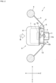
- FIG. 1 to FIG. 6 illustrate a vehicle steering wheel 1 and an airbag module 2 attached thereto.
- FIG. 1 is a perspective view generally illustrating a steering wheel 1 to which an airbag module 2 is attached.
- FIG. 2 is a side cross-sectional view thereof.
- each direction is illustrated with an assumption that the steering wheel 1 mounted on the vehicle is in the neutral steering position.
- the neutral steering position refers to a position where the steering angle of the steering wheel 1 is "zero" and the steered front wheels face in a straight direction.
- the Z axis of the three-dimensional coordinate system (hereinafter, also referred to as "Z axis direction”) is an axis parallel to the rotation axis of an unillustrated steering shaft.
- the directions of the Z axis are: a downward direction, which is a direction, along the steering shaft, toward the front wheels; and an upward direction, which is a direction toward the steering wheel 1.
- the Z-axis directions are directions parallel to the axis of a coil spring 24, which is described later.
- the Z-axis directions are also parallel to a direction in which the housing 9 serving as a holding plate member and the locking plate 8 serving as an assembling plate member are overlapped with each other.
- the directions of the X-axis of the three-dimensional coordinate system are from the 3 o'clock direction (right-hand side) to the 9 o'clock direction (left-hand side), and vise versa, of an analog clock on a plane perpendicular to the Z-axis
- the directions of the Y-axis are from the 12 o'clock direction (upside) to the 6 o'clock direction (downside), and vise versa, thereof on the same plane.
- the side seen from the side of the driver shall be described as the front side and the opposite side as the back side.
- the steering wheel 1 is installed on the driver's seat side of the vehicle, and is connected to the steering shaft to transmit the steering operation by the driver to the steering gear and the like.
- An airbag module 2 which functions as a driver's seat airbag in the event of an emergency, is provided in the center of the steering wheel 1.
- the airbag module 2 functions as a horn switch, which the driver presses to cause the horn to sound.
- the airbag module 2 further functions as a module damper for damping vibrations of the steering wheel 1.
- the steering wheel 1 is made of a metal and is primarily composed of a center boss section 3, a rim 4 for the driver to grip, and spokes 5, which connect the boss section 3 and the rim 4. To the boss section 3, the steering shaft is connected.
- the airbag module 2 on the driver side is covered with a horn cover 6, which is made of resin and functions as a design surface.
- an airbag cushion 7 is accommodated in a folded state. In the event of an emergency, the airbag cushion 7 is deployed and expanded.
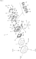
- the airbag module 2 is composed of: a metal locking plate 8; a metal housing 9 formed in a dish shape with a peripheral wall 9a provided on the front surface side thereof and with its plate surface overlaid on the surface of the locking plate 8; two hollow tubular damper units 10; pins 11 slidably inserted into hollow interiors of their respective damper units 10 and thus connecting the airbag module 2 to the boss section 3 of the steering wheel 1; a coupling member 12 provided on the housing 9, formed in a hook shape configured to be locked by the boss section 3 of the steering wheel 1, and configured to slide in the Z-axis direction to couple the airbag module 2 with the boss section 3; an inflator 13 supplying an inflator gas to the airbag cushion 7; a metal retainer ring 15 having a bolt 15a to which a nut 14 is fastened to fix the airbag cushion 7, the inflator 13, and the like to the housing 9; and the horn cover 6, which accommodates the airbag cushion 7.
- the damper unit 10 is an exemplar accessory component to the steering wheel 1, and is assembled to a locking plate 8 serving as an assembling plate member.
- the airbag cushion 7 is an exemplar accessory member to the steering wheel 1, and is held by a housing 9 serving as a holding plate member.
- the damper unit 10 is a member for elastically mounting the airbag module 2 to the steering wheel 1, and forms the central portion of the module damper.
- the damper unit 10 is configured by housing, inside a holder 17, a ring-shaped elastic body 16 for damping vibrations, and locking an insulator plate 18 overlaid on an end of the elastic body 16 with a sleeve 19, which is inserted into and retained within the elastic body 16.
- Each of the pins 11 provided in the damper unit 10 has a flange portion 11a at an end portion thereof.
- the pin 11 is inserted into the corresponding damper unit 10 from the housing 9 side so that the flange portion 11a abuts against the sleeve 19 of the damper unit 10.
- the two damper units 10 are arranged side by side in the X-axis directions with the neutral position of the steering wheel 1 serving as a reference, and are disposed on both the left-hand and right-hand sides of the airbag module 2.
- the two damper units 10 are provided at positions in the 3 o'clock and 9 o'clock directions of the analog clock with respect to the central axis (steering shaft) of the steering wheel 1.
- Each of the pins 11 is provided so as to protrude in an Z-axis direction from the damper unit 10 toward the boss section 3 of the steering wheel 1.
- the housing 9 and the locking plate 8 are described below with reference to FIG. 3 , FIG. 5A , and FIG. 6A .
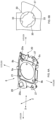
- FIG. 5A is a perspective view of the housing 9 as viewed from the back-side surface thereof
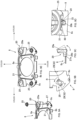
- FIG. 6A is a perspective view of the locking plate 8 as viewed from the back side thereof.
- the locking plate 8 is provided with a hole 8a for mounting the inflator.
- the hole 8a is formed through the center of the locking plate 8.
- the locking plate 8 is also provided with two recessed groove-like holding portions 20, which are formed in alignment with the arrangement of the two damper units 10 at positions separated from the hole 8a.
- a locking hole 20a for locking and fixing the holder 17 of the damper unit 10 is formed through each of the holding portions 20.
- An exemplar fixing structure for fixing the damper unit 10 to the locking hole 20a includes: the locking hole 20a and the holder 17 each formed in an elliptical shape defined by a long axis and a short axis.
- the holder 17 is inserted into the locking hole 20a by aligning the long axis and the short axis of the locking hole 20a with the long axis and the short axis of the holder 17, respectively. After that, the holder 17 is rotated to lock the holder 17 in the locking hole 20a. As a result, the damper unit 10 is assembled to the locking plate 8.
- a pointed head portion 11b formed at an end portion opposite to the flange portion 11a protrudes from the locking hole 20a toward the boss section 3 of the steering wheel 1 (see FIG. 4 ).
- the housing 9 is formed in a size capable of covering substantially the entire locking plate 8 including the holding portions 20.
- a hole portion 9b is formed in the center thereof for passing the inflator 13 therethrough. Also in the housing 9, a peripheral wall 9a is formed at the outer edge position so as to be raised on the front side.
- an assembly protrusion 8b is formed in the locking plate 8 and a locking bore 9c is formed in the housing so that the assembly protrusion 8b can fit in the locking bore 9c.
- an elastically deformable locking piece 6b formed on the tubular portion 6a of the horn cover 6 of the airbag module 2 is locked in the locking bore 9c of the housing 9.
- Locking the locking piece 6c in the locking bore 9c attaches the horn cover 6 accommodating the airbag cushion 7 to the housing 9.
- bolt insertion bores 21 are formed in the housing 9 and the locking plate 8. Bolts 15a of the retainer ring 15 are inserted into and through the bolt insertion bores 21.
- the coupling member 12 provided in the housing 9 has a joining part 12a joined to a peripheral wall 9a of the housing 9 with a rivet 22 at an end along a Z-axis direction, and also has a hook portion 12b locked to a boss section 3 of a steering wheel 1 at the other end.
- the coupling member 12 is formed of, for example, an elastically deformable plate-shaped metal plate or the like.
- the coupling member 12 is provided, in parallel with the damper unit 10, between the steering wheel 1 and the airbag module 2 described above.
- the hook portion 12b is covered with a resin-made elastic material 23 to electrically insulate the boss section 3 and the housing 9 from each other and to provide a cushioning effect.
- the coupling member 12 has an opening 12c extending in the Z-axis directions between the joining portion 12a and the hook portion 12b.
- a protruding portion (not illustrated) of the boss section 3 is inserted into the opening 12c.
- the airbag module 2 is slidable in the Z-axis directions with respect to the boss section 3 by the length of the opening 12c measured in the Z-axis directions.
- the pins 11 and the coupling member 12 are components for attaching the airbag module 2 to the boss section 3 of the steering wheel 1 from a Z-axis direction.
- the coupling member 12 is positioned in the lower side of the steering wheel 1 in the vertical directions (Y-axis directions) with the neutral position of the steering wheel 1 as the reference.
- the coupling member 12 is provided at a position in the direction of 6 o'clock of the analog clock with respect to the center axis (steering shaft) of the steering wheel 1.
- the coupling member 12 is arranged in the center between the two damper units 10, at a position lower than (on the 6 o'clock side of) these damper units 10.
- damper units 10 and the coupling member 12 are provided at their corresponding vertexes of an inverted isosceles triangle with respect to the airbag module 2.
- the airbag module 2 is provided with a pair of coil springs 24 on both sides of the coupling member 12 in the X-axis directions via bushings 25.
- the axis of each of the coil springs 24 is parallel to the Z-axis directions.
- the axis of each of the coil springs 24 refers to a line passing through the center of that coil spring 24 (also referred to as the coil spring axis).
- the coil springs 24 are disposed on the back-side surface 8c of the locking plate 8 and are held between the boss section 3 and the airbag module 2.
- the inflator 13 has an outer peripheral flange 13a, which has bolt insertion bores 21 and abuts against the back-side surface of the locking plate 8.
- the airbag cushion 7 has an insertion hole formed therein, into which the inflator 13 is inserted.
- Bolt insertion holes for inserting the bolts of the retainer ring 15 are formed around the insertion hole.
- the retainer ring 15 is provided inside the airbag cushion 7.
- the retainer ring 15 has a hole 15b which communicates with the hole 9b of the housing 9 and the hole 8a of the locking plate 8.
- the hole 15b allows the inflater 13 to be positioned in the airbag cushion 7.
- the retainer ring 15 is aligned with the insertion hole of the airbag cushion 7 so that the bolts 15a project from their respective bolt insertion bores.
- the insertion hole of the airbag cushion 7 is aligned with the hole 9b of the housing 9, and the bolts 15a of the retainer ring 15 protruding from the airbag cushion 7 are inserted into their respective bolt insertion bores 21 of the housing 9.
- the housing 9 holds the airbag cushion 7, which is an accessory member to the steering wheel 1.
- the damper units 10 are secured via their respective locking holes 20a after the damper units 10 are attached inside their respective holding portions 20 from the front-side surface side (housing 9 side) of the locking plate 8.
- a pointed end portion 11b is inserted into the corresponding damper unit 10 from the housing 9 side and protrudes out through the corresponding locking hole 20a of the locking plate 8.
- the housing 9 is put on the locking plate 8 from the front side, and the housing 9 and the locking plate 8 are overlaid one upon the other.
- the overlapping direction is parallel to the Z-axis directions.
- each of the pins 11 is held between the housing 9 and the locking plate 8 and is retained therebetween.
- the outer peripheral flange 13a of the inflator 13 is made to abut the back-side surface 8c of the locking plate 8.
- the inflator 13 is thus inserted into the insertion hole of the airbag cushion 7 through the hole 8a of the locking plate 8, the hole 9b of the housing 9, and the hole 15b of the retainer ring 15.
- the bolts 15a of the retainer ring 15 protruding from their respective bolt insertion bores 21 of the housing 9 are inserted into their respective bolt insertion bores 21 of the locking plate 8 and their respective bolt insertion bores 21 of the outer peripheral flange 13a of the inflator 13.
- Nuts 14 are provided on the back side of the locking plate 8 to fasten their respective bolts 15a.
- the airbag cushion 7 and the inflator 13 are secured to and held by the housing 9, and the damper units 10, which are accessory components to the steering wheel 1, are assembled onto the locking plate 8.
- the coupling member 12 attached to the housing 9 is arranged in parallel with the damper units 10 along the Z-axis directions.
- the horn cover 6 is attached to the housing 9.
- the locking piece 6b is locked in the locking bore 9c of the housing 9.
- coiled horn springs 26 which are elastically deformable elastic members, are provided between the boss section 3 and the locking plate 8 so as to surround the pins 11.
- a pair of coil springs 24 are attached to each of the bushings 25 located on both sides of the coupling member 12.
- the coil springs and the horn springs 26 are made to abut the boss section 3, and thus elastically support the airbag module 2 for the steering wheel 1.
- the horn springs 26 secure a gap located between the boss section 3 and the airbag module 2, and the gap is provided for horn operations.
- the pins 11, specifically their respective pointed end portions 11b are inserted into and held in their respective attachment bores (not illustrated) formed in the boss section 3, with the coil springs 24 and the horn springs 26 in an elastically compressed state.
- the hook portion 12b of the coupling member 12 is locked with the boss section 3.
- the airbag module 2 is thus attached and coupled to the steering wheel 1 in the Z-axis directions via the damper units 10 and the coupling member 12.
- the airbag module 2 is elastically supported, via the damper units 10, by the horn spring 26 relative to the steering wheel 1, with the airbag module 2 coupled to the steering wheel 1 so as to be movable (i.e., so as to be capable of being pressed) toward the steering wheel 1 (see FIG. 2B).
- the damper units 10 which are disposed between the airbag module 2 and the steering wheel 1, damp vibrations of the steering wheel 1.
- the vibrations of the steering wheel 1 are transmitted to the damper units 10 via their respective pins 11.
- the transmitted vibrations are damped by the elastic body 16 of the damper units 10, with the airbag module 2 serving as a damper mass.
- the inflator gas is supplied from the inflator 13 to the airbag cushion 7.
- the airbag cushion 7 ruptures the horn cover 6 and is expanded and deployed into the vehicle interior space to restrain the driver.
- the horn function When the airbag module 2 is pressed in the Z-axis direction toward the steering wheel 1, the entire airbag module 2 including the damper units 10 slides against the pins 11 retained in the boss section 3, and the horn springs 26 are elastically compressed and deformed.
- the contacts provided on the airbag module 2 and on the boss section 3 are electrically connected with each other, thereby causing the horn to sound.
- each of the horn springs 26 is elastically restored to the original shape such that the airbag module 2 is retracted to separate the contact points from each other, thereby stopping the sounding.
- the airbag module 2 and the steering wheel 1 form a conductive circuit.
- the coil springs 24 ensure stable support of the airbag module 2 when the horn is not operated, and ensures also favorable pressing operability of the airbag module 2 for the horn operation.
- the coil springs 24 elastically support, with respect to the boss section 3, the locking plate 8 on which the housing 9 is overlaid.
- FIG. 7 illustrates how the coil spring 24 is attached to the locking plate 8 via a bushing 25.
- FIG. 5B is an enlarged view of a main part of the housing 9, and FIG. 6B is an enlarged view of a main part of the locking plate 8.
- FIGS. 8A to 8E are a perspective view, a front view, a top view, a bottom view, and a side view of the bushing 25, respectively.
- FIG. 9 is an explanatory diagram for describing how to attach the bushing 25 to the locking plate 8.
- FIG. 9A is a perspective view illustrating how to assemble the bushing 25 to the locking plate 8.
- FIG. 9B is an explanatory diagram for describing how to lock the bushing 25 by means of a first locking means.
- FIG. 9C is an explanatory diagram for describing the motion while the bushing 25 is being locked by the first locking means.
- FIG. 9D is an explanatory diagram for describing the state in which the bushing 25 is locked by means of the first locking means.
- FIG. 9E is a perspective view illustrating the state in which the bushing 25 is fixed to the locking plate 8.
- FIG. 10 is an explanatory diagram for describing how to attach the bushing 25 to the housing 9.
- FIG. 10A is a perspective view illustrating how to assemble the bushing 25 to the housing 9.
- FIG. 10B is an explanatory diagram for describing a state in which the bushing 25 is locked by means of a second locking means.
- FIG. 10C is a perspective view illustrating a state in which the bushing 25 is fixed to the housing 9.
- FIG. 11 is a sectional view of the P region in FIG. 10C shown as developed.
- the bushing 25 is inserted into both the locking plate 8 and the housing 9 to secure the coil springs 24 to the airbag module 2.
- the bushing 25 according to the present embodiment is formed of a synthetic resin material in a substantially hollow tubular shape.
- the bushing 25 includes: a spring holding portion 25a provided on one side (boss section 3 side) along the Z-axis direction; and an anchoring portion 25b provided on the other side (airbag module 2 side) therealong.
- the bushing 25 is fixed by the anchoring portion 25b, which is locked to the locking plate 8 by means of the first locking means and which is locked to the housing 9 by means of the second locking means.
- the bushing 25 is attached to the air bag module 2 by means of the fixing accomplished by the double locking.
- the double locking of the bushing 25 means that firstly the bushing 25 by itself is locked to the locking plate 8 by means of the first locking means and secondly the bushing 25 having been attached to the locking plate 8 is locked together with the locking plate 8 to the housing 9 by means of the second locking means.
- the first locking means and the second locking means may have any configurations as long as they individually lock the bushing 25 to the locking plate 8 and the housing 9, respectively, so as to stop or suppress the motion of the bushing 25.
- the first locking means is composed of the bushing 25 and the locking plate 8.
- a first through-hole 27 is formed in the locking plate 8.
- the bushing 25 is inserted through the first through-hole 27, so as to be rotatable about the bushing 25, that is, around the Z-axis thereof.
- the size of the first through-hole 27 is set such that the anchoring portion 25b of the bushing 25 can be inserted through the first through-hole 27.
- a plurality of hooks 29 are formed on the anchoring portion 25b of the bushing 25.
- the hooks 29, which are elastically bendable, are formed at intervals around the bushing 25.
- each of the hooks 29 is formed in an L-shape, in which a base end 29a is connected to the bushing 25.
- the hook 29 When the bushing 25 is inserted through the first through-hole 27, the hook 29 is disposed so that the L-shaped free end 29b faces the hole edge 27a of the first through-hole 27 (see FIG. 9C ).
- the hook 29 is elastically bent toward the hollow inside of the bushing 25.
- a pressing collar portion 30 is formed in the first through-hole 27.
- the pressing collar portion 30 protrudes toward the inside of the first through-hole 27.
- the size of the first through-hole 27 is narrowed by the pressing collar portion 30.
- two pressing collar portions 30 are provided for two hooks 29.
- a pair of engaging portions are formed that avoid the hook 29.
- the pair of engaging portions are configured to engage with the pressing collar portion 30 from both the front side and the back side.
- a first engaging portion 31 engaging with the back-side surface of the pressing collar portion 30 is formed to protrude outward in an arc shape on the side of the spring holding portion 25a
- a second engaging portion engaging with the front-side surface of the pressing collar portion 30 is formed to protrude outward in a projection shape on the opposite side so as to be positioned between the first engaging portions 31 and to overlap with the hook 29 with a clearance in the Z-axis direction from the hook 29.
- the second engaging portion also serves as the stopper projection 32 (hereinafter, the second engaging portion is referred to as a stopper projection).
- two first engaging portions 31 and two stopper projections 32 are provided so as to correspond to the two pressing collar portions 30.
- the reference numerals 28 are protruding portions to each of which a jig is attached to rotate and move the bushing 25 (see arrows R in FIG. 9B ).
- a groove portion 33 is formed by a partial cutout in the pressing collar portion 30.
- the hook 29 enters the groove portion 33.
- groove portion 33 locks the elastically restored hook 29 in the circumferential direction of the first through-hole 27 to prevent the rotation of the bushing 25.
- the hook 29 is locked with the pressing collar portion 30 provided in the first through-hole 27.
- the pair of the first engaging portion 31 and the stopper projection 32 are engaged with the pressing collar portion 30.
- the bushing 25 is locked and fixed, by the first locking means, to the locking plate 8 in a state where the spring holding portion 25a protrudes from the locking plate 8 toward the boss section 3.
- the bushing 25 is attached from the back-side surface 8c of the locking plate 8.
- the anchoring portion 25b including the hook 29 and the stopper projection 32 is inserted into the first through-hole 27 so as to avoid the pressing collar portion 30, and then the bushing 25 is rotated to a position where the hook 29 is locked in the groove portion 33.
- the second locking means is composed of a stopper projection 32 formed on the anchoring portion 25b of the bushing 25 and a second through-hole 34 formed in the housing 9.
- the stopper projection 32 is also used as the second engaging portion that is configured to engage with the pressing collar portion 30.
- a second through-hole 34 is formed in the housing 9, through which the bushing 25 is inserted.
- the above-described first through-hole 27 is formed to have a size that allows the stopper projection 32 to pass therethrough in order to position the stopper projection 32 with respect to the hole edge 34a of the second through-hole 34 by inserting the bushing 25 from the back-side surface 8c side of the locking plate 6.
- the second through-hole 34 is set to be slightly larger than the first through-hole 27 with a margin.
- a locking collar portion 35 is formed in the second through-hole 34 so as to protrude toward the inside of the second through-hole 34.
- the locking collar portion 35 locks the stopper projection 32 in the form of a projection located on the hole edge 34a of the second through-hole 34 to suppress the rotation of the bushing 25 in the directions of rotation of the bushing 25 about the Z-axis.
- two locking collar portions 35 are formed so as to correspond to the two stopper projections 32.
- These locking collar portions 35 press and lock the two stopper projections 32 from both sides of the bushing 25 so as to prevent the stopper projections 32 from rotating around the bushing 25 with respect to the second through-hole 34.
- the locking plate 8 to which the bushing 25 is fixed is attached from the back-side surface 9d of the housing 9.
- the second locking means prevents, from rotating on the housing 9 side, the bushing 25 locked and fixed at a predetermined rotational position with respect to the locking plate 8 by the first locking means.
- the bushing 25 is doubly locked and fixed by the second locking means for locking the stopper projection 32 with the locking collar portion 35 provided in the second through-hole 34, and by the housing 9 overlaid on the locking plate 8 as shown in FIG. 10C .
- FIG. 11 illustrates the bushing 25 in a state doubly locked by the locking plate 8 and the housing 9.
- the first locking means locks and fixes the bushing 25 to the locking plate 8 by making the pressing collar portion 30 (groove portion 33) of the first through-hole 27 lock the hook 29 and by making the pressing collar portion 30 with the first engaging portion 31 and the stopper projection 32.
- the second locking means locks and fixes the bushing 25 to the housing 9 by making the locking collar portion 35 of the second through-hole 34 lock the stopper projection 32 of the bushing 25. In this way, the bushing 25 is doubly locked.
- the engagement of the bushing 25 with the pressing collar portion 30 and the locking of the bushing 25 by the locking collar portion 35 are ensured only by the stopper projection 32.
- the bushing 25 is provided between the steering wheel 1 as a vibration transmission path and the airbag module 2 including the airbag cushion 7 as an accessory member and the damper unit 10 as an accessory component.
- the bushing 25 fixes the coil springs 24 to the airbag module 2.
- the coil springs 24 are elastically bent by the horn operation and receive the reaction force accompanying the deployment and expansion actions when the airbag is actuated.
- the bushing 25 is doubly locked and fixed to the airbag module 2 by means of the first locking means and the second locking means.
- the first locking means includes a pressing collar portion 30 in the first through-hole 27 of the locking plate 8 and the pressing collar portion 30 has a groove portion 33.
- the first locking means also includes a hook 29 and a pair of engaging portions (a first engaging portion 31 and a stopper projection 32) in the bushing 25.
- the hook 29 is locked in the groove portion 33 of the pressing collar portion 30 to prevent rotation of the bushing 25.
- the pressing collar portion 30 is engaged with a pair of engaging portions. In this way, the bushing 25 is supported by the locking plate 8.
- the first locking means has a simple structure and can securely lock and fix the bushing 25 to the locking plate 8.
- the second locking means is provided with a locking collar portion 35 in a second through-hole 34 of the housing 9 and is also provided with a stopper projection 32 in the bushing 25. While the bushing 25 is in a state of being locked and fixed to the locking plate 8 by means of the first locking means, the second locking means suppresses the rotation of the bushing 25 by the locking of the stopper projection 32 with the locking collar portion 35.
- the second locking means also has an extremely simple structure and cooperates with the first locking means to securely lock and fix the bushing 25 to the housing 8.
- a strong and robust fixing structure of the bushing 25 can be secured in such a narrow space as that of about the plate thickness of the housing 9 and the locking plate 8.
- the vehicle steering wheel device described above is a preferred example of the present invention, and other exemplar embodiments can also be implemented or carried out by various methods.
- the invention is not restricted to the shapes, sizes, configuration, arrangements, and the like of the parts illustrated in detail in the accompanying drawings.
- the expressions and terms used in the specification of the application are used for providing a description, without limiting the invention thereto, unless specifically described otherwise.
- damper units 10 are provided in the directions of 3 o'clock and 9 o'clock of the analog clock as an example of the damper units 10 as the accessory components
- the present invention is not limited to such an example.
- another damper unit 10 may be provided in the 12 o'clock direction of the analog clock, or a single damper unit 10 may be provided only in the 12 o'clock direction of the analog clock.
- one or more accessory components may be provided.
- a vehicle steering wheel device comprises: a holding plate configured to hold an accessory member to a steering wheel 1 of a vehicle; an assembling plate member which is provided so as to be overlaid on the holding plate member and to which an accessory component to the steering wheel 1 is assembled; a coil spring 24 elastically supporting, on the steering wheel 1, the assembling plate member on which the holding plate member is overlaid; and a bushing 25 inserted through both of the holding plate member and the assembling plate member to fix the coil spring 24, wherein the bushing 25 is locked and fixed to the assembling plate member by means of a first locking means, and wherein the bushing 25 fixed to the assembling plate member by means of the first locking means is locked and fixed to the holding plate member by means of a second locking means.
- the steering wheel device may be characterized in that the first locking means includes: a first through-hole 27 which is formed around the bushing 25 in the assembling plate and through which the bushing 25 is inserted so as to be rotatable about the bushing 25; a plurality of hooks 29 formed at intervals in the bushing 25 so as to be elastically bendable around the bushing 25; a pressing collar portion which is formed in the first through-hole toward an inner side of the first through-hole and which elastically bends the hooks 29 moved by the rotation of the bushing 25; a pair of engaging portions formed on the bushing and configured to be engaged with the pressing collar portion 30 from both a front side and a back side by the rotation of the bushing 25 so as to support the bushing 25 on the assembling plate member; and a groove portion 33 formed in the pressing collar portion 30 and configured to elastically restore the hook 29 moved by the rotation of the bushing 25 and to lock the hook 29 so as to prevent the rotation of the bushing 25.
- the steering wheel device may be characterized in that, the second locking means may include: a second through-hole 34 which is formed in the holding plate member and through which the bushing 25 locked and fixed to the assembling plate member by the first locking means is inserted; and a stopper projection 32 formed on the bushing 25 outward from the bushing 25, and in that the second through-hole 34 has a locking collar portion 35 formed toward the inside of the second through-hole 34 and locking the stopper projection 32 so as to suppress the rotation of the bushing 25.
- the second locking means may include: a second through-hole 34 which is formed in the holding plate member and through which the bushing 25 locked and fixed to the assembling plate member by the first locking means is inserted; and a stopper projection 32 formed on the bushing 25 outward from the bushing 25, and in that the second through-hole 34 has a locking collar portion 35 formed toward the inside of the second through-hole 34 and locking the stopper projection 32 so as to suppress the rotation of the bushing 25.
- the one or more accessory components may be provided at positions in a 3 o'clock direction and in a 9 o'clock direction of the assembling plate member when a steering angle of the steering wheel is 0.
- the one or more accessory components may be the damper units 10.
- the steering wheel device may further comprise a coupling member 12 that couples the holding plate member to the steering wheel 1, and the coupling member 12 may be provided at a position in the 6 o'clock direction of the steering wheel 1 when the steering angle of the steering wheel 1 is 0.
- the coupling member 12 may couple the holding plate member to the steering wheel so as to be slidable in a direction parallel to an axis of the coil spring 24.
Landscapes
- Engineering & Computer Science (AREA)
- Mechanical Engineering (AREA)
- Chemical & Material Sciences (AREA)
- Combustion & Propulsion (AREA)
- Transportation (AREA)
- Air Bags (AREA)
- Steering Controls (AREA)
Abstract
Provided is a device including: a housing 9 for holding an air bag cushion; a locking plate 8 provided on the back-side surface 9d of the housing with its plate surface overlaid thereon and provided with a damper unit assembled thereto; a coil spring for elastically supporting, on the steering wheel, the locking plate with the housing overlaid thereon; and a bushing 25 inserted through both the housing and the locking plate for fixing the coil spring. The bushing is fixed to the locking plate by being locked by means of a first locking means. The bushing having been fixed to the locking plate by means of the first locking means is fixed to the housing by being locked by means of a second locking means.
Description
- The present invention relates to a vehicle steering wheel device capable of improving durability of a mounting and fixing portion of a coil spring when an accessory member or an accessory component is mounted on a steering wheel of a vehicle in an elastically supported state via the coil spring.
- Various structures have been known in which various accessory members and accessory parts such as an airbag module and a horn circuit are attached, in an elastically supported state, to a steering wheel of a vehicle via a coil spring.
- In Patent Document 1 entitled "Damper Unit for Airbag Module and Steering Wheel," a steering wheel includes a steering wheel body, and an airbag module attached to the steering wheel body via a horn plate and a plurality of damper units. The damper unit includes a protector, a rubber bushing, and a resin bushing. A coil spring is interposed between the leg piece portion and the core metal portion of the protector in a state of force accumulation.
- In
Patent Document 2 entitled "Steering Wheel," a tip end portion of a pin protruding from an airbag module protrudes from a back-side surface of a horn plate through a tubular guide member provided in the horn plate. A tapered surface is provided on the tip side of the pin, and a lock spring provided on the back-side surface of the horn plate is pressed against the tapered surface. The airbag module is pressed against the rubber mount provided on the pedestal portion of the horn plate, and the mount seat portion is compressed. The distance between the horn switch and the rubber mount is equal to or less than 15 mm. -
- Patent Document 1:
Japanese Unexamined Patent Application Publication No. 2017-159696 - Patent Document 2:
Japanese Unexamined Patent Application Publication No. 2019-006341 - The steering wheel serves as a transmission path of vibration such as traveling vibration from a road surface. For this reason, vibration is input to various accessory members and various accessory parts to the steering wheel, and vibration is also input to the coil spring interposed between the steering wheel and these accessory members and the like. As a result, it is considered that backlash occurs in the attachment fixing portion of the coil spring, and a countermeasure capable of improving the durability of the attachment fixing portion has been desired.
- The inventor considered the problem mentioned above, and thus arrived at the idea of the present invention. It is therefore an object of the present invention to provide a steering wheel device for a vehicle, which is capable of improving the durability of an attachment fixing portion of a coil spring when an accessory member or an accessory component is attached, in an elastically supported state, to a steering wheel of a vehicle via the coil spring.
- A vehicle steering wheel device according to an aspect of the present invention comprises: a holding plate configured to hold an accessory member to a steering wheel of a vehicle; an assembling plate member which is provided so as to be overlaid on the holding plate member and to which an accessory component to the steering wheel is assembled; a coil spring elastically supporting, on the steering wheel, the assembling plate member on which the holding plate member is overlaid; and a bushing inserted through both of the holding plate member and the assembling plate member to fix the coil spring, wherein the bushing is locked and fixed to the assembling plate member by means of a first locking means, and wherein the bushing fixed to the assembling plate member by means of the first locking means is locked and fixed to the holding plate member by means of a second locking means.
- It is preferable that the first locking means should include: a first through-hole which is formed around the bushing in the assembling plate and through which the bushing is inserted so as to be rotatable about the bushing; a plurality of hooks formed at intervals in the bushing so as to be elastically bendable around the bushing; a pressing collar portion which is formed in the first through-hole toward an inner side of the first through-hole and which elastically bends the hooks moved by the rotation of the bushing; a pair of engaging portions formed on the bushing and configured to be engaged with the pressing collar portion from both a front side and a back side by the rotation of the bushing so as to support the bushing on the assembling plate member; and a groove portion formed in the pressing collar portion and configured to elastically restore the hook moved by the rotation of the bushing and to lock the hook so as to prevent the rotation of the bushing.
- It is preferable that the second locking means should include: a second through-hole which is formed in the holding plate member and through which the bushing locked and fixed to the assembling plate member by the first locking means is inserted; and a stopper projection formed on the bushing outward from the bushing, wherein the second through-hole has a locking collar portion formed toward the inside of the second through-hole and locking the stopper projection so as to suppress the rotation of the bushing.
- In the vehicle steering wheel device according to the present invention, when the accessory member or the accessory component is attached, in an elastically supported state, to the steering wheel of the vehicle via the coil spring, the durability of the attachment and fixing portion of the coil spring can be improved.
-
-
FIG. 1 is a perspective view illustrating a steering wheel to which the vehicle steering wheel device according to an embodiment of the present invention is applied. -
FIG. 2 is a side cross-sectional view of the steering wheel ofFIG. 1 . -
FIG. 3 is an exploded perspective view of an exemplar airbag module provided in the steering wheel ofFIG. 1 . -
FIG. 4 is a perspective view of the airbag module illustrated inFIG. 3 seen from the back-side surface thereof. -
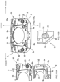
FIG. 5 is an explanatory diagram of a housing applied to the vehicle steering wheel device according to an embodiment of the present invention. -
FIG. 6 is an explanatory diagram of a locking plate applied to the vehicle steering wheel device according to an embodiment of the present invention. -
FIG. 7 is an explanatory diagram generally illustrating how to attach, via a bushing, a coil spring to the locking plate illustrated inFIG. 6 . -
FIG. 8 is an explanatory diagram of a bushing applied to the vehicle steering wheel device according to an embodiment of the present invention. -
FIG. 9 is an explanatory diagram illustrating how to attach a bushing to a locking plate in a vehicle steering wheel device according to an embodiment of the present invention. -
FIG. 10 is an explanatory diagram illustrating how to attach a bushing to a housing in a vehicle steering wheel device according to an embodiment of the present invention. -
FIG. 11 is a sectional view of the P region inFIG. 10C shown as developed. - A suitable embodiment of the vehicle steering wheel device according to the present invention is described in detail below with reference to the accompanying drawings.
-
FIG. 1 to FIG. 6 illustrate a vehicle steering wheel 1 and anairbag module 2 attached thereto. -
FIG. 1 is a perspective view generally illustrating a steering wheel 1 to which anairbag module 2 is attached.FIG. 2 is a side cross-sectional view thereof. - In the following drawings, including in
FIG. 1 , each direction is illustrated with an assumption that the steering wheel 1 mounted on the vehicle is in the neutral steering position. - The neutral steering position refers to a position where the steering angle of the steering wheel 1 is "zero" and the steered front wheels face in a straight direction.
- In the drawings, the Z axis of the three-dimensional coordinate system (hereinafter, also referred to as "Z axis direction") is an axis parallel to the rotation axis of an unillustrated steering shaft. The directions of the Z axis are: a downward direction, which is a direction, along the steering shaft, toward the front wheels; and an upward direction, which is a direction toward the steering wheel 1. In terms of the relationship with other members, the Z-axis directions are directions parallel to the axis of a
coil spring 24, which is described later. The Z-axis directions are also parallel to a direction in which thehousing 9 serving as a holding plate member and thelocking plate 8 serving as an assembling plate member are overlapped with each other. - Similarly, the directions of the X-axis of the three-dimensional coordinate system are from the 3 o'clock direction (right-hand side) to the 9 o'clock direction (left-hand side), and vise versa, of an analog clock on a plane perpendicular to the Z-axis, and the directions of the Y-axis are from the 12 o'clock direction (upside) to the 6 o'clock direction (downside), and vise versa, thereof on the same plane. In addition, the side seen from the side of the driver shall be described as the front side and the opposite side as the back side.
- The steering wheel 1 is installed on the driver's seat side of the vehicle, and is connected to the steering shaft to transmit the steering operation by the driver to the steering gear and the like.
- An
airbag module 2, which functions as a driver's seat airbag in the event of an emergency, is provided in the center of the steering wheel 1. - Under normal operation, the
airbag module 2 functions as a horn switch, which the driver presses to cause the horn to sound. - The
airbag module 2 further functions as a module damper for damping vibrations of the steering wheel 1. - The steering wheel 1 is made of a metal and is primarily composed of a
center boss section 3, arim 4 for the driver to grip, andspokes 5, which connect theboss section 3 and therim 4. To theboss section 3, the steering shaft is connected. - Now, a structure of the
airbag module 2 is described below. Theairbag module 2 on the driver side is covered with ahorn cover 6, which is made of resin and functions as a design surface. - Inside the
horn cover 6, anairbag cushion 7 is accommodated in a folded state. In the event of an emergency, theairbag cushion 7 is deployed and expanded. - As illustrated in
FIG. 3 , theairbag module 2 is composed of: ametal locking plate 8; ametal housing 9 formed in a dish shape with aperipheral wall 9a provided on the front surface side thereof and with its plate surface overlaid on the surface of thelocking plate 8; two hollowtubular damper units 10;pins 11 slidably inserted into hollow interiors of theirrespective damper units 10 and thus connecting theairbag module 2 to theboss section 3 of the steering wheel 1; acoupling member 12 provided on thehousing 9, formed in a hook shape configured to be locked by theboss section 3 of the steering wheel 1, and configured to slide in the Z-axis direction to couple theairbag module 2 with theboss section 3; aninflator 13 supplying an inflator gas to theairbag cushion 7; ametal retainer ring 15 having abolt 15a to which anut 14 is fastened to fix theairbag cushion 7, theinflator 13, and the like to thehousing 9; and thehorn cover 6, which accommodates theairbag cushion 7. - As will be described later, the
damper unit 10 is an exemplar accessory component to the steering wheel 1, and is assembled to alocking plate 8 serving as an assembling plate member. - As will be also described later, the
airbag cushion 7 is an exemplar accessory member to the steering wheel 1, and is held by ahousing 9 serving as a holding plate member. - The
damper unit 10 is a member for elastically mounting theairbag module 2 to the steering wheel 1, and forms the central portion of the module damper. - Briefly, the
damper unit 10 is configured by housing, inside aholder 17, a ring-shapedelastic body 16 for damping vibrations, and locking aninsulator plate 18 overlaid on an end of theelastic body 16 with asleeve 19, which is inserted into and retained within theelastic body 16. - Each of the
pins 11 provided in thedamper unit 10 has aflange portion 11a at an end portion thereof. Thepin 11 is inserted into thecorresponding damper unit 10 from thehousing 9 side so that theflange portion 11a abuts against thesleeve 19 of thedamper unit 10. - As illustrated in
FIG. 4 , the twodamper units 10 are arranged side by side in the X-axis directions with the neutral position of the steering wheel 1 serving as a reference, and are disposed on both the left-hand and right-hand sides of theairbag module 2. To put it differently, when the steering angle of the steering wheel 1 is set to 0, the twodamper units 10 are provided at positions in the 3 o'clock and 9 o'clock directions of the analog clock with respect to the central axis (steering shaft) of the steering wheel 1. - Each of the
pins 11 is provided so as to protrude in an Z-axis direction from thedamper unit 10 toward theboss section 3 of the steering wheel 1. - The
housing 9 and thelocking plate 8 are described below with reference toFIG. 3 ,FIG. 5A , andFIG. 6A . -
FIG. 5A is a perspective view of thehousing 9 as viewed from the back-side surface thereof, andFIG. 6A is a perspective view of thelocking plate 8 as viewed from the back side thereof. - The locking
plate 8 is provided with ahole 8a for mounting the inflator. Thehole 8a is formed through the center of thelocking plate 8. The lockingplate 8 is also provided with two recessed groove-like holding portions 20, which are formed in alignment with the arrangement of the twodamper units 10 at positions separated from thehole 8a. - A locking
hole 20a for locking and fixing theholder 17 of thedamper unit 10 is formed through each of the holdingportions 20. - An exemplar fixing structure for fixing the
damper unit 10 to thelocking hole 20a includes: the lockinghole 20a and theholder 17 each formed in an elliptical shape defined by a long axis and a short axis. Theholder 17 is inserted into thelocking hole 20a by aligning the long axis and the short axis of thelocking hole 20a with the long axis and the short axis of theholder 17, respectively. After that, theholder 17 is rotated to lock theholder 17 in thelocking hole 20a. As a result, thedamper unit 10 is assembled to thelocking plate 8. - Once the
pin 11 is inserted into thecorresponding damper unit 10, apointed head portion 11b formed at an end portion opposite to theflange portion 11a protrudes from the lockinghole 20a toward theboss section 3 of the steering wheel 1 (seeFIG. 4 ). - The
housing 9 is formed in a size capable of covering substantially theentire locking plate 8 including the holdingportions 20. - In the
housing 9, ahole portion 9b is formed in the center thereof for passing the inflator 13 therethrough. Also in thehousing 9, aperipheral wall 9a is formed at the outer edge position so as to be raised on the front side. - Once the
flange portion 11a of thepin 11 is inserted into thedamper unit 10, theflange portion 11a is held between thehousing 9 and the holdingportions 20 of thelocking plate 8. Consequently, thepin 11 and thedamper unit 10 are assembled and held between thehousing 9 and thelocking plate 8. - To assemble the
locking plate 8 with thehousing 9 with their respective plate surfaces overlaid one upon the other, anassembly protrusion 8b is formed in thelocking plate 8 and alocking bore 9c is formed in the housing so that theassembly protrusion 8b can fit in the locking bore 9c. - Furthermore, an elastically
deformable locking piece 6b formed on the tubular portion 6a of thehorn cover 6 of theairbag module 2 is locked in the locking bore 9c of thehousing 9. - Locking the locking piece 6c in the locking bore 9c attaches the
horn cover 6 accommodating theairbag cushion 7 to thehousing 9. - Further, bolt insertion bores 21 are formed in the
housing 9 and thelocking plate 8.Bolts 15a of theretainer ring 15 are inserted into and through the bolt insertion bores 21. - The
coupling member 12 provided in thehousing 9 has a joiningpart 12a joined to aperipheral wall 9a of thehousing 9 with arivet 22 at an end along a Z-axis direction, and also has ahook portion 12b locked to aboss section 3 of a steering wheel 1 at the other end. Thecoupling member 12 is formed of, for example, an elastically deformable plate-shaped metal plate or the like. - The
coupling member 12 is provided, in parallel with thedamper unit 10, between the steering wheel 1 and theairbag module 2 described above. - The
hook portion 12b is covered with a resin-madeelastic material 23 to electrically insulate theboss section 3 and thehousing 9 from each other and to provide a cushioning effect. - The
coupling member 12 has anopening 12c extending in the Z-axis directions between the joiningportion 12a and thehook portion 12b. A protruding portion (not illustrated) of theboss section 3 is inserted into theopening 12c. Theairbag module 2 is slidable in the Z-axis directions with respect to theboss section 3 by the length of theopening 12c measured in the Z-axis directions. - As illustrated in
FIG. 2 , thepins 11 and thecoupling member 12 are components for attaching theairbag module 2 to theboss section 3 of the steering wheel 1 from a Z-axis direction. - Specifically, as illustrated in
FIG. 4 , thecoupling member 12 is positioned in the lower side of the steering wheel 1 in the vertical directions (Y-axis directions) with the neutral position of the steering wheel 1 as the reference. In other words, when the steering angle of the steering wheel 1 is set to 0, thecoupling member 12 is provided at a position in the direction of 6 o'clock of the analog clock with respect to the center axis (steering shaft) of the steering wheel 1. - In a positional relation to the
damper units 10, thecoupling member 12 is arranged in the center between the twodamper units 10, at a position lower than (on the 6 o'clock side of) thesedamper units 10. - Therefore, the
damper units 10 and thecoupling member 12 are provided at their corresponding vertexes of an inverted isosceles triangle with respect to theairbag module 2. - In addition, as illustrated in
FIG. 4 , theairbag module 2 is provided with a pair of coil springs 24 on both sides of thecoupling member 12 in the X-axis directions viabushings 25. The axis of each of the coil springs 24 is parallel to the Z-axis directions. The axis of each of the coil springs 24 refers to a line passing through the center of that coil spring 24 (also referred to as the coil spring axis). - More specifically, the coil springs 24 are disposed on the back-
side surface 8c of thelocking plate 8 and are held between theboss section 3 and theairbag module 2. - The inflator 13 has an outer
peripheral flange 13a, which has bolt insertion bores 21 and abuts against the back-side surface of thelocking plate 8. - Although not illustrated, the
airbag cushion 7 has an insertion hole formed therein, into which theinflator 13 is inserted. Bolt insertion holes for inserting the bolts of theretainer ring 15 are formed around the insertion hole. - The
retainer ring 15 is provided inside theairbag cushion 7. Theretainer ring 15 has ahole 15b which communicates with thehole 9b of thehousing 9 and thehole 8a of thelocking plate 8. Thehole 15b allows theinflater 13 to be positioned in theairbag cushion 7. - The
retainer ring 15 is aligned with the insertion hole of theairbag cushion 7 so that thebolts 15a project from their respective bolt insertion bores. - Now, assembling of the airbag module is described below. The insertion hole of the
airbag cushion 7 is aligned with thehole 9b of thehousing 9, and thebolts 15a of theretainer ring 15 protruding from theairbag cushion 7 are inserted into their respective bolt insertion bores 21 of thehousing 9. - Once the
bolts 15a are inserted into their respective bolt insertion bores 21 of thehousing 9, the periphery of the insertion hole of theairbag cushion 7 is held between theretainer ring 15 and thehousing 9, and theairbag cushion 7 is installed in thehousing 9. - As a result, the
housing 9 holds theairbag cushion 7, which is an accessory member to the steering wheel 1. - On the other hand, to the
locking plate 8, thedamper units 10 are secured via theirrespective locking holes 20a after thedamper units 10 are attached inside theirrespective holding portions 20 from the front-side surface side (housing 9 side) of thelocking plate 8. - In each of the
pin 11, apointed end portion 11b is inserted into thecorresponding damper unit 10 from thehousing 9 side and protrudes out through thecorresponding locking hole 20a of thelocking plate 8. - Next, the
housing 9 is put on thelocking plate 8 from the front side, and thehousing 9 and thelocking plate 8 are overlaid one upon the other. The overlapping direction is parallel to the Z-axis directions. - The
flange portion 11a of each of thepins 11 is held between thehousing 9 and thelocking plate 8 and is retained therebetween. - The outer
peripheral flange 13a of the inflator 13 is made to abut the back-side surface 8c of thelocking plate 8. The inflator 13 is thus inserted into the insertion hole of theairbag cushion 7 through thehole 8a of thelocking plate 8, thehole 9b of thehousing 9, and thehole 15b of theretainer ring 15. - The
bolts 15a of theretainer ring 15 protruding from their respective bolt insertion bores 21 of thehousing 9 are inserted into their respective bolt insertion bores 21 of thelocking plate 8 and their respective bolt insertion bores 21 of the outerperipheral flange 13a of theinflator 13.Nuts 14 are provided on the back side of thelocking plate 8 to fasten theirrespective bolts 15a. - As a result, the
airbag cushion 7 and the inflator 13 are secured to and held by thehousing 9, and thedamper units 10, which are accessory components to the steering wheel 1, are assembled onto the lockingplate 8. - The
coupling member 12 attached to thehousing 9 is arranged in parallel with thedamper units 10 along the Z-axis directions. - Subsequently, the
horn cover 6 is attached to thehousing 9. In thehorn cover 6, thelocking piece 6b is locked in the locking bore 9c of thehousing 9. - In this way, the
airbag module 2 is assembled. - Suppose a case where the
airbag module 2 is attached to the steering wheel 1 in the Z-axis directions. In this case, as shown inFIG. 3 andFIG. 4 , coiled horn springs 26, which are elastically deformable elastic members, are provided between theboss section 3 and thelocking plate 8 so as to surround thepins 11. A pair ofcoil springs 24 are attached to each of thebushings 25 located on both sides of thecoupling member 12. - The coil springs and the horn springs 26 are made to abut the
boss section 3, and thus elastically support theairbag module 2 for the steering wheel 1. - The horn springs 26 secure a gap located between the
boss section 3 and theairbag module 2, and the gap is provided for horn operations. - When the
airbag module 2 is attached to theboss section 3, thepins 11, specifically their respectivepointed end portions 11b, are inserted into and held in their respective attachment bores (not illustrated) formed in theboss section 3, with the coil springs 24 and the horn springs 26 in an elastically compressed state. At the same time, thehook portion 12b of thecoupling member 12 is locked with theboss section 3. - The
airbag module 2 is thus attached and coupled to the steering wheel 1 in the Z-axis directions via thedamper units 10 and thecoupling member 12. - As a result, the
airbag module 2 is elastically supported, via thedamper units 10, by thehorn spring 26 relative to the steering wheel 1, with theairbag module 2 coupled to the steering wheel 1 so as to be movable (i.e., so as to be capable of being pressed) toward the steering wheel 1 (see FIG. 2B). - The
damper units 10, which are disposed between theairbag module 2 and the steering wheel 1, damp vibrations of the steering wheel 1. - The vibrations of the steering wheel 1 are transmitted to the
damper units 10 via theirrespective pins 11. The transmitted vibrations are damped by theelastic body 16 of thedamper units 10, with theairbag module 2 serving as a damper mass. - When a signal is sent from the vehicle sensors during an emergency event, the inflator gas is supplied from the inflator 13 to the
airbag cushion 7. - Once the inflation gas is supplied to the
airbag cushion 7, theairbag cushion 7 ruptures thehorn cover 6 and is expanded and deployed into the vehicle interior space to restrain the driver. - Now, a description is provided regarding the horn function. When the
airbag module 2 is pressed in the Z-axis direction toward the steering wheel 1, theentire airbag module 2 including thedamper units 10 slides against thepins 11 retained in theboss section 3, and the horn springs 26 are elastically compressed and deformed. - As a result, the contacts provided on the
airbag module 2 and on theboss section 3 are electrically connected with each other, thereby causing the horn to sound. - When pressing of the
airbag module 2 is canceled, each of the horn springs 26 is elastically restored to the original shape such that theairbag module 2 is retracted to separate the contact points from each other, thereby stopping the sounding. - Hence, the
airbag module 2 and the steering wheel 1 form a conductive circuit. - The coil springs 24, which are disposed on the back-
side surface 8c of thelocking plate 8 and held between theboss section 3 and theair bag module 2, elastically support theair bag module 2 from theboss section 3 side around thecoupling member 12 disposed on the 6 o'clock side. - The coil springs 24 ensure stable support of the
airbag module 2 when the horn is not operated, and ensures also favorable pressing operability of theairbag module 2 for the horn operation. - Specifically, the coil springs 24 elastically support, with respect to the
boss section 3, the lockingplate 8 on which thehousing 9 is overlaid. - A structure in which the coil springs 24 are attached to the
airbag module 2 using thebushings 25 will be described in detail with reference toFIG. 5 to FIG. 11 . -
FIG. 7 illustrates how thecoil spring 24 is attached to thelocking plate 8 via abushing 25. -
FIG. 5B is an enlarged view of a main part of thehousing 9, andFIG. 6B is an enlarged view of a main part of thelocking plate 8. -
FIGS. 8A to 8E are a perspective view, a front view, a top view, a bottom view, and a side view of thebushing 25, respectively. -
FIG. 9 is an explanatory diagram for describing how to attach thebushing 25 to thelocking plate 8.FIG. 9A is a perspective view illustrating how to assemble thebushing 25 to thelocking plate 8.FIG. 9B is an explanatory diagram for describing how to lock thebushing 25 by means of a first locking means.FIG. 9C is an explanatory diagram for describing the motion while thebushing 25 is being locked by the first locking means.FIG. 9D is an explanatory diagram for describing the state in which thebushing 25 is locked by means of the first locking means.FIG. 9E is a perspective view illustrating the state in which thebushing 25 is fixed to thelocking plate 8. -
FIG. 10 is an explanatory diagram for describing how to attach thebushing 25 to thehousing 9.FIG. 10A is a perspective view illustrating how to assemble thebushing 25 to thehousing 9.FIG. 10B is an explanatory diagram for describing a state in which thebushing 25 is locked by means of a second locking means.FIG. 10C is a perspective view illustrating a state in which thebushing 25 is fixed to thehousing 9. -
FIG. 11 is a sectional view of the P region inFIG. 10C shown as developed. - The
bushing 25 is inserted into both thelocking plate 8 and thehousing 9 to secure the coil springs 24 to theairbag module 2. - The
bushing 25 according to the present embodiment is formed of a synthetic resin material in a substantially hollow tubular shape. - As illustrated in
FIG. 8 , thebushing 25 includes: aspring holding portion 25a provided on one side (boss section 3 side) along the Z-axis direction; and an anchoringportion 25b provided on the other side (airbag module 2 side) therealong. - One end portion, in the longitudinal direction, of the
coil spring 24 is held by thespring holding portion 25a, whereby thecoil spring 24 is attached to and fixed to the bushing 25 (seeFIG. 7 ). - The
bushing 25 is fixed by the anchoringportion 25b, which is locked to thelocking plate 8 by means of the first locking means and which is locked to thehousing 9 by means of the second locking means. Thebushing 25 is attached to theair bag module 2 by means of the fixing accomplished by the double locking. - The double locking of the
bushing 25 means that firstly thebushing 25 by itself is locked to thelocking plate 8 by means of the first locking means and secondly thebushing 25 having been attached to thelocking plate 8 is locked together with the lockingplate 8 to thehousing 9 by means of the second locking means. - The first locking means and the second locking means may have any configurations as long as they individually lock the
bushing 25 to thelocking plate 8 and thehousing 9, respectively, so as to stop or suppress the motion of thebushing 25. - In the present embodiment, the first locking means is composed of the
bushing 25 and thelocking plate 8. - As illustrated in
FIG. 6B , a first through-hole 27 is formed in thelocking plate 8. Thebushing 25 is inserted through the first through-hole 27, so as to be rotatable about thebushing 25, that is, around the Z-axis thereof. - The size of the first through-
hole 27 is set such that the anchoringportion 25b of thebushing 25 can be inserted through the first through-hole 27. - As illustrated in
FIG. 8 , a plurality ofhooks 29 are formed on the anchoringportion 25b of thebushing 25. Thehooks 29, which are elastically bendable, are formed at intervals around thebushing 25. - In the illustrated example, two
hooks 29 are formed at 180° intervals from each other. Each of thehooks 29 is formed in an L-shape, in which abase end 29a is connected to thebushing 25. - When the
bushing 25 is inserted through the first through-hole 27, thehook 29 is disposed so that the L-shapedfree end 29b faces thehole edge 27a of the first through-hole 27 (seeFIG. 9C ). Thehook 29 is elastically bent toward the hollow inside of thebushing 25. - As illustrated in
FIG. 6B , apressing collar portion 30 is formed in the first through-hole 27. Thepressing collar portion 30 protrudes toward the inside of the first through-hole 27. - Hence, the size of the first through-
hole 27 is narrowed by thepressing collar portion 30. In the illustrated example, twopressing collar portions 30 are provided for twohooks 29. - When the
bushing 25 is rotated as illustrated inFIG. 9B , thehook 29 is moved along thehole edge 27a of the first through-hole 27 by the rotation. As a result, thepressing collar portion 30 elastically bends thehook 29, as illustrated inFIG. 9C . - In the
bushing 25, a pair of engaging portions are formed that avoid thehook 29. The pair of engaging portions are configured to engage with thepressing collar portion 30 from both the front side and the back side. - To be more specific, as illustrated in
FIG. 8 , with reference to the position of thefree end 29b of thehook 29, a first engagingportion 31 engaging with the back-side surface of thepressing collar portion 30 is formed to protrude outward in an arc shape on the side of thespring holding portion 25a, and a second engaging portion engaging with the front-side surface of thepressing collar portion 30 is formed to protrude outward in a projection shape on the opposite side so as to be positioned between the first engagingportions 31 and to overlap with thehook 29 with a clearance in the Z-axis direction from thehook 29. - In the present embodiment, the second engaging portion also serves as the stopper projection 32 (hereinafter, the second engaging portion is referred to as a stopper projection).
- In the illustrated example, two first engaging
portions 31 and twostopper projections 32 are provided so as to correspond to the twopressing collar portions 30. - In the drawing, the
reference numerals 28 are protruding portions to each of which a jig is attached to rotate and move the bushing 25 (see arrows R inFIG. 9B ). - When the
hook 29 is elastically bent by thepressing collar portion 30 upon the rotation of thebushing 25, the first engagingportion 31 and thestopper projection 32 are slidably moved with respect to thepressing collar portion 30 by the rotation of thebushing 25 while being engaged with thepressing collar portion 30 from both the front side and the back side. - As illustrated in
FIG. 6B , agroove portion 33 is formed by a partial cutout in thepressing collar portion 30. Thehook 29 enters thegroove portion 33. - As illustrated in
FIG. 9D , thehook 29, which has been rotated in an elastically bent state by thepressing collar portion 30, which protrudes toward the inside of the first through-hole 27, is elastically restored by thegroove portion 33. - In addition, the
groove portion 33 locks the elastically restoredhook 29 in the circumferential direction of the first through-hole 27 to prevent the rotation of thebushing 25. - When the
hook 29 is locked in thegroove portion 33, thebushing 25 is supported against the lockingplate 8 by the first engagingportion 31 and thestopper projection 32 which are engaged with thepressing collar portion 30 from the front side and back side, respectively. - The
hook 29 is locked with thepressing collar portion 30 provided in the first through-hole 27. In addition, the pair of the first engagingportion 31 and thestopper projection 32 are engaged with thepressing collar portion 30. As illustrated inFIG. 9E , thebushing 25 is locked and fixed, by the first locking means, to thelocking plate 8 in a state where thespring holding portion 25a protrudes from the lockingplate 8 toward theboss section 3. - As illustrated in
FIG. 9A , thebushing 25 is attached from the back-side surface 8c of thelocking plate 8. - During the attachment, the anchoring
portion 25b including thehook 29 and thestopper projection 32 is inserted into the first through-hole 27 so as to avoid thepressing collar portion 30, and then thebushing 25 is rotated to a position where thehook 29 is locked in thegroove portion 33. - In the present embodiment, the second locking means is composed of a
stopper projection 32 formed on the anchoringportion 25b of thebushing 25 and a second through-hole 34 formed in thehousing 9. - As described above, the
stopper projection 32 is also used as the second engaging portion that is configured to engage with thepressing collar portion 30. - As illustrated in
FIG. 5B , a second through-hole 34 is formed in thehousing 9, through which thebushing 25 is inserted. - The above-described first through-
hole 27 is formed to have a size that allows thestopper projection 32 to pass therethrough in order to position thestopper projection 32 with respect to thehole edge 34a of the second through-hole 34 by inserting thebushing 25 from the back-side surface 8c side of thelocking plate 6. - The second through-
hole 34 is set to be slightly larger than the first through-hole 27 with a margin. - As illustrated in
FIG. 5B , alocking collar portion 35 is formed in the second through-hole 34 so as to protrude toward the inside of the second through-hole 34. - As illustrated in
FIG. 10B , when thebushing 25 is fitted into the second through-hole 34, thelocking collar portion 35 locks thestopper projection 32 in the form of a projection located on thehole edge 34a of the second through-hole 34 to suppress the rotation of thebushing 25 in the directions of rotation of thebushing 25 about the Z-axis. - In the illustrated example, two locking
collar portions 35 are formed so as to correspond to the twostopper projections 32. - These locking
collar portions 35 press and lock the twostopper projections 32 from both sides of thebushing 25 so as to prevent thestopper projections 32 from rotating around thebushing 25 with respect to the second through-hole 34. - As illustrated in
FIG. 10A , the lockingplate 8 to which thebushing 25 is fixed is attached from the back-side surface 9d of thehousing 9. - The second locking means prevents, from rotating on the
housing 9 side, thebushing 25 locked and fixed at a predetermined rotational position with respect to thelocking plate 8 by the first locking means. - The
bushing 25 is doubly locked and fixed by the second locking means for locking thestopper projection 32 with thelocking collar portion 35 provided in the second through-hole 34, and by thehousing 9 overlaid on thelocking plate 8 as shown inFIG. 10C . -
FIG. 11 illustrates thebushing 25 in a state doubly locked by the lockingplate 8 and thehousing 9. - The first locking means locks and fixes the
bushing 25 to thelocking plate 8 by making the pressing collar portion 30 (groove portion 33) of the first through-hole 27 lock thehook 29 and by making thepressing collar portion 30 with the first engagingportion 31 and thestopper projection 32. The second locking means locks and fixes thebushing 25 to thehousing 9 by making thelocking collar portion 35 of the second through-hole 34 lock thestopper projection 32 of thebushing 25. In this way, thebushing 25 is doubly locked. - In the present embodiment, the engagement of the
bushing 25 with thepressing collar portion 30 and the locking of thebushing 25 by thelocking collar portion 35 are ensured only by thestopper projection 32. - However, it is needless to say that the engagement with the
pressing collar portion 30 and the locking by thelocking collar portion 35 may be secured at different portions formed on thebushing 25. - In the vehicle steering wheel device according to the present embodiment, the
bushing 25 is provided between the steering wheel 1 as a vibration transmission path and theairbag module 2 including theairbag cushion 7 as an accessory member and thedamper unit 10 as an accessory component. In addition, thebushing 25 fixes the coil springs 24 to theairbag module 2. The coil springs 24 are elastically bent by the horn operation and receive the reaction force accompanying the deployment and expansion actions when the airbag is actuated. Thebushing 25 is doubly locked and fixed to theairbag module 2 by means of the first locking means and the second locking means. - As a result, it is possible to prevent the
coil spring 24 from being loosened or from rattling at the fixing portion of thecoil spring 24 to theairbag module 2, thereby remarkably improving the durability and firmly attaching theairbag module 2 to the steering wheel 1. - The first locking means includes a
pressing collar portion 30 in the first through-hole 27 of thelocking plate 8 and thepressing collar portion 30 has agroove portion 33. The first locking means also includes ahook 29 and a pair of engaging portions (a first engagingportion 31 and a stopper projection 32) in thebushing 25. Thehook 29 is locked in thegroove portion 33 of thepressing collar portion 30 to prevent rotation of thebushing 25. In addition, thepressing collar portion 30 is engaged with a pair of engaging portions. In this way, thebushing 25 is supported by the lockingplate 8. - The first locking means has a simple structure and can securely lock and fix the
bushing 25 to thelocking plate 8. - The second locking means is provided with a
locking collar portion 35 in a second through-hole 34 of thehousing 9 and is also provided with astopper projection 32 in thebushing 25. While thebushing 25 is in a state of being locked and fixed to thelocking plate 8 by means of the first locking means, the second locking means suppresses the rotation of thebushing 25 by the locking of thestopper projection 32 with thelocking collar portion 35. - The second locking means also has an extremely simple structure and cooperates with the first locking means to securely lock and fix the
bushing 25 to thehousing 8. - Further, a strong and robust fixing structure of the
bushing 25 can be secured in such a narrow space as that of about the plate thickness of thehousing 9 and thelocking plate 8. - The vehicle steering wheel device described above is a preferred example of the present invention, and other exemplar embodiments can also be implemented or carried out by various methods. In particular, unless otherwise described in the specification of the application, the invention is not restricted to the shapes, sizes, configuration, arrangements, and the like of the parts illustrated in detail in the accompanying drawings. In addition, the expressions and terms used in the specification of the application are used for providing a description, without limiting the invention thereto, unless specifically described otherwise.
- For example, although two
damper units 10 are provided in the directions of 3 o'clock and 9 o'clock of the analog clock as an example of thedamper units 10 as the accessory components, the present invention is not limited to such an example. For example, in addition to these, anotherdamper unit 10 may be provided in the 12 o'clock direction of the analog clock, or asingle damper unit 10 may be provided only in the 12 o'clock direction of the analog clock. To put it differently, one or more accessory components may be provided. - A vehicle steering wheel device according to an aspect of the present invention comprises: a holding plate configured to hold an accessory member to a steering wheel 1 of a vehicle; an assembling plate member which is provided so as to be overlaid on the holding plate member and to which an accessory component to the steering wheel 1 is assembled; a
coil spring 24 elastically supporting, on the steering wheel 1, the assembling plate member on which the holding plate member is overlaid; and abushing 25 inserted through both of the holding plate member and the assembling plate member to fix thecoil spring 24, wherein thebushing 25 is locked and fixed to the assembling plate member by means of a first locking means, and wherein thebushing 25 fixed to the assembling plate member by means of the first locking means is locked and fixed to the holding plate member by means of a second locking means. - The steering wheel device according to the addendum 1 may be characterized in that the first locking means includes: a first through-
hole 27 which is formed around thebushing 25 in the assembling plate and through which thebushing 25 is inserted so as to be rotatable about thebushing 25; a plurality ofhooks 29 formed at intervals in thebushing 25 so as to be elastically bendable around thebushing 25; a pressing collar portion which is formed in the first through-hole toward an inner side of the first through-hole and which elastically bends thehooks 29 moved by the rotation of thebushing 25; a pair of engaging portions formed on the bushing and configured to be engaged with thepressing collar portion 30 from both a front side and a back side by the rotation of thebushing 25 so as to support thebushing 25 on the assembling plate member; and agroove portion 33 formed in thepressing collar portion 30 and configured to elastically restore thehook 29 moved by the rotation of thebushing 25 and to lock thehook 29 so as to prevent the rotation of thebushing 25. - The steering wheel device according to the
addendum 1 or 2 may be characterized in that, the second locking means may include: a second through-hole 34 which is formed in the holding plate member and through which thebushing 25 locked and fixed to the assembling plate member by the first locking means is inserted; and astopper projection 32 formed on thebushing 25 outward from thebushing 25, and in that the second through-hole 34 has alocking collar portion 35 formed toward the inside of the second through-hole 34 and locking thestopper projection 32 so as to suppress the rotation of thebushing 25. - In the vehicle steering wheel device according to the addendum 1 to 3, the one or more accessory components may be provided at positions in a 3 o'clock direction and in a 9 o'clock direction of the assembling plate member when a steering angle of the steering wheel is 0.
- In the steering wheel device according to the addendum 1 to 4, the one or more accessory components may be the
damper units 10. - The steering wheel device according to the addendum 1 to 5 may further comprise a
coupling member 12 that couples the holding plate member to the steering wheel 1, and thecoupling member 12 may be provided at a position in the 6 o'clock direction of the steering wheel 1 when the steering angle of the steering wheel 1 is 0. - In the steering wheel device according to the
addendum 6, thecoupling member 12 may couple the holding plate member to the steering wheel so as to be slidable in a direction parallel to an axis of thecoil spring 24. -
- 1. Steering wheel
- 7. Airbag cushion
- 8. Locking plate
- 8c. Back-side surface of locking plate
- 9. Housing
- 9d. Back-side surface of housing
- 10. Damper unit
- 24. Coil spring
- 25. Bushing
- 27. First through-hole
- 29. Hook
- 30. Pressing collar portion
- 31. First engagement portion
- 32. Stopper projection
- 33. Groove portion
- 34. Second through-hole
- 35. Locking collar portion
Claims (7)
- A vehicle steering wheel device comprising:a holding plate member configured to hold an accessory member to a steering wheel of a vehicle;an assembling plate member which is provided so as to be overlaid on the holding plate member and to which one or more accessory components to the steering wheel are assembled;a coil spring elastically supporting, on the steering wheel, the assembling plate member on which the holding plate member is overlaid; anda bushing inserted through both of the holding plate member and the assembling plate member to fix the coil spring,wherein the bushing is locked and fixed to the assembling plate member by means of a first locking means, andwherein the bushing fixed to the assembling plate member by means of the first locking means is locked and fixed to the holding plate member by means of a second locking means.
- The vehicle steering wheel device according to claim 1, wherein the first locking means includes:a first through-hole which is formed in the assembling plate member and through which the bushing is inserted so as to be rotatable about the bushing;a plurality of hooks formed on the bushing at intervals around the bushing so as to be elastically bendable;a pressing collar portion formed in the first through-hole toward an inside of the first through-hole and configured to elastically bend the hook moved by a rotation of the bushing; anda pair of engaging portions formed on the bushing and configured to be engaged with the pressing collar portion from both a front side and a back side by the rotation of the bushing so as to support the bushing on the assembling plate member; anda groove portion formed in the pressing collar portion and configured to elastically restore the hook moved by the rotation of the bushing and to lock the hook so as to prevent the rotation of the bush.
- The vehicle steering wheel device according to claim 1 or 2, wherein the second locking means includes:a second through-hole which is formed in the holding plate member and through which the bushing locked and fixed to the assembling plate member by the first locking means is inserted; anda stopper protrusion formed on the bushing so as to extend outward from the bushing,wherein the second through-hole has a locking collar portion which is formed toward an inside of the second through-hole and which locks the stopper projection so as to suppress a rotation of the bushing.
- The vehicle steering wheel device according to claim 1 or 2, wherein the one or more accessory components are provided at positions in a 3 o'clock direction and a 9 o'clock direction of the assembling plate member when a steering angle of the steering wheel is 0.
- The vehicle steering wheel device according to claim 4, wherein the one or more accessory components are damper units.
- The vehicle steering wheel device according to claim 1 or 2, further comprising: a coupling member configured to couple the holding plate member to the steering wheel,
wherein the coupling member is provided at a position in a 6 o'clock direction of the steering wheel when a steering angle of the steering wheel is 0. - The vehicle steering wheel device according to claim 6, wherein the coupling member couples the holding plate member to the steering wheel so as to be slidable in a direction parallel to an axis of the coil spring.
Applications Claiming Priority (2)
| Application Number | Priority Date | Filing Date | Title |
|---|---|---|---|
| JP2022143824 | 2022-09-09 | ||
| PCT/JP2023/030429 WO2024053404A1 (en) | 2022-09-09 | 2023-08-24 | Vehicle steering wheel device |
Publications (1)
| Publication Number | Publication Date |
|---|---|
| EP4566914A1 true EP4566914A1 (en) | 2025-06-11 |
Family
ID=90191088
Family Applications (1)
| Application Number | Title | Priority Date | Filing Date |
|---|---|---|---|
| EP23862943.0A Pending EP4566914A1 (en) | 2022-09-09 | 2023-08-24 | Vehicle steering wheel device |
Country Status (5)
| Country | Link |
|---|---|
| US (1) | US20260138663A1 (en) |
| EP (1) | EP4566914A1 (en) |
| JP (1) | JP7747905B2 (en) |
| CN (1) | CN119744238A (en) |
| WO (1) | WO2024053404A1 (en) |
Family Cites Families (6)
| Publication number | Priority date | Publication date | Assignee | Title |
|---|---|---|---|---|
| JP2011025916A (en) * | 2009-06-26 | 2011-02-10 | Autoliv Development Ab | Inflator structure of airbag for vehicle, airbag module and airbag structure |
| JP5758136B2 (en) * | 2011-01-31 | 2015-08-05 | 本田技研工業株式会社 | handle |
| JP5989449B2 (en) * | 2012-08-06 | 2016-09-07 | タカタ株式会社 | Steering wheel |
| JP2017159696A (en) * | 2016-03-07 | 2017-09-14 | タカタ株式会社 | Airbag module damper unit and steering wheel |
| JP6874566B2 (en) | 2017-06-28 | 2021-05-19 | Joyson Safety Systems Japan株式会社 | Steering wheel |
| CN116056968A (en) * | 2020-08-28 | 2023-05-02 | 奥托立夫开发公司 | Steering wheel device for vehicle |
-
2023
- 2023-08-24 CN CN202380060918.2A patent/CN119744238A/en active Pending
- 2023-08-24 JP JP2024545557A patent/JP7747905B2/en active Active
- 2023-08-24 WO PCT/JP2023/030429 patent/WO2024053404A1/en not_active Ceased
- 2023-08-24 EP EP23862943.0A patent/EP4566914A1/en active Pending
- 2023-08-24 US US19/109,863 patent/US20260138663A1/en active Pending
Also Published As
| Publication number | Publication date |
|---|---|
| JPWO2024053404A1 (en) | 2024-03-14 |
| US20260138663A1 (en) | 2026-05-21 |
| WO2024053404A1 (en) | 2024-03-14 |
| JP7747905B2 (en) | 2025-10-01 |
| CN119744238A (en) | 2025-04-01 |
Similar Documents
| Publication | Publication Date | Title |
|---|---|---|
| EP3812240B1 (en) | Structure for mounting and fixing damper unit in steering wheel, and steering wheel | |
| US11034374B2 (en) | Steering wheel | |
| US11305716B2 (en) | Steering wheel | |
| US20200017057A1 (en) | Damper mechanism of steering wheel and steering wheel apparatus for vehicle | |
| US11529921B2 (en) | Steering wheel | |
| CN114845926B (en) | Steering wheel device for vehicle | |
| US12109963B2 (en) | Steering wheel | |
| CN111003053A (en) | Assembly of a driver airbag module and a steering wheel | |
| US20260138663A1 (en) | Vehicle steering wheel device | |
| JPH06191413A (en) | Steering wheel | |
| EP4559780A1 (en) | Structure for attaching airbag module to steering wheel | |
| US12194939B2 (en) | Driver seat airbag device | |
| US20240227716A1 (en) | Steering wheel | |
| JP7286218B2 (en) | Fixing structure for damper unit in steering wheel and steering wheel device for vehicle | |
| JP2017088115A (en) | Automobile component | |
| JP7846766B2 (en) | Airbag system installed in the steering wheel |
Legal Events
| Date | Code | Title | Description |
|---|---|---|---|
| STAA | Information on the status of an ep patent application or granted ep patent |
Free format text: STATUS: THE INTERNATIONAL PUBLICATION HAS BEEN MADE |
|
| PUAI | Public reference made under article 153(3) epc to a published international application that has entered the european phase |
Free format text: ORIGINAL CODE: 0009012 |
|
| STAA | Information on the status of an ep patent application or granted ep patent |
Free format text: STATUS: REQUEST FOR EXAMINATION WAS MADE |
|
| 17P | Request for examination filed |
Effective date: 20250307 |
|
| AK | Designated contracting states |
Kind code of ref document: A1 Designated state(s): AL AT BE BG CH CY CZ DE DK EE ES FI FR GB GR HR HU IE IS IT LI LT LU LV MC ME MK MT NL NO PL PT RO RS SE SI SK SM TR |
|
| DAV | Request for validation of the european patent (deleted) | ||
| DAX | Request for extension of the european patent (deleted) |