EP4566823A1 - Pressure measurement device and recording device provided with same - Google Patents
Pressure measurement device and recording device provided with same Download PDFInfo
- Publication number
- EP4566823A1 EP4566823A1 EP23865387.7A EP23865387A EP4566823A1 EP 4566823 A1 EP4566823 A1 EP 4566823A1 EP 23865387 A EP23865387 A EP 23865387A EP 4566823 A1 EP4566823 A1 EP 4566823A1
- Authority
- EP
- European Patent Office
- Prior art keywords
- pressure
- tank
- supply
- recovery
- ink
- Prior art date
- Legal status (The legal status is an assumption and is not a legal conclusion. Google has not performed a legal analysis and makes no representation as to the accuracy of the status listed.)
- Pending
Links
Images




Classifications
-
- B—PERFORMING OPERATIONS; TRANSPORTING
- B41—PRINTING; LINING MACHINES; TYPEWRITERS; STAMPS
- B41J—TYPEWRITERS; SELECTIVE PRINTING MECHANISMS, i.e. MECHANISMS PRINTING OTHERWISE THAN FROM A FORME; CORRECTION OF TYPOGRAPHICAL ERRORS
- B41J2/00—Typewriters or selective printing mechanisms characterised by the printing or marking process for which they are designed
- B41J2/005—Typewriters or selective printing mechanisms characterised by the printing or marking process for which they are designed characterised by bringing liquid or particles selectively into contact with a printing material
- B41J2/01—Ink jet
- B41J2/17—Ink jet characterised by ink handling
- B41J2/18—Ink recirculation systems
-
- B—PERFORMING OPERATIONS; TRANSPORTING
- B41—PRINTING; LINING MACHINES; TYPEWRITERS; STAMPS
- B41J—TYPEWRITERS; SELECTIVE PRINTING MECHANISMS, i.e. MECHANISMS PRINTING OTHERWISE THAN FROM A FORME; CORRECTION OF TYPOGRAPHICAL ERRORS
- B41J2/00—Typewriters or selective printing mechanisms characterised by the printing or marking process for which they are designed
- B41J2/005—Typewriters or selective printing mechanisms characterised by the printing or marking process for which they are designed characterised by bringing liquid or particles selectively into contact with a printing material
- B41J2/01—Ink jet
- B41J2/17—Ink jet characterised by ink handling
- B41J2/175—Ink supply systems ; Circuit parts therefor
- B41J2/17503—Ink cartridges
- B41J2/17556—Means for regulating the pressure in the cartridge
-
- B—PERFORMING OPERATIONS; TRANSPORTING
- B41—PRINTING; LINING MACHINES; TYPEWRITERS; STAMPS
- B41J—TYPEWRITERS; SELECTIVE PRINTING MECHANISMS, i.e. MECHANISMS PRINTING OTHERWISE THAN FROM A FORME; CORRECTION OF TYPOGRAPHICAL ERRORS
- B41J2/00—Typewriters or selective printing mechanisms characterised by the printing or marking process for which they are designed
- B41J2/005—Typewriters or selective printing mechanisms characterised by the printing or marking process for which they are designed characterised by bringing liquid or particles selectively into contact with a printing material
- B41J2/01—Ink jet
- B41J2/17—Ink jet characterised by ink handling
- B41J2/175—Ink supply systems ; Circuit parts therefor
- B41J2/17566—Ink level or ink residue control
-
- B—PERFORMING OPERATIONS; TRANSPORTING
- B41—PRINTING; LINING MACHINES; TYPEWRITERS; STAMPS
- B41J—TYPEWRITERS; SELECTIVE PRINTING MECHANISMS, i.e. MECHANISMS PRINTING OTHERWISE THAN FROM A FORME; CORRECTION OF TYPOGRAPHICAL ERRORS
- B41J2/00—Typewriters or selective printing mechanisms characterised by the printing or marking process for which they are designed
- B41J2/005—Typewriters or selective printing mechanisms characterised by the printing or marking process for which they are designed characterised by bringing liquid or particles selectively into contact with a printing material
- B41J2/01—Ink jet
- B41J2/17—Ink jet characterised by ink handling
- B41J2/175—Ink supply systems ; Circuit parts therefor
- B41J2/17566—Ink level or ink residue control
- B41J2002/17579—Measuring electrical impedance for ink level indication
Definitions
- the present disclosure relates to a pressure measurement apparatus and a recording apparatus provided with the same.
- Patent Document 1 discloses a recording apparatus including a liquid ejection mechanism for forming an image by ejecting liquid onto a recording medium.
- the liquid ejection mechanism includes a liquid ejection head, a moving table supporting the liquid ejection head and movable in the main scanning direction, and a pressure measurement apparatus arranged on the moving table.
- the pressure measurement apparatus measures the pressure of the liquid inside the liquid ejection head, and includes a pressure transmission path communicating with the liquid ejection head, and a pressure sensor capable of measuring the pressure of the pressure transmission pipe.
- Patent Document 1 JP 2010-52357 A
- a pressure measurement apparatus is a pressure measurement apparatus for measuring a pressure in a plurality of pressure transmission paths that apply pressure to an object via a gas.
- the apparatus includes at least one pressure measurement section including a measurement path with an internal space configured to receive the gas, and a pressure sensor configured to detect the pressure in the internal space, and at least one switching section configured to selectively switch a connection destination of the measurement path from among the plurality of pressure transmission paths.
- a recording apparatus includes the pressure measurement apparatus described above, the plurality of pressure transmission paths, and at least one liquid ejection section configured to eject a liquid onto a recording material.
- Each of the plurality of pressure transmission paths is configured to apply the pressure to the liquid that is supplied to or recovered from the at least one liquid ejection section.
- a pressure measurement apparatus and a recording apparatus will be described below with reference to the drawings.
- the following embodiments will exemplify an ink jet printer as a specific example of a recording apparatus, equipped with an ink head to eject ink for image formation on a wide and long recording medium.
- the ink jet printer is suitable for digital textile printing in which images such as letters and patterns are printed on a recording medium made of fabric such as textile or knitted fabric by an inkjet method.
- the recording apparatus according to the present disclosure can also be used for printing various images on a recording medium such as a paper sheet or a resin sheet.
- FIG. 1 is a perspective view illustrating the overall configuration of an ink jet printer 1 according to a first embodiment of the present disclosure.
- FIG. 2 is a schematic cross-sectional view of a line II-II in FIG. 1 .
- the ink jet printer 1 is a printer that prints images on a wide and long workpiece W (recording medium) by an inkjet method, and includes an apparatus frame 10, a workpiece conveyance section 20 (conveyance section) and a carriage 3 incorporated in the apparatus frame 10.
- the left-right direction is a main scanning direction S for printing the workpiece W ( FIG. 3 )
- a rearward to forward direction is a sub scanning direction (conveyance direction F of the workpiece W, which is a direction intersecting the main scanning direction S).
- the apparatus frame 10 forms a framework for mounting various components of the ink jet printer 1.
- the workpiece conveyance section 20 is a mechanism for intermittently feeding (conveying) the workpiece W so as to advance in the conveyance direction F from the rearward to forward direction in a printing area where the inkjet printing process is performed.
- An ink head 4, a pre-treatment liquid head 5, a post-treatment liquid head 6, and a sub-tank 7 are mounted on the carriage 3, and the carriage 3 reciprocates in the main scanning direction S (left-right direction) crossing the conveyance direction F of the workpiece W during an inkjet printing process.
- the apparatus frame 10 includes a central frame 111, a right frame 112, and a left frame 113.
- the central frame 111 forms a framework for mounting the various components of the ink jet printer 1, and has a left-right width corresponding to the workpiece conveyance section 20.
- the right frame 112 and the left frame 113 are erected to the right and left of the central frame 111, respectively.
- the space between the right frame 112 and the left frame 113 is the printing area 12 where the printing process is executed for the workpiece W.
- the right frame 112 forms a maintenance area 13.
- the maintenance area 13 is an area where the carriage 3 is retracted when the printing process is not executed.
- the nozzles (discharge holes) of the ink head 4, pre-treatment liquid head 5 and post-treatment liquid head 6 are cleaned and purged, and the caps are fitted.
- the left frame 113 forms a return area 14 of the carriage 3.
- the return area 14 is an area where the carriage 3, which has mainly scanned the printing area 12 from the right to the left in the printing process, temporarily enters when performing main scanning in the reverse direction.
- a carriage guide 15 for causing the carriage 3 to reciprocate in the left-right direction, is mounted on the upper side of the apparatus frame 10.
- the carriage guide 15 is a plate shaped member that is long in the left-right direction and is arranged above the workpiece conveyance section 20.
- a timing belt 16 is attached to the carriage guide 15 so as to be movable around in the left-right direction (main scanning direction).
- the timing belt 16 is an endless belt and is driven to move around in the left direction or the right direction.
- the carriage guide 15 is equipped with a pair of upper and lower guide rails 17, which extend in parallel in the left-right direction and hold the carriage 3 so as to be capable of reciprocating in the main scanning direction S.
- the carriage 3 is engaged with the guide rails 17.
- the carriage 3 is fixed to the timing belt 16.
- the carriage 3 moves in the left or right direction along the carriage guide 15 while being guided by the guide rails 17 as the timing belt 16 moves in the left or right direction.
- the workpiece conveyance section 20 includes a feed roller 21 for delivering the workpiece W before printing and a take-up roller 22 for winding the workpiece W after printing.
- the feed roller 21 is arranged in the rearward lower portion of the apparatus frame 10 and is a winding shaft of a feed roll WA, which is a winding body of the workpiece W before printing.
- the take-up roller 22 is arranged in the front lower portion of the apparatus frame 10 and is a winding shaft of a take-up roll WB, which is the winding body of the workpiece W after the printing process.
- the take-up roller 22 is attached with a first motor M1 that rotates and drives the take-up roller 22 around the axis to execute the winding operation of the workpiece W.
- a first tension roller 23, a workpiece guide 24, a conveyance roller 25, a pinch roller 26, a return roller 27, and a second tension roller 28 are arranged in order from the upstream side.
- the first tension roller 23 applies a predetermined tension to the workpiece W upstream of the conveyance roller 25.
- the workpiece guide 24 changes the conveyance direction of the workpiece W from the upward direction to the forward direction and conveys the workpiece W into the printing area 12.
- the conveyance roller 25 is a roller that generates a conveyance force to intermittently feed the workpiece W in the printing area 12.
- the conveyance roller 25 is driven to rotate around the axis by a second motor M2 and intermittently conveys the workpiece W in the forward direction (predetermined conveyance direction F) so that the workpiece W passes through the printing area 12 (image forming position) facing the carriage 3.
- the pinch roller 26 is arranged so as to face the conveyance roller 25 from above, and forms a conveyance nip with the conveyance roller 25.
- the return roller 27 changes the conveyance direction of the workpiece W, which has passed through the printing area 12, from the forward direction to the downward direction, and guides the workpiece W after the printing process to the take-up roller 22.
- the second tension roller 28 applies a predetermined tension to the workpiece W downstream of the conveyance roller 25.
- a platen 29 is arranged below the conveyance path of the workpiece W in the printing area 12.
- the carriage 3 reciprocates in the main scanning direction S (left-right direction in the present embodiment) that intersects (orthogonal in the present embodiment) the conveyance direction F while being cantilevered by the guide rail 17.
- the carriage 3 includes a carriage frame 30 and the ink head 4, pre-treatment liquid head 5, post-treatment liquid head 6 and sub-tank 7 ( FIG. 3 ) mounted on the carriage frame 30.
- the carriage frame 30 includes a head support frame 31 and a back frame 32.
- the head support frame 31 is a horizontal plate for holding the heads 4 to 6 described above.
- the back frame 32 is a vertical plate extending upward from the rear end edge of the head support frame 31. As described above, the timing belt 16 is fixed to the back frame 32.
- the guide rails 17 are engaged with the back frame 32. That is, in the present embodiment, the back frame 32 is an engaging section held cantilevered by the guide rails 17.
- the head support frame 31 is a horizontal plate whose rear end side is cantilevered by the engaging section to the guide rails 17.
- the cantilevered state represents a state in which the engaging section (back frame 32), which is a section held by the guide rails 17 as holding members in the carriage 3, exists only on one side, upstream or downstream of the center of carriage 3 in the conveyance direction F, and no other engaging section exists on the opposite side to the side where the engaging section exists.
- the engaging section may be located outside the range where the ink head 4 and the treatment heads are located in the conveyance direction F. That is, the engaging section may be located only upstream or downstream of the range where the ink head 4 and the treatment heads are located in the conveyance direction F.
- FIG. 3 is an enlarged perspective view of the carriage 3 illustrated in FIG. 1 .
- FIG. 3 illustrates the conveyance direction F (sub scanning direction) of the workpiece W, and the main scanning direction S that is a movement direction of the carriage 3.
- FIG. 3 illustrates an example in which a plurality of ink heads 4 for ejecting ink for image formation onto the workpiece W, pre-treatment liquid heads 5 and post-treatment liquid heads 6 for ejecting non-chromatic treatment liquid, and a plurality of sub-tanks 7 for supplying the ink and treatment liquid to these heads 4 to 6 are mounted on the carriage 3.
- Each of the ink heads 4 includes a number of nozzles (ink discharge holes) for ejecting ink droplets by an ejecting method such as, for example, a piezo method using a piezo element or a thermal method using a heating element, and ink paths for guiding ink to the nozzles.
- an ejecting method such as, for example, a piezo method using a piezo element or a thermal method using a heating element
- ink paths for guiding ink to the nozzles for example, water-based pigment ink containing water-based solvent, pigment, and binder resin can be used.
- the plurality of ink heads 4 in the present embodiment can eject ink of eight colors.
- the ink heads 4 are mounted on the head support frame 31 of the carriage 3 in two rows in the main scanning direction S.
- the ink heads 4 of each color include 2 heads.
- the ink heads 4 include a first upstream ink head 41A and a first downstream ink head 41B. These ink heads 4 eject yellow ink.
- the ink heads 4 include a second upstream ink head 42A and a second downstream ink head 42B. These ink heads 4 eject magenta ink.
- two ink heads 4 for ejecting ink of the same color are arranged at mutually different positions in the conveyance direction F and the main scanning direction S. As a set of these two ink heads 4, a total of 8 sets of ink heads 4 (41A to 48A, 41B to 48B) eject ink of different colors from each other.
- the pre-treatment liquid heads 5 and the post-treatment liquid heads 6 are located in different positions from the ink heads 4 in the conveyance direction F.
- the pre-treatment liquid heads 5 are located upstream of the ink heads 4 in the conveyance direction F.
- FIG. 3 illustrates an example where one pre-treatment liquid head 5 is located near the left end of the ink head 4 array.
- the post-treatment liquid heads 6 are located downstream of the ink heads 4 in the conveyance direction F.
- FIG. 3 illustrates an example where one post-treatment liquid head 6 is located at the right end of the ink head 4 array.
- a plurality of pre-treatment liquid heads 5 or a plurality of post-treatment liquid heads 6 may be located.
- the carriage 3 includes at least one pre-treatment liquid head 5 and at least one post-treatment liquid head 6, individually, but in other embodiments, the pre-treatment liquid head 5 and post-treatment liquid head 6 need not be located.
- a series of heads along the main scanning direction S composed of the ink heads 4, pre-treatment liquid heads 5 and post-treatment liquid heads 6 is referred to as a column of heads or simply a column.
- a series of heads along the conveyance direction F composed of the ink heads 4, pre-treatment liquid heads 5 and post-treatment liquid heads 6 is referred to as a row of heads or simply a row.
- the pre-treatment liquid head 5 ejects a pre-treatment liquid for applying a predetermined pre-treatment onto the workpiece W.
- the pre-treatment liquid head 5 ejects the pre-treatment liquid from the ink head 4 onto a position of the workpiece W, to which the ink has not yet been ejected from the ink head 4.
- the pre-treatment liquid is a non-chromatic treatment liquid that does not develop color even when adhering to the workpiece W, and is, for example, a treatment liquid that exhibits a function of enhancing the fixability of ink to the workpiece W and the cohesiveness of the ink pigment.
- a treatment liquid containing a binder resin in the solvent or a treatment liquid containing a cationic resin that positively charges the solvent can be used.
- the post-treatment liquid head 6 ejects a post-treatment liquid for applying a predetermined post-treatment onto the workpiece W to which the ink has adhered.
- the post-treatment liquid head 6 ejects the post-treatment liquid onto a position of the workpiece W, to which the ink has been ejected from the ink head 4.
- the post-treatment liquid is a non-chromatic treatment liquid that does not develop color even when adhering to the workpiece W in the same way, and is a treatment liquid that exhibits a function of enhancing the fixability and robustness (resistance to rubbing and scraping) of the ink image printed on the workpiece W by the ink head 4.
- a silicone-based treatment liquid or the like can be used as such a post-treatment liquid.
- the post-treatment liquid and the pre-treatment liquid are different treatment liquids. Specifically, the post-treatment liquid and the pre-treatment liquid contain different components.
- the non-chromatic treatment liquid refers to a liquid that is not recognized by the naked eye as having a color when printed alone on a recording medium.
- color includes one having zero saturation such as black, white, or gray.
- the non-chromatic treatment liquid is basically a transparent liquid. However, for example, when one liter of the treatment liquid is viewed as a liquid, it may not be completely transparent and may appear slightly white. Such a color is extremely light and cannot be recognized by the naked eye as a color when printed alone on a recording medium.
- there may be changes such as the creation of gloss on the recording medium, but such a state is not considered to be a color.
- the pre-treatment liquid and post-treatment liquid may be ejected almost over the entire surface of the workpiece W, or may be ejected selectively according to the image to be printed in the same manner as ink.
- the pre-treatment liquid, the ink, and the post-treatment liquid are ejected in order, onto the workpiece W in the portion where colors are printed according to the image.
- the ink may be of one color or a plurality of colors.
- the pre-treatment liquid and the post-treatment liquid are not ejected onto the portion where colors are not printed, that is, the ink is not ejected.
- the selection of the ejection of the pre-treatment liquid and the post-treatment liquid may be partially different from that of the ejection of the ink.
- an opening 31H is provided at the placement position of the head of the head support frame 31.
- the ink heads 4, the pre-treatment liquid heads 5, and the post-treatment liquid heads 6 are assembled in the head support frame 31 so as to be fitted into each opening 31H.
- Each of the nozzles arranged on the lower end surfaces of the heads 4, 5, and 6 are exposed from each opening 31H.
- the plurality of sub-tanks 7 are supported by the carriage 3 on the upper side of the heads 4, 5 and 6 via the holding frame not illustrated.
- the plurality of sub-tanks 7 are each provided corresponding to each of the heads 4, 5 and 6.
- Each sub-tank 7 is supplied with ink or treatment liquid from a main tank 90 containing ink and treatment liquid, which are supplied to each of the heads 4, 5 and 6.
- Each sub-tank 7 is connected to the corresponding one of the heads 4, 5 and 6 by a pipe not illustrated in FIG. 3 .
- the plurality of sub-tanks 7 include a first supply sub-tank 71A to an eighth supply sub-tank 78A, a pre-treatment supply sub-tank 7FA, and a post-treatment supply sub-tank 7RA arranged along the main scanning direction S on the rear side.
- the plurality of sub-tanks 7 include a first recovery sub-tank 71B to an eighth recovery sub-tank 78B, a pre-treatment recovery sub-tank 7FB, and post-treatment recovery sub-tank 7RB arranged along the main scanning direction S on the front side.
- the first supply sub-tank 71A and the first recovery sub-tank 71B located on the leftmost side of the carriage 3 contain yellow ink.
- the first supply sub-tank 71A supplies yellow ink to the first upstream ink head 41A and the first downstream ink head 41B.
- the first recovery sub-tank 71B recovers the yellow ink from the first upstream ink head 41A and the first downstream ink head 41B. At this time, some yellow ink is ejected from the first upstream ink head 41A and the first downstream ink head 41B toward the workpiece W.
- a second supply sub-tank 72A supplies magenta ink to the second upstream ink head 42A and second downstream ink head 42B.
- a second recovery sub-tank 72B recovers magenta ink from the second upstream ink head 42A and second downstream ink head 42B.
- Other sub-tanks from the third sub-tank to eighth sub-tank have the same structure and function as described above.
- the pre-treatment supply sub-tank 7FA supplies the pre-treatment liquid to the pre-treatment liquid head 5, and the pre-treatment recovery sub-tank 7FB recovers pre-treatment liquid from the pre-treatment liquid head 5.
- the post-treatment supply sub-tank 7RA supplies the post-treatment liquid to the post-treatment liquid head 6, and the post-treatment recovery sub-tank 7RB recovers post-treatment liquid from the post-treatment liquid head 6.
- the ink jet printer 1 is an all-in-one printer in which three types of heads: the ink head 4; the pre-treatment liquid head 5; and the post-treatment liquid head 6, are mounted in one carriage 3.
- the pre-treatment liquid ejection step and post-treatment liquid ejection step can be integrally executed.
- the textile printing process can be simplified and the textile printing apparatus can be made compact.
- the ink jet printer 1 performs printing processing on the workpiece W by the serial printing method. Specifically, when the workpiece W has a wide size, printing cannot be performed while continuously feeding the workpiece W.
- the serial printing method is a printing method that repeats reciprocating movement of the carriage 3, on which the ink heads 4 of respective colors are mounted, in the main scanning direction S, and intermittent feeding of the workpiece W in the conveyance direction F.
- the carriage 3 moves in the forward direction, which is one of the main scanning directions S, printing of the strip shape image is performed.
- feeding of the workpiece W is stopped.
- the workpiece W is sent out in the conveyance direction F by a predetermined pitch.
- the carriage 3 waits at the return area 14 on the left end side.
- the carriage 3 turns back in the backward direction opposite the forward direction with the reverse movement of the timing belt 16.
- the workpiece W is in a stop state.
- the carriage 3 prints a next strip shape image upstream of the strip shape image.
- the same operation is repeated.
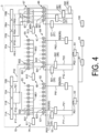
- FIG. 4 is a schematic diagram illustrating a plurality of pressure transmission paths around the carriage 3 according to the present embodiment.
- FIG. 5 is a schematic diagram illustrating the supply sub-tank and the recovery sub-tank according to the present embodiment.
- FIG. 6 is a schematic diagram illustrating a flow of ink around the liquid ejection head according to the present embodiment.
- a line connecting the members indicates a pipe (tube) through which a gas or a liquid flows.
- pressure is applied through a gas (air) to each of the first supply sub-tank 71A to the post-treatment supply sub-tank 7RA, the first recovery sub-tank 71B to the post-treatment recovery sub-tank 7RB mounted on the carriage 3 in FIG. 3 .
- a liquid (ink, pre-treatment liquid and post-treatment liquid) is supplied from each of the supply sub-tanks to the ink head 4, the pre-treatment liquid head 5, and the post-treatment liquid head 6, respectively.
- the ink jet printer 1 includes: a controller 100; a compressor 50 (gas pressure source); a filter 51; a purge main regulator 52; a first main regulator 53; a second main regulator 54; an ink supply regulator 55; an ink recovery regulator 56; a treatment liquid supply regulator 57; and a treatment liquid recovery regulator 58. These devices or members are located outside the carriage 3 in the apparatus frame 10 ( FIG. 1 ) of the ink jet printer 1.
- the controller 100 controls the operation of the ink jet printer 1 and electrically controls each member illustrated in FIG. 4 .
- the compressor 50 generates the pressure supplied to each sub-tank 7 and compresses the gas and continuously sends it out.
- the compressor 50 known reciprocating compressors and rotary compressors can be used.
- the compressor pressure is set to 500 to 800 kPa.
- the filter 51 removes foreign matter, dust, or the like, contained in the gas discharged from the compressor 50.
- the opening diameter of the filter 51 is set to 5 ⁇ m.
- the gas passed through the filter 51 flows into three flow paths: a first main pressure supply path P01; a second main pressure supply path P02; and a purge pressure supply path P03.
- the purge main regulator 52 is located downstream of the filter 51 in the gas flow and is used to adjust the pressure of the purge pressure supply path P03.
- the first main regulator 53 is located downstream of the filter 51 in the gas flow and is used to adjust the pressure of the first main pressure supply path P01.
- the second main regulator 54 is located downstream of the filter 51 in the gas flow and is used to adjust the pressure of the second main pressure supply path P02.
- the purge main regulator 52, the first main regulator 53, and the second main regulator 54 are, for example, NPN type regulators with open collector outputs. These regulators each receive a command signal from the controller 100 and open valves to adjust the pressure of each flow path to match the signal.
- the first main pressure supply path P01 is divided into eight flow paths corresponding to the first supply sub-tank 71A to the eighth supply sub-tank 78A downstream of the first main regulator 53.
- FIG. 4 illustrates a first supply side pressure supply path P11, a second supply side pressure supply path P21, and an eighth supply side pressure supply path P81, and does not illustrate the other flow paths.
- the first supply side pressure supply path P11 is a flow path extending from the first main pressure supply path P01 (first main regulator 53) to the first supply sub-tank 71A.
- the second supply side pressure supply path P21 is a flow path extending from the first main pressure supply path P01 to the second supply sub-tank 72A.
- the eighth supply side pressure supply path P81 is a flow path extending from the first main pressure supply path P01 to the eighth supply sub-tank 78A ( FIG. 3 ).
- the ink supply regulator 55 is arranged in each supply side pressure supply path and has a function of adjusting the pressure supplied to the supply sub-tank for each ink.
- the ink supply regulator 55 is composed of an electro-pneumatic regulator.
- a first ink supply regulator 551, a second ink supply regulator 552, and an eighth ink supply regulator 558 are illustrated corresponding to the first supply side pressure supply path P11, the second supply side pressure supply path P21, and the eighth supply side pressure supply path P81, and other ink supply regulators are not illustrated.
- These regulators each receive a command signal from the controller 100 and open valves to adjust the pressure of each flow path to match the signal.
- the target pressure applied by each ink supply regulator 55 to the supply sub-tank is set to 15 kPa.
- the second main pressure supply path P02 downstream of second main regulator 54, is divided into 12 flow paths corresponding to: the first recovery sub-tank 71B to the eighth recovery sub-tank 78B, and further; the pre-treatment supply sub-tank 7FA; the pre-treatment recovery sub-tank 7FB; the post-treatment supply sub-tank 7RA; and the post-treatment recovery sub-tank 7RB.
- FIG. 1 the first recovery sub-tank 71B to the eighth recovery sub-tank 78B, and further; the pre-treatment supply sub-tank 7FA; the pre-treatment recovery sub-tank 7FB; the post-treatment supply sub-tank 7RA; and the post-treatment recovery sub-tank 7RB.
- the first recovery side pressure supply path P12 is a flow path that extends from the second main pressure supply path P02 (second main regulator 54) to the first recovery sub-tank 71B.
- the second recovery side pressure supply path P22 is a flow path that extends from the second main pressure supply path P02 to the second recovery sub-tank 72B.
- the eighth recovery side pressure supply path P82 is a flow path that extends from the second main pressure supply path P02 to the eighth recovery sub-tank 78B.
- the pre-treatment liquid pressure supply path PFA is a flow path that extends from the second main pressure supply path P02 (second main regulator 54) to the pre-treatment supply sub-tank 7FA.
- the pre-treatment liquid pressure recovery path PFB is a flow path that extends from the second main pressure supply path P02 to the pre-treatment recovery sub-tank 7FB.
- the post-treatment liquid pressure supply path PRA is a flow path that extends from the second main pressure supply path P02 to the post-treatment supply sub-tank 7RA.
- the post-treatment liquid pressure recovery path PRB is a flow path that extends from the second main pressure supply path P02 to the post-treatment recovery sub-tank 7RB.
- the ink recovery regulator 56 is arranged in each recovery side pressure supply path and has a function of adjusting the pressure supplied to each ink recovery sub-tank.
- the ink recovery regulator 56 is composed of an electro-pneumatic regulator.
- FIG. 4 illustrates: a first ink recovery regulator 561; a second ink recovery regulator 562; and an eighth ink recovery regulator 568 corresponding to: the first recovery side pressure supply path P12; the second recovery side pressure supply path P22; and the eighth recovery side pressure supply path P82, and illustration of other ink recovery regulators are omitted.
- These regulators each receive a command signal from the controller 100 and open valves to adjust the pressure of each flow path to match the signal.
- the target pressure applied by each ink recovery regulator 56 to each ink recovery sub-tank is set to -20 kPa.
- the treatment liquid supply regulator 57 (pre-treatment liquid supply regulator 571, post-treatment liquid supply regulator 572) is arranged in the supply side pressure supply path of each treatment liquid.
- the treatment liquid recovery regulator 58 (pre-treatment liquid recovery regulator 581, post-treatment liquid recovery regulator 582) is arranged in the recovery side pressure supply path of each treatment liquid.
- These regulators have the same structure and function as the ink supply regulators 55 and the ink recovery regulators 56.
- the target pressure applied by the treatment liquid supply regulator 57 and the treatment liquid recovery regulator 58 to each treatment liquid sub-tank is set to -5 kPa.
- the ink jet printer 1 further includes: a first pressure measurement section 1A; a second pressure measurement section 1B; a third pressure measurement section 1C; an ink supply purge valve 62; an ink supply measurement valve 63; an ink recovery purge valve 64; an ink recovery measurement valve 65; a treatment liquid purge valve 66; and a treatment liquid measurement valve 67, which are disposed on the carriage 3.
- the first pressure measurement section 1A includes a first pressure sensor 611 and a first pressure measurement path M01.
- the second pressure measurement section 1B includes a second pressure sensor 612 and a second pressure measurement path M02.
- the third pressure measurement section 1C includes a third pressure sensor 613 and a third pressure measurement path M03.
- the first pressure sensor 611 measures the pressure of the first pressure measurement path M01, and inputs a signal corresponding to the measurement result to the controller 100.
- the second pressure sensor 612 measures the pressure of the second pressure measurement path M02, and inputs a signal corresponding to the measurement result to the controller 100.
- the third pressure sensor 613 measures the pressure of the third pressure measurement path M03, and inputs a signal corresponding to the measurement result to the controller 100.
- the first pressure measurement path M01 can communicate with any of the supply paths from the first supply side pressure supply path P11 to the eighth supply side pressure supply path P81 according to the opening and closing of the ink supply measurement valve 63.
- the second pressure measurement path M02 can communicate with any of the supply paths from the first recovery side pressure supply path P12 to the eighth recovery side pressure supply path P82 according to the opening and closing of the ink recovery measurement valve 65.
- the third pressure measurement path M03 can communicate with any of the supply paths from the pre-treatment liquid pressure supply path PFA, the pre-treatment liquid pressure recovery path PFB, the post-treatment liquid pressure supply path PRA, and the post-treatment liquid pressure recovery path PRB according to the opening and closing of the treatment liquid measurement valve 67.
- the ink supply purge valve 62 includes eight valves for connecting the purge pressure supply path P03 to any one of the first supply side pressure supply path P11 to the eighth supply side pressure supply path P81. As illustrated in FIG. 4 , the ink supply purge valve 62 includes: a first ink supply purge valve 621 located in the first supply side pressure supply path P11; and a second ink supply purge valve 622 located at the second supply side pressure supply path P21. Each of these valves is composed of a known three-port solenoid valve. In the present embodiment, along with the ink recovery purge valve 64 and the treatment liquid purge valve 66, a total of 20 three-port solenoid valves are arranged in a single valve section as a 20-unit three-port solenoid valve assembly.
- the ink supply measurement valve 63 includes eight valves for connecting the first pressure measurement path M01 to one of the first supply side pressure supply path P11 to the eighth supply side pressure supply path P81, as described above. As illustrated in FIG. 4 , the ink supply measurement valve 63 includes a first ink supply measurement valve 631 connected to the first supply side pressure supply path P11 and a second ink supply measurement valve 632 connected to the second supply side pressure supply path P21. Each of these valves is composed of a known two-port solenoid valve. In the present embodiment, eight two-port solenoid valves are arranged in a single valve section as an 8-unit two-port solenoid valve assembly.
- An ink recovery purge valve 64 is composed of eight valves for connecting the purge pressure supply path P03 to any one of the first recovery side pressure supply path P12 to the eighth recovery side pressure supply path P82. As illustrated in FIG. 4 , the ink recovery purge valve 64 includes a first ink recovery purge valve 641 located at the first recovery side pressure supply path P12 and a second ink recovery purge valve 642 located at the second recovery side pressure supply path P22. Each of these valves is composed of a known three-port solenoid valve. A vacuum ejector (not illustrated) is disposed between the first ink recovery purge valve 641 and the first ink recovery regulator 561. The same applies between each of the other recovery valves and the recovery regulators.
- the ink recovery measurement valve 65 is composed of 8 valves for connecting the second pressure measurement path M02 to one of the first recovery side pressure supply path P12 to the eighth recovery side pressure supply path P82.
- the ink recovery measurement valve 65 includes a first ink recovery measurement valve 651 connected to the first recovery side pressure supply path P12 and a second ink recovery measurement valve 652 connected to the second recovery side pressure supply path P22.
- Each of these valves is composed of a known two-port solenoid valve.
- eight two-port solenoid valves are arranged in a single valve section as an 8-unit two-port solenoid valve assembly.
- the treatment liquid purge valve 66 is composed of four valves for connecting the purge pressure supply path P03 to one of the pre-treatment liquid pressure supply path PFA, the pre-treatment liquid pressure recovery path PFB, the post-treatment liquid pressure supply path PRA, and the post-treatment liquid pressure recovery path PRB. As illustrated in FIG. 4 , the treatment liquid purge valve 66 includes a first treatment liquid purge valve 661 connected to the pre-treatment liquid pressure supply path PFA and a second treatment liquid purge valve 662 connected to the pre-treatment liquid pressure recovery path PFB. As described above, each of these valves is a known three-port solenoid valve.
- the treatment liquid measurement valve 67 is composed of four valves for connecting the third pressure measurement path M03 to one of the pre-treatment liquid pressure supply path PFA, the pre-treatment liquid pressure recovery path PFB, the post-treatment liquid pressure supply path PRA, and the post-treatment liquid pressure recovery path PRB.
- the treatment liquid measurement valve 67 includes a first treatment liquid measurement valve 671 connected to the pre-treatment liquid pressure supply path PFA, and a second treatment liquid measurement valve 672 connected to the pre-treatment liquid pressure recovery path PFB.
- Each of these valves is composed of a known two-port solenoid valve. In the present embodiment, four two-port solenoid valves are arranged in a single valve section as a 4-unit two-port solenoid valve assembly.
- the structure of the sub-tank 7 will be further described with reference to FIG. 5 .
- the first supply sub-tank 71A and the first recovery sub-tank 71B, which supply and recover yellow ink, will be described as examples, but the same applies to other sub-tank 7 structures.
- the first supply sub-tank 71A has a box-like structure, and when storing yellow ink, forms a supply tank gas region SA and a supply tank ink region SB.
- the supply tank gas region SA is a space above the liquid level of the yellow ink in the first supply sub-tank 71A, and the supply tank ink region SB is a region formed by the yellow ink.
- the supply tank gas region SA communicates with the first supply side pressure supply path P11 described above.
- the supply tank ink region SB communicates with each of an ink supply path QA (first ink path Q1, second ink path Q2), an ink circulation path Q3, and an ink replenishment path Q4, which are described below.
- the first supply sub-tank 71A includes a capacitance sensor 71A1 that can detect the liquid level (ink amount) of the yellow ink in the first supply sub-tank 71A.
- the first recovery sub-tank 71B has a box-like structure, and when storing yellow ink, forms a recovery tank gas region SC and a recovery tank ink region SD.
- the recovery tank gas region SC is a space above the liquid level of the yellow ink in the first recovery sub-tank 71B, and the recovery tank ink region SD is a region formed by the yellow ink.
- the recovery tank gas region SC communicates with the first recovery side pressure supply path P12 described above.
- the recovery tank ink region SD communicates with each of an ink recovery path QB (first ink path Q1, second ink path Q2) and the ink circulation path Q3.
- the inkjet printer 1 further includes filters 81, 82, 83 and 84 that are arranged on the carriage 3, a circulation pump 85, a check valve 86, and a degasser 87.
- the ink jet printer 1 further includes the main tank 90, a capacitance sensor 91, a main tank valve 92 and a main supply pump 93, which are arranged on the apparatus frame 10 ( FIG. 1 ) outside the carriage 3.
- the yellow ink flowing into the ink supply path QA from the first supply sub-tank 71A flows into a first ink path Q1 via the first upstream ink head 41A and a second ink path Q2 via the first downstream ink head 41B.
- a filter 81 is arranged upstream of the first upstream ink head 41A and a filter 82 is arranged upstream of the first downstream ink head 41B.
- a filter 83 is located downstream of the first upstream ink head 41A, and a filter 84 is located downstream of the first downstream ink head 41B.
- the other ink is recovered from the ink recovery path QB to the first recovery sub-tank 71B.
- the circulation pump 85 is activated in response to the command signal input from the controller 100.
- a part of the yellow ink in the first recovery sub-tank 71B is supplied to the first supply sub-tank 71A through the ink circulation path Q3.
- the check valve 86 helps prevent the backflow of ink from the first supply sub-tank 71A to the first recovery sub-tank 71B in the ink circulation path Q3.
- the degasser 87 also removes air bubbles in the ink flowing into the first supply sub-tank 71A.
- the controller 100 determines that the amount of yellow ink in the sub-tanks of both the first supply sub-tank 71A and the first recovery sub-tank 71B has fallen below the preset threshold value based on the detection results of the capacity sensors 71A1 and 71B1, the controller 100 activates the main supply pump 93 to replenish the yellow ink from the main tank 90 to the first supply sub-tank 71A through the ink replenishment path Q4.
- the main tank valve 92 is opened so as to adjust the maximum supply amount (supply speed) for the first supply sub-tank 71A.
- the controller 100 causes a display (not illustrated) of the ink jet printer 1 to display an ink replenishment message.
- FIG. 7 is a schematic diagram illustrating the state during printing (liquid ejection) corresponding to FIG. 4 .
- the sub-tank 7 first supply sub-tank 71A, first recovery sub-tank 71B
- the sub-tank 7 second supply sub-tank 72A, second recovery sub-tank 72B
- the first ink supply purge valve 621 communicates with the first ink supply regulator 551 and the first supply sub-tank 71A
- the second ink supply purge valve 622 communicates with the second ink supply regulator 552 and the second supply sub-tank 72A, as illustrated in FIG. 7
- the first ink recovery purge valve 641 communicates with the first ink recovery regulator 561 and the first recovery sub-tank 71B
- the second ink recovery purge valve 642 communicates with the second ink recovery regulator 562 and second recovery sub-tank 72B.
- the first supply side pressure supply path P11, the first recovery side pressure supply path P12, the second supply side pressure supply path P21, and second recovery side pressure supply path P22 are blocked against the purge pressure supply path P03.
- the adjustment pressure of the first ink supply regulator 551 is applied to the yellow ink of the supply tank ink region SB via the supply tank gas region SA of the first supply sub-tank 71A.
- the adjustment pressure of the first ink recovery regulator 561 is applied to the yellow ink of the recovery tank ink region SD via the recovery tank gas region SC of the first recovery sub-tank 71B.
- the controller 100 sequentially opens each of the ink supply measurement valve 63 and the ink recovery measurement valve 65. Specifically, as illustrated in FIG. 7 , the first ink supply measurement valve 631 communicates with the first supply side pressure supply path P11 and the first pressure measurement path M01, while the other valves of the ink supply measurement valves 63 including the second ink supply measurement valve 632 are closed. In this state, the first pressure sensor 611 may measure the pressure of the first pressure measurement path M01, thereby enabling measurement of the pressure applied to the supply tank ink region SB through the supply tank gas region SA of the first supply sub-tank 71A.
- the first ink recovery measurement valve 651 communicates with the first recovery side pressure supply path P12 and the second pressure measurement path M02, while the other valves of the ink recovery measurement valves 65 including the second ink recovery measurement valve 652 are closed.
- the second pressure sensor 612 may measure the pressure of the second pressure measurement path M02, thereby enabling measurement of the pressure applied to the recovery tank ink region SD through the recovery tank gas region SC of the first recovery sub-tank 71B.
- the controller 100 controls the valves by closing the first ink supply measurement valve 631, opening the second ink supply measurement valve 632, and closing the first ink recovery measurement valve 651, and opening the second ink recovery measurement valve 652.
- the first pressure sensor 611 may measure the pressure of the first pressure measurement path M01, thereby enabling measurement of the pressure applied to the supply tank ink region SB through the supply tank gas region SA of the second supply sub-tank 72A.
- the second pressure sensor 612 may measure the pressure of the second pressure measurement path M02, thereby enabling measurement of the pressure applied to the recovery tank ink region SD through the recovery tank gas region SC of the second recovery sub-tank 72B. Thereafter, the pressure applied to the ink in the supply sub-tank and the recovery sub-tank of each color in order can be measured.
- the controller 100 adjusts the pressure applied to each sub-tank by adjusting the opening of each ink supply regulator 55 and each ink recovery regulator 56 based on the PID control from the pressure measured as described above, which can consequently adjust the pressure applied to the ink in the ink head 4.
- FIG. 8 is a schematic diagram illustrating the purge operation corresponding to FIG. 4 .
- the purge operation is an operation where, in order to release or help prevent ink clogging in the ink head 4, a higher pressure is applied to the ink head 4 than at the time of printing, and ink is ejected from the nozzle of the ink head 4.
- the controller 100 opens the first ink supply purge valve 621 of the ink supply purge valve 62 and communicates with the first supply side pressure supply path P11 and the purge pressure supply path P03, whereby the purge pressure adjusted by the purge main regulator 52 acts on the first supply side pressure supply path P11.
- the first ink supply measurement valve 631 is closed in order to reduce the likelihood of damage to the first pressure sensor 611 due to application of the purge pressure to the first pressure sensor 611.
- the first ink recovery measurement valve 651 is similarly closed in order to reduce the likelihood of applying the purge pressure to the second pressure sensor 612.
- the first ink recovery purge valve 641 communicates the first recovery side pressure supply path P12 and the first ink recovery regulator 561.
- a two-port solenoid valve (not illustrated) may be disposed upstream of the first recovery sub-tank 71B (between the first recovery sub-tank 71B and first ink recovery measurement valve 651 in FIG. 8 ), and the two-port solenoid valve may be closed when the purge pressure is applied to each ink head through the first supply side pressure supply path P11.
- the above-described two-port solenoid valve may be disposed downstream of the first recovery sub-tank 71B (ink recovery path QB in FIG. 6 ), and the same switching may be performed. As a result, purge pressure can be applied from the supply side to each ink head while the path on the recovery side is closed.
- the first ink recovery purge valve 641 may be opened so that the first recovery side pressure supply path P12 and the purge pressure supply path P03 communicate with each other.
- the purge pressure since the purge pressure also acts on the first upstream ink head 41A and the first downstream ink head 41B through the first recovery sub-tank 71B, purge pressure can be applied from both the supply side and the recovery side to the ink heads.
- the ink jet printer 1 includes a pressure measurement apparatus 1S.
- the pressure measurement apparatus 1S can measure the pressure of a plurality of pressure transmission paths that apply pressure to an object via a gas (air).
- the object is a liquid that comes into contact with a gas discharged from the terminal end of the pressure transmission path, particularly ink.
- the pressure measurement apparatus 1S includes a pressure measurement section and a switching section. Focusing on the first supply side pressure supply path P11 to the eighth supply side pressure supply path P81 (a plurality of pressure transmission paths) in FIG.
- the pressure measurement section includes the first pressure measurement path M01 (a measurement path) having an internal space capable of receiving the gas, and the first pressure sensor 611 (a pressure sensor) for detecting the pressure in the internal space.
- the switching section includes the ink supply measurement valve 63.
- the ink supply measurement valve 63 selectively switches the connection destination of the first pressure measurement path M01 from among the first supply side pressure supply path P11 to the eighth supply side pressure supply path P81.
- the second pressure sensor 612, the second pressure measurement path M02, and the ink recovery measurement valve 65, and the third pressure sensor 613, the third pressure measurement path M03 and the treatment liquid measurement valve 67 also constitute the pressure measurement apparatus 1S.
- Such a pressure measurement apparatus 1S enables the pressures in the pressure transmission paths to be measured by a smaller number of pressure sensors than pressure transmission paths.
- a predetermined pressure can be easily and stably applied to the ink in the sub-tank 7. Since the pressure is transmitted via a gas in each path, even when the liquids (ink, pre-treatment liquid, and post-treatment liquid) contained the sub-tanks 7 are different from each other, the likelihood of mixing between these liquids can be reduced.
- the pressure measurement apparatus 1S is mounted on the ink jet printer 1.
- the ink jet printer 1 includes the ink head 4 (liquid ejection section) for ejecting ink onto the workpiece W (recording material).
- Each of the pressure supply paths represented by the first supply side pressure supply path P11 and the first recovery side pressure supply path P12 applies the pressure to the liquids supplied to the ink head 4, the pre-treatment liquid head 5 and the post-treatment liquid head 6, or to the liquids recovered from these heads. This enables stable application of pressure to the ink in the ink head 4 and efficient measurement of the pressure.
- each of the pressure transmission paths represented by the first supply side pressure supply path P11 and the first recovery side pressure supply path P12 receives pressure via air from the compressor 50 (gas pressure source) located outside the carriage 3.
- the first supply side pressure supply path P11 and the first recovery side pressure supply path P12 receive pressure from the compressor 50 at the first main regulator 53.
- the compressor 50 is located outside the carriage 3, so that pressure fluctuation due to movement of the carriage 3 is unlikely to occur, and the pressure can be stably applied to each head and each sub-tank 7.
- the first main regulator 53 may receive pressure from a pump (gas pressure source), which is not illustrated, mounted on the carriage 3.
- a pump gas pressure source
- the pressure transmission paths for each head can be arranged in a consolidated manner in the carriage 3.
- the first upstream ink head 41A, the first downstream ink head 41B, the first supply sub-tank 71A, and the first recovery sub-tank 71B in FIG. 3 constitute the liquid ejection section of the present disclosure.
- the first upstream ink head 41A and first downstream ink head 41B eject yellow ink onto the workpiece W.
- the first supply sub-tank 71A (supply sub-tank) includes the supply tank ink region SB (first liquid region) and the supply tank gas region SA (first gas region) and supplies yellow ink to the first upstream ink head 41A and the first downstream ink head 41B.
- the first recovery sub-tank 71B (recovery sub-tank) includes the recovery tank ink region SD (second liquid region) and the recovery tank gas region SC (second gas region) and recovers yellow ink from the first upstream ink head 41A and the first downstream ink head 41B.
- the ink head, supply sub-tank and recovery sub-tank corresponding to other colors also constitute the liquid ejection section of the present disclosure.
- Each supply pressure transmission path represented by the first supply side pressure supply path P11 communicates with the supply tank gas region SA of each supply sub-tank.
- Each recovery pressure transmission path represented by the first recovery side pressure supply path P12 communicates with the recovery tank gas region SC of each recovery sub-tank.
- the ink supply measurement valve 63 (first switching section) selectively switches the connection destination of the internal space (first internal space) of the first pressure measurement path M01 of the first pressure measurement section 1A from among the first supply side pressure supply path P11 to the eighth supply side pressure supply path P81 (a plurality of supply pressure transmission paths), and the first pressure sensor 611 of the first pressure measurement section 1A measures the pressure of the first internal space while the first internal space communicates with the supply tank gas region SA of one supply sub-tank among the plurality of liquid ejection sections.
- the ink recovery measurement valve 65 selectively switches the connection destination of the internal space (second internal space) of the second pressure measurement section 1B from among the first recovery side pressure supply path P12 to the eighth recovery side pressure supply path P82 (a plurality of recovery pressure transmission paths), and the second pressure sensor 612 of the second pressure measurement section 1B measures the pressure of the second internal space while the second internal space communicates with the recovery tank gas region SC of one recovery sub-tank among the plurality of liquid ejection sections.
- the first pressure measurement section 1A is arranged for the plurality of supply sub-tanks
- the second pressure measurement section 1B is arranged for the plurality of recovery sub-tanks.
- the first supply side pressure supply path P11 to the eighth supply side pressure supply path P81 are set to substantially the same pressure
- the first recovery side pressure supply path P12 to the eighth recovery side pressure supply path P82 are also set to substantially the same pressure.
- a predetermined pressure difference exists between the supply side and the recovery side to control ink ejection.
- a large pressure difference does not occur between the connection destinations of the first pressure measurement path M01 and between the connection destinations of the second pressure measurement path M02, and the pressure fluctuation caused by the pressure difference does not hinder ink flow.
- the dedicated ink supply measurement valve 63 is provided on the ink supply side and the dedicated ink recovery measurement valve 65 is provided on the ink recovery side.
- the pressure transmission path is not complicated, and the pressure transmission and measurement in each path can be performed stably.
- the supply side path and the recovery side path are individually switched by one switching section as described above.
- the first pressure measurement section 1A is provided on the ink supply side and the second pressure measurement section 1B is provided on the ink recovery side.
- the pressure measurement apparatus 1S may include only the first pressure measurement section 1A and not the second pressure measurement section 1B.
- the pressure measurement apparatus 1S may include only the second pressure measurement section 1B and not the first pressure measurement section 1A. In this case, the pressure of each pressure transmission path can be stably measured while reducing the number of pressure sensors and the associated cost.
- the first main regulator 53 and the second main regulator 54 illustrated in FIG. 4 function as pressure receiving sections of the present disclosure.
- the ink supply measurement valve 63 switches the connection destination of the internal space of the first pressure measurement path M01 of the first pressure measurement section 1A to measure the pressure of the first supply side pressure supply path P11, for example, the first ink supply purge valve 621 opens the first supply side pressure supply path P11 and communicates with the supply tank gas region SA of the first supply sub-tank 71A and the first main regulator 53.
- the first ink recovery purge valve 641 opens the first recovery side pressure supply path P12 and communicates with the recovery tank gas region SC of the first recovery sub-tank 71B and the second main regulator 54.
- the first pressure sensor 611 and the second pressure sensor 612 measure the pressure of the first pressure measurement path M01 and the second pressure measurement path M02, respectively, and adjust the opening degrees of the first ink supply regulator 551 and the first ink recovery regulator 561 as required, thereby adjusting the pressure acting on the first supply sub-tank 71A and the first recovery sub-tank 71B.
- Such a configuration enables the pressure acting on the ink in the first supply sub-tank 71A to be accurately grasped because the first pressure measurement path M01 is connected to the supply tank gas region SA of the first supply sub-tank 71A and the first ink supply regulator 551 and the pressure of the entire system for supplying ink can be comprehensively measured.
- the first pressure sensor 611 and the second pressure sensor 612 may simultaneously measure the pressures of the first supply sub-tank 71A and the first recovery sub-tank 71B, respectively. That is, the first ink supply measurement valve 631 of the ink supply measurement valve 63 connects the first pressure measurement path M01 (first internal space) of the first pressure measurement section 1A to the first supply side pressure supply path P11, and while the first internal space communicates with the supply tank gas region SA of the first supply sub-tank 71A, the first pressure sensor 611 of the first pressure measurement section 1A may measure the pressure of the first internal space.
- the first ink recovery measurement valve 651 of the ink recovery measurement valve 65 connects the second pressure measurement path M02 (second internal space) of the second pressure measurement section 1B to the first recovery side pressure supply path P12, and while the second internal space communicates with the recovery tank gas region SC of the first recovery sub-tank 71B, the second pressure sensor 612 of the second pressure measurement section 1B may measure the pressure of the second internal space.
- the volume of the first pressure measurement path M01 of the first pressure measurement section 1A is set to be not more than the volume of the first supply sub-tank 71A, and further not more than 0.5 times the volume of the first supply sub-tank 71A.
- Such a configuration enables accurate measurement of the pressure of the first supply sub-tank 71A by the first pressure sensor 611 measuring the pressure of the first pressure measurement path M01.
- the volume of the first pressure measurement path M01 of the first pressure measurement section 1A is set to be not more than the volume of the supply tank gas region SA of the first supply sub-tank 71A, and further not more than 0.5 times the volume of the supply tank gas region SA.
- Such a configuration enables further accurate measurement of the pressure of the first supply sub-tank 71A by the first pressure sensor 611 measuring the pressure of the first pressure measurement path M01.
- the volume of the second pressure measurement path M02 of the second pressure measurement section 1B is set to be not more than the volume of the first recovery sub-tank 71B, and further not more than 0.5 times the volume of the first recovery sub-tank 71B.
- Such a configuration enables accurate measurement of the pressure of the first recovery sub-tank 71B by the second pressure sensor 612 measuring the pressure of the second pressure measurement path M02.
- the volume of the second pressure measurement path M02 of the second pressure measurement section 1B is set to be not more than the volume of the recovery tank gas region SC of the first recovery sub-tank 71B, and further not more than 0.5 times the volume of the recovery tank gas region SC.
- the volume of the second pressure measurement path M02 of the second pressure measurement section 1B is set to be not more than the volume of the recovery tank gas region SC of the first recovery sub-tank 71B, and further not more than 0.5 times the volume of the recovery tank gas region SC.
- the pressure in the pressure transmission path connecting to the ink head 4 (ink ejection section), the pre-treatment liquid head 5 (pre-treatment liquid ejection section), and the post-treatment liquid head 6 (post-treatment liquid ejection section) can be accurately measured by the first pressure measurement section 1A, the second pressure measurement section 1B, and the third pressure measurement section 1C, respectively.
- the amount of the pre-treatment liquid, ink, and post-treatment liquid landing on the workpiece W in order can be stably controlled.
- a filter may be placed between the supply tank gas region SA of the first supply sub-tank 71A in the first supply side pressure supply path P11 and the first pressure measurement path M01 of the first pressure measurement section 1A.
- the likelihood of mixing of the ink and the pre-treatment liquid can be reduced.
- a part of the ink component may increase its viscosity by the pre-treatment liquid, or may aggregate and stick to the first pressure measurement section 1A. Such a phenomenon may reduce the measurement accuracy or cause an error in measurement.
- a filter may be arranged between the recovery tank gas region SC of the first recovery sub-tank 71B in the first recovery side pressure supply path P12 and the second pressure measurement path M02 of the second pressure measurement section 1B. The same applies to the other sub-tanks 7.
- the first pressure measurement section 1A exclusively measures the pressure in the pressure transmission path of the supply system and the second pressure measurement section 1B exclusively measures the pressure in the pressure transmission path of the recovery system.
- the switching section selectively switches the connection destination of the first pressure measurement path M01 of the first pressure measurement section 1A from among the first supply side pressure supply path P11 and the first recovery side pressure supply path P12, and while the first pressure measurement path M01 communicates with the supply tank gas region SA of the first supply sub-tank 71A or the recovery tank gas region SC of the first recovery sub-tank 71B, the first pressure sensor 611 may measure the pressure of the first pressure measurement path M01.
- one first pressure sensor 611 can sequentially measure the pressure of the first supply sub-tank 71A and the first recovery sub-tank 71B corresponding to the same ink color.
- the pressure resistance performance of the first pressure sensor 611 is set high so that the pressure difference between the first supply sub-tank 71A and the first recovery sub-tank 71B can be accommodated.
- the third pressure sensor 613 in FIG. 4 can sequentially measure the pressure of the supply sub-tank and the recovery sub-tank of the pre-treatment liquid and the post-treatment liquid. This is because the pressure set values of these sub-tanks are similar.
- the ink jet printer 1 has the following configuration.
- the ink jet printer 1 includes the carriage 3 and the workpiece conveyance section 20. As illustrated in FIG. 4 , the ink jet printer 1 also includes the first main regulator 53 (first pressure receiving section) and a second main regulator 54 (second pressure receiving section), which are arranged outside the carriage 3.
- the carriage 3 includes the first supply sub-tank 71A and the first recovery sub-tank 71B. A part of the ink sent from the supply tank ink region SB of the first supply sub-tank 71A to the first upstream ink head 41A and first downstream ink head 41B is ejected from each head and the other part is sent to the recovery tank ink region SD of the first recovery sub-tank 71B.
- the first main regulator 53 is connected to the supply tank gas region SA of the first supply sub-tank 71A via air (gas), and the pressure received by the first main regulator 53 from the compressor 50 applies pressure to the supply tank ink region SB via the supply tank gas region SA.
- the second main regulator 54 is connected to the recovery tank gas region SC of the first recovery sub-tank 71B via air, and the pressure received by the second main regulator 54 applies pressure to the recovery tank ink region SD via the recovery tank gas region SC.
- the first ink supply regulator 551 can apply a desired pressure to the supply tank ink region SB (ink layer) of the first supply sub-tank 71A.
- the second ink supply regulator 552 can apply a desired pressure to the recovery tank ink region SD of the first recovery sub-tank 71B.
- the difference between the pressure applied to the supply tank ink region SB (ink layer) of the first supply sub-tank 71A and the pressure applied to the recovery tank ink region SD (ink layer) of the first recovery sub-tank 71B enables the supply and recovery of ink to each ink head.
- the pressure receiving section as exemplified by the first main regulator 53 and the second main regulator 54 may be one. As illustrated in FIGs. 5 and 6 , each ink is circulated between the ink heads, the supply sub-tank, and the recovery sub-tank, but a configuration without circulation may be used. In addition, the sub-tank may be provided only for supply. At least one of the supply side or the recovery side may be configured to transmit pressure via a gas from the outside of the carriage 3. One of the supply side or the recovery side to which the above configuration is not applied may allow pressure fluctuation, or may include a pressure receiving section on the carriage 3.
- the first ink supply regulator 551 (first adjustment section) is arranged in the middle of the first supply side pressure supply path P11 which transmits pressure by air by connecting the first main regulator 53 and the supply tank gas region SA of the first supply sub-tank 71A.
- the first pressure sensor 611 measures the pressure in the portion of the first supply side pressure supply path P11 that is closer to the first supply sub-tank 71A than the first ink supply regulator 551.
- the pressure acting on the ink of the supply tank ink region SB via the supply tank gas region SA of the first supply sub-tank 71A can be controlled by adjusting the first ink supply regulator 551 based on the measurement result of the first pressure sensor 611.
- the first ink supply regulator 551 may be adjusted by adding the measurement result of the second pressure sensor 612 to the measurement result of the first pressure sensor 611.
- the first ink recovery regulator 561 (second adjustment section) is arranged in the middle of the first recovery side pressure supply path P12 which transmits pressure by air by connecting the second main regulator 54 and the recovery tank gas region SC of the first recovery sub-tank 71B.
- the second pressure sensor 612 measures the pressure in the portion of the first recovery side pressure supply path P12 that is closer to the first recovery sub-tank 71B than the first ink recovery regulator 561.
- the pressure acting on the ink of the recovery tank ink region SD via the recovery tank gas region SC of the first recovery sub-tank 71B can be controlled by adjusting the first ink recovery regulator 561 based on the measurement result of the second pressure sensor 612.
- the first ink recovery regulator 561 may be adjusted by adding the measurement result of the first pressure sensor 611 to the measurement result of the second pressure sensor 612. The same applies to inks of the other colors.
- the adjustment sections represented by the first ink supply regulator 551 and the first ink recovery regulator 561 are not limited to those arranged outside the carriage 3, and may be mounted on the carriage 3.
- the number of pneumatic tubes for pressure adjustment from the main body side can be one regardless of the number of colors.
- weight reduction and compactness of the carriage 3 can be achieved.
Landscapes
- Ink Jet (AREA)
Abstract
Description
- The present disclosure relates to a pressure measurement apparatus and a recording apparatus provided with the same.
-
Patent Document 1 discloses a recording apparatus including a liquid ejection mechanism for forming an image by ejecting liquid onto a recording medium. The liquid ejection mechanism includes a liquid ejection head, a moving table supporting the liquid ejection head and movable in the main scanning direction, and a pressure measurement apparatus arranged on the moving table. The pressure measurement apparatus measures the pressure of the liquid inside the liquid ejection head, and includes a pressure transmission path communicating with the liquid ejection head, and a pressure sensor capable of measuring the pressure of the pressure transmission pipe. - Patent Document 1:
JP 2010-52357 A - It is an object of the present disclosure to provide a pressure measurement apparatus capable of measuring the pressure in pressure transmission paths by a number of pressure sensors smaller than the number of pressure transmission paths, and a recording apparatus provided with this pressure measurement apparatus.
- A pressure measurement apparatus according to one aspect of the present disclosure is a pressure measurement apparatus for measuring a pressure in a plurality of pressure transmission paths that apply pressure to an object via a gas. The apparatus includes at least one pressure measurement section including a measurement path with an internal space configured to receive the gas, and a pressure sensor configured to detect the pressure in the internal space, and at least one switching section configured to selectively switch a connection destination of the measurement path from among the plurality of pressure transmission paths.
- A recording apparatus according to another aspect of the present disclosure, includes the pressure measurement apparatus described above, the plurality of pressure transmission paths, and at least one liquid ejection section configured to eject a liquid onto a recording material. Each of the plurality of pressure transmission paths is configured to apply the pressure to the liquid that is supplied to or recovered from the at least one liquid ejection section.
-
-
FIG. 1 is a perspective view illustrating the overall configuration of a recording apparatus according to an embodiment of the present disclosure. -
FIG. 2 is a schematic cross-sectional view of a line II-II inFIG. 1 . -
FIG. 3 is an enlarged perspective view of a carriage illustrated inFIG. 1 . -
FIG. 4 is a schematic view illustrating a plurality of pressure transmission paths around the carriage according to an embodiment of the present disclosure. -
FIG. 5 is a schematic view illustrating a supply sub-tank and a recovery sub-tank according to an embodiment of the present disclosure. -
FIG. 6 is a schematic view illustrating the flow of liquid around a liquid ejection head according to an embodiment of the present disclosure. -
FIG. 7 is a schematic view illustrating a state during liquid ejection corresponding toFIG. 4 . -
FIG. 8 is a schematic view illustrating a state during a purge operation corresponding toFIG. 4 . - A pressure measurement apparatus and a recording apparatus according to each embodiment of the present disclosure, will be described below with reference to the drawings. The following embodiments will exemplify an ink jet printer as a specific example of a recording apparatus, equipped with an ink head to eject ink for image formation on a wide and long recording medium. The ink jet printer is suitable for digital textile printing in which images such as letters and patterns are printed on a recording medium made of fabric such as textile or knitted fabric by an inkjet method. Of course, the recording apparatus according to the present disclosure can also be used for printing various images on a recording medium such as a paper sheet or a resin sheet.
-
FIG. 1 is a perspective view illustrating the overall configuration of anink jet printer 1 according to a first embodiment of the present disclosure.FIG. 2 is a schematic cross-sectional view of a line II-II inFIG. 1 . Theink jet printer 1 is a printer that prints images on a wide and long workpiece W (recording medium) by an inkjet method, and includes anapparatus frame 10, a workpiece conveyance section 20 (conveyance section) and acarriage 3 incorporated in theapparatus frame 10. In the present embodiment, the left-right direction is a main scanning direction S for printing the workpiece W (FIG. 3 ), and a rearward to forward direction is a sub scanning direction (conveyance direction F of the workpiece W, which is a direction intersecting the main scanning direction S). - The
apparatus frame 10 forms a framework for mounting various components of theink jet printer 1. Theworkpiece conveyance section 20 is a mechanism for intermittently feeding (conveying) the workpiece W so as to advance in the conveyance direction F from the rearward to forward direction in a printing area where the inkjet printing process is performed. Anink head 4, a pre-treatmentliquid head 5, a post-treatmentliquid head 6, and asub-tank 7 are mounted on thecarriage 3, and thecarriage 3 reciprocates in the main scanning direction S (left-right direction) crossing the conveyance direction F of the workpiece W during an inkjet printing process. - The
apparatus frame 10 includes acentral frame 111, aright frame 112, and aleft frame 113. Thecentral frame 111 forms a framework for mounting the various components of theink jet printer 1, and has a left-right width corresponding to theworkpiece conveyance section 20. Theright frame 112 and theleft frame 113 are erected to the right and left of thecentral frame 111, respectively. The space between theright frame 112 and theleft frame 113 is theprinting area 12 where the printing process is executed for the workpiece W. - The
right frame 112 forms amaintenance area 13. Themaintenance area 13 is an area where thecarriage 3 is retracted when the printing process is not executed. In themaintenance area 13, the nozzles (discharge holes) of theink head 4, pre-treatmentliquid head 5 and post-treatmentliquid head 6 are cleaned and purged, and the caps are fitted. Theleft frame 113 forms areturn area 14 of thecarriage 3. Thereturn area 14 is an area where thecarriage 3, which has mainly scanned theprinting area 12 from the right to the left in the printing process, temporarily enters when performing main scanning in the reverse direction. - A
carriage guide 15 for causing thecarriage 3 to reciprocate in the left-right direction, is mounted on the upper side of theapparatus frame 10. Thecarriage guide 15 is a plate shaped member that is long in the left-right direction and is arranged above theworkpiece conveyance section 20. Atiming belt 16 is attached to thecarriage guide 15 so as to be movable around in the left-right direction (main scanning direction). Thetiming belt 16 is an endless belt and is driven to move around in the left direction or the right direction. - The
carriage guide 15 is equipped with a pair of upper andlower guide rails 17, which extend in parallel in the left-right direction and hold thecarriage 3 so as to be capable of reciprocating in the main scanning direction S. Thecarriage 3 is engaged with theguide rails 17. Thecarriage 3 is fixed to thetiming belt 16. Thecarriage 3 moves in the left or right direction along thecarriage guide 15 while being guided by theguide rails 17 as thetiming belt 16 moves in the left or right direction. - Referring mainly to
FIG. 2 , theworkpiece conveyance section 20 includes afeed roller 21 for delivering the workpiece W before printing and a take-up roller 22 for winding the workpiece W after printing. Thefeed roller 21 is arranged in the rearward lower portion of theapparatus frame 10 and is a winding shaft of a feed roll WA, which is a winding body of the workpiece W before printing. The take-up roller 22 is arranged in the front lower portion of theapparatus frame 10 and is a winding shaft of a take-up roll WB, which is the winding body of the workpiece W after the printing process. The take-up roller 22 is attached with a first motor M1 that rotates and drives the take-up roller 22 around the axis to execute the winding operation of the workpiece W. - A path, which is located between the
feed roller 21 and the take-up roller 22 and passes through theprinting area 12, is the conveyance path of the workpiece W. In this conveyance path, afirst tension roller 23, aworkpiece guide 24, aconveyance roller 25, apinch roller 26, areturn roller 27, and asecond tension roller 28 are arranged in order from the upstream side. Thefirst tension roller 23 applies a predetermined tension to the workpiece W upstream of theconveyance roller 25. Theworkpiece guide 24 changes the conveyance direction of the workpiece W from the upward direction to the forward direction and conveys the workpiece W into theprinting area 12. - The
conveyance roller 25 is a roller that generates a conveyance force to intermittently feed the workpiece W in theprinting area 12. Theconveyance roller 25 is driven to rotate around the axis by a second motor M2 and intermittently conveys the workpiece W in the forward direction (predetermined conveyance direction F) so that the workpiece W passes through the printing area 12 (image forming position) facing thecarriage 3. Thepinch roller 26 is arranged so as to face theconveyance roller 25 from above, and forms a conveyance nip with theconveyance roller 25. - The
return roller 27 changes the conveyance direction of the workpiece W, which has passed through theprinting area 12, from the forward direction to the downward direction, and guides the workpiece W after the printing process to the take-up roller 22. Thesecond tension roller 28 applies a predetermined tension to the workpiece W downstream of theconveyance roller 25. Aplaten 29 is arranged below the conveyance path of the workpiece W in theprinting area 12. - The
carriage 3 reciprocates in the main scanning direction S (left-right direction in the present embodiment) that intersects (orthogonal in the present embodiment) the conveyance direction F while being cantilevered by theguide rail 17. Thecarriage 3 includes acarriage frame 30 and theink head 4, pre-treatmentliquid head 5, post-treatmentliquid head 6 and sub-tank 7 (FIG. 3 ) mounted on thecarriage frame 30. Thecarriage frame 30 includes ahead support frame 31 and aback frame 32. - The
head support frame 31 is a horizontal plate for holding theheads 4 to 6 described above. Theback frame 32 is a vertical plate extending upward from the rear end edge of thehead support frame 31. As described above, thetiming belt 16 is fixed to theback frame 32. The guide rails 17 are engaged with theback frame 32. That is, in the present embodiment, theback frame 32 is an engaging section held cantilevered by the guide rails 17. Thehead support frame 31 is a horizontal plate whose rear end side is cantilevered by the engaging section to the guide rails 17. - The cantilevered state represents a state in which the engaging section (back frame 32), which is a section held by the guide rails 17 as holding members in the
carriage 3, exists only on one side, upstream or downstream of the center ofcarriage 3 in the conveyance direction F, and no other engaging section exists on the opposite side to the side where the engaging section exists. Further, the engaging section may be located outside the range where theink head 4 and the treatment heads are located in the conveyance direction F. That is, the engaging section may be located only upstream or downstream of the range where theink head 4 and the treatment heads are located in the conveyance direction F. - Further description will be given regarding the
carriage 3.FIG. 3 is an enlarged perspective view of thecarriage 3 illustrated inFIG. 1 .FIG. 3 illustrates the conveyance direction F (sub scanning direction) of the workpiece W, and the main scanning direction S that is a movement direction of thecarriage 3.FIG. 3 illustrates an example in which a plurality of ink heads 4 for ejecting ink for image formation onto the workpiece W, pre-treatment liquid heads 5 and post-treatment liquid heads 6 for ejecting non-chromatic treatment liquid, and a plurality ofsub-tanks 7 for supplying the ink and treatment liquid to theseheads 4 to 6 are mounted on thecarriage 3. - Each of the ink heads 4 includes a number of nozzles (ink discharge holes) for ejecting ink droplets by an ejecting method such as, for example, a piezo method using a piezo element or a thermal method using a heating element, and ink paths for guiding ink to the nozzles. As the ink, for example, water-based pigment ink containing water-based solvent, pigment, and binder resin can be used. The plurality of ink heads 4 in the present embodiment can eject ink of eight colors. The ink heads 4 are mounted on the
head support frame 31 of thecarriage 3 in two rows in the main scanning direction S. The ink heads 4 of each color include 2 heads. - Specifically, the ink heads 4 include a first
upstream ink head 41A and a firstdownstream ink head 41B. These ink heads 4 eject yellow ink. The ink heads 4 include a secondupstream ink head 42A and a seconddownstream ink head 42B. These ink heads 4 eject magenta ink. Similarly, as illustrated inFIG. 3 , twoink heads 4 for ejecting ink of the same color are arranged at mutually different positions in the conveyance direction F and the main scanning direction S. As a set of these twoink heads 4, a total of 8 sets of ink heads 4 (41A to 48A, 41B to 48B) eject ink of different colors from each other. - The pre-treatment liquid heads 5 and the post-treatment liquid heads 6 are located in different positions from the ink heads 4 in the conveyance direction F. The pre-treatment liquid heads 5 are located upstream of the ink heads 4 in the conveyance direction F.
FIG. 3 illustrates an example where one pre-treatmentliquid head 5 is located near the left end of theink head 4 array. Similarly, the post-treatment liquid heads 6 are located downstream of the ink heads 4 in the conveyance direction F.FIG. 3 illustrates an example where onepost-treatment liquid head 6 is located at the right end of theink head 4 array. In other embodiments, a plurality of pre-treatment liquid heads 5 or a plurality of post-treatment liquid heads 6 may be located. Preferably, thecarriage 3 includes at least one pre-treatmentliquid head 5 and at least onepost-treatment liquid head 6, individually, but in other embodiments, the pre-treatmentliquid head 5 and post-treatmentliquid head 6 need not be located. - A series of heads along the main scanning direction S composed of the ink heads 4, pre-treatment liquid heads 5 and post-treatment liquid heads 6 is referred to as a column of heads or simply a column. A series of heads along the conveyance direction F composed of the ink heads 4, pre-treatment liquid heads 5 and post-treatment liquid heads 6 is referred to as a row of heads or simply a row.
- The pre-treatment
liquid head 5 ejects a pre-treatment liquid for applying a predetermined pre-treatment onto the workpiece W. The pre-treatmentliquid head 5 ejects the pre-treatment liquid from theink head 4 onto a position of the workpiece W, to which the ink has not yet been ejected from theink head 4. The pre-treatment liquid is a non-chromatic treatment liquid that does not develop color even when adhering to the workpiece W, and is, for example, a treatment liquid that exhibits a function of enhancing the fixability of ink to the workpiece W and the cohesiveness of the ink pigment. As such a pre-treatment liquid, a treatment liquid containing a binder resin in the solvent or a treatment liquid containing a cationic resin that positively charges the solvent, can be used. - The post-treatment
liquid head 6 ejects a post-treatment liquid for applying a predetermined post-treatment onto the workpiece W to which the ink has adhered. The post-treatmentliquid head 6 ejects the post-treatment liquid onto a position of the workpiece W, to which the ink has been ejected from theink head 4. The post-treatment liquid is a non-chromatic treatment liquid that does not develop color even when adhering to the workpiece W in the same way, and is a treatment liquid that exhibits a function of enhancing the fixability and robustness (resistance to rubbing and scraping) of the ink image printed on the workpiece W by theink head 4. As such a post-treatment liquid, a silicone-based treatment liquid or the like can be used. The post-treatment liquid and the pre-treatment liquid are different treatment liquids. Specifically, the post-treatment liquid and the pre-treatment liquid contain different components. - Here, the non-chromatic treatment liquid refers to a liquid that is not recognized by the naked eye as having a color when printed alone on a recording medium. Here, color includes one having zero saturation such as black, white, or gray. The non-chromatic treatment liquid is basically a transparent liquid. However, for example, when one liter of the treatment liquid is viewed as a liquid, it may not be completely transparent and may appear slightly white. Such a color is extremely light and cannot be recognized by the naked eye as a color when printed alone on a recording medium. Depending on the type of treatment liquid, when printed on a recording medium by itself, there may be changes such as the creation of gloss on the recording medium, but such a state is not considered to be a color.
- In the present embodiment, the pre-treatment liquid and post-treatment liquid may be ejected almost over the entire surface of the workpiece W, or may be ejected selectively according to the image to be printed in the same manner as ink.
- The case of selectively ejecting the pre-treatment liquid and the post-treatment liquid will be described. As described above, the pre-treatment liquid, the ink, and the post-treatment liquid are ejected in order, onto the workpiece W in the portion where colors are printed according to the image. In this case, the ink may be of one color or a plurality of colors. Basically, the pre-treatment liquid and the post-treatment liquid are not ejected onto the portion where colors are not printed, that is, the ink is not ejected. In order to adjust the image quality of the image to be printed and the texture of the workpiece W, the selection of the ejection of the pre-treatment liquid and the post-treatment liquid may be partially different from that of the ejection of the ink.
- As illustrated in
FIG. 3 , anopening 31H is provided at the placement position of the head of thehead support frame 31. The ink heads 4, the pre-treatment liquid heads 5, and the post-treatment liquid heads 6 are assembled in thehead support frame 31 so as to be fitted into eachopening 31H. Each of the nozzles arranged on the lower end surfaces of theheads opening 31H. - The plurality of
sub-tanks 7 are supported by thecarriage 3 on the upper side of theheads sub-tanks 7 are each provided corresponding to each of theheads sub-tank 7 is supplied with ink or treatment liquid from amain tank 90 containing ink and treatment liquid, which are supplied to each of theheads sub-tank 7 is connected to the corresponding one of theheads FIG. 3 . - Specifically, the plurality of
sub-tanks 7 include afirst supply sub-tank 71A to aneighth supply sub-tank 78A, a pre-treatment supply sub-tank 7FA, and a post-treatment supply sub-tank 7RA arranged along the main scanning direction S on the rear side. The plurality ofsub-tanks 7 include afirst recovery sub-tank 71B to aneighth recovery sub-tank 78B, a pre-treatment recovery sub-tank 7FB, and post-treatment recovery sub-tank 7RB arranged along the main scanning direction S on the front side. - The
first supply sub-tank 71A and thefirst recovery sub-tank 71B located on the leftmost side of thecarriage 3 contain yellow ink. Thefirst supply sub-tank 71A supplies yellow ink to the firstupstream ink head 41A and the firstdownstream ink head 41B. On the other hand, thefirst recovery sub-tank 71B recovers the yellow ink from the firstupstream ink head 41A and the firstdownstream ink head 41B. At this time, some yellow ink is ejected from the firstupstream ink head 41A and the firstdownstream ink head 41B toward the workpiece W. Similarly, asecond supply sub-tank 72A supplies magenta ink to the secondupstream ink head 42A and seconddownstream ink head 42B. On the other hand, asecond recovery sub-tank 72B recovers magenta ink from the secondupstream ink head 42A and seconddownstream ink head 42B. Other sub-tanks from the third sub-tank to eighth sub-tank have the same structure and function as described above. - The pre-treatment supply sub-tank 7FA supplies the pre-treatment liquid to the pre-treatment
liquid head 5, and the pre-treatment recovery sub-tank 7FB recovers pre-treatment liquid from the pre-treatmentliquid head 5. The post-treatment supply sub-tank 7RA supplies the post-treatment liquid to the post-treatmentliquid head 6, and the post-treatment recovery sub-tank 7RB recovers post-treatment liquid from the post-treatmentliquid head 6. - As described above, the
ink jet printer 1 according to the present embodiment is an all-in-one printer in which three types of heads: theink head 4; the pre-treatmentliquid head 5; and the post-treatmentliquid head 6, are mounted in onecarriage 3. According to theink jet printer 1, for example, in the printing process of inkjet printing on a fabric in digital textile printing, the pre-treatment liquid ejection step and post-treatment liquid ejection step can be integrally executed. Thus, the textile printing process can be simplified and the textile printing apparatus can be made compact. - Note that the
ink jet printer 1 according to the present embodiment performs printing processing on the workpiece W by the serial printing method. Specifically, when the workpiece W has a wide size, printing cannot be performed while continuously feeding the workpiece W. The serial printing method is a printing method that repeats reciprocating movement of thecarriage 3, on which the ink heads 4 of respective colors are mounted, in the main scanning direction S, and intermittent feeding of the workpiece W in the conveyance direction F. - Specifically, while the
carriage 3 moves in the forward direction, which is one of the main scanning directions S, printing of the strip shape image is performed. During the main scanning in the forward direction, feeding of the workpiece W is stopped. After printing the strip shape image, the workpiece W is sent out in the conveyance direction F by a predetermined pitch. At this time, thecarriage 3 waits at thereturn area 14 on the left end side. After sending out the workpiece W, thecarriage 3 turns back in the backward direction opposite the forward direction with the reverse movement of thetiming belt 16. The workpiece W is in a stop state. Then, while moving in the backward direction, thecarriage 3 prints a next strip shape image upstream of the strip shape image. Hereinafter, the same operation is repeated. - Supply of pressure and ink to each
ink head 4 according to the present embodiment will be described with reference toFIGs. 4 to 6 .FIG. 4 is a schematic diagram illustrating a plurality of pressure transmission paths around thecarriage 3 according to the present embodiment.FIG. 5 is a schematic diagram illustrating the supply sub-tank and the recovery sub-tank according to the present embodiment.FIG. 6 is a schematic diagram illustrating a flow of ink around the liquid ejection head according to the present embodiment. In each of the drawings, a line connecting the members indicates a pipe (tube) through which a gas or a liquid flows. - In the present embodiment, pressure is applied through a gas (air) to each of the
first supply sub-tank 71A to the post-treatment supply sub-tank 7RA, thefirst recovery sub-tank 71B to the post-treatment recovery sub-tank 7RB mounted on thecarriage 3 inFIG. 3 . As a result, a liquid (ink, pre-treatment liquid and post-treatment liquid) is supplied from each of the supply sub-tanks to theink head 4, the pre-treatmentliquid head 5, and the post-treatmentliquid head 6, respectively. First, the pressure supply route to each sub-tank 7 will be described with reference toFIG. 4 . - The
ink jet printer 1 includes: acontroller 100; a compressor 50 (gas pressure source); afilter 51; a purgemain regulator 52; a firstmain regulator 53; a secondmain regulator 54; anink supply regulator 55; anink recovery regulator 56; a treatmentliquid supply regulator 57; and a treatmentliquid recovery regulator 58. These devices or members are located outside thecarriage 3 in the apparatus frame 10 (FIG. 1 ) of theink jet printer 1. - The
controller 100 controls the operation of theink jet printer 1 and electrically controls each member illustrated inFIG. 4 . - The
compressor 50 generates the pressure supplied to each sub-tank 7 and compresses the gas and continuously sends it out. As thecompressor 50, known reciprocating compressors and rotary compressors can be used. As an example, the compressor pressure is set to 500 to 800 kPa. - The
filter 51 removes foreign matter, dust, or the like, contained in the gas discharged from thecompressor 50. As an example, the opening diameter of thefilter 51 is set to 5 µm. The gas passed through thefilter 51 flows into three flow paths: a first main pressure supply path P01; a second main pressure supply path P02; and a purge pressure supply path P03. - The purge
main regulator 52 is located downstream of thefilter 51 in the gas flow and is used to adjust the pressure of the purge pressure supply path P03. Similarly, the firstmain regulator 53 is located downstream of thefilter 51 in the gas flow and is used to adjust the pressure of the first main pressure supply path P01. Similarly, the secondmain regulator 54 is located downstream of thefilter 51 in the gas flow and is used to adjust the pressure of the second main pressure supply path P02. The purgemain regulator 52, the firstmain regulator 53, and the secondmain regulator 54 are, for example, NPN type regulators with open collector outputs. These regulators each receive a command signal from thecontroller 100 and open valves to adjust the pressure of each flow path to match the signal. - As illustrated in
FIG. 4 , the first main pressure supply path P01 is divided into eight flow paths corresponding to thefirst supply sub-tank 71A to theeighth supply sub-tank 78A downstream of the firstmain regulator 53. Of these eight flow paths,FIG. 4 illustrates a first supply side pressure supply path P11, a second supply side pressure supply path P21, and an eighth supply side pressure supply path P81, and does not illustrate the other flow paths. The first supply side pressure supply path P11 is a flow path extending from the first main pressure supply path P01 (first main regulator 53) to thefirst supply sub-tank 71A. Similarly, the second supply side pressure supply path P21 is a flow path extending from the first main pressure supply path P01 to thesecond supply sub-tank 72A. The eighth supply side pressure supply path P81 is a flow path extending from the first main pressure supply path P01 to theeighth supply sub-tank 78A (FIG. 3 ). - The
ink supply regulator 55 is arranged in each supply side pressure supply path and has a function of adjusting the pressure supplied to the supply sub-tank for each ink. As an example, theink supply regulator 55 is composed of an electro-pneumatic regulator. InFIG. 4 , a firstink supply regulator 551, a secondink supply regulator 552, and an eighthink supply regulator 558 are illustrated corresponding to the first supply side pressure supply path P11, the second supply side pressure supply path P21, and the eighth supply side pressure supply path P81, and other ink supply regulators are not illustrated. These regulators each receive a command signal from thecontroller 100 and open valves to adjust the pressure of each flow path to match the signal. As an example, the target pressure applied by eachink supply regulator 55 to the supply sub-tank is set to 15 kPa. - On the other hand, the second main pressure supply path P02, downstream of second
main regulator 54, is divided into 12 flow paths corresponding to: thefirst recovery sub-tank 71B to theeighth recovery sub-tank 78B, and further; the pre-treatment supply sub-tank 7FA; the pre-treatment recovery sub-tank 7FB; the post-treatment supply sub-tank 7RA; and the post-treatment recovery sub-tank 7RB.FIG. 4 , illustrates, among these 12 flow paths, a first recovery side pressure supply path P12; a second recovery side pressure supply path P22; an eighth recovery side pressure supply path P82; a pre-treatment liquid pressure supply path PFA; a pre-treatment liquid pressure recovery path PFB; a post-treatment liquid pressure supply path PRA; and a post-treatment liquid pressure recovery path PRB, and other flow paths are omitted. The first recovery side pressure supply path P12 is a flow path that extends from the second main pressure supply path P02 (second main regulator 54) to thefirst recovery sub-tank 71B. Similarly, the second recovery side pressure supply path P22 is a flow path that extends from the second main pressure supply path P02 to thesecond recovery sub-tank 72B. The eighth recovery side pressure supply path P82 is a flow path that extends from the second main pressure supply path P02 to theeighth recovery sub-tank 78B. The pre-treatment liquid pressure supply path PFA is a flow path that extends from the second main pressure supply path P02 (second main regulator 54) to the pre-treatment supply sub-tank 7FA. The pre-treatment liquid pressure recovery path PFB is a flow path that extends from the second main pressure supply path P02 to the pre-treatment recovery sub-tank 7FB. The post-treatment liquid pressure supply path PRA is a flow path that extends from the second main pressure supply path P02 to the post-treatment supply sub-tank 7RA. The post-treatment liquid pressure recovery path PRB is a flow path that extends from the second main pressure supply path P02 to the post-treatment recovery sub-tank 7RB. - The
ink recovery regulator 56 is arranged in each recovery side pressure supply path and has a function of adjusting the pressure supplied to each ink recovery sub-tank. As an example, theink recovery regulator 56 is composed of an electro-pneumatic regulator.FIG. 4 illustrates: a firstink recovery regulator 561; a secondink recovery regulator 562; and an eighthink recovery regulator 568 corresponding to: the first recovery side pressure supply path P12; the second recovery side pressure supply path P22; and the eighth recovery side pressure supply path P82, and illustration of other ink recovery regulators are omitted. These regulators each receive a command signal from thecontroller 100 and open valves to adjust the pressure of each flow path to match the signal. As an example, the target pressure applied by eachink recovery regulator 56 to each ink recovery sub-tank is set to -20 kPa. - Similarly, the treatment liquid supply regulator 57 (pre-treatment
liquid supply regulator 571, post-treatment liquid supply regulator 572) is arranged in the supply side pressure supply path of each treatment liquid. The treatment liquid recovery regulator 58 (pre-treatmentliquid recovery regulator 581, post-treatment liquid recovery regulator 582) is arranged in the recovery side pressure supply path of each treatment liquid. These regulators have the same structure and function as theink supply regulators 55 and the ink recovery regulators 56. As an example, the target pressure applied by the treatmentliquid supply regulator 57 and the treatmentliquid recovery regulator 58 to each treatment liquid sub-tank is set to -5 kPa. - Among the above pressure transmission paths, the path on the
carriage 3 will be described. As illustrated inFIG. 4 , theink jet printer 1 further includes: a firstpressure measurement section 1A; a secondpressure measurement section 1B; a thirdpressure measurement section 1C; an inksupply purge valve 62; an inksupply measurement valve 63; an inkrecovery purge valve 64; an inkrecovery measurement valve 65; a treatmentliquid purge valve 66; and a treatmentliquid measurement valve 67, which are disposed on thecarriage 3. - The first
pressure measurement section 1A includes afirst pressure sensor 611 and a first pressure measurement path M01. The secondpressure measurement section 1B includes asecond pressure sensor 612 and a second pressure measurement path M02. The thirdpressure measurement section 1C includes athird pressure sensor 613 and a third pressure measurement path M03. - The
first pressure sensor 611 measures the pressure of the first pressure measurement path M01, and inputs a signal corresponding to the measurement result to thecontroller 100. Similarly, thesecond pressure sensor 612 measures the pressure of the second pressure measurement path M02, and inputs a signal corresponding to the measurement result to thecontroller 100. Thethird pressure sensor 613 measures the pressure of the third pressure measurement path M03, and inputs a signal corresponding to the measurement result to thecontroller 100. The first pressure measurement path M01 can communicate with any of the supply paths from the first supply side pressure supply path P11 to the eighth supply side pressure supply path P81 according to the opening and closing of the inksupply measurement valve 63. Similarly, the second pressure measurement path M02 can communicate with any of the supply paths from the first recovery side pressure supply path P12 to the eighth recovery side pressure supply path P82 according to the opening and closing of the inkrecovery measurement valve 65. The third pressure measurement path M03 can communicate with any of the supply paths from the pre-treatment liquid pressure supply path PFA, the pre-treatment liquid pressure recovery path PFB, the post-treatment liquid pressure supply path PRA, and the post-treatment liquid pressure recovery path PRB according to the opening and closing of the treatmentliquid measurement valve 67. - The ink
supply purge valve 62 includes eight valves for connecting the purge pressure supply path P03 to any one of the first supply side pressure supply path P11 to the eighth supply side pressure supply path P81. As illustrated inFIG. 4 , the inksupply purge valve 62 includes: a first inksupply purge valve 621 located in the first supply side pressure supply path P11; and a second inksupply purge valve 622 located at the second supply side pressure supply path P21. Each of these valves is composed of a known three-port solenoid valve. In the present embodiment, along with the inkrecovery purge valve 64 and the treatmentliquid purge valve 66, a total of 20 three-port solenoid valves are arranged in a single valve section as a 20-unit three-port solenoid valve assembly. - The ink
supply measurement valve 63 includes eight valves for connecting the first pressure measurement path M01 to one of the first supply side pressure supply path P11 to the eighth supply side pressure supply path P81, as described above. As illustrated inFIG. 4 , the inksupply measurement valve 63 includes a first inksupply measurement valve 631 connected to the first supply side pressure supply path P11 and a second inksupply measurement valve 632 connected to the second supply side pressure supply path P21. Each of these valves is composed of a known two-port solenoid valve. In the present embodiment, eight two-port solenoid valves are arranged in a single valve section as an 8-unit two-port solenoid valve assembly. - An ink
recovery purge valve 64 is composed of eight valves for connecting the purge pressure supply path P03 to any one of the first recovery side pressure supply path P12 to the eighth recovery side pressure supply path P82. As illustrated inFIG. 4 , the inkrecovery purge valve 64 includes a first inkrecovery purge valve 641 located at the first recovery side pressure supply path P12 and a second inkrecovery purge valve 642 located at the second recovery side pressure supply path P22. Each of these valves is composed of a known three-port solenoid valve. A vacuum ejector (not illustrated) is disposed between the first inkrecovery purge valve 641 and the firstink recovery regulator 561. The same applies between each of the other recovery valves and the recovery regulators. - As described above, the ink
recovery measurement valve 65 is composed of 8 valves for connecting the second pressure measurement path M02 to one of the first recovery side pressure supply path P12 to the eighth recovery side pressure supply path P82. As illustrated inFIG. 4 , the inkrecovery measurement valve 65 includes a first inkrecovery measurement valve 651 connected to the first recovery side pressure supply path P12 and a second inkrecovery measurement valve 652 connected to the second recovery side pressure supply path P22. Each of these valves is composed of a known two-port solenoid valve. In the present embodiment, eight two-port solenoid valves are arranged in a single valve section as an 8-unit two-port solenoid valve assembly. - The treatment
liquid purge valve 66 is composed of four valves for connecting the purge pressure supply path P03 to one of the pre-treatment liquid pressure supply path PFA, the pre-treatment liquid pressure recovery path PFB, the post-treatment liquid pressure supply path PRA, and the post-treatment liquid pressure recovery path PRB. As illustrated inFIG. 4 , the treatmentliquid purge valve 66 includes a first treatmentliquid purge valve 661 connected to the pre-treatment liquid pressure supply path PFA and a second treatmentliquid purge valve 662 connected to the pre-treatment liquid pressure recovery path PFB. As described above, each of these valves is a known three-port solenoid valve. - The treatment
liquid measurement valve 67 is composed of four valves for connecting the third pressure measurement path M03 to one of the pre-treatment liquid pressure supply path PFA, the pre-treatment liquid pressure recovery path PFB, the post-treatment liquid pressure supply path PRA, and the post-treatment liquid pressure recovery path PRB. As illustrated inFIG. 4 , the treatmentliquid measurement valve 67 includes a first treatmentliquid measurement valve 671 connected to the pre-treatment liquid pressure supply path PFA, and a second treatmentliquid measurement valve 672 connected to the pre-treatment liquid pressure recovery path PFB. Each of these valves is composed of a known two-port solenoid valve. In the present embodiment, four two-port solenoid valves are arranged in a single valve section as a 4-unit two-port solenoid valve assembly. - The structure of the
sub-tank 7 will be further described with reference toFIG. 5 . In the following description, thefirst supply sub-tank 71A and thefirst recovery sub-tank 71B, which supply and recover yellow ink, will be described as examples, but the same applies to other sub-tank 7 structures. - The
first supply sub-tank 71A has a box-like structure, and when storing yellow ink, forms a supply tank gas region SA and a supply tank ink region SB. The supply tank gas region SA is a space above the liquid level of the yellow ink in thefirst supply sub-tank 71A, and the supply tank ink region SB is a region formed by the yellow ink. The supply tank gas region SA communicates with the first supply side pressure supply path P11 described above. The supply tank ink region SB communicates with each of an ink supply path QA (first ink path Q1, second ink path Q2), an ink circulation path Q3, and an ink replenishment path Q4, which are described below. - The
first supply sub-tank 71A includes a capacitance sensor 71A1 that can detect the liquid level (ink amount) of the yellow ink in thefirst supply sub-tank 71A. - Similarly, the
first recovery sub-tank 71B has a box-like structure, and when storing yellow ink, forms a recovery tank gas region SC and a recovery tank ink region SD. The recovery tank gas region SC is a space above the liquid level of the yellow ink in thefirst recovery sub-tank 71B, and the recovery tank ink region SD is a region formed by the yellow ink. The recovery tank gas region SC communicates with the first recovery side pressure supply path P12 described above. The recovery tank ink region SD communicates with each of an ink recovery path QB (first ink path Q1, second ink path Q2) and the ink circulation path Q3. - The
first recovery sub-tank 71B includes a capacitance sensor 71B1 that can detect the liquid level (ink amount) of the yellow ink in thefirst recovery sub-tank 71B. - The supply and recovery path of the yellow ink to the first
upstream ink head 41A and the firstdownstream ink head 41B will be described with reference toFIG. 6 . The same structure as that illustrated inFIG. 6 is also provided for ink heads of other colors. Theinkjet printer 1 further includesfilters carriage 3, acirculation pump 85, acheck valve 86, and adegasser 87. Theink jet printer 1 further includes themain tank 90, acapacitance sensor 91, amain tank valve 92 and amain supply pump 93, which are arranged on the apparatus frame 10 (FIG. 1 ) outside thecarriage 3. - The yellow ink flowing into the ink supply path QA from the
first supply sub-tank 71A flows into a first ink path Q1 via the firstupstream ink head 41A and a second ink path Q2 via the firstdownstream ink head 41B. Afilter 81 is arranged upstream of the firstupstream ink head 41A and afilter 82 is arranged upstream of the firstdownstream ink head 41B. Afilter 83 is located downstream of the firstupstream ink head 41A, and afilter 84 is located downstream of the firstdownstream ink head 41B. These filters have a function of removing foreign matter, dust, or the like from the ink. After a part of the yellow ink is ejected from the firstupstream ink head 41A and the firstdownstream ink head 41B onto the workpiece W, the other ink is recovered from the ink recovery path QB to thefirst recovery sub-tank 71B. - On the other hand, when the
controller 100 determines from the output of the capacity sensor 71A1 (FIG. 5 ) that the ink in thefirst supply sub-tank 71A is low, thecirculation pump 85 is activated in response to the command signal input from thecontroller 100. As a result, a part of the yellow ink in thefirst recovery sub-tank 71B is supplied to thefirst supply sub-tank 71A through the ink circulation path Q3. Thecheck valve 86 helps prevent the backflow of ink from thefirst supply sub-tank 71A to thefirst recovery sub-tank 71B in the ink circulation path Q3. Thedegasser 87 also removes air bubbles in the ink flowing into thefirst supply sub-tank 71A. - When the
controller 100 determines that the amount of yellow ink in the sub-tanks of both thefirst supply sub-tank 71A and thefirst recovery sub-tank 71B has fallen below the preset threshold value based on the detection results of the capacity sensors 71A1 and 71B1, thecontroller 100 activates themain supply pump 93 to replenish the yellow ink from themain tank 90 to thefirst supply sub-tank 71A through the ink replenishment path Q4. Themain tank valve 92 is opened so as to adjust the maximum supply amount (supply speed) for thefirst supply sub-tank 71A. When thecapacitance sensor 91 detects that the remaining amount of yellow ink in themain tank 90 is low, thecontroller 100 causes a display (not illustrated) of theink jet printer 1 to display an ink replenishment message. -
FIG. 7 is a schematic diagram illustrating the state during printing (liquid ejection) corresponding toFIG. 4 . InFIG. 7 , the sub-tank 7 (first supply sub-tank 71A,first recovery sub-tank 71B) corresponding to the yellow ink and the sub-tank 7 (second supply sub-tank 72A,second recovery sub-tank 72B) corresponding to magenta ink, will be described below. The same applies to other colors. - When the
ink jet printer 1 ejects ink onto the workpiece W and performs printing, the first inksupply purge valve 621 communicates with the firstink supply regulator 551 and thefirst supply sub-tank 71A, and the second inksupply purge valve 622 communicates with the secondink supply regulator 552 and thesecond supply sub-tank 72A, as illustrated inFIG. 7 . Also, the first inkrecovery purge valve 641 communicates with the firstink recovery regulator 561 and thefirst recovery sub-tank 71B, and the second inkrecovery purge valve 642 communicates with the secondink recovery regulator 562 andsecond recovery sub-tank 72B. In other words, the first supply side pressure supply path P11, the first recovery side pressure supply path P12, the second supply side pressure supply path P21, and second recovery side pressure supply path P22 are blocked against the purge pressure supply path P03. - As a result, the adjustment pressure of the first
ink supply regulator 551 is applied to the yellow ink of the supply tank ink region SB via the supply tank gas region SA of thefirst supply sub-tank 71A. Similarly, the adjustment pressure of the firstink recovery regulator 561 is applied to the yellow ink of the recovery tank ink region SD via the recovery tank gas region SC of thefirst recovery sub-tank 71B. Thus, as illustrated inFIGs. 5 and6 , since the ink inside each of the firstupstream ink head 41A and the firstdownstream ink head 41B is adjusted to a predetermined pressure via the ink supply path QA and the ink recovery path QB, the likelihood of unintentional ink ejection from the ink head nozzle is reduced. - In the present embodiment, during printing operation, the
controller 100 sequentially opens each of the inksupply measurement valve 63 and the inkrecovery measurement valve 65. Specifically, as illustrated inFIG. 7 , the first inksupply measurement valve 631 communicates with the first supply side pressure supply path P11 and the first pressure measurement path M01, while the other valves of the inksupply measurement valves 63 including the second inksupply measurement valve 632 are closed. In this state, thefirst pressure sensor 611 may measure the pressure of the first pressure measurement path M01, thereby enabling measurement of the pressure applied to the supply tank ink region SB through the supply tank gas region SA of thefirst supply sub-tank 71A. Similarly, the first inkrecovery measurement valve 651 communicates with the first recovery side pressure supply path P12 and the second pressure measurement path M02, while the other valves of the inkrecovery measurement valves 65 including the second inkrecovery measurement valve 652 are closed. In this state, thesecond pressure sensor 612 may measure the pressure of the second pressure measurement path M02, thereby enabling measurement of the pressure applied to the recovery tank ink region SD through the recovery tank gas region SC of thefirst recovery sub-tank 71B. - The
controller 100 controls the valves by closing the first inksupply measurement valve 631, opening the second inksupply measurement valve 632, and closing the first inkrecovery measurement valve 651, and opening the second inkrecovery measurement valve 652. In this state, thefirst pressure sensor 611 may measure the pressure of the first pressure measurement path M01, thereby enabling measurement of the pressure applied to the supply tank ink region SB through the supply tank gas region SA of thesecond supply sub-tank 72A. Thesecond pressure sensor 612 may measure the pressure of the second pressure measurement path M02, thereby enabling measurement of the pressure applied to the recovery tank ink region SD through the recovery tank gas region SC of thesecond recovery sub-tank 72B. Thereafter, the pressure applied to the ink in the supply sub-tank and the recovery sub-tank of each color in order can be measured. - The
controller 100 adjusts the pressure applied to each sub-tank by adjusting the opening of eachink supply regulator 55 and eachink recovery regulator 56 based on the PID control from the pressure measured as described above, which can consequently adjust the pressure applied to the ink in theink head 4. The same applies to the pressure measurement and pressure adjustment of each treatment liquid sub-tank and each treatment liquid head using thethird pressure sensor 613 and the treatmentliquid measurement valve 67. -
FIG. 8 is a schematic diagram illustrating the purge operation corresponding toFIG. 4 . The purge operation is an operation where, in order to release or help prevent ink clogging in theink head 4, a higher pressure is applied to theink head 4 than at the time of printing, and ink is ejected from the nozzle of theink head 4. Referring toFIG. 8 , when the purge pressure is applied to the firstupstream ink head 41A and the firstdownstream ink head 41B, thecontroller 100 opens the first inksupply purge valve 621 of the inksupply purge valve 62 and communicates with the first supply side pressure supply path P11 and the purge pressure supply path P03, whereby the purge pressure adjusted by the purgemain regulator 52 acts on the first supply side pressure supply path P11. At this time, the first inksupply measurement valve 631 is closed in order to reduce the likelihood of damage to thefirst pressure sensor 611 due to application of the purge pressure to thefirst pressure sensor 611. - On the other hand, in the first recovery side pressure supply path P12 communicating with the
first recovery sub-tank 71B, the first inkrecovery measurement valve 651 is similarly closed in order to reduce the likelihood of applying the purge pressure to thesecond pressure sensor 612. The first inkrecovery purge valve 641 communicates the first recovery side pressure supply path P12 and the firstink recovery regulator 561. - At this time, a two-port solenoid valve (not illustrated) may be disposed upstream of the
first recovery sub-tank 71B (between thefirst recovery sub-tank 71B and first inkrecovery measurement valve 651 inFIG. 8 ), and the two-port solenoid valve may be closed when the purge pressure is applied to each ink head through the first supply side pressure supply path P11. The above-described two-port solenoid valve may be disposed downstream of thefirst recovery sub-tank 71B (ink recovery path QB inFIG. 6 ), and the same switching may be performed. As a result, purge pressure can be applied from the supply side to each ink head while the path on the recovery side is closed. - As another embodiment, the first ink
recovery purge valve 641 may be opened so that the first recovery side pressure supply path P12 and the purge pressure supply path P03 communicate with each other. In this case, since the purge pressure also acts on the firstupstream ink head 41A and the firstdownstream ink head 41B through thefirst recovery sub-tank 71B, purge pressure can be applied from both the supply side and the recovery side to the ink heads. - As illustrated in
FIG. 4 , theink jet printer 1 according to the present embodiment includes apressure measurement apparatus 1S. Thepressure measurement apparatus 1S can measure the pressure of a plurality of pressure transmission paths that apply pressure to an object via a gas (air). In the present embodiment, the object is a liquid that comes into contact with a gas discharged from the terminal end of the pressure transmission path, particularly ink. Thepressure measurement apparatus 1S includes a pressure measurement section and a switching section. Focusing on the first supply side pressure supply path P11 to the eighth supply side pressure supply path P81 (a plurality of pressure transmission paths) inFIG. 4 , the pressure measurement section includes the first pressure measurement path M01 (a measurement path) having an internal space capable of receiving the gas, and the first pressure sensor 611 (a pressure sensor) for detecting the pressure in the internal space. The switching section includes the inksupply measurement valve 63. The inksupply measurement valve 63 selectively switches the connection destination of the first pressure measurement path M01 from among the first supply side pressure supply path P11 to the eighth supply side pressure supply path P81. InFIG. 4 , thesecond pressure sensor 612, the second pressure measurement path M02, and the inkrecovery measurement valve 65, and thethird pressure sensor 613, the third pressure measurement path M03 and the treatmentliquid measurement valve 67 also constitute thepressure measurement apparatus 1S. - Such a
pressure measurement apparatus 1S enables the pressures in the pressure transmission paths to be measured by a smaller number of pressure sensors than pressure transmission paths. A predetermined pressure can be easily and stably applied to the ink in thesub-tank 7. Since the pressure is transmitted via a gas in each path, even when the liquids (ink, pre-treatment liquid, and post-treatment liquid) contained thesub-tanks 7 are different from each other, the likelihood of mixing between these liquids can be reduced. - In the present embodiment, the
pressure measurement apparatus 1S is mounted on theink jet printer 1. Theink jet printer 1 includes the ink head 4 (liquid ejection section) for ejecting ink onto the workpiece W (recording material). Each of the pressure supply paths represented by the first supply side pressure supply path P11 and the first recovery side pressure supply path P12 applies the pressure to the liquids supplied to theink head 4, the pre-treatmentliquid head 5 and the post-treatmentliquid head 6, or to the liquids recovered from these heads. This enables stable application of pressure to the ink in theink head 4 and efficient measurement of the pressure. - In the present embodiment, each of the pressure transmission paths represented by the first supply side pressure supply path P11 and the first recovery side pressure supply path P12 receives pressure via air from the compressor 50 (gas pressure source) located outside the
carriage 3. In other words, the first supply side pressure supply path P11 and the first recovery side pressure supply path P12 receive pressure from thecompressor 50 at the firstmain regulator 53. As described above, thecompressor 50 is located outside thecarriage 3, so that pressure fluctuation due to movement of thecarriage 3 is unlikely to occur, and the pressure can be stably applied to each head and eachsub-tank 7. - Instead of the
compressor 50 described above, the firstmain regulator 53 may receive pressure from a pump (gas pressure source), which is not illustrated, mounted on thecarriage 3. In this case, the pressure transmission paths for each head can be arranged in a consolidated manner in thecarriage 3. - The first
upstream ink head 41A, the firstdownstream ink head 41B, thefirst supply sub-tank 71A, and thefirst recovery sub-tank 71B inFIG. 3 constitute the liquid ejection section of the present disclosure. The firstupstream ink head 41A and firstdownstream ink head 41B eject yellow ink onto the workpiece W. Thefirst supply sub-tank 71A (supply sub-tank) includes the supply tank ink region SB (first liquid region) and the supply tank gas region SA (first gas region) and supplies yellow ink to the firstupstream ink head 41A and the firstdownstream ink head 41B. Thefirst recovery sub-tank 71B (recovery sub-tank) includes the recovery tank ink region SD (second liquid region) and the recovery tank gas region SC (second gas region) and recovers yellow ink from the firstupstream ink head 41A and the firstdownstream ink head 41B. The ink head, supply sub-tank and recovery sub-tank corresponding to other colors also constitute the liquid ejection section of the present disclosure. - Each supply pressure transmission path represented by the first supply side pressure supply path P11 communicates with the supply tank gas region SA of each supply sub-tank. Each recovery pressure transmission path represented by the first recovery side pressure supply path P12 communicates with the recovery tank gas region SC of each recovery sub-tank. When printing in the
ink jet printer 1, the ink supply measurement valve 63 (first switching section) selectively switches the connection destination of the internal space (first internal space) of the first pressure measurement path M01 of the firstpressure measurement section 1A from among the first supply side pressure supply path P11 to the eighth supply side pressure supply path P81 (a plurality of supply pressure transmission paths), and thefirst pressure sensor 611 of the firstpressure measurement section 1A measures the pressure of the first internal space while the first internal space communicates with the supply tank gas region SA of one supply sub-tank among the plurality of liquid ejection sections. On the other hand, the ink recovery measurement valve 65 (second switching section) selectively switches the connection destination of the internal space (second internal space) of the secondpressure measurement section 1B from among the first recovery side pressure supply path P12 to the eighth recovery side pressure supply path P82 (a plurality of recovery pressure transmission paths), and thesecond pressure sensor 612 of the secondpressure measurement section 1B measures the pressure of the second internal space while the second internal space communicates with the recovery tank gas region SC of one recovery sub-tank among the plurality of liquid ejection sections. - According to this configuration, the first
pressure measurement section 1A is arranged for the plurality of supply sub-tanks, and the secondpressure measurement section 1B is arranged for the plurality of recovery sub-tanks. As described above, the first supply side pressure supply path P11 to the eighth supply side pressure supply path P81 are set to substantially the same pressure, and the first recovery side pressure supply path P12 to the eighth recovery side pressure supply path P82 are also set to substantially the same pressure. However, a predetermined pressure difference exists between the supply side and the recovery side to control ink ejection. In the above configuration, a large pressure difference does not occur between the connection destinations of the first pressure measurement path M01 and between the connection destinations of the second pressure measurement path M02, and the pressure fluctuation caused by the pressure difference does not hinder ink flow. - In particular, in the present embodiment, as the switching section, the dedicated ink
supply measurement valve 63 is provided on the ink supply side and the dedicated inkrecovery measurement valve 65 is provided on the ink recovery side. Thus, compared with the case where the supply side path and the recovery side path are respectively switched by one switching section, the pressure transmission path is not complicated, and the pressure transmission and measurement in each path can be performed stably. In another embodiment, the supply side path and the recovery side path are individually switched by one switching section as described above. - In the present embodiment, as illustrated in
FIG. 4 , the firstpressure measurement section 1A is provided on the ink supply side and the secondpressure measurement section 1B is provided on the ink recovery side. However, when the ejection of ink can be sufficiently controlled by measuring and adjusting the pressure supplied to each supply sub-tank, thepressure measurement apparatus 1S may include only the firstpressure measurement section 1A and not the secondpressure measurement section 1B. Similarly, when the ejection of ink can be sufficiently controlled by measuring and adjusting the pressure supplied to each recovery sub-tank, thepressure measurement apparatus 1S may include only the secondpressure measurement section 1B and not the firstpressure measurement section 1A. In this case, the pressure of each pressure transmission path can be stably measured while reducing the number of pressure sensors and the associated cost. - In the present embodiment, the first
main regulator 53 and the secondmain regulator 54 illustrated inFIG. 4 function as pressure receiving sections of the present disclosure. When the inksupply measurement valve 63 switches the connection destination of the internal space of the first pressure measurement path M01 of the firstpressure measurement section 1A to measure the pressure of the first supply side pressure supply path P11, for example, the first inksupply purge valve 621 opens the first supply side pressure supply path P11 and communicates with the supply tank gas region SA of thefirst supply sub-tank 71A and the firstmain regulator 53. Similarly, when the inkrecovery measurement valve 65 switches the connection destination of the internal space of the second pressure measurement path M02 of the secondpressure measurement section 1B to measure the pressure of the first recovery side pressure supply path P12, for example, the first inkrecovery purge valve 641 opens the first recovery side pressure supply path P12 and communicates with the recovery tank gas region SC of thefirst recovery sub-tank 71B and the secondmain regulator 54. In this state, thefirst pressure sensor 611 and thesecond pressure sensor 612 measure the pressure of the first pressure measurement path M01 and the second pressure measurement path M02, respectively, and adjust the opening degrees of the firstink supply regulator 551 and the firstink recovery regulator 561 as required, thereby adjusting the pressure acting on thefirst supply sub-tank 71A and thefirst recovery sub-tank 71B. - Such a configuration enables the pressure acting on the ink in the
first supply sub-tank 71A to be accurately grasped because the first pressure measurement path M01 is connected to the supply tank gas region SA of thefirst supply sub-tank 71A and the firstink supply regulator 551 and the pressure of the entire system for supplying ink can be comprehensively measured. The same applies to the second pressure measurement path M02. - The
first pressure sensor 611 and thesecond pressure sensor 612 may simultaneously measure the pressures of thefirst supply sub-tank 71A and thefirst recovery sub-tank 71B, respectively. That is, the first inksupply measurement valve 631 of the inksupply measurement valve 63 connects the first pressure measurement path M01 (first internal space) of the firstpressure measurement section 1A to the first supply side pressure supply path P11, and while the first internal space communicates with the supply tank gas region SA of thefirst supply sub-tank 71A, thefirst pressure sensor 611 of the firstpressure measurement section 1A may measure the pressure of the first internal space. The first inkrecovery measurement valve 651 of the inkrecovery measurement valve 65 connects the second pressure measurement path M02 (second internal space) of the secondpressure measurement section 1B to the first recovery side pressure supply path P12, and while the second internal space communicates with the recovery tank gas region SC of thefirst recovery sub-tank 71B, thesecond pressure sensor 612 of the secondpressure measurement section 1B may measure the pressure of the second internal space. - According to this configuration, since the pressure on the supply side and the pressure on the recovery side are simultaneously measured for the same liquid ejection section, the effective measurement accuracy can be enhanced.
- In
FIG. 4 , preferably, the volume of the first pressure measurement path M01 of the firstpressure measurement section 1A is set to be not more than the volume of thefirst supply sub-tank 71A, and further not more than 0.5 times the volume of thefirst supply sub-tank 71A. Such a configuration enables accurate measurement of the pressure of thefirst supply sub-tank 71A by thefirst pressure sensor 611 measuring the pressure of the first pressure measurement path M01. - More preferably, the volume of the first pressure measurement path M01 of the first
pressure measurement section 1A is set to be not more than the volume of the supply tank gas region SA of thefirst supply sub-tank 71A, and further not more than 0.5 times the volume of the supply tank gas region SA. Such a configuration enables further accurate measurement of the pressure of thefirst supply sub-tank 71A by thefirst pressure sensor 611 measuring the pressure of the first pressure measurement path M01. - In
FIG. 4 , preferably, the volume of the second pressure measurement path M02 of the secondpressure measurement section 1B is set to be not more than the volume of thefirst recovery sub-tank 71B, and further not more than 0.5 times the volume of thefirst recovery sub-tank 71B. Such a configuration enables accurate measurement of the pressure of thefirst recovery sub-tank 71B by thesecond pressure sensor 612 measuring the pressure of the second pressure measurement path M02. - More preferably, the volume of the second pressure measurement path M02 of the second
pressure measurement section 1B is set to be not more than the volume of the recovery tank gas region SC of thefirst recovery sub-tank 71B, and further not more than 0.5 times the volume of the recovery tank gas region SC. Such a configuration enables further accurate measurement of the pressure of thefirst recovery sub-tank 71B by thesecond pressure sensor 612 measuring the pressure of the second pressure measurement path M02. - In particular, when a volume relation exists such as above, once the pressure measurement path is switched by the ink
supply measurement valve 63 and the inkrecovery measurement valve 65, the pressure fluctuation in each head orsub-tank 7 hardly occurs due to the pressure difference between the sub-tank 7 that communicates with the first pressure measurement path M01 or the second pressure measurement path M02 immediately before the switching and thesub-tank 7 that communicates with the first pressure measurement path M01 or the second pressure measurement path M02 immediately after the switching. - In the present embodiment, as illustrated in
FIGs. 2 and4 , the pressure in the pressure transmission path connecting to the ink head 4 (ink ejection section), the pre-treatment liquid head 5 (pre-treatment liquid ejection section), and the post-treatment liquid head 6 (post-treatment liquid ejection section) can be accurately measured by the firstpressure measurement section 1A, the secondpressure measurement section 1B, and the thirdpressure measurement section 1C, respectively. Thus, the amount of the pre-treatment liquid, ink, and post-treatment liquid landing on the workpiece W in order can be stably controlled. - Note that a filter may be placed between the supply tank gas region SA of the
first supply sub-tank 71A in the first supply side pressure supply path P11 and the first pressure measurement path M01 of the firstpressure measurement section 1A. In this case, the likelihood of mixing of the ink and the pre-treatment liquid can be reduced. When the ink and the pre-treatment liquid in the form of mist enter the firstpressure measurement section 1A and mix, a part of the ink component may increase its viscosity by the pre-treatment liquid, or may aggregate and stick to the firstpressure measurement section 1A. Such a phenomenon may reduce the measurement accuracy or cause an error in measurement. The placement of the filter helps prevent mist larger than the opening of the filter from entering, and mist smaller than the opening of the filter can be prevented from entering due to the mist hitting a place other than the opening of the filter. For the same reason, a filter may be arranged between the recovery tank gas region SC of thefirst recovery sub-tank 71B in the first recovery side pressure supply path P12 and the second pressure measurement path M02 of the secondpressure measurement section 1B. The same applies to theother sub-tanks 7. - In the present embodiment, as illustrated in
FIG. 4 , the firstpressure measurement section 1A exclusively measures the pressure in the pressure transmission path of the supply system and the secondpressure measurement section 1B exclusively measures the pressure in the pressure transmission path of the recovery system. However, in another embodiment, the switching section (valve, not illustrated) selectively switches the connection destination of the first pressure measurement path M01 of the firstpressure measurement section 1A from among the first supply side pressure supply path P11 and the first recovery side pressure supply path P12, and while the first pressure measurement path M01 communicates with the supply tank gas region SA of thefirst supply sub-tank 71A or the recovery tank gas region SC of thefirst recovery sub-tank 71B, thefirst pressure sensor 611 may measure the pressure of the first pressure measurement path M01. In this case, onefirst pressure sensor 611 can sequentially measure the pressure of thefirst supply sub-tank 71A and thefirst recovery sub-tank 71B corresponding to the same ink color. Preferably, the pressure resistance performance of thefirst pressure sensor 611 is set high so that the pressure difference between thefirst supply sub-tank 71A and thefirst recovery sub-tank 71B can be accommodated. In the present embodiment, thethird pressure sensor 613 inFIG. 4 can sequentially measure the pressure of the supply sub-tank and the recovery sub-tank of the pre-treatment liquid and the post-treatment liquid. This is because the pressure set values of these sub-tanks are similar. - The
ink jet printer 1 according to the present embodiment has the following configuration. Theink jet printer 1 includes thecarriage 3 and theworkpiece conveyance section 20. As illustrated inFIG. 4 , theink jet printer 1 also includes the first main regulator 53 (first pressure receiving section) and a second main regulator 54 (second pressure receiving section), which are arranged outside thecarriage 3. Thecarriage 3 includes thefirst supply sub-tank 71A and thefirst recovery sub-tank 71B. A part of the ink sent from the supply tank ink region SB of thefirst supply sub-tank 71A to the firstupstream ink head 41A and firstdownstream ink head 41B is ejected from each head and the other part is sent to the recovery tank ink region SD of thefirst recovery sub-tank 71B. The firstmain regulator 53 is connected to the supply tank gas region SA of thefirst supply sub-tank 71A via air (gas), and the pressure received by the firstmain regulator 53 from thecompressor 50 applies pressure to the supply tank ink region SB via the supply tank gas region SA. Similarly, the secondmain regulator 54 is connected to the recovery tank gas region SC of thefirst recovery sub-tank 71B via air, and the pressure received by the secondmain regulator 54 applies pressure to the recovery tank ink region SD via the recovery tank gas region SC. - According to this configuration, the first
ink supply regulator 551 can apply a desired pressure to the supply tank ink region SB (ink layer) of thefirst supply sub-tank 71A. Similarly, the secondink supply regulator 552 can apply a desired pressure to the recovery tank ink region SD of thefirst recovery sub-tank 71B. The difference between the pressure applied to the supply tank ink region SB (ink layer) of thefirst supply sub-tank 71A and the pressure applied to the recovery tank ink region SD (ink layer) of thefirst recovery sub-tank 71B enables the supply and recovery of ink to each ink head. - Since the
carriage 3 reciprocates during printing as described above, when pressure is applied from outside the carriage, the extra pressure is applied to the medium mediating the pressure from outside the carriage due to acceleration at the time of acceleration or deceleration, and the pressure tends to fluctuate. However, in the present embodiment, since the pressure is applied through a gas as the medium, the pressure fluctuation caused by the acceleration as described above is reduced. - Note that even in the above configuration, the pressure receiving section as exemplified by the first
main regulator 53 and the secondmain regulator 54 may be one. As illustrated inFIGs. 5 and6 , each ink is circulated between the ink heads, the supply sub-tank, and the recovery sub-tank, but a configuration without circulation may be used. In addition, the sub-tank may be provided only for supply. At least one of the supply side or the recovery side may be configured to transmit pressure via a gas from the outside of thecarriage 3. One of the supply side or the recovery side to which the above configuration is not applied may allow pressure fluctuation, or may include a pressure receiving section on thecarriage 3. - In the present embodiment, the first ink supply regulator 551 (first adjustment section) is arranged in the middle of the first supply side pressure supply path P11 which transmits pressure by air by connecting the first
main regulator 53 and the supply tank gas region SA of thefirst supply sub-tank 71A. Thefirst pressure sensor 611 measures the pressure in the portion of the first supply side pressure supply path P11 that is closer to thefirst supply sub-tank 71A than the firstink supply regulator 551. - According to this configuration, the pressure acting on the ink of the supply tank ink region SB via the supply tank gas region SA of the
first supply sub-tank 71A can be controlled by adjusting the firstink supply regulator 551 based on the measurement result of thefirst pressure sensor 611. In this case, the firstink supply regulator 551 may be adjusted by adding the measurement result of thesecond pressure sensor 612 to the measurement result of thefirst pressure sensor 611. - Similarly, in the present embodiment, the first ink recovery regulator 561 (second adjustment section) is arranged in the middle of the first recovery side pressure supply path P12 which transmits pressure by air by connecting the second
main regulator 54 and the recovery tank gas region SC of thefirst recovery sub-tank 71B. Thesecond pressure sensor 612 measures the pressure in the portion of the first recovery side pressure supply path P12 that is closer to thefirst recovery sub-tank 71B than the firstink recovery regulator 561. - According to this configuration, the pressure acting on the ink of the recovery tank ink region SD via the recovery tank gas region SC of the
first recovery sub-tank 71B can be controlled by adjusting the firstink recovery regulator 561 based on the measurement result of thesecond pressure sensor 612. In this case, the firstink recovery regulator 561 may be adjusted by adding the measurement result of thefirst pressure sensor 611 to the measurement result of thesecond pressure sensor 612. The same applies to inks of the other colors. - As illustrated in
FIG. 4 , the adjustment sections represented by the firstink supply regulator 551 and the firstink recovery regulator 561 are not limited to those arranged outside thecarriage 3, and may be mounted on thecarriage 3. When these adjustment sections are mounted on thecarriage 3, the number of pneumatic tubes for pressure adjustment from the main body side can be one regardless of the number of colors. On the other hand, when these adjustment sections are arranged outside thecarriage 3, weight reduction and compactness of thecarriage 3 can be achieved. - The present disclosure is not limited to the above-described embodiments, and the following configurations can be taken.
- (1) The ink heads 4 are not limited to those arranged in two rows in the
carriage 3. The ink heads 4 may be in one row or three or more rows. Theink jet printer 1 is not limited to a configuration capable of ejecting ink of a plurality of colors onto the workpiece W, but may be a configuration capable of ejecting ink of a single color. - (2) In the above-described embodiments, the
ink jet printer 1 need not include the pre-treatmentliquid head 5 ejecting the pre-treatment liquid, a post-treatmentliquid head 6 ejecting the post-treatment liquid, and members related thereto. An aspect may be used on which at least one of the pre-treatment liquid or the post-treatment liquid has no recovery tank. - (3) The plurality of configurations disclosed in the above-described embodiments can be combined with each other to constitute one disclosure.
-
- 1 Ink jet printer (recording apparatus)
- 10 Apparatus frame
- 100 Controller
- 1A First pressure measurement section (pressure measurement section)
- 1B Second pressure measurement section (pressure measurement section)
- 1C Third pressure measurement section (pressure measurement section)
- 1S Pressure measurement apparatus
- 20 Workpiece conveyance section (conveyance section)
- 3 Carriage
- 4 Ink head (ink ejection section)
- 41A First upstream ink head
- 41B First downstream ink head
- 5 Pre-treatment liquid head (pre-treatment liquid ejection section)
- 50 Compressor (gas pressure source)
- 51 Filter
- 52 Purge main regulator
- 53 First main regulator (pressure receiving section)
- 54 Second main regulator (pressure receiving section)
- 55 Ink supply regulator
- 551 First ink supply regulator
- 552 Second ink supply regulator
- 56 Ink recovery regulator
- 561 First ink recovery regulator
- 562 Second ink recovery regulator
- 6 Post-treatment liquid head (post-treatment liquid ejection section)
- 611 First pressure sensor
- 612 Second pressure sensor
- 613 Third pressure sensor
- 62 Ink supply purge valve
- 621 First ink supply purge valve
- 622 Second ink supply purge valve
- 63 Ink supply measurement valve (switching section, first switching section)
- 631 First ink supply measurement valve
- 632 Second ink supply measurement valve
- 64 Ink recovery purge valve
- 641 First ink recovery purge valve
- 642 Second ink recovery purge valve
- 65 Ink recovery measurement valve (switching section, second switching section)
- 651 First ink recovery measurement valve
- 652 Second ink recovery measurement valve
- 7 Sub-tank
- 71A First supply sub-tank (supply sub-tank)
- 71A1, 71B1 Capacity sensor
- 71B First recovery sub-tank (recovery sub-tank)
- 72A Second supply sub-tank (supply sub-tank)
- 72B Second recovery sub-tank (recovery sub-tank)
- M01 First pressure measurement path (internal space, first internal space)
- M02 Second pressure measurement path (internal space, second internal space)
- M03 Third pressure measurement path
- P01 First main pressure supply path
- P02 Second main pressure supply path
- P03 Purge pressure supply path
- P11 First supply side pressure supply path (pressure transmission path, supply pressure transmission path)
- P12 First recovery side pressure supply path (pressure transmission path, recovery pressure transmission path)
- P21 Second supply side pressure supply path (pressure transmission path, supply pressure transmission path)
- P22 Second recovery side pressure supply path (pressure transmission path, recovery pressure transmission path)
- SA Supply tank gas region
- SB Supply tank ink region
- SC Recovery tank gas region
- SD Recovery tank ink region
- W Workpiece
Claims (19)
- A pressure measurement apparatus for measuring a pressure in a plurality of pressure transmission paths that apply pressure to an object via a gas, the pressure measurement apparatus comprising:at least one pressure measurement section comprising a measurement path with an internal space configured to receive the gas, and a pressure sensor configured to detect a pressure in the internal space; andat least one switching section configured to selectively switch a connection destination of the measurement path from among the plurality of pressure transmission paths.
- The pressure measurement apparatus according to claim 1, wherein
the object is a liquid that comes into contact with the gas discharged from a terminal end of each of the plurality of pressure transmission paths. - A recording apparatus, comprising:
the pressure measurement apparatus according to claim 2:the plurality of pressure transmission paths; andat least one liquid ejection section configured to eject a liquid onto a recording material, whereineach of the plurality of pressure transmission paths is configured to apply the pressure to the liquid that is supplied to or recovered from the at least one liquid ejection section. - The recording apparatus according to claim 3, further comprising:a carriage configured to support the at least one liquid ejection section and reciprocate in a main scanning direction, whereinthe plurality of pressure transmission paths are configured to receive pressure via the gas from at least one gas pressure source disposed outside the carriage.
- The recording apparatus according to claim 3, further comprising:a carriage configured to support the at least one liquid ejection section and reciprocate in a main scanning direction,whereinthe plurality of pressure transmission paths are configured to receive pressure via the gas from a gas pressure source mounted on the carriage.
- The recording apparatus according to claim 3, wherein
the at least one liquid ejection section comprises a plurality of liquid ejection sections, each comprising a liquid ejection head configured to eject the liquid onto the recording material, a supply sub-tank, having a first liquid region and a first gas region inside and configured to supply the liquid to the liquid ejection head, and a recovery sub-tank, having a second liquid region and a second gas region inside and configured to recover the liquid from the liquid ejection head,
the plurality of pressure transmission paths comprise:a plurality of supply pressure transmission paths, each communicating with the first gas region of each supply sub-tank of the plurality of liquid ejection sections; anda plurality of recovery pressure transmission paths, each communicating with the second gas region of each recovery sub-tank of the plurality of liquid ejection sections,the at least one pressure measurement section comprises a first pressure measurement section and a second pressure measurement section,the at least one switching section is configured to selectively switch the connection destination of a first internal space, as the internal space of the first pressure measurement section, from among the plurality of supply pressure transmission paths, and while the first internal space communicates with the first gas region of the supply sub-tank of one of the plurality of liquid ejection sections, the pressure sensor of the first pressure measurement section measures the pressure in the first internal space, andthe at least one switching section is configured to selectively switch the connection destination of a second internal space, as the internal space of the second pressure measurement section, from among the plurality of recovery pressure transmission paths, and while the second internal space communicates with the second gas region of the recovery sub-tank of one of the plurality of liquid ejection sections, the pressure sensor of the second pressure measurement section measures the pressure in the second internal space. - The recording apparatus according to claim 6, whereinthe at least one switching section comprises a first switching section and a second switching section,the first switching section is configured to selectively switch the connection destination of the first internal space of the first pressure measurement section, from among the plurality of supply pressure transmission paths, and while the first internal space communicates with the first gas region of the supply sub-tank of one of the plurality of liquid ejection sections, the pressure sensor of the first pressure measurement section measures the pressure in the first internal space, andthe second switching section is configured to selectively switch the connection destination of the second internal space of the second pressure measurement section, from among the plurality of recovery pressure transmission paths, and while the second internal space communicates with the second gas region of the recovery sub-tank of one of the plurality of liquid ejection sections, the pressure sensor of the second pressure measurement section measures the pressure in the second internal space.
- The recording apparatus according to claim 3, whereinthe at least one liquid ejection section comprises a plurality of liquid ejection sections, each comprising a liquid ejection head configured to eject the liquid onto the recording material, and a supply sub-tank having a first liquid region and a first gas region inside and configured to supply the liquid to the liquid ejection head,the plurality of pressure transmission paths comprise a plurality of supply pressure transmission paths, each communicating with the first gas region of each supply sub-tank of the plurality of liquid ejection sections,the at least one switching section is configured to selectively switch the connection destination of the internal space of the at least one pressure measurement section, from among the plurality of supply pressure transmission paths, and while the internal space communicates with the first gas region of the supply sub-tank of one of the plurality of liquid ejection sections, the pressure sensor measures the pressure in the internal space.
- The recording apparatus according to claim 3, whereinthe at least one liquid ejection section comprises a plurality of liquid ejection sections, each comprising a liquid ejection head configured to eject the liquid onto the recording material, and a recovery sub-tank having a second liquid region and a second gas region inside and configured to supply the liquid to the liquid ejection head,the plurality of pressure transmission paths comprise a plurality of recovery pressure transmission paths, each communicating with the second gas region of each recovery sub-tank of the plurality of liquid ejection sections,the at least one switching section is configured to selectively switch the connection destination of the internal space of the at least one pressure measurement section, from among the plurality of recovery pressure transmission paths, and while the internal space communicates with the second gas region of the recovery sub-tank of one of the plurality of liquid ejection sections, the pressure sensor measures the pressure in the internal space.
- The recording apparatus according to claim 3, whereinthe at least one liquid ejection section comprises a liquid ejection head configured to eject the liquid onto the recording material, a supply sub-tank, having a first liquid region and a first gas region inside and configured to supply the liquid to the liquid ejection head, and a recovery sub-tank having a second liquid region and a second gas region inside and configured to recover the liquid from the liquid ejection head,the plurality of pressure transmission paths compriseat least one supply pressure transmission path communicating with the first gas region of the supply sub-tank of the at least one liquid ejection section, andat least one recovery pressure transmission path communicating with the second gas region of the recovery sub-tank of the at least one liquid ejection section, andthe at least one switching section is configured to selectively switch the connection destination of the internal space of the at least one pressure measurement section, from among the at least one supply pressure transmission path or the at least one recovery pressure transmission path, and while the internal space communicates with the first gas region of the supply sub-tank or the second gas region of the recovery sub-tank of the at least one liquid ejection section, the pressure sensor measures the pressure in the internal space.
- The recording apparatus according to claim 6, whereineach of the plurality of pressure transmission paths comprises a pressure receiving section configured to receive pressure from a gas pressure source via a gas,the at least one switching section is configured to selectively switch the connection destination of the first internal space of the first pressure measurement section, from among the plurality of supply pressure transmission paths, and while the first internal space communicates with the first gas region of the supply sub-tank of one of the plurality of liquid ejection sections and the pressure receiving section, the pressure sensor of the first pressure measurement section measures the pressure in the first internal space, andthe at least one switching section is configured to selectively switch the connection destination of the second internal space of the second pressure measurement section from among the plurality of recovery pressure transmission paths, and while the second internal space communicates with the second gas region of the recovery sub-tank of one of the plurality of liquid ejection sections and the pressure receiving section, the pressure sensor of the second pressure measurement section measures the pressure in the second internal space.
- The recording apparatus according to claim 3, whereinthe at least one liquid ejection section comprises a liquid ejection head configured to eject the liquid onto the recording material, a supply sub-tank, having a first liquid region and a first gas region inside and configured to supply the liquid to the liquid ejection head, and a recovery sub-tank having a second liquid region and a second gas region inside and configured to recover the liquid from the liquid ejection head,the plurality of pressure transmission paths comprisea supply pressure transmission path communicating with the first gas region of the supply sub-tank, anda recovery pressure transmission path communicating with the second gas region of the recovery sub-tank,the at least one pressure measurement section comprises a first pressure measurement section and a second pressure measurement section,the at least one switching section is configured to connect a first internal space, as the internal space of the first pressure measurement section, to the supply pressure transmission path, and while the first internal space communicates with the first gas region of the supply sub-tank, the pressure sensor of the first pressure measurement section measures the pressure in the first internal space, and the at least one switching section is configured to connect a second internal space as the internal space of the second pressure measurement section, to the recovery pressure transmission path, and while the second internal space communicates with the second gas region of the recovery sub-tank, the pressure sensor of the second pressure measurement section measures the pressure in the second internal space, simultaneously with the measurement of the pressure in the first internal space.
- The recording apparatus according to claim 6, wherein
the volume of the first internal space of the first pressure measurement section is set to not more than the volume of the supply sub-tank. - The recording apparatus according to claim 6, wherein
the volume of the second internal space of the second pressure measurement section is set to not more than the volume of the recovery sub-tank. - The recording apparatus according to claim 6, wherein
the volume of the first internal space of the first pressure measurement section is set to not more than the volume of the first gas region of the supply sub-tank. - The recording apparatus according to claim 6, wherein
the volume of the second internal space of the second pressure measurement section is set to not more than the volume of the second gas region of the recovery sub-tank. - The recording apparatus according to claim 6, whereinthe at least one liquid ejection section comprisesan ink ejection section configured to eject ink as the liquid,a pre-treatment liquid ejection section configured to eject a pre-treatment liquid as the liquid, anda post-treatment liquid ejection section configured to eject a post-treatment liquid as the liquid.
- The recording apparatus according to claim 6, further comprising:
a filter disposed between the first gas region of the supply sub-tank and the first internal space of the first pressure measurement section in the supply pressure transmission path. - The recording apparatus according to claim 6, further comprising:
a filter disposed between the second gas region of the recovery sub-tank and the second internal space of the second pressure measurement section in the recovery pressure transmission path.
Applications Claiming Priority (2)
| Application Number | Priority Date | Filing Date | Title |
|---|---|---|---|
| JP2022146074 | 2022-09-14 | ||
| PCT/JP2023/032582 WO2024058032A1 (en) | 2022-09-14 | 2023-09-06 | Pressure measurement device and recording device provided with same |
Publications (2)
| Publication Number | Publication Date |
|---|---|
| EP4566823A1 true EP4566823A1 (en) | 2025-06-11 |
| EP4566823A4 EP4566823A4 (en) | 2025-11-05 |
Family
ID=90274881
Family Applications (1)
| Application Number | Title | Priority Date | Filing Date |
|---|---|---|---|
| EP23865387.7A Pending EP4566823A4 (en) | 2022-09-14 | 2023-09-06 | PRESSURE MEASURING DEVICE AND RECORDING DEVICE WITH IT |
Country Status (3)
| Country | Link |
|---|---|
| EP (1) | EP4566823A4 (en) |
| CN (1) | CN119855712A (en) |
| WO (1) | WO2024058032A1 (en) |
Family Cites Families (7)
| Publication number | Priority date | Publication date | Assignee | Title |
|---|---|---|---|---|
| JPH1178048A (en) * | 1997-09-03 | 1999-03-23 | Fuji Photo Film Co Ltd | Ink tank apparatus of printer |
| JP2010052357A (en) | 2008-08-29 | 2010-03-11 | Sii Printek Inc | Liquid jet head, carriage unit, pressure control method, and liquid jet recorder |
| JP6322094B2 (en) * | 2014-09-04 | 2018-05-09 | 理想科学工業株式会社 | Inkjet printing device |
| JP2017001374A (en) * | 2015-06-16 | 2017-01-05 | 東芝テック株式会社 | Droplet discharge device and liquid circulation device |
| US10974517B2 (en) * | 2018-10-16 | 2021-04-13 | Electronics For Imaging, Inc. | High stability ink delivery systems, and associated print systems and methods |
| JP2021147600A (en) * | 2020-03-17 | 2021-09-27 | 株式会社リコー | Ink, ink-stored container, printing device, and printing method |
| JP7491135B2 (en) * | 2020-08-07 | 2024-05-28 | セイコーエプソン株式会社 | Liquid ejection apparatus and maintenance method for liquid ejection apparatus |
-
2023
- 2023-09-06 EP EP23865387.7A patent/EP4566823A4/en active Pending
- 2023-09-06 WO PCT/JP2023/032582 patent/WO2024058032A1/en not_active Ceased
- 2023-09-06 CN CN202380065310.9A patent/CN119855712A/en active Pending
Also Published As
| Publication number | Publication date |
|---|---|
| JPWO2024058032A1 (en) | 2024-03-21 |
| WO2024058032A1 (en) | 2024-03-21 |
| CN119855712A (en) | 2025-04-18 |
| EP4566823A4 (en) | 2025-11-05 |
Similar Documents
| Publication | Publication Date | Title |
|---|---|---|
| US8480214B2 (en) | Liquid jetting head unit and image forming apparatus | |
| JP5257139B2 (en) | Image forming apparatus | |
| US8657394B2 (en) | Image forming apparatus | |
| JP7250467B2 (en) | Inkjet recording device and control method | |
| JP5246107B2 (en) | Liquid ejector | |
| JP2009012452A (en) | Image forming apparatus | |
| JP2011025565A (en) | Image forming apparatus | |
| US8459774B2 (en) | Liquid jetting apparatus | |
| CN111469557B (en) | Recording head element and ink jet recording apparatus | |
| US20070176984A1 (en) | Liquid ejecting apparatus | |
| EP4566823A1 (en) | Pressure measurement device and recording device provided with same | |
| JP2018094868A (en) | Inkjet printer and method for cleaning ink head in inkjet printer | |
| JP5299176B2 (en) | Image forming apparatus | |
| JP5282654B2 (en) | Image forming apparatus | |
| JP5413168B2 (en) | Image forming apparatus | |
| JP5246599B2 (en) | Image forming apparatus | |
| JP7700398B2 (en) | LIQUID SUPPLY DEVICE, INKJET RECORDING APPARATUS INCLUDING THE SAME, AND LIQUID SUPPLY METHOD | |
| JP7822519B2 (en) | Inkjet recording device for textile printing | |
| JP2010155428A (en) | Image forming apparatus | |
| JP6399156B2 (en) | Liquid storage unit and liquid ejecting apparatus | |
| WO2024253023A1 (en) | Liquid supply device and recording device equipped with same | |
| JP6488634B2 (en) | Liquid ejector | |
| WO2024242093A1 (en) | Liquid storage tank, liquid circulation device, recording device equipped with same, and liquid storage tank group | |
| JP2011161826A (en) | Liquid ejector | |
| JP2014046644A (en) | Head tank, head unit and image forming apparatus |
Legal Events
| Date | Code | Title | Description |
|---|---|---|---|
| STAA | Information on the status of an ep patent application or granted ep patent |
Free format text: STATUS: THE INTERNATIONAL PUBLICATION HAS BEEN MADE |
|
| PUAI | Public reference made under article 153(3) epc to a published international application that has entered the european phase |
Free format text: ORIGINAL CODE: 0009012 |
|
| STAA | Information on the status of an ep patent application or granted ep patent |
Free format text: STATUS: REQUEST FOR EXAMINATION WAS MADE |
|
| 17P | Request for examination filed |
Effective date: 20250304 |
|
| AK | Designated contracting states |
Kind code of ref document: A1 Designated state(s): AL AT BE BG CH CY CZ DE DK EE ES FI FR GB GR HR HU IE IS IT LI LT LU LV MC ME MK MT NL NO PL PT RO RS SE SI SK SM TR |
|
| A4 | Supplementary search report drawn up and despatched |
Effective date: 20251002 |
|
| RIC1 | Information provided on ipc code assigned before grant |
Ipc: B41J 2/175 20060101AFI20250926BHEP Ipc: B41J 2/01 20060101ALI20250926BHEP Ipc: B41J 2/18 20060101ALI20250926BHEP |
|
| DAV | Request for validation of the european patent (deleted) | ||
| DAX | Request for extension of the european patent (deleted) |