EP4566749A2 - Robotic end effectors for templating fasteners and related systems and methods - Google Patents
Robotic end effectors for templating fasteners and related systems and methods Download PDFInfo
- Publication number
- EP4566749A2 EP4566749A2 EP24196624.1A EP24196624A EP4566749A2 EP 4566749 A2 EP4566749 A2 EP 4566749A2 EP 24196624 A EP24196624 A EP 24196624A EP 4566749 A2 EP4566749 A2 EP 4566749A2
- Authority
- EP
- European Patent Office
- Prior art keywords
- fasteners
- end effector
- fastener
- housing
- sequentially
- Prior art date
- Legal status (The legal status is an assumption and is not a legal conclusion. Google has not performed a legal analysis and makes no representation as to the accuracy of the status listed.)
- Pending
Links
Images




Classifications
-
- B—PERFORMING OPERATIONS; TRANSPORTING
- B23—MACHINE TOOLS; METAL-WORKING NOT OTHERWISE PROVIDED FOR
- B23P—METAL-WORKING NOT OTHERWISE PROVIDED FOR; COMBINED OPERATIONS; UNIVERSAL MACHINE TOOLS
- B23P19/00—Machines for simply fitting together or separating metal parts or objects, or metal and non-metal parts, whether or not involving some deformation; Tools or devices therefor so far as not provided for in other classes
- B23P19/001—Article feeders for assembling machines
- B23P19/004—Feeding the articles from hoppers to machines or dispensers
-
- B—PERFORMING OPERATIONS; TRANSPORTING
- B21—MECHANICAL METAL-WORKING WITHOUT ESSENTIALLY REMOVING MATERIAL; PUNCHING METAL
- B21J—FORGING; HAMMERING; PRESSING METAL; RIVETING; FORGE FURNACES
- B21J15/00—Riveting
- B21J15/10—Riveting machines
- B21J15/30—Particular elements, e.g. supports; Suspension equipment specially adapted for portable riveters
- B21J15/32—Devices for inserting or holding rivets in position with or without feeding arrangements
-
- B—PERFORMING OPERATIONS; TRANSPORTING
- B23—MACHINE TOOLS; METAL-WORKING NOT OTHERWISE PROVIDED FOR
- B23K—SOLDERING OR UNSOLDERING; WELDING; CLADDING OR PLATING BY SOLDERING OR WELDING; CUTTING BY APPLYING HEAT LOCALLY, e.g. FLAME CUTTING; WORKING BY LASER BEAM
- B23K9/00—Arc welding or cutting
- B23K9/20—Stud welding
- B23K9/206—Stud welding with automatic stud supply
-
- B—PERFORMING OPERATIONS; TRANSPORTING
- B23—MACHINE TOOLS; METAL-WORKING NOT OTHERWISE PROVIDED FOR
- B23P—METAL-WORKING NOT OTHERWISE PROVIDED FOR; COMBINED OPERATIONS; UNIVERSAL MACHINE TOOLS
- B23P19/00—Machines for simply fitting together or separating metal parts or objects, or metal and non-metal parts, whether or not involving some deformation; Tools or devices therefor so far as not provided for in other classes
- B23P19/001—Article feeders for assembling machines
- B23P19/003—Escapement mechanisms used therewith
-
- B—PERFORMING OPERATIONS; TRANSPORTING
- B25—HAND TOOLS; PORTABLE POWER-DRIVEN TOOLS; MANIPULATORS
- B25J—MANIPULATORS; CHAMBERS PROVIDED WITH MANIPULATION DEVICES
- B25J11/00—Manipulators not otherwise provided for
- B25J11/005—Manipulators for mechanical processing tasks
-
- B—PERFORMING OPERATIONS; TRANSPORTING
- B25—HAND TOOLS; PORTABLE POWER-DRIVEN TOOLS; MANIPULATORS
- B25J—MANIPULATORS; CHAMBERS PROVIDED WITH MANIPULATION DEVICES
- B25J13/00—Controls for manipulators
- B25J13/08—Controls for manipulators by means of sensing devices, e.g. viewing or touching devices
- B25J13/088—Controls for manipulators by means of sensing devices, e.g. viewing or touching devices with position, velocity or acceleration sensors
-
- B—PERFORMING OPERATIONS; TRANSPORTING
- B25—HAND TOOLS; PORTABLE POWER-DRIVEN TOOLS; MANIPULATORS
- B25J—MANIPULATORS; CHAMBERS PROVIDED WITH MANIPULATION DEVICES
- B25J15/00—Gripping heads and other end effectors
- B25J15/0019—End effectors other than grippers
-
- B—PERFORMING OPERATIONS; TRANSPORTING
- B25—HAND TOOLS; PORTABLE POWER-DRIVEN TOOLS; MANIPULATORS
- B25J—MANIPULATORS; CHAMBERS PROVIDED WITH MANIPULATION DEVICES
- B25J15/00—Gripping heads and other end effectors
- B25J15/06—Gripping heads and other end effectors with vacuum or magnetic holding means
- B25J15/0616—Gripping heads and other end effectors with vacuum or magnetic holding means with vacuum
- B25J15/065—Gripping heads and other end effectors with vacuum or magnetic holding means with vacuum provided with separating means for releasing the gripped object after suction
- B25J15/0658—Pneumatic type, e.g. air blast or overpressure
-
- B—PERFORMING OPERATIONS; TRANSPORTING
- B23—MACHINE TOOLS; METAL-WORKING NOT OTHERWISE PROVIDED FOR
- B23P—METAL-WORKING NOT OTHERWISE PROVIDED FOR; COMBINED OPERATIONS; UNIVERSAL MACHINE TOOLS
- B23P19/00—Machines for simply fitting together or separating metal parts or objects, or metal and non-metal parts, whether or not involving some deformation; Tools or devices therefor so far as not provided for in other classes
- B23P19/04—Machines for simply fitting together or separating metal parts or objects, or metal and non-metal parts, whether or not involving some deformation; Tools or devices therefor so far as not provided for in other classes for assembling or disassembling parts
- B23P19/06—Screw or nut setting or loosening machines
Definitions
- the present disclosure relates to robotic end effectors for templating fasteners.
- End effectors comprise a housing, a positioner, and a translator.
- the positioner is supported by the housing and is configured to sequentially receive fasteners from a source of fasteners into a receiving position and to sequentially move fasteners from the receiving position to a deploying position.
- the translator is supported by the housing relative to the positioner and is configured to sequentially translate fasteners from the deploying position to ports of a fastener holder.
- Systems comprise a plurality of end effectors, with each end effector being configured to work with a distinct size and/or configuration of fastener.
- Methods comprise sequentially receiving fasteners from a source of fasteners into a receiving position, sequentially moving fasteners from the receiving position to a deploying position, and sequentially translating fasteners from the deploying position to ports of a fastener holder.
- End effectors 10 for templating fasteners are disclosed herein.
- elements that are likely to be included in a given example are illustrated in solid lines, while elements that are optional to a given example or that correspond to a specific example are illustrated in broken lines.
- elements that are illustrated in solid lines are not essential to all examples of the present disclosure, and an element shown in solid lines may be omitted from a particular example without departing from the scope of the present disclosure.
- end effectors 10 generally comprise at least a housing 28, a positioner 12, and a translator 22.
- the positioner 12 is supported by the housing 28 and is configured to sequentially receive fasteners 14 from a source 16 of fasteners 14 into a receiving position 18 and sequentially move fasteners 14 from the receiving position 18 to a deploying position 20.
- the translator 22 is supported by the housing 28 relative to the positioner 12 and is configured to sequentially translate fasteners 14 from the deploying position 20 to ports 24 of a fastener holder 26, which also may be referred to as a fastener template.
- the housing 28 is configured to be operatively coupled to a robotic manipulator 30 for automation of the insertion of fasteners 14 into fastener holders 26.
- Various robotic manipulators 30 may be used, including robotic arms, articulated robots, so-called cobots 60 (collaborative robots), delta robots, and other configurations of robots.
- some end effectors 10 further comprise a sensor 32 that is supported by the housing 28 and that is configured to detect the presence of a fastener 14 in the receiving position 18.
- the sensor 32 may be a distance sensor, a proximity sensor, or any other suitable sensor capable of detecting the presence of a fastener 14 in the receiving position 18.
- Some end effectors 10 further comprise or may be associated with a controller 34 that is configured to operatively control the positioner 12 and the translator 22.
- the controller 34 may be any suitable device or devices that are configured to perform the functions of the controller 34 discussed herein.
- the controller 34 may include one or more of an electronic controller, a dedicated controller, a special-purpose controller, a personal computer, a special-purpose computer, a display device, a logic device, a memory device, and/or a memory device having computer readable media suitable for storing computer-executable instructions for implementing aspects of systems and/or methods according to the present disclosure.
- lightning bolts associated with the robotic manipulator 30, the sensor 32, and the controller 34 schematically represent signals and/or other communication. Such communication may be wired or wireless.
- the controller 34 is configured to receive a signal from the sensor 32 indicating the presence of a fastener 14 in the receiving position 18.
- the controller 34 is configured to operate the positioner 12 upon receipt of the signal from the sensor 32, and the controller 34 is configured to operate the translator 22 following operation of the positioner 12. Accordingly, the positioner 12 will only operate (i.e., attempt to move a fastener 14 from the receiving position 18 to the deploying position 20) when a fastener 14 is detected as being present in the receiving position 18.
- the positioner 12 comprises a rotatable structure 36 and a motor 40 (e.g., a stepper motor).
- the rotatable structure 36 defines a plurality of channels 38, with each channel 38 being configured to receive a fastener 14 and sequentially define the receiving position 18 and the deploying position 20.
- the motor 40 is operatively coupled to the rotatable structure 36 and is configured to selectively rotate the rotatable structure 36. Accordingly, the rotatable structure 36 receives a fastener 14 in a channel 38 defining the receiving position 18 and then rotates to operatively position the fastener 14 in the deploying position 20.
- channels 38 may be provided, including two, three, four, or more than four channels 38, which may be generally evenly spaced about the rotatable structure 36.
- the motor 40 therefore is configured to selectively rotate the rotatable structure 36 a corresponding angle (e.g., 180°, 120°, 90°, or so forth), such as responsive to a command from the controller 34 and responsive to receipt of a signal from the sensor 32.
- the translator 22 comprises a linear actuator 42 that is supported by the housing 28, that is aligned with the deploying position 20, and that is configured to sequentially and linearly translate fasteners 14 away from the deploying position 20 and toward a port 24 of a fastener holder 26.
- linear actuators 42 include pneumatic actuators and hydraulic actuators, which sometimes are referred to as pneumatic cylinders and hydraulic cylinders.
- the translator 22 comprises an inserter 44 that is configured to operatively engage and mate with a fastener 14 in the deploying position 20.
- the inserter 44 may take various forms and structures such that it is configured to be operatively translated by the translator 22 to engage a fastener 14 in the deploying position and insert the fastener 14 into a port 24 of a fastener holder 26.
- the inserter 44 may be configured to engage and mate with a particular configuration of fastener 14, such as a collar nut.
- the inserter 44 comprises an end region 46 that is configured to operatively engage and mate with a fastener 14 in the deploying position 20, and the end region 46 comprises an elongate tip 48 and a rim 50 that extends circumferentially around the elongate tip 48.
- the elongate tip 48 and the rim 50 define a circumferential channel 52 between the elongate tip 48 and the rim 50.
- the elongate tip 48 is frustoconical, and in some examples, the elongate tip 48 extends beyond the rim 50. Accordingly, such a configured inserter 44 may configured for use with collar nuts 62, an example of which is illustrated in Fig. 3 .
- the elongate tip 48 of such an inserter 44 extends into the internal passage 64 of the collar nut 62 and with the collar nut's gasket 66 being received within the circumferential channel 52 of the inserter 44, such that the gasket 66 does not engage the inserter 44 at all. Accordingly, the integrity of the gasket 66 is not damaged or otherwise compromised in any way when the collar nut 62 is engaged and translated by the inserter 44.
- some end effectors 10 further comprise an insertion guide 54 that is supported by the housing 28, that is aligned with the deploying position 20, and that is configured to operatively guide a fastener 14 into a port 24 of the fastener holder 26.
- the insertion guide 54 may be a hollow cylinder or other tube that is appropriately shaped to permit operative translation of a fastener through the insertion guide 54.
- the insertion guide 54 may extend from the housing 28 to engage or otherwise be placed in close proximity to a fastener holder 26 without the housing 28 and the remainder of the end effector 10 coming into contact or otherwise interfering with the fastener holder 26.
- the source 16 of fasteners 14 comprises a gravity-fed cartridge 56 that is supported by the housing 28, or that it configured to be selectively supported by the housing 28, to deliver fasteners 14 to the receiving position 18.
- the gravity-fed cartridge may have an internal cross-sectional shape that corresponds to a particular fastener configuration, such as a collar nut, so that the fasteners 14 can only be inserted into the gravity-fed cartridge in a desired orientation for delivery to the receiving position 18.
- systems 11 that comprise a plurality of the end effectors 10, with each end effector 10 of the plurality of end effectors 10 being configured to work with a distinct size and/or configuration of fastener 14.
- a manufacturing facility may utilize distinct end effectors 10 for templating distinct configurations of fasteners 14 in multiple configurations of fastener holders 26.
Landscapes
- Engineering & Computer Science (AREA)
- Mechanical Engineering (AREA)
- Robotics (AREA)
- Human Computer Interaction (AREA)
- Physics & Mathematics (AREA)
- Plasma & Fusion (AREA)
- Manipulator (AREA)
Abstract
Description
- The present disclosure relates to robotic end effectors for templating fasteners.
- Manufacturing of large assemblies, such as aircraft, may require installation of thousands of fasteners. Often, fasteners are held by templates for easy access by manufacturing technicians and to ensure that a proper size and configuration of fastener is readily available at an appropriate location. However, preparing the templates (i.e., placing the fasteners in the templates) is very time consuming and requires repetitive arm and hand movements.
- Robotic end effectors, systems, and methods are disclosed herein. End effectors comprise a housing, a positioner, and a translator. The positioner is supported by the housing and is configured to sequentially receive fasteners from a source of fasteners into a receiving position and to sequentially move fasteners from the receiving position to a deploying position. The translator is supported by the housing relative to the positioner and is configured to sequentially translate fasteners from the deploying position to ports of a fastener holder. Systems comprise a plurality of end effectors, with each end effector being configured to work with a distinct size and/or configuration of fastener. Methods comprise sequentially receiving fasteners from a source of fasteners into a receiving position, sequentially moving fasteners from the receiving position to a deploying position, and sequentially translating fasteners from the deploying position to ports of a fastener holder.
-
-
Fig. 1 is a schematic illustration representing end effectors and systems according to the present disclosure. -
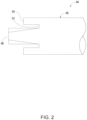
Fig. 2 is a schematic illustration representing example inserters of translators of end effectors according to the present disclosure. -
Fig. 3 illustrates an example fastener in the form of a collar nut. -
Fig. 4 is a flowchart schematically representing methods according to the present disclosure. -
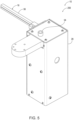
Fig. 5 is an isometric view of an example end effector according to the present disclosure. -
Fig. 6 is an isometric exploded view of the end effector ofFig. 5 . -
End effectors 10 for templating fasteners are disclosed herein. Generally, inFig. 1 , elements that are likely to be included in a given example are illustrated in solid lines, while elements that are optional to a given example or that correspond to a specific example are illustrated in broken lines. However, elements that are illustrated in solid lines are not essential to all examples of the present disclosure, and an element shown in solid lines may be omitted from a particular example without departing from the scope of the present disclosure. - As schematically represented in
Fig. 1 ,end effectors 10 generally comprise at least ahousing 28, apositioner 12, and atranslator 22. Thepositioner 12 is supported by thehousing 28 and is configured to sequentially receivefasteners 14 from asource 16 offasteners 14 into areceiving position 18 and sequentially movefasteners 14 from the receivingposition 18 to a deployingposition 20. Thetranslator 22 is supported by thehousing 28 relative to thepositioner 12 and is configured to sequentially translatefasteners 14 from the deployingposition 20 toports 24 of afastener holder 26, which also may be referred to as a fastener template. In some examples, thehousing 28 is configured to be operatively coupled to arobotic manipulator 30 for automation of the insertion offasteners 14 intofastener holders 26. Variousrobotic manipulators 30 may be used, including robotic arms, articulated robots, so-called cobots 60 (collaborative robots), delta robots, and other configurations of robots. - As schematically represented in
Fig. 1 , someend effectors 10 further comprise asensor 32 that is supported by thehousing 28 and that is configured to detect the presence of afastener 14 in thereceiving position 18. For example, thesensor 32 may be a distance sensor, a proximity sensor, or any other suitable sensor capable of detecting the presence of afastener 14 in thereceiving position 18. - Some
end effectors 10 further comprise or may be associated with acontroller 34 that is configured to operatively control thepositioner 12 and thetranslator 22. Thecontroller 34 may be any suitable device or devices that are configured to perform the functions of thecontroller 34 discussed herein. For example, thecontroller 34 may include one or more of an electronic controller, a dedicated controller, a special-purpose controller, a personal computer, a special-purpose computer, a display device, a logic device, a memory device, and/or a memory device having computer readable media suitable for storing computer-executable instructions for implementing aspects of systems and/or methods according to the present disclosure. InFig. 1 , lightning bolts associated with therobotic manipulator 30, thesensor 32, and thecontroller 34 schematically represent signals and/or other communication. Such communication may be wired or wireless. - In some examples, the
controller 34 is configured to receive a signal from thesensor 32 indicating the presence of afastener 14 in thereceiving position 18. In such examples, thecontroller 34 is configured to operate thepositioner 12 upon receipt of the signal from thesensor 32, and thecontroller 34 is configured to operate thetranslator 22 following operation of thepositioner 12. Accordingly, thepositioner 12 will only operate (i.e., attempt to move afastener 14 from the receivingposition 18 to the deploying position 20) when afastener 14 is detected as being present in thereceiving position 18. - In some examples and as schematically illustrated in
Fig. 1 , thepositioner 12 comprises arotatable structure 36 and a motor 40 (e.g., a stepper motor). Therotatable structure 36 defines a plurality ofchannels 38, with eachchannel 38 being configured to receive afastener 14 and sequentially define thereceiving position 18 and the deployingposition 20. Themotor 40 is operatively coupled to therotatable structure 36 and is configured to selectively rotate therotatable structure 36. Accordingly, therotatable structure 36 receives afastener 14 in achannel 38 defining thereceiving position 18 and then rotates to operatively position thefastener 14 in the deployingposition 20. Any number ofchannels 38 may be provided, including two, three, four, or more than fourchannels 38, which may be generally evenly spaced about therotatable structure 36. Themotor 40 therefore is configured to selectively rotate the rotatable structure 36 a corresponding angle (e.g., 180°, 120°, 90°, or so forth), such as responsive to a command from thecontroller 34 and responsive to receipt of a signal from thesensor 32. - As schematically illustrated in
Fig. 1 , in some examples ofend effectors 10, thetranslator 22 comprises alinear actuator 42 that is supported by thehousing 28, that is aligned with the deployingposition 20, and that is configured to sequentially and linearly translatefasteners 14 away from the deployingposition 20 and toward aport 24 of afastener holder 26. Examples oflinear actuators 42 include pneumatic actuators and hydraulic actuators, which sometimes are referred to as pneumatic cylinders and hydraulic cylinders. - In some examples, the
translator 22 comprises aninserter 44 that is configured to operatively engage and mate with afastener 14 in the deployingposition 20. Theinserter 44 may take various forms and structures such that it is configured to be operatively translated by thetranslator 22 to engage afastener 14 in the deploying position and insert thefastener 14 into aport 24 of afastener holder 26. In particular, theinserter 44 may be configured to engage and mate with a particular configuration offastener 14, such as a collar nut. With reference to the schematic illustration of a portion of aninserter 44 inFig. 2 , in some examples, theinserter 44 comprises anend region 46 that is configured to operatively engage and mate with afastener 14 in the deployingposition 20, and theend region 46 comprises anelongate tip 48 and arim 50 that extends circumferentially around theelongate tip 48. Theelongate tip 48 and therim 50 define acircumferential channel 52 between theelongate tip 48 and therim 50. In some examples, theelongate tip 48 is frustoconical, and in some examples, theelongate tip 48 extends beyond therim 50. Accordingly, such a configuredinserter 44 may configured for use withcollar nuts 62, an example of which is illustrated inFig. 3 . In particular, theelongate tip 48 of such aninserter 44 extends into theinternal passage 64 of thecollar nut 62 and with the collar nut'sgasket 66 being received within thecircumferential channel 52 of theinserter 44, such that thegasket 66 does not engage theinserter 44 at all. Accordingly, the integrity of thegasket 66 is not damaged or otherwise compromised in any way when thecollar nut 62 is engaged and translated by theinserter 44. - With continued reference to the schematic illustration of
Fig. 1 , someend effectors 10 further comprise aninsertion guide 54 that is supported by thehousing 28, that is aligned with the deployingposition 20, and that is configured to operatively guide afastener 14 into aport 24 of thefastener holder 26. As an example, theinsertion guide 54 may be a hollow cylinder or other tube that is appropriately shaped to permit operative translation of a fastener through theinsertion guide 54. Theinsertion guide 54 may extend from thehousing 28 to engage or otherwise be placed in close proximity to afastener holder 26 without thehousing 28 and the remainder of theend effector 10 coming into contact or otherwise interfering with thefastener holder 26. - In some examples of
end effectors 10, thesource 16 offasteners 14 comprises a gravity-fedcartridge 56 that is supported by thehousing 28, or that it configured to be selectively supported by thehousing 28, to deliverfasteners 14 to thereceiving position 18. In particular, the gravity-fed cartridge may have an internal cross-sectional shape that corresponds to a particular fastener configuration, such as a collar nut, so that thefasteners 14 can only be inserted into the gravity-fed cartridge in a desired orientation for delivery to thereceiving position 18. - In other examples, the
source 16 offasteners 14 comprises apneumatic feed system 58 that is coupled to thehousing 28, or that is configured to be selectively coupled to thehousing 28, and that is configured to pneumatically deliverfasteners 14 to thereceiving position 18. Other configurations ofsources 16 also are within the scope of the present disclosure. - Also within the scope of the present disclosure are systems 11 that comprise a plurality of the
end effectors 10, with eachend effector 10 of the plurality ofend effectors 10 being configured to work with a distinct size and/or configuration offastener 14. For example, a manufacturing facility may utilizedistinct end effectors 10 for templating distinct configurations offasteners 14 in multiple configurations offastener holders 26. -
Fig. 4 schematically provides a flowchart that represents illustrative, non-exclusive examples ofrobotic methods 100 according to the present disclosure. InFig. 4 , some steps are illustrated in dashed boxes indicating that such steps may be optional or may correspond to an optional version of arobotic method 100 according to the present disclosure. That said, not allrobotic methods 100 according to the present disclosure are required to include the steps illustrated in solid boxes. Therobotic methods 100 and steps illustrated inFig. 4 are not limiting and other methods and steps are within the scope of the present disclosure, including methods having greater than or fewer than the number of steps illustrated, as understood from the discussions herein. - With reference to
Fig. 4 and also toFig. 1 and theexample end effectors 10 represented therein,robotic methods 100 comprise at least sequentially receiving 102fasteners 14 from asource 16 offasteners 14 into a receivingposition 18, sequentially moving 104fasteners 14 from the receivingposition 18 to a deployingposition 20, and sequentially translating 106fasteners 14 from the deployingposition 20 toports 24 of afastener holder 26. - Some
robotic methods 100 further comprise sequentially sensing 108 the presence offasteners 14 in the receivingposition 18, such that the sequentially moving 104 is performed responsive to the sequentiallysensing 108. - In some examples of
robotic methods 100, the sequentially moving 104 comprises rotating 110. - In some examples of
robotic methods 100, the sequentially translating 106 comprises linearly translating 112. - In some examples of
robotic methods 100, the sequentially receiving 102 comprises receiving viagravity 114, such as via a gravity-fedcartridge 56. - In some examples of
robotic methods 100, the sequentially receiving 102 comprises pneumatically receiving 116, such as via apneumatic feed system 58. - Turning now to
Figs. 5 and6 , an illustrative non-exclusive example of anend effector 10 in the form of anend effector 200 is illustrated. Where appropriate, the reference numerals from the schematic illustration ofFig. 1 are used to designate corresponding parts of theend effector 200; however, the example ofFigs. 5 and6 is non-exclusive and does not limitend effectors 10 to the illustrated embodiment of theend effector 200. That is,end effectors 10 are not limited to the specific embodiment of theillustrated end effector 200, and endeffectors 10 may incorporate any number of the various aspects, configurations, characteristics, properties, etc. ofend effectors 10 that are illustrated in and discussed with reference to the schematic representations ofFigs. 1-3 and/or the embodiment ofFigs. 5 and6 , as well as variations thereof, without requiring the inclusion of all such aspects, configurations, characteristics, properties, etc. For the purpose of brevity, each previously discussed component, part, portion, aspect, region, etc. or variants thereof may not be discussed, illustrated, and/or labeled again with respect to theend effector 200; however, it is within the scope of the present disclosure that the previously discussed features, variants, etc. may be utilized with theend effector 200. - As seen in
Figs. 5 and6 , theend effector 200 is an example of anend effector 10 whosesource 16 offasteners 14 is a gravity-fedcartridge 56. Theend effector 200 comprises aninsertion guide 54 supported by thehousing 28. As seen inFig. 6 , thepositioner 12 of theend effector 200 comprises arotatable structure 36 coupled to amotor 40. Therotatable structure 36 defines fourchannels 38 spaced evenly about therotatable structure 36. Thetranslator 22 of theend effector 200 comprises alinear actuator 42 and aninserter 44. Theinserter 44 of theend effector 200 comprises anend region 46 that is configured to operatively engage with collar nuts 62. - Illustrative, non-exclusive examples of inventive subject matter according to the present disclosure are described in the following enumerated paragraphs:
- A. An end effector (10), comprising:
- a housing (28);
- a positioner (12) supported by the housing (28) and configured to sequentially receive fasteners (14) from a source (16) of the fasteners (14) into a receiving position (18) and sequentially move the fasteners (14) from the receiving position (18) to a deploying position (20); and
- a translator (22) supported by the housing (28) relative to the positioner (12) and configured to sequentially translate the fasteners (14) from the deploying position (20) to ports (24) of a fastener holder (26).
- A1. The end effector (10) of paragraph A1, wherein the housing (28) is configured to be operatively coupled to a robotic manipulator (30).
- A2. The end effector (10) of any of paragraphs A-A1, further comprising a sensor (32) supported by the housing (28) and configured to detect presence of a fastener (14) in the receiving position (18).
- A2.1. The end effector (10) of paragraph A2, wherein the sensor (32) is a distance sensor.
- A2.2. The end effector (10) of paragraph A2, wherein the sensor (32) is a proximity sensor.
- A3. The end effector (10) of any of paragraphs A-A2.2, further comprising a controller (34) configured to operatively control the positioner (12) and the translator (22).
- A3.1. The end effector (10) of paragraph A3 when depending from paragraph A2,
- wherein the controller (34) is configured to receive a signal from the sensor (32) indicating the presence of a fastener (14) in the receiving position (18);
- wherein the controller (34) is configured to operate the positioner (12) upon receipt of the signal from the sensor (32); and
- wherein the controller (34) is configured to operate the translator (22) following operation of the positioner (12).
- A4. The end effector (10) of any of paragraphs A-A3.1, wherein the positioner (12) comprises:
- a rotatable structure (36) defining a plurality of channels (38) each configured to receive a fastener (14) and sequentially define the receiving position (18) and the deploying position (20); and
- a motor (40) operatively coupled to the rotatable structure (36) and configured to selectively rotate the rotatable structure (36).
- A4.1. The end effector (10) of paragraph A4, wherein the motor (40) is a stepper motor.
- A5. The end effector (10) of any of paragraphs A-A4.1, wherein the translator (22) comprises a linear actuator (42) supported by the housing (28), aligned with the deploying position (20), and configured to sequentially and linearly translate the fasteners (14) away from the deploying position (20).
- A6. The end effector (10) of any of paragraphs A-A5, wherein the translator (22) comprises an inserter (44) configured to operatively engage and mate with a fastener (14) in the deploying position (20).
- A6.1. The end effector (10) of paragraph A6, wherein the inserter (44) comprises an end region (46) configured to operatively engage and mate with a fastener (14) in the deploying position (20), and wherein the end region (46) comprises:
- an elongate tip (48); and
- a rim (50) extending circumferentially around the elongate tip (48), wherein the elongate tip (48) and the rim (50) define a circumferential channel (52) between the elongate tip (48) and the rim (50).
- A6.1.1. The end effector (10) of paragraph A6.1, wherein the elongate tip (48) is frustoconical.
- A6.1.2. The end effector (10) of any of paragraphs A6.1-A6.1.1, wherein the elongate tip (48) extends beyond the rim (50).
- A7. The end effector (10) of any of paragraphs A-A6.1.2, further comprising an insertion guide (54) supported by the housing (28), aligned with the deploying position (20), and configured to operatively guide a fastener (14) into a port (24) of the fastener holder (26).
- A8. The end effector (10) of any of paragraphs A-A7, further comprising the fastener holder (26).
- A9. The end effector (10) of any of paragraphs A-A8, further comprising the source (16) of the fasteners (14).
- A9.1. The end effector (10) of paragraph A9, wherein the source (16) comprises a gravity-fed cartridge (56) supported by the housing (28) to deliver the fasteners (14) to the receiving position (18).
- A9.2. The end effector (10) of paragraph A9, wherein the source (16) comprises a pneumatic feed system (58) coupled to the housing (28) and configured to pneumatically deliver the fasteners (14) to the receiving position (18).
- A10. The end effector (10) of any of paragraphs A-A9.2, further comprising a/the robotic manipulator (30) operatively coupled to the housing (28).
- A10.1. The end effector (10) of paragraph A10, wherein the robotic manipulator (30) comprises a cobot (60).
- A11. The end effector (10) of any of paragraphs A-A10.1, wherein the fasteners (14) are collar nuts.
- B. A system (11), comprising a plurality of the end effectors (10) of any of paragraphs A-A11, wherein each end effector (10) of the plurality of end effectors (10) is configured to work with a distinct size and/or configuration of fastener (14).
- C. A robotic method (100), comprising:
- sequentially receiving (102) fasteners (14) from a source (16) of the fasteners (14) into a receiving position (18);
- sequentially moving (104) the fasteners (14) from the receiving position (18) to a deploying position (20); and
- sequentially translating (106) the fasteners (14) from the deploying position (20) to ports (24) of a fastener holder (26).
- C1. The robotic method (100) of paragraph C, further comprising:
- sequentially sensing (108) the presence of the fasteners (14) in the receiving position (18);
- wherein the sequentially moving (104) is performed responsive to the sequentially sensing (108).
- C2. The robotic method (100) of any of paragraphs C-C1, wherein the sequentially moving (104) comprises rotating (110).
- C3. The robotic method (100) of any of paragraphs C-C2, wherein the sequentially translating (106) comprises linearly translating (112).
- C4. The robotic method (100) of any of paragraphs C-C3, wherein the sequentially receiving (102) comprises receiving via gravity (114).
- C5. The robotic method (100) of any of paragraphs C-C4, wherein the sequentially receiving (102) comprises pneumatically receiving (116).
- C6. The robotic method (100) of any of paragraphs C-C5, wherein the fasteners (14) are collar nuts.
- C7. The robotic method (100) of any of paragraphs C-C6, wherein the method (100) is performed by the end effector (10) of any of paragraphs A-A11.
- D. Use of the end effector (10) of any of paragraphs A-A11 to fill the ports (24) of the fastener holder (26) with the fasteners (14).
- As used herein, the terms "adapted" and "configured" mean that the element, component, or other subject matter is designed and/or intended to perform a given function. Thus, the use of the terms "adapted" and "configured" should not be construed to mean that a given element, component, or other subject matter is simply "capable of" performing a given function but that the element, component, and/or other subject matter is specifically selected, created, implemented, utilized, programmed, and/or designed for the purpose of performing the function. It is also within the scope of the present disclosure that elements, components, and/or other recited subject matter that is recited as being adapted to perform a particular function may additionally or alternatively be described as being configured to perform that function, and vice versa. Similarly, subject matter that is recited as being configured to perform a particular function may additionally or alternatively be described as being operative to perform that function.
- As used herein, the term "and/or" placed between a first entity and a second entity means one of (1) the first entity, (2) the second entity, and (3) the first entity and the second entity. Multiple entries listed with "and/or" should be construed in the same manner, i.e., "one or more" of the entities so conjoined. Other entities optionally may be present other than the entities specifically identified by the "and/or" clause, whether related or unrelated to those entities specifically identified. Thus, as a nonlimiting example, a reference to "A and/or B," when used in conjunction with open-ended language such as "comprising," may refer, in one example, to A only (optionally including entities other than B); in another example, to B only (optionally including entities other than A); in yet another example, to both A and B (optionally including other entities). These entities may refer to elements, actions, structures, steps, operations, values, and the like.
- The various disclosed elements of apparatuses and steps of methods disclosed herein are not required to all apparatuses and methods according to the present disclosure, and the present disclosure includes all novel and non-obvious combinations and subcombinations of the various elements and steps disclosed herein. Moreover, one or more of the various elements and steps disclosed herein may define independent inventive subject matter that is separate and apart from the whole of a disclosed apparatus or method. Accordingly, such inventive subject matter is not required to be associated with the specific apparatuses and methods that are expressly disclosed herein, and such inventive subject matter may find utility in apparatuses and/or methods that are not expressly disclosed herein.
Claims (15)
- An end effector, comprising:a housing (28);a positioner (12) supported by the housing (28) and configured to sequentially receive fasteners (14) from a source (16) of the fasteners (14) into a receiving position (18) and sequentially move the fasteners (14) from the receiving position (18) to a deploying position (20); anda translator (22) supported by the housing (28) relative to the positioner (12) and configured to sequentially translate the fasteners (14) from the deploying position (20) to ports (24) of a fastener holder (26).
- The end effector (10) of claim 1, wherein the housing (28) is configured to be operatively coupled to a robotic manipulator (30).
- The end effector (10) of claim 1 or 2, further comprising a sensor (32) supported by the housing (28) and configured to detect the presence of a fastener (14) in the receiving position (18), in particular wherein the sensor (32) is a distance sensor.
- The end effector (10) of claim 3, further comprising a controller (34) configured to operatively control the positioner (12) and the translator (22), wherein the controller (34) is configured to receive a signal from the sensor (32) indicating the presence of a fastener (14) in the receiving position (18), wherein the controller (34) is configured to operate the positioner (12) upon receipt of the signal from the sensor (32), and wherein the controller (34) is configured to operate the translator (22) following operation of the positioner (12).
- The end effector (10) of any of claims 1 to 4, wherein the positioner (12) comprises:a rotatable structure (36) defining a plurality of channels (38) each configured to receive a fastener (14) and sequentially define the receiving position (18) and the deploying position (20); anda motor (40) operatively coupled to the rotatable structure (36) and configured to selectively rotate the rotatable structure (36).
- The end effector (10) of any of claims 1 to 5, wherein the translator (22) comprises a linear actuator (42) supported by the housing (28), aligned with the deploying position (20), and configured to sequentially and linearly translate the fasteners (14) away from the deploying position (20).
- The end effector (10) of any of claims 1 to 6, wherein the translator (22) comprises an inserter (44) configured to operatively engage and mate with a fastener (14) in the deploying position (20).
- The end effector (10) of claim 7, wherein the inserter (44) comprises an end region (46) configured to operatively engage and mate with a fastener (14) in the deploying position (20), and wherein the end region (46) comprises:an elongate tip (48), in particular wherein the elongate tip (48) is frustoconical; anda rim (50) extending circumferentially around the elongate tip (48), wherein the elongate tip (48) and the rim (50) define a circumferential channel (52) between the elongate tip (48) and the rim (50), in particular wherein the elongate tip (48) extends beyond the rim (50).
- The end effector (10) of any of claims 1 to 8, further comprising an insertion guide (54) supported by the housing (28), aligned with the deploying position (20), and configured to operatively guide a fastener (14) into a port (24) of the fastener holder (26).
- The end effector (10) of any of claims 1 to 9, further comprising the fastener holder (26).
- The end effector (10) of any of claims 1 to 10, further comprising the source (16) of the fasteners (14), in particular wherein either the source (16) comprises a gravity-fed cartridge (56) supported by the housing (28) to deliver the fasteners (14) to the receiving position (18) or the source (16) comprises a pneumatic feed system (58) coupled to the housing (28) and configured to pneumatically deliver the fasteners (14) to the receiving position (18).
- The end effector (10) of any of claims 1 to 11, further comprising a robotic manipulator (30) operatively coupled to the housing (28).
- The end effector (10) of any of claims 1 to 12, wherein the fasteners (14) are collar nuts.
- A system, comprising a plurality of the end effectors (10) of any of claims 1 to 13, wherein each end effector (10) of the plurality of end effectors (10) is configured to work with a distinct size and/or configuration of fastener (14).
- A robotic method (100), comprising:sequentially receiving (102) fasteners (14) from a source (16) of the fasteners (14) into a receiving position (18);sequentially moving (104) the fasteners (14) from the receiving position (18) to a deploying position (20); andsequentially translating (106) the fasteners (14) from the deploying position (20) to ports (24) of a fastener holder (26).
Applications Claiming Priority (1)
| Application Number | Priority Date | Filing Date | Title |
|---|---|---|---|
| US18/528,563 US12466086B2 (en) | 2023-12-04 | 2023-12-04 | Robotic end effectors for templating fasteners and related systems and methods |
Publications (2)
| Publication Number | Publication Date |
|---|---|
| EP4566749A2 true EP4566749A2 (en) | 2025-06-11 |
| EP4566749A3 EP4566749A3 (en) | 2025-12-17 |
Family
ID=92583392
Family Applications (1)
| Application Number | Title | Priority Date | Filing Date |
|---|---|---|---|
| EP24196624.1A Pending EP4566749A3 (en) | 2023-12-04 | 2024-08-27 | Robotic end effectors for templating fasteners and related systems and methods |
Country Status (2)
| Country | Link |
|---|---|
| US (1) | US12466086B2 (en) |
| EP (1) | EP4566749A3 (en) |
Family Cites Families (31)
| Publication number | Priority date | Publication date | Assignee | Title |
|---|---|---|---|---|
| GB191327049A (en) | 1912-11-23 | 1914-05-07 | Siemens Ag | Improvements in Rivetting Apparatus. |
| US1590578A (en) | 1922-07-17 | 1926-06-29 | Harris Columbus Whiteman | Oil dispenser |
| DE517372C (en) | 1929-01-28 | 1931-02-06 | Vormals Skodawerke Ag | Centering device for riveting machines |
| US3711006A (en) | 1971-08-23 | 1973-01-16 | Northrop Corp | Nutplate installation device |
| SE447708B (en) | 1983-10-21 | 1986-12-08 | Atlas Copco Ab | DEVICE FOR JOINING MEDIUM RIVING OF TWO OR MORE SECTIONS INCLUDED IN A CONSTRUCTION CONSISTING OF DISCOVERY ELEMENTS |
| DE3535761C1 (en) | 1985-10-07 | 1987-03-26 | Messerschmitt Boelkow Blohm | Riveting machine |
| US4736519A (en) | 1986-09-30 | 1988-04-12 | The Boeing Company | Nutplate installation tool |
| DE3715927A1 (en) | 1987-05-13 | 1988-12-01 | Messerschmitt Boelkow Blohm | DEVICE AND METHOD FOR AUTOMATICALLY CONTROLLED DRILL SUNNING AND RIVETING WITH THE AID OF AT LEAST TWO-PIECE CONNECTING ELEMENTS |
| US4885836A (en) | 1988-04-19 | 1989-12-12 | Imta | Riveting process and apparatus |
| DE3822435A1 (en) | 1988-07-02 | 1990-01-04 | Fraunhofer Ges Forschung | Assembly device for precise positioning and mounting of parts with vibration support |
| JPH0584685A (en) | 1991-09-26 | 1993-04-06 | Toshiba Corp | End effector for manipulator |
| US5214837A (en) | 1991-11-04 | 1993-06-01 | Teledyne Ryan Aeronautical, Division Of Teledyne Industries, Inc. | Automatic riveting nutplate installation device and method of riveting a nutplate to a workpiece |
| DE4320282A1 (en) | 1993-06-18 | 1994-12-22 | Dornier Luftfahrt | Apparatus for setting blind rivets |
| US5611130A (en) | 1993-06-28 | 1997-03-18 | Gemcor Engineering Corp. | Multi-position rotary head apparatus |
| FR2722437A1 (en) | 1994-07-12 | 1996-01-19 | Darsouze Patrick | Riveting tool for assembly of sheets for airframes of aeroplane |
| JPH09266613A (en) | 1996-03-27 | 1997-10-07 | Aichi Corp | Holding device |
| US6172374B1 (en) | 1997-11-26 | 2001-01-09 | The Boeing Company | Dual laser homing sensor |
| SE511704C2 (en) | 1998-03-19 | 1999-11-08 | Saab Ab | Method and apparatus for mounting the wing |
| EP1112131A4 (en) | 1998-09-11 | 2003-04-02 | Gen Electro Mech Corp | Rotary turret head apparatus |
| DE102004005859A1 (en) | 2004-02-05 | 2005-08-25 | Claas Fertigungstechnik Gmbh | Device for fixing rivet elements in components |
| DE102005028055A1 (en) * | 2005-06-16 | 2006-12-28 | Brötje-Automation GmbH | Rivet selection and fixing device |
| JP2008183637A (en) | 2007-01-26 | 2008-08-14 | Sharp Corp | HOLDING DEVICE AND CONVEYING DEVICE HAVING THE SAME |
| GB0818401D0 (en) * | 2008-10-08 | 2008-11-12 | Henrob Ltd | Fastener feed method and apparatus |
| US9802715B2 (en) * | 2012-03-29 | 2017-10-31 | The Boeing Company | Fastener systems that provide EME protection |
| US9937549B2 (en) | 2014-07-09 | 2018-04-10 | The Boeing Company | Two-stage riveting |
| DE102016108874A1 (en) * | 2016-05-13 | 2017-11-16 | Broetje-Automation Gmbh | Method for filling a rivet cassette with rivet elements |
| DE102017114972A1 (en) * | 2017-04-03 | 2018-10-04 | Broetje-Automation Gmbh | Method for supplying a riveting machine with rivet elements |
| US10792816B2 (en) | 2017-12-05 | 2020-10-06 | The Boeing Company | Portable programmable machines, robotic end effectors, and related methods |
| US10987767B2 (en) | 2018-12-17 | 2021-04-27 | The Boeing Company | Receiver-fastener apparatuses and systems for joining panels |
| US10981277B2 (en) | 2018-12-17 | 2021-04-20 | The Boeing Company | Shank-fastener apparatuses and methods for joining panels |
| GB201908900D0 (en) * | 2019-06-21 | 2019-08-07 | Atlas Copco Ias Uk Ltd | Fastener delivery apparatus |
-
2023
- 2023-12-04 US US18/528,563 patent/US12466086B2/en active Active
-
2024
- 2024-08-27 EP EP24196624.1A patent/EP4566749A3/en active Pending
Also Published As
| Publication number | Publication date |
|---|---|
| US12466086B2 (en) | 2025-11-11 |
| US20250178211A1 (en) | 2025-06-05 |
| EP4566749A3 (en) | 2025-12-17 |
Similar Documents
| Publication | Publication Date | Title |
|---|---|---|
| EP2350750B1 (en) | A method and an apparatus for calibration of an industrial robot system | |
| US20200180116A1 (en) | Gripping system with clamp device and method of using the same | |
| US5297238A (en) | Robot end-effector terminal control frame (TCF) calibration method and device | |
| EP4074444A1 (en) | Robotic drill system and method of drilling with a robotic drill system | |
| US10315311B2 (en) | Robots, robotic systems, and related methods | |
| US20010024044A1 (en) | Work chucking/inserting apparatus and assembling unit | |
| Liu et al. | Identification of position independent geometric errors of rotary axes for five-axis machine tools with structural restrictions | |
| CN104203504B (en) | Robot system | |
| US10022872B2 (en) | Self-contained modular manufacturing tool responsive to locally stored historical data | |
| US20140364986A1 (en) | Robot system | |
| CN113561217A (en) | Drive mechanism, robot apparatus measurement and control method, and part manufacturing method | |
| CN105945940B (en) | A cargo handling robot for warehouse | |
| US10025299B2 (en) | System and method for self-contained modular manufacturing device having nested controllers | |
| CN113021017A (en) | Shape-following self-adaptive intelligent 3D detection and processing system | |
| US12466086B2 (en) | Robotic end effectors for templating fasteners and related systems and methods | |
| Matthaiakis et al. | Flexible programming tool enabling synergy between human and robot | |
| BR112017013244B1 (en) | ROBOT EFFECTER FOR INSTALLATION OF MECHANICAL FASTENERS AND ROBOT | |
| US20220332519A1 (en) | Automated workpiece inversion systems and related methods | |
| US20230045651A1 (en) | Method and electronic device, system and computer readable medium for calibration | |
| US20250033152A1 (en) | End effector and methods of use | |
| Yao | Design and experiment of a robot automatic drilling system | |
| Drouot et al. | Towards industry 4.0: the future automated aircraft assembly demonstrator | |
| Mehlenhoff et al. | Solution for automated drilling in composite structures with a standard articulating robot system | |
| Schneider et al. | Combining holistic programming with kinematic parameter optimisation for robot machining | |
| Cho et al. | Robotic drilling: A review of present challenges |
Legal Events
| Date | Code | Title | Description |
|---|---|---|---|
| PUAI | Public reference made under article 153(3) epc to a published international application that has entered the european phase |
Free format text: ORIGINAL CODE: 0009012 |
|
| STAA | Information on the status of an ep patent application or granted ep patent |
Free format text: STATUS: THE APPLICATION HAS BEEN PUBLISHED |
|
| AK | Designated contracting states |
Kind code of ref document: A2 Designated state(s): AL AT BE BG CH CY CZ DE DK EE ES FI FR GB GR HR HU IE IS IT LI LT LU LV MC ME MK MT NL NO PL PT RO RS SE SI SK SM TR |
|
| PUAL | Search report despatched |
Free format text: ORIGINAL CODE: 0009013 |
|
| AK | Designated contracting states |
Kind code of ref document: A3 Designated state(s): AL AT BE BG CH CY CZ DE DK EE ES FI FR GB GR HR HU IE IS IT LI LT LU LV MC ME MK MT NL NO PL PT RO RS SE SI SK SM TR |
|
| RIC1 | Information provided on ipc code assigned before grant |
Ipc: B23P 19/00 20060101AFI20251110BHEP Ipc: B21J 15/32 20060101ALI20251110BHEP Ipc: B25J 15/00 20060101ALI20251110BHEP Ipc: B23K 9/20 20060101ALI20251110BHEP Ipc: B23P 19/06 20060101ALN20251110BHEP |
|
| STAA | Information on the status of an ep patent application or granted ep patent |
Free format text: STATUS: REQUEST FOR EXAMINATION WAS MADE |
|
| 17P | Request for examination filed |
Effective date: 20260504 |