TECHNICAL FIELD
-
The present disclosure relates to an assembly of a main shaft of a crusher, and more particularly, to a guiding tool and a method of installing a head nut of the crusher using the guiding tool.
BACKGROUND
-
Crushers, such as cone crushers and gyratory crushers, are used in various industries such as mining, and quarry for crushing bigger size materials such as rock into smaller particles to form sand and gravels for various applications. Due to the nature of application, the crusher is surrounded by huge amount of dust particles, which lead to regular maintenance and service of the crusher as the parts such as mantle and concaves wear faster than expected service life. High dead weight and complexity of the parts of the crusher further lead to high maintenance cost and operating cost. Further, due to the high dead weight of the parts, the assembly of the crusher, especially, main shaft and the associated parts such as the head nut are assembled within the crusher housing using lifting equipment. Precisely maneuvering the lifting equipment to control movement of the parts and aligning the parts each other without any damage therein is tedious and time consuming tasks. Huge lead time and damage to the part may further increase the operating cost.
-
The head nut is, generally, inserted over the main shaft for securing the mantle upon replacement thereof on the main shaft. The head is inserted over the main shaft using the lifting equipment and tightened over the thread portion of the main shaft. The existing method of inserting the head nut over the main shaft and tightening the head nut with the main shaft to engage the mantle is a tedious and a laborious process. Due to the high dead weight, the assembly process becomes difficult, and problems arises in handling the head nut. Installing and guiding the head nut are often associated with damage to the thread of the main shaft or a supporting part attached to the main shaft, which further lead to down time or longer installation time. Hence, there is a need remains to develop a tool that can easily and conveniently install the head nut on to the main shaft without damaging the threads of the main shaft.
SUMMARY
-
In one aspect of the present disclosure, a guiding tool for installing a head nut of a crusher is provided. The guiding tool includes a substantial cylindrical body having a center hole configured to be inserted over a main shaft of the crusher, and a first thread portion defined at an outer circumference of the cylindrical body in conformance with a thread portion of the head nut. The guiding tool further includes an attachment disposed at a top end of the guiding tool to attach with a lifting equipment such that the guiding tool may be conveniently inserted over the main shaft due to high dead weight of the guiding tool. In an embodiment, a ring body is located above a mantle and attached to the main shaft and a second thread portion is defined on an outer circumference of the ring body. In some embodiments, the second thread portion may be defined on the main shaft to engage with the head nut.
-
The cylindrical body further includes a first mating surface configured to support with a second mating surface of the ring body. As such, the guiding tool inserted over the main shaft is supported on the ring body to align the first thread portion with the second thread portion. Particularly, an alignment mechanism is configured to align a thread output of the first thread portion of the cylindrical body with a thread input of the second thread portion of the ring body such that the first thread portion and the second thread portion together define a single thread portion to engage with the head nut. During an assembly of the head nut, the first thread portion of the cylindrical body aligns with the second thread portion associated with the main shaft. Upon alignment of the first thread portion and the second thread portion, the head nut is inserted over the main shaft and the first thread portion of the cylindrical body engages with the head nut. Further, the head nut is allowed to threadably move and engage with the second thread portion associated with the main shaft to secure the mantle disposed on the main shaft.
-
In some embodiments, the alignment mechanism includes a first alignment member defined in the cylindrical body, and a second alignment member defined in the ring body. The first alignment member is configured to engage with the second alignment member to align the first thread portion and the second thread portion. In certain embodiments, mutually engaging features may be provided in the guiding tool and the ring body such that the first thread portion and the second thread portion may be aligned easily within a short period time. In some embodiments, the alignment mechanism includes visual indicators to align the first thread portion with the second thread portion. The visual indicators may provide a low cost option to align the first thread portion and the second thread portion easily. Some examples of alignment members may be corresponding protrusions/indentations, interlocking joints, and male/female connectors. In some embodiments, a locking mechanism may be provided to lock the cylindrical body with the main shaft upon aligning the first thread portion with the second thread portion such that the misplacement of the first thread portion and the second thread portion may be avoided while engaging the head nut with the guiding tool. One or more fastening members may be used to lock the first thread portion with the second thread portion.
-
In another aspect of the present disclosure, a method of installing a head nut of a crusher is described. The method includes inserting a guiding tool over a main shaft of the crusher. The guiding tool includes a cylindrical body and a first thread portion defined at an outer circumference of the cylindrical body. The cylindrical body has a center hole having a diameter greater than a diameter of the main shaft. Upon insertion of the guiding tool, a first mating surface of the cylindrical body is supported on a second mating surface of the ring body. The method also includes aligning the first thread portion of the cylindrical body with a second thread portion associated with the main shaft using alignment mechanisms. In particular, a thread output of the first thread portion of the guiding tool is aligned with a thread input of the second thread portion of the ring body via the alignment mechanism.
-
In one embodiment, a first alignment member defined in the cylindrical body is engaged with a second alignment member defined in the ring body. In another embodiment, the first thread portion of the guiding tool may be aligned with the second thread portion of the ring body using visual indicators. In some embodiments, the guiding tool may be locked with the main shaft using a locking mechanism upon aligning the first thread portion with the second thread portion. One or more fastening members may be used to lock or align the first thread portion of the guiding tool with the second thread portion of the ring body. The head nut is further inserted over the cylindrical body, and engages the first thread portion of the cylindrical body with the head nut. The head nut is further engaged with the second thread portion of a ring body, which in turn engaged with the main shaft. In particular, the head nut is threadably moved from the first thread portion to the second thread portion to secure a mantle disposed on the main shaft.
-
In another aspect of the present disclosure, a method of removing a head nut of a crusher is described. The method includes inserting a guiding tool over a main shaft of the crusher. The guiding tool includes a cylindrical body and a first thread portion defined at an outer circumference of the cylindrical body. The cylindrical body has a center hole having a diameter greater than a diameter of the main shaft. Upon insertion of the guiding tool, a first mating surface of the cylindrical body is supported on a second mating surface of the ring body. The method also includes aligning the first thread portion of the cylindrical body with a second thread portion associated with the main shaft using alignment mechanisms. In particular, a thread output of the first thread portion of the guiding tool is aligned with a thread input of the second thread portion of the ring body via the alignment mechanism.
-
In some embodiments the head nut is threadably moved from the second thread portion to the first thread portion to loosen a mantle disposed on the main shaft. When the head nut is fully engaged with the first thread portion the head nut can be lifted off the crusher by means of the guiding tool.
-
In yet another aspect of the present disclosure sure, a tool kit for installing a head nut of a crusher is described. The tool kit includes a guiding tool for inserting over a main shaft of the crusher. The guiding tool includes a cylindrical body having a center hole configured to be inserted over the main shaft, and a first thread portion defined at an outer circumference of the cylindrical body, and configured to align with a second thread portion associated with the main shaft. The first thread portion of the cylindrical body is configured to engage with the head nut, and allow the head nut to threadably move and engage with the second thread portion associated with the main shaft to secure a mantle disposed on the main shaft. The tool kit also includes an alignment mechanism configured to align a thread output of the first thread portion of the cylindrical body with a thread input of a second thread portion associated with the main shaft. The guiding tool and the alignment mechanism may be packaged as a single unit, such as the tool kit, and used in the aftermarket for making the head nut assembly during the maintenance and service more efficient and less time consuming.
-
Other features and aspects of this disclosure will be apparent from the following description and the accompanying drawings.
BRIEF DESCRIPTION OF DRAWINGS
-
A better understanding of embodiments of the present disclosure (including alternatives and/or variations thereof) may be obtained with reference to the detailed description of the embodiments along with the following drawings, in which:
- FIG. 1 is a partial cross-sectional view of an exemplary crusher;
- FIG. 2 is an enlarged cross-sectional view of a portion of the crusher of FIG. 1 showing a head nut assembled with a main shaft;
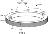
- FIG. 3 is a perspective view of a guiding tool used for installing the head nut on the main shaft, according to an embodiment of the present disclosure;
- FIG. 4A is a cross-sectional view of a ring body and the guiding tool showing an aligned position thereof during installation of the head nut, according to an embodiment of the present disclosure;
- FIG. 4B is a schematic cross-sectional view of the guiding tool and the ring body showing an alignment mechanism having alignment members, according to an embodiment of the present disclosure;
- FIG. 4C is a side view of the guiding tool and the ring body showing an alignment mechanism having visual indicators, according to an embodiment of the present disclosure;
- FIG. 4D is a schematic cross-sectional view of a locking mechanism, according to an embodiment of the present disclosure; and
- FIG. 5 is a schematic flow diagram of a method of installing the head nut in the crusher, according to an embodiment of the present disclosure.
DETAILED DESCRIPTION
-
Reference will now be made in detail to specific embodiments or features, examples of which are illustrated in the accompanying drawings. Wherever possible, corresponding or similar reference numbers will be used throughout the drawings to refer to the same or corresponding parts. Moreover, references to various elements described herein, are made collectively or individually when there may be more than one element of the same type. However, such references are merely exemplary in nature. It may be noted that any reference to elements in the singular may also be construed to relate to the plural and vice-versa without limiting the scope of the disclosure to the exact number or type of such elements unless set forth explicitly in the appended claim.
-
Referring to FIG. 1, a partial cross-sectional view of a crusher 100 is illustrated, according to an embodiment of the present disclosure. The crusher 100 is used for reducing bigger size materials such as, but not limited to, rocks into smaller size materials such as, but not limited to, sand, and gravel for various industrial and commercial applications. Various types of crusher include, but are not limited to, a gyratory crusher, a jaw crusher, and a cone crusher. For illustration purpose, a gyratory crusher is shown in FIG. 1 and explained various aspects of the present disclosure. However, the present disclosure may also be implemented in other types of crushers, such as the cone crusher, without limiting the scope of the present disclosure set by the claimed elements.
-
The crusher 100 includes a housing 102 to accommodate various operating elements thereof. The housing 102 includes a bottom shell 104 and a top shell 106 coupled each other via fastening members 108. In some embodiments, the housing 102 may include a bottom shell, a middle shell, and a top shell coupled each other via fastening members. The crusher 100 further includes a spider 110 coupled to the top shell 106. The spider 110 includes a pair of arms 112 having outer ends coupled to the top shell 106 and inner ends defining a cavity along a central axis 'CA' of the crusher 100 for receiving a top cylindrical portion 116 of a main shaft 120 of the crusher 100. A spider cap 122 is disposed on top of the spider 110 to enclose the cavity and an arm guard 124 is disposed around the pair of arms 112 of the spider 110. The spider 110 and the top shell 106 together configured to define an access opening for receiving the bigger size materials therethrough for crushing.
-
The bottom shell 104 includes a drive housing 130 for rotatably supporting a pinion shaft 132 disposed along a transverse axis `TA' defined perpendicular to the central axis 'CA' of the crusher 100. One end of the pinion shaft 132 is coupled to a pinion gear 134 and another end is connected to a drive system (not shown) for receiving a rotary power therefrom. The crusher 100 further includes an eccentric 140 rotatably supported in the drive housing 130. The eccentric 140 is a hollow cylindrical body having a bottom end engaged with a bevel gear 142, which in turn engaged with the pinion gear 134. As such, the rotary power from the drive system is transferred to the eccentric 140 via the pinion gear 134 and the bevel gear 142 to rotate the eccentric 140 about the central axis 'CA' of the crusher 100. The eccentric 140 defines a cavity along a longitudinal axis `LA' thereof to receive a bottom cylindrical portion 144 of the main shaft 120. The longitudinal axis `LA' of the cavity of the eccentric 140 is defined at an offset distance 'OD' from the central axis 'CA' of the crusher 100 such that the eccentric 140 is configured to cause oscillatory movement of the main shaft 120 about the central axis 'CA' of the crusher 100.
-
The crusher 100 further includes at least a part of a hydraulic system (not shown) for moving the main shaft 120 up or down. The hydraulic system includes a hydraulic cylinder and a piston slidably disposed within the hydraulic cylinder. The hydraulic cylinder is fluid tightly attached to the drive housing 130 below the eccentric 140 along the central axis 'CA' of the crusher 100. The piston is slidably disposed within the hydraulic cylinder in such a way to move the eccentric 140 up or down based on an actuation of the hydraulic system. The movement of the eccentric 140 causes movement of the main shaft 120 along the central axis 'CA' of the crusher 100.
-
The main shaft 120 is rotatably disposed within the housing 102 of the crusher 100. Particularly, the top cylindrical portion 116 is rotatably received within the cavity defined by the spider 110 and the bottom cylindrical portion 144 is received within the cavity defined by the eccentric 140. The main shaft 120 further includes a head center 150 defining a conical outer circumference 152 between the top cylindrical portion 116 and the bottom cylindrical portion 144. The conical outer circumference 152 of the main shaft 120 is further surrounded by a mantle 154, which is otherwise referred to as the main shaft liner. The conical outer circumference 152 of the main shaft 120 and the top shell 106 of the housing 102 together define a crushing chamber 156. An inner surface of the top shell 106 of the housing 102 is surrounded by concaves 158, which is otherwise referred to as the crushing chamber liner. The crusher 100 further includes a head nut 160 configured to secure the mantle 154 disposed on the conical outer circumference 152 of the main shaft 120. Particularly, the head nut 160 is configured to secure a position of the mantle 154 intact with respect to the main shaft 120.
-
During an operation of the crusher 100, the material is fed into the crushing chamber 156 of the housing 102 via the access opening defined between the top shell 106 and the spider 110. The pinion shaft 132 is coupled to the drive system such that the rotary power from the drive system is transferred to the eccentric 140 via the pinion gear 134 and the bevel gear 142. The eccentric 140 is engaged with the bottom cylindrical portion 144 of the main shaft 120 such that a rotational movement of the eccentric 140 causes a rotational movement of the main shaft 120 along the longitudinal axis 'LA'. Further, the offset distance `OD' between the longitudinal axis `LA' defined by the cavity of the eccentric 140 and the central axis 'CA' of the crusher 100 causes the oscillatory movement of the main shaft 120 about the central axis 'CA' of the crusher 100. A size at which the material to be crushed may be defined based on a gap `G1' defined between the mantle 154 and the concaves 158 at a lower portion thereof. The gap `G1' is varied by moving the main shaft 120 up or down with the help of the hydraulic system.
-
Referring to FIG. 2, an enlarged cross-sectional view of a portion `E' of FIG. 1 showing the head nut 160 installed with the main shaft 120 is illustrated, according to an embodiment of the present disclosure. The top cylindrical portion 116 of the main shaft 120 is configured to be rotatably received within the cavity defined by the spider 110. The head nut 160 includes a thread portion 202 configured to threadably engage with the main shaft 120. In an embodiment of the present disclosure, the thread portion 202 of the head nut 160 is configured to threadably engage with a ring body 204. The ring body 204 includes an outer circumference defining a thread portion in conformance with the thread portion 202 of the head nut 160. The thread portion defined on the outer circumference of the ring body 204 is hereinafter referred to as 'the second thread portion 206'. The ring body 204 further includes an inner circumference 208 configured to engage with a step portion 210 of the main shaft 120. In an example, the ring body 204 may be engaged with the step portion 210 of the main shaft 120 using a press fit, an interference fit, or any other coupling mechanisms known in the art. The ring body 204 further includes a top surface 212 and a bottom surface 214. The bottom surface 214 is configured to engage with a top end of the head center 150. In some embodiments, the main shaft 120 may include a thread portion, otherwise referred as the second thread portion 206, defined at the step portion 210 of the main shaft 120 configured to engage with the head nut 160. In such a case, the thread portion 202 of the head nut 160 is configured to engage with the thread portion of the main shaft 120. In some embodiments, a sleeve 216 may be disposed around the top cylindrical portion 116 of the main shaft 120. A bottom end of the sleeve 216 may include a thread portion configured to engage with the thread portion 202 of the head nut 160.
-
Referring to FIG. 3, a perspective view of a guiding tool 300 used for installing the head nut 160 with the main shaft 120 is illustrated, according to an embodiment of the present disclosure. The guiding tool 300 includes a substantial cylindrical body 302 having a top end 304 and a bottom end 306 defining a height. The height of the cylindrical body 302 may be substantially equal to a thickness of the head nut 160. The height of the cylindrical body 302 may also be greater than the thickness of the heat nut 160. The cylindrical body 302 has a center hole 308 configured to be inserted over the top cylindrical portion 116 of the main shaft 120. Particularly, the cylindrical body 302 includes the center hole 308 having a diameter greater than a diameter of the top cylindrical portion 116 of the main shaft 120 such that the cylindrical body 302 may be freely and easily inserted over the top cylindrical portion 116 of the main shaft 120.
-
The guiding tool 300 further includes a thread portion, which is alternatively referred to as 'the first thread portion 310', defined at an outer circumference 312 of the cylindrical body 302. The first thread portion 310 of the guiding tool 300 is defined in conformance with the thread portion 202 of the head nut 160. Particularly, dimensional specification of the first thread portion 310 of the guiding tool 300 is defined corresponding to the dimensional specification of the thread portion 202 of the head nut 160 such that the head nut 160 may be firmly engaged with the guiding tool 300. Referring to FIG. 2 and FIG. 3, the first thread portion 310 of the cylindrical body 302 is configured to align with the second thread portion 206 associated with the main shaft 120. In particular, the first thread portion 310 is configured to align with the second thread portion 206 of the ring body 204. The first thread portion 310 of the cylindrical body 302 is further configured to engage with the head nut 160, and allow the head nut 160 to threadably move and engage with the second thread portion 206 of the ring body 204 to secure the mantle 154 disposed on the main shaft 120.
-
In some embodiments, the guiding tool 300 further includes an attachment 314 disposed on the top end 304 of the cylindrical body 302. The attachment 314 is configured to attach with a coupling member of a lifting equipment. In the present disclosure, the guiding tool 300 includes a first attachment 314A and a second attachment 314B coupled to the top end 304 of the cylindrical body 302. Particularly, the first attachment 314A and the second attachment 314B are located on the top end 304 diametrically opposite to each other such that the guiding tool 300 may be horizontally balanced while inserting over the main shaft 120. In an alternative embodiment the guiding tool 300 may comprise at least two attachment points, such as 3 or 4 attachments points. If the guiding tool 300 comprises more than two attachment points, they are preferably located on the top end 304 of the cylindrical body 302 to form the edges of a regular polygon, e.g., an equilateral triangle or a quadrant. In an example, the attachment 314 may include, but are not limited to, a ring, a clamp, or any other device which is configured to couple with the coupling member of the lifting equipment. Particularly, the coupling member such as a hook may be configured to couple with the attachment 314 of the guiding tool 300. In one embodiment, the attachment 314 may be fixedly attached to the top end 304 of the cylindrical body 302 using a welding method. In another embodiment, the attachment 314 may be detachably attached to the top end 304 of the cylindrical body 302 using a threaded coupling method.
-
Referring to FIG. 4A, a cross-sectional view of the ring body 204 and the guiding tool 300 showing an aligned position thereof during an installation of the head nut 160 is illustrated, according to an embodiment of the present disclosure. As shown in FIG. 4A, the first thread portion 310 of the guiding tool 300 is configured to align with the second thread portion 206 of the ring body 204 when the guiding tool 300 is inserted over the top cylindrical portion 116 of the main shaft 120. In some embodiments, the guiding tool 300 includes an alignment mechanism 402 (shown in FIG. 4B) configured to align the first thread portion 310 of the guiding tool 300 with the second thread portion 206 of the ring body 204. Particularly, the alignment mechanism 402 is configured to align a thread output 404 of the first thread portion 310 of the cylindrical body 302 of the guiding tool 300 with a thread input 406 of the second thread portion 206 of the ring body 204. The thread output 404 of the first thread portion 310 may be otherwise referred to as 'the bottom edge' of the first thread portion 310 and the thread input 406 of the second thread portion 206 may be otherwise referred to as 'the top edge' of the second thread portion 206. In the aligned position of the first thread portion 310 and the second thread portion 206, the thread output 404 of the first thread portion 310 and the thread input 406 of the second thread portion 206 are merged each other to define a continuous thread pattern. In other words, the first thread portion 310 and the second thread portion 206 together form a single thread portion.
-
Referring to FIG. 4B, a schematic cross-sectional view of the alignment mechanism 402 is illustrated, according to an embodiment of the present disclosure. Referring to FIG. 3 and FIG. 4B, the cylindrical body 302 of the guiding tool 300 includes a first mating surface 408 defined at the bottom end 306 thereof. The first mating surface 408 of the cylindrical body 302 is configured to engage with the ring body 204 upon insertion of the guiding tool 300 over the top cylindrical portion 116 of the main shaft 120. In an embodiment, the first mating surface 408 of the cylindrical body 302 may be defined as a planar surface at the bottom end 306 thereof. The first mating surface 408 of the bottom end 306 of the cylindrical body 302 is configured to support with the top surface 212, which is otherwise referred to as 'the second mating surface 212' of the ring body 204. As such, the first mating surface 408 of the guiding tool 300 is configured to abut the second mating surface 212 of the ring body 204, and thereby to help align the first thread portion 310 of the guiding tool 300 with the second thread portion 206 of the ring body 204.
-
In some embodiments, the alignment mechanism 402 includes a first alignment member 410 defined in the cylindrical body 302 of the guiding tool 300 and a second alignment member 412 defined in the ring body 204. In one example, the first alignment member 410 may be a protrusion vertically extending from a planar surface at the bottom end 306 of the cylindrical body 302 and the second alignment member 412 may be a hole defined at the top surface 212 of the ring body 204 corresponding to a shape and a size of the first alignment member 410. As such, the second alignment member 412 defined in the ring body 204 is configured to engage with the first alignment member 410 of the guiding tool 300 to align the first thread portion 310 of the guiding tool 300 and the second thread portion 206 of ring body 204. In another example, the first alignment member 410 may be a hole defined at the bottom end 306 of the cylindrical body 302 and the second alignment member 412 may be a protrusion defined at the top surface 212 of the ring body 204.
-
Referring to FIG. 4C, a side view of the guiding tool 300 and the ring body 204 showing an alignment mechanism 414 is illustrated, according to another embodiment of the present disclosure. The alignment mechanism 414 includes visual indicators 416 to align the first thread portion 310 of the guiding tool 300 with the second thread portion 206 of the ring body 204. In an example, the visual indicators 416 may include an engraved marking at the bottom end 306 of the cylindrical body 302 of the guiding tool 300 and a corresponding engraved marking may be provided at the ring body 204. During, the installation of the head nut 160, the corresponding engraved markings may be aligned to align the first thread portion 310 of the guiding tool 300 with the second thread portion 206 of the ring body 204. In another example, the visual indicators 416 may include a color mark at the bottom end 306 of the cylindrical body 302 of the guiding tool 300 and a corresponding color mark may be provided at the ring body 204. During the installation of the head nut 160, the corresponding color marks may be aligned to align the first thread portion 310 of the guiding tool 300 with the second thread portion 206 of the ring body 204. Further, the visual indicators 416 may be used to align the first thread portion 310 of the guiding tool 300 with the second thread portion 206 of the ring body 204 after the first mating surface 408 of the cylindrical body 302 is rested on the second mating surface 212 of the ring body 204.
-
Referring to FIG. 4D, a schematic cross-sectional view of a locking mechanism 418 is illustrated, according to an embodiment of the present disclosure. The locking mechanism 418 is configured to lock the cylindrical body 302 of the guiding tool 300 with the ring body 204 upon aligning the first thread portion 310 with the second thread portion 206. In an embodiment, the guiding tool 300 includes one or more fastening members 420 to lock the first thread portion 310 with the second thread portion 206. A first receiving portion 422 may be defined in the cylindrical body 302 and a second receiving portion 424 may be defined in the ring body 204. The first receiving portion 422 and the second receiving portion 424 are configured to receive the fastening member 420 therein. In an example, the fastening member 420 may be a cylindrical bar configured to engage with the first receiving portion 422 and the second receiving portion 424. As such, the first thread portion 310 of the guiding tool 300 is locked with the second thread portion 206 of the ring body 204 during the installation of the head nut 160. In some embodiments, a through hole may be defined in the cylindrical body 302 and a threaded hole may be defined in the ring body 204, such that a bolt may be used to insert through the through hole of the cylindrical body 302 to engage with the threaded hole of the ring body 204 to firmly lock the cylindrical body 302 with the ring body 204.
-
Referring to FIG. 5, a schematic flow diagram of a method 500 of installing the head nut 160 of the crusher 100 is illustrated, according to an embodiment of the present disclosure. The order in which the method 500 described is not intended to be construed as a limitation, and any number of the described method steps can be combined in any order to implement the method 500. Additionally, individual steps may be removed or skipped from the method 500 without departing from the spirit and scope of the present disclosure. The method 500 of the present disclosure is illustrated with reference to the crusher 100 and the guiding tool 300 described in FIG. 1 through FIG. 4D.
-
At step 502, the method 500 includes inserting the guiding tool 300 over the main shaft 120. The guiding tool 300 includes the cylindrical body 302 having the top end 304 and the bottom end 306. The cylindrical body 302 has the center hole 308 having the diameter greater than the diameter of the main shaft 120. In particular, the diameter of the center hole 308 of the cylindrical body 302 is greater than the diameter of the top cylindrical portion 116 of the main shaft 120 such that the guiding tool 300 is freely inserted over the top cylindrical portion 116 of the main shaft 120. The guiding tool 300 further includes the first thread portion 310 defined at the outer circumference 312 of the cylindrical body 302. During an assembly of the crusher 100, the main shaft 120 is inserted within the housing 102 of the crusher 100 using the lifting equipment. Further, the mantle 154 is inserted over the main shaft 120 with the help of the lifting equipment, subsequently, the ring body 204 may be inserted over the top cylindrical portion 116 of the main shaft 120. The ring body 204 may be engaged with the main shaft 120 with the help of press fit or the interference fit. To position the mantle 154 over the conical outer circumference 152 of the main shaft 120, the head nut 160 is implemented. Further, to make the assembly of the head nut 160 with the main shaft 120 easier and less time consuming, the guiding tool 300 of the present disclosure is used. The guiding tool 300 may be inserted with the help of the lifting equipment. In particular, the coupling members of the lifting equipment may be used to couple with the attachments 314 provided at the top end 304 of the cylindrical body 302. As such, the guiding tool 300 may be freely and easily inserted over the main shaft 120.
-
At step 504, the method 500 includes aligning the first thread portion 310 of the cylindrical body 302 with the second thread portion 206 of the ring body 204. Upon inserting the guiding tool 300 over the top cylindrical portion 116, the method 500 includes engaging the first mating surface 408 of the cylindrical body 302 with the second mating surface 212 of the ring body 204. Particularly, the guiding tool 300 is supported over the ring body 204 to align the first thread portion 310 of the cylindrical body 302 with the second thread portion 206 of the ring body 204. The method 500 further includes aligning the thread output 404 of the first thread portion 310 of the guiding tool 300 with the thread input 406 of the second thread portion 206 of the ring body 204 via the alignment mechanism 402. Such that the first thread portion 310 and the second thread portion 206 together define the single thread portion for engaging with the head nut 160.
-
In some embodiments, the method 500 includes engaging the first alignment member 410 defined in the cylindrical body 302 with the second alignment member 412 defined in the ring body 204. The lifting equipment may be controlled to align the first alignment member 410 of the guiding tool 300 with the second alignment member 412 of the ring body 204 while moving the guiding tool 300 down over the main shaft 120. In some embodiments, the method 500 includes aligning the first thread portion 310 of the guiding tool 300 with the second thread portion 206 of the ring body 204 using the visual indicators 416. The method 500 further includes locking the guiding tool 300 with the main shaft 120 using the locking mechanism 418 upon aligning the first thread portion 310 with the second thread portion 206. In particular, the locking mechanism 418 locks the cylindrical body 302 of the guiding tool 300 with the ring body 204. The method 500 further includes aligning or locking the first thread portion 310 of the guiding tool 300 with the second thread portion 206 of the ring body 204 using the fastening members 420. Specifically, the fastening member 420 may be received within the second receiving portion 424 of the ring body 204, and the first receiving portion 422 of the guiding tool 300 may be aligned with the second receiving portion 424 to engage with the fastening member 420 while the guiding tool 300 is inserted over the main shaft 120.
-
At step 506, the method 500 includes threadably moving the head nut 160 from the first thread portion 310 to the second thread portion 206 to secure the mantle 154 disposed on the main shaft 120. In particular, the method 500 includes inserting the head nut 160 over the cylindrical body 302 and engaging the first thread portion 310 of the cylindrical body 302 with the head nut 160. In one embodiment of the present disclosure, the head nut 160 may be inserted over the main shaft 120 using the lifting equipment to engage with the first thread portion 310 of the guiding tool 300, which is already placed over the main shaft 120. In another embodiment, the head nut 160 may be engaged with the first thread portion 310 of the guiding tool outside the crusher 100 and the guiding tool 300 along with the head nut 160 may be inserted over the main shaft 120 with the help of lifting equipment. The method 500 further includes engaging the head nut 160 with the second thread portion 206 of the ring body 204.
-
The guiding tool 300 may also be utilized in a method for removing the head nut 160 from a crusher. The method comprising similar steps as already described but in a reversed order.
-
In some embodiments of the present disclosure, a tool kit for installing the head nut 160 on the main shaft 120 of the crusher 100 is illustrated with reference to FIG. 1 through FIG. 3, and various embodiments of alignment mechanisms are illustrated with reference to FIG. 4A through FIG. 4D. The tool kit includes the guiding tool 300, as described in FIG. 3, for inserting over the main shaft 120. The guiding tool 300 includes the cylindrical body 302 having the center hole 308 configured to be inserted over the main shaft 120. The guiding tool 300 further includes the first thread portion 310 defined at the outer circumference 312 of the cylindrical body 302, and configured to align with the second thread portion 206 associated with the main shaft 120. The first thread portion 310 of the cylindrical body 302 is configured to engage with the head nut 160, and allow the head nut 160 to threadably move and engage with the second thread portion 206 associated with the main shaft 120 to secure the mantle 154 disposed on the main shaft 120. The tool kit further includes alignment mechanisms configured to align the thread output 404 of the first thread portion 310 of the cylindrical body 302 with the thread input 406 of the second thread portion 206 associated with the main shaft 120. In an embodiment, the tool kit may include the alignment mechanism 414 described with reference to FIG. 4D. In some embodiments, the guiding tool 300 and the alignment mechanisms may be packaged as a kit and made available in aftermarket for maintenance and service of the crushers.
-
According to the present disclosure, the guiding tool 300 is used for installing the head nut 160 over the main shaft 120 more conveniently and with improved safety. The guiding tool 300 includes the cylindrical body 302 with the first thread portion 310, which aligns with the second thread portion 206 defined on the ring body 204 attached to the main shaft 120. During an assembly, the guiding tool 300 is lowered over the main shaft 120 such that the top cylindrical portion 116 of the main shaft 120 extends through the center hole 308 of the guiding tool 300. The guiding tool 300 is further supported over the ring body 204 such that the first thread portion 310 of the guiding tool 300 extends the second thread portion 206 of the ring body 204 above the mantle 154 to form a single thread portion to engage with the head nut 160. The guiding tool 300 further includes the alignment mechanisms 402, 414 described with reference to FIG. 4A through FIG. 4D. The alignment mechanisms 402, 414 help to align the first thread portion 310 of the guiding tool 300, thereby the head nut 160 is, initially, supported on the guiding tool 300 and then screwed along the second thread portion 206 of the ring body 204 attached to the main shaft 120. Various embodiments of the support features, alignment features, and the locking features of the guiding tool 300 help the user to consistently and easily install the head nut 160 on the main shaft 120 every time the crusher 100 is serviced. The head nut 160 may be lowered and moved over the first thread portion 310 and then to second thread portion 206 manually using tools such as keys and auxiliary drives such as electric motors.
-
While aspects of the present disclosure have been particularly shown and described with reference to the embodiments above, it will be understood by those skilled in the art that various additional embodiments may be contemplated by the modification of the disclosed methods and systems without departing from the spirit and scope of what is disclosed. Such embodiments should be understood to fall within the scope of the present disclosure as determined based upon the claims and any equivalents thereof.