EP4565021A1 - Method for manufacturing graphite heat dissipation sheet - Google Patents
Method for manufacturing graphite heat dissipation sheet Download PDFInfo
- Publication number
- EP4565021A1 EP4565021A1 EP24839846.3A EP24839846A EP4565021A1 EP 4565021 A1 EP4565021 A1 EP 4565021A1 EP 24839846 A EP24839846 A EP 24839846A EP 4565021 A1 EP4565021 A1 EP 4565021A1
- Authority
- EP
- European Patent Office
- Prior art keywords
- graphite sheet
- film
- graphite
- pair
- vacuum
- Prior art date
- Legal status (The legal status is an assumption and is not a legal conclusion. Google has not performed a legal analysis and makes no representation as to the accuracy of the status listed.)
- Withdrawn
Links
Images
Classifications
-
- F—MECHANICAL ENGINEERING; LIGHTING; HEATING; WEAPONS; BLASTING
- F28—HEAT EXCHANGE IN GENERAL
- F28F—DETAILS OF HEAT-EXCHANGE AND HEAT-TRANSFER APPARATUS, OF GENERAL APPLICATION
- F28F21/00—Constructions of heat-exchange apparatus characterised by the selection of particular materials
- F28F21/02—Constructions of heat-exchange apparatus characterised by the selection of particular materials of carbon, e.g. graphite
-
- B—PERFORMING OPERATIONS; TRANSPORTING
- B32—LAYERED PRODUCTS
- B32B—LAYERED PRODUCTS, i.e. PRODUCTS BUILT-UP OF STRATA OF FLAT OR NON-FLAT, e.g. CELLULAR OR HONEYCOMB, FORM
- B32B37/00—Methods or apparatus for laminating, e.g. by curing or by ultrasonic bonding
- B32B37/10—Methods or apparatus for laminating, e.g. by curing or by ultrasonic bonding characterised by the pressing technique, e.g. using action of vacuum or fluid pressure
- B32B37/1018—Methods or apparatus for laminating, e.g. by curing or by ultrasonic bonding characterised by the pressing technique, e.g. using action of vacuum or fluid pressure using only vacuum
-
- B—PERFORMING OPERATIONS; TRANSPORTING
- B32—LAYERED PRODUCTS
- B32B—LAYERED PRODUCTS, i.e. PRODUCTS BUILT-UP OF STRATA OF FLAT OR NON-FLAT, e.g. CELLULAR OR HONEYCOMB, FORM
- B32B27/00—Layered products comprising a layer of synthetic resin
- B32B27/06—Layered products comprising a layer of synthetic resin as the main or only constituent of a layer, which is next to another layer of the same or of a different material
- B32B27/08—Layered products comprising a layer of synthetic resin as the main or only constituent of a layer, which is next to another layer of the same or of a different material of synthetic resin
-
- B—PERFORMING OPERATIONS; TRANSPORTING
- B32—LAYERED PRODUCTS
- B32B—LAYERED PRODUCTS, i.e. PRODUCTS BUILT-UP OF STRATA OF FLAT OR NON-FLAT, e.g. CELLULAR OR HONEYCOMB, FORM
- B32B27/00—Layered products comprising a layer of synthetic resin
- B32B27/30—Layered products comprising a layer of synthetic resin comprising vinyl (co)polymers; comprising acrylic (co)polymers
- B32B27/306—Layered products comprising a layer of synthetic resin comprising vinyl (co)polymers; comprising acrylic (co)polymers comprising vinyl acetate or vinyl alcohol (co)polymers
-
- B—PERFORMING OPERATIONS; TRANSPORTING
- B32—LAYERED PRODUCTS
- B32B—LAYERED PRODUCTS, i.e. PRODUCTS BUILT-UP OF STRATA OF FLAT OR NON-FLAT, e.g. CELLULAR OR HONEYCOMB, FORM
- B32B27/00—Layered products comprising a layer of synthetic resin
- B32B27/32—Layered products comprising a layer of synthetic resin comprising polyolefins
-
- B—PERFORMING OPERATIONS; TRANSPORTING
- B32—LAYERED PRODUCTS
- B32B—LAYERED PRODUCTS, i.e. PRODUCTS BUILT-UP OF STRATA OF FLAT OR NON-FLAT, e.g. CELLULAR OR HONEYCOMB, FORM
- B32B27/00—Layered products comprising a layer of synthetic resin
- B32B27/34—Layered products comprising a layer of synthetic resin comprising polyamides
-
- B—PERFORMING OPERATIONS; TRANSPORTING
- B32—LAYERED PRODUCTS
- B32B—LAYERED PRODUCTS, i.e. PRODUCTS BUILT-UP OF STRATA OF FLAT OR NON-FLAT, e.g. CELLULAR OR HONEYCOMB, FORM
- B32B27/00—Layered products comprising a layer of synthetic resin
- B32B27/36—Layered products comprising a layer of synthetic resin comprising polyesters
-
- B—PERFORMING OPERATIONS; TRANSPORTING
- B32—LAYERED PRODUCTS
- B32B—LAYERED PRODUCTS, i.e. PRODUCTS BUILT-UP OF STRATA OF FLAT OR NON-FLAT, e.g. CELLULAR OR HONEYCOMB, FORM
- B32B37/00—Methods or apparatus for laminating, e.g. by curing or by ultrasonic bonding
- B32B37/0007—Methods or apparatus for laminating, e.g. by curing or by ultrasonic bonding involving treatment or provisions in order to avoid deformation or air inclusion, e.g. to improve surface quality
- B32B37/003—Methods or apparatus for laminating, e.g. by curing or by ultrasonic bonding involving treatment or provisions in order to avoid deformation or air inclusion, e.g. to improve surface quality to avoid air inclusion
-
- B—PERFORMING OPERATIONS; TRANSPORTING
- B32—LAYERED PRODUCTS
- B32B—LAYERED PRODUCTS, i.e. PRODUCTS BUILT-UP OF STRATA OF FLAT OR NON-FLAT, e.g. CELLULAR OR HONEYCOMB, FORM
- B32B37/00—Methods or apparatus for laminating, e.g. by curing or by ultrasonic bonding
- B32B37/14—Methods or apparatus for laminating, e.g. by curing or by ultrasonic bonding characterised by the properties of the layers
- B32B37/142—Laminating of sheets, panels or inserts, e.g. stiffeners, by wrapping in at least one outer layer, or inserting into a preformed pocket
-
- B—PERFORMING OPERATIONS; TRANSPORTING
- B32—LAYERED PRODUCTS
- B32B—LAYERED PRODUCTS, i.e. PRODUCTS BUILT-UP OF STRATA OF FLAT OR NON-FLAT, e.g. CELLULAR OR HONEYCOMB, FORM
- B32B37/00—Methods or apparatus for laminating, e.g. by curing or by ultrasonic bonding
- B32B37/14—Methods or apparatus for laminating, e.g. by curing or by ultrasonic bonding characterised by the properties of the layers
- B32B37/16—Methods or apparatus for laminating, e.g. by curing or by ultrasonic bonding characterised by the properties of the layers with all layers existing as coherent layers before laminating
- B32B37/18—Methods or apparatus for laminating, e.g. by curing or by ultrasonic bonding characterised by the properties of the layers with all layers existing as coherent layers before laminating involving the assembly of discrete sheets or panels only
- B32B37/182—Methods or apparatus for laminating, e.g. by curing or by ultrasonic bonding characterised by the properties of the layers with all layers existing as coherent layers before laminating involving the assembly of discrete sheets or panels only one or more of the layers being plastic
- B32B37/185—Laminating sheets, panels or inserts between two discrete plastic layers
-
- B—PERFORMING OPERATIONS; TRANSPORTING
- B32—LAYERED PRODUCTS
- B32B—LAYERED PRODUCTS, i.e. PRODUCTS BUILT-UP OF STRATA OF FLAT OR NON-FLAT, e.g. CELLULAR OR HONEYCOMB, FORM
- B32B38/00—Ancillary operations in connection with laminating processes
- B32B38/0004—Cutting, tearing or severing, e.g. bursting; Cutter details
-
- B—PERFORMING OPERATIONS; TRANSPORTING
- B32—LAYERED PRODUCTS
- B32B—LAYERED PRODUCTS, i.e. PRODUCTS BUILT-UP OF STRATA OF FLAT OR NON-FLAT, e.g. CELLULAR OR HONEYCOMB, FORM
- B32B9/00—Layered products comprising a layer of a particular substance not covered by groups B32B11/00 - B32B29/00
- B32B9/005—Layered products comprising a layer of a particular substance not covered by groups B32B11/00 - B32B29/00 comprising one layer of ceramic material, e.g. porcelain, ceramic tile
- B32B9/007—Layered products comprising a layer of a particular substance not covered by groups B32B11/00 - B32B29/00 comprising one layer of ceramic material, e.g. porcelain, ceramic tile comprising carbon, e.g. graphite, composite carbon
-
- B—PERFORMING OPERATIONS; TRANSPORTING
- B32—LAYERED PRODUCTS
- B32B—LAYERED PRODUCTS, i.e. PRODUCTS BUILT-UP OF STRATA OF FLAT OR NON-FLAT, e.g. CELLULAR OR HONEYCOMB, FORM
- B32B9/00—Layered products comprising a layer of a particular substance not covered by groups B32B11/00 - B32B29/00
- B32B9/04—Layered products comprising a layer of a particular substance not covered by groups B32B11/00 - B32B29/00 comprising such particular substance as the main or only constituent of a layer, which is next to another layer of the same or of a different material
- B32B9/045—Layered products comprising a layer of a particular substance not covered by groups B32B11/00 - B32B29/00 comprising such particular substance as the main or only constituent of a layer, which is next to another layer of the same or of a different material of synthetic resin
-
- H—ELECTRICITY
- H05—ELECTRIC TECHNIQUES NOT OTHERWISE PROVIDED FOR
- H05K—PRINTED CIRCUITS; CASINGS OR CONSTRUCTIONAL DETAILS OF ELECTRIC APPARATUS; MANUFACTURE OF ASSEMBLAGES OF ELECTRICAL COMPONENTS
- H05K7/00—Constructional details common to different types of electric apparatus
- H05K7/20—Modifications to facilitate cooling, ventilating, or heating
- H05K7/2039—Modifications to facilitate cooling, ventilating, or heating characterised by the heat transfer by conduction from the heat generating element to a dissipating body
-
- H—ELECTRICITY
- H10—SEMICONDUCTOR DEVICES; ELECTRIC SOLID-STATE DEVICES NOT OTHERWISE PROVIDED FOR
- H10W—GENERIC PACKAGES, INTERCONNECTIONS, CONNECTORS OR OTHER CONSTRUCTIONAL DETAILS OF DEVICES COVERED BY CLASS H10
- H10W40/00—Arrangements for thermal protection or thermal control
- H10W40/01—Manufacture or treatment
- H10W40/03—Manufacture or treatment of arrangements for cooling
-
- H—ELECTRICITY
- H10—SEMICONDUCTOR DEVICES; ELECTRIC SOLID-STATE DEVICES NOT OTHERWISE PROVIDED FOR
- H10W—GENERIC PACKAGES, INTERCONNECTIONS, CONNECTORS OR OTHER CONSTRUCTIONAL DETAILS OF DEVICES COVERED BY CLASS H10
- H10W40/00—Arrangements for thermal protection or thermal control
- H10W40/20—Arrangements for cooling
- H10W40/25—Arrangements for cooling characterised by their materials
-
- H—ELECTRICITY
- H10—SEMICONDUCTOR DEVICES; ELECTRIC SOLID-STATE DEVICES NOT OTHERWISE PROVIDED FOR
- H10W—GENERIC PACKAGES, INTERCONNECTIONS, CONNECTORS OR OTHER CONSTRUCTIONAL DETAILS OF DEVICES COVERED BY CLASS H10
- H10W40/00—Arrangements for thermal protection or thermal control
- H10W40/20—Arrangements for cooling
- H10W40/25—Arrangements for cooling characterised by their materials
- H10W40/255—Arrangements for cooling characterised by their materials having a laminate or multilayered structure, e.g. direct bond copper [DBC] ceramic substrates
-
- B—PERFORMING OPERATIONS; TRANSPORTING
- B32—LAYERED PRODUCTS
- B32B—LAYERED PRODUCTS, i.e. PRODUCTS BUILT-UP OF STRATA OF FLAT OR NON-FLAT, e.g. CELLULAR OR HONEYCOMB, FORM
- B32B2250/00—Layers arrangement
- B32B2250/03—3 layers
-
- B—PERFORMING OPERATIONS; TRANSPORTING
- B32—LAYERED PRODUCTS
- B32B—LAYERED PRODUCTS, i.e. PRODUCTS BUILT-UP OF STRATA OF FLAT OR NON-FLAT, e.g. CELLULAR OR HONEYCOMB, FORM
- B32B2250/00—Layers arrangement
- B32B2250/40—Symmetrical or sandwich layers, e.g. ABA, ABCBA, ABCCBA
-
- B—PERFORMING OPERATIONS; TRANSPORTING
- B32—LAYERED PRODUCTS
- B32B—LAYERED PRODUCTS, i.e. PRODUCTS BUILT-UP OF STRATA OF FLAT OR NON-FLAT, e.g. CELLULAR OR HONEYCOMB, FORM
- B32B2264/00—Composition or properties of particles which form a particulate layer or are present as additives
- B32B2264/10—Inorganic particles
- B32B2264/107—Ceramic
- B32B2264/108—Carbon, e.g. graphite particles
-
- B—PERFORMING OPERATIONS; TRANSPORTING
- B32—LAYERED PRODUCTS
- B32B—LAYERED PRODUCTS, i.e. PRODUCTS BUILT-UP OF STRATA OF FLAT OR NON-FLAT, e.g. CELLULAR OR HONEYCOMB, FORM
- B32B2307/00—Properties of the layers or laminate
- B32B2307/30—Properties of the layers or laminate having particular thermal properties
- B32B2307/302—Conductive
-
- B—PERFORMING OPERATIONS; TRANSPORTING
- B32—LAYERED PRODUCTS
- B32B—LAYERED PRODUCTS, i.e. PRODUCTS BUILT-UP OF STRATA OF FLAT OR NON-FLAT, e.g. CELLULAR OR HONEYCOMB, FORM
- B32B2457/00—Electrical equipment
-
- B—PERFORMING OPERATIONS; TRANSPORTING
- B32—LAYERED PRODUCTS
- B32B—LAYERED PRODUCTS, i.e. PRODUCTS BUILT-UP OF STRATA OF FLAT OR NON-FLAT, e.g. CELLULAR OR HONEYCOMB, FORM
- B32B37/00—Methods or apparatus for laminating, e.g. by curing or by ultrasonic bonding
- B32B37/06—Methods or apparatus for laminating, e.g. by curing or by ultrasonic bonding characterised by the heating method
-
- B—PERFORMING OPERATIONS; TRANSPORTING
- B32—LAYERED PRODUCTS
- B32B—LAYERED PRODUCTS, i.e. PRODUCTS BUILT-UP OF STRATA OF FLAT OR NON-FLAT, e.g. CELLULAR OR HONEYCOMB, FORM
- B32B37/00—Methods or apparatus for laminating, e.g. by curing or by ultrasonic bonding
- B32B37/14—Methods or apparatus for laminating, e.g. by curing or by ultrasonic bonding characterised by the properties of the layers
- B32B37/16—Methods or apparatus for laminating, e.g. by curing or by ultrasonic bonding characterised by the properties of the layers with all layers existing as coherent layers before laminating
- B32B37/22—Methods or apparatus for laminating, e.g. by curing or by ultrasonic bonding characterised by the properties of the layers with all layers existing as coherent layers before laminating involving the assembly of both discrete and continuous layers
-
- F—MECHANICAL ENGINEERING; LIGHTING; HEATING; WEAPONS; BLASTING
- F28—HEAT EXCHANGE IN GENERAL
- F28D—HEAT-EXCHANGE APPARATUS, NOT PROVIDED FOR IN ANOTHER SUBCLASS, IN WHICH THE HEAT-EXCHANGE MEDIA DO NOT COME INTO DIRECT CONTACT
- F28D21/00—Heat-exchange apparatus not covered by any of the groups F28D1/00 - F28D20/00
- F28D2021/0019—Other heat exchangers for particular applications; Heat exchange systems not otherwise provided for
- F28D2021/0028—Other heat exchangers for particular applications; Heat exchange systems not otherwise provided for for cooling heat generating elements, e.g. for cooling electronic components or electric devices
- F28D2021/0029—Heat sinks
Definitions
- the present disclosure relates to a manufacturing method of a graphite heat dissipation sheet. More particularly, the present disclosure relates to a manufacturing method of a graphite heat dissipation sheet, in which a graphite sheet is covered with a film or a pouch having an inner side surface provided with a thermal fusion layer and an inner portion of the graphite sheet is vacuum-evacuated so that a gas and moisture remaining inside the graphite sheet are removed, heat is applied to the thermal fusion layer so that a fusion effect between the graphite sheet and a surface of the film or between the graphite sheet and a surface of the pouch is realized, and that a pressing effect due to a pressure difference by vacuum is added, thereby being capable of manufacturing the graphite heat dissipation sheet in which the film and the graphite sheet or the pouch and the graphite sheet are more solidly integrated with each other.
- a thinner heat dissipation material is required for an electronic device (a TV and so on) that employs an LED, an OLED, or the like.
- a substrate on which an IC chip is mounted is made of a metal printed circuit board (PCB) having good thermal conductivity, or a heat sink made of aluminum is used to thereby control heat.
- a thermally conductive thin film such as a natural graphite thin film and a synthetic graphite thin film that employs a carbon-based material, a copper plate, and so on are mainly used for controlling heat in electronic devices and so on.
- a heat dissipation sheet that employs natural graphite and/or synthetic graphite is capable of being configured as a thin film, has excellent heat dissipation performance, and is capable of being attached to and used in a heat generation region of an electronic device (a TV and so on), so that extensive research on such a heat dissipation sheet has been conducted.
- Such a graphite heat dissipation sheet described above is generally manufactured in a sheet shape by rolling foamed graphite particles, and there is a disadvantage that dusts are generated and has high brittleness.
- the graphite heat dissipation sheet may be laminated with a protective film and then an adhesive layer and a release film for protecting the adhesive layer may be separately provided. At this time, the protective film and the graphite sheet are bonded with a hot melt, an acrylic adhesive, and so on that are applied between the protective film and the graphite sheet.
- the graphite sheet since the graphite sheet has a layered structure due to rolling manufacturing, residual gas and moisture exist inside the graphite sheet, which causes the generation of bubbles after laminating.
- the protective films may be delaminated since the adhesive force between the protective films in a border part is weak.
- an objective of the present disclosure is to provide a manufacturing method of a graphite heat dissipation sheet, the manufacturing method being configured such that a graphite sheet is covered with a film or a pouch having an inner side surface provided with a thermal fusion layer and an inner portion of the graphite sheet is vacuum-evacuated so that a gas and moisture remaining inside the graphite sheet are removed, heat is applied to the thermal fusion layer so that a fusion effect between the graphite sheet and a surface of the film or between the graphite sheet and a surface of the pouch is realized, and that a pressing effect due to a pressure difference by vacuum is added, thereby being capable of manufacturing the graphite heat dissipation sheet in which the film and the graphite sheet or the pouch and the graphite sheet are more solidly integrated with each other.
- a manufacturing method of a graphite heat dissipation sheet including: a first process in which a graphite sheet having a predetermined width is disposed between a pair of films having inner side surfaces provided with thermal fusion layers that have a thermoplastic characteristic that causes the thermal fusion layers to melt at a predetermined temperature and in which both side surfaces of the pair of films are thermally fused, thereby sealing both side surfaces of the graphite sheet; a second process in which an inner portion of the graphite sheet having both sealed side surfaces thereof is vacuum-evacuated, opening parts of the pair of films are thermally fused so that the graphite sheet is entirely sealed, and then heat is applied to surfaces of the pair of films such that the thermal fusion layers are melted so that the graphite sheet and the surfaces of the pair of films are thermally fused; and a third process in which a border part of the graphite sheet is cut.
- the fist process may include a process in which both side surfaces of the pair of films are thermally fused so that both side surfaces of the graphite sheet are sealed when the pair of films are continuously supplied from a film supply mechanism and the graphite sheet is input between the pair of films, and may include a process in which the pair of films is cut to a length capable of sufficiently covering the graphite sheet.
- the vacuum-evacuation, the thermal fusion of the opening parts, and the thermal fusion of the surfaces of the pair of films are performed simultaneously in a vacuum chamber by inputting the graphite sheet having both sealed side surfaces in the vacuum chamber and depressurizing the graphite sheet under vacuum for a predetermined time and then pressing the graphite sheet with a vertical heating member.
- the second process may include a process in which the graphite sheet having both sealed side surfaces is input in a vacuum chamber and is depressurized under vacuum for a predetermined time and then is heated and pressed so that the vacuum-evacuation is performed and the opening parts are thermally fused, and may include a process in which the graphite sheet is input in a high-temperature chamber and is heated so that the surfaces of the pair of films and the graphite sheet are thermally fused with each other.
- a manufacturing method of a graphite heat dissipation sheet including: a first process in which a graphite sheet having a predetermined width is inserted into and disposed inside a film-type pouch which has an inner side surface provided with a thermal fusion layer with a thermoplastic characteristic that causes the thermal fusion layer to melt at a predetermined temperature and which has a first side open; a second process in which an inner portion of the graphite sheet is vacuum-evacuated by applying vacuum to the film-type pouch having the first side open, thermally fusing an opening part of the film-type pouch so that the graphite sheet is entirely sealed, and applying heat to a surface of the film-type pouch such that the thermal fusion layer is melt so that the graphite sheet and the surface of the film-type pouch are thermally fused with each other; and a third process in which a border part of the graphite sheet is cut.
- the vacuum-evacuation, the thermal fusion of the opening part, and the thermal fusion of the surface of the film-type pouch are performed simultaneously in a vacuum chamber by inputting the film-type pouch having the graphite sheet disposed in an inner portion of the film-type pouch in the vacuum chamber and depressurizing the film-type pouch under vacuum for a predetermined time and then pressing the film-type pouch with a vertical heating member.
- the second process may include a process in which the film-type pouch having the graphite sheet disposed in an inner portion of the film-type pouch is input in a vacuum chamber and is depressurized under vacuum for a predetermined time and then is heated and pressed so that the vacuum-evacuation is performed and the opening part is thermally fused, and may include a process in which the film-type pouch is input in a high-temperature chamber and is heated so that the surface of the film-type pouch and the graphite sheet are thermally fused with each other.
- the graphite sheet is covered with the film or the pouch that are having the inner side surface thereof provided with the thermal fusion layer, the inner portion of the graphite sheet is vacuum-evacuated so that a gas and moisture remaining inside the graphite sheet are removed, heat is applied to the thermal fusion layer so that the fusion effect between the graphite sheet and the film or between the graphite sheet and the surface of the pouch is realized, and the pressing effect due to the pressure difference by vacuum is added, so that there is an advantage that the graphite heat dissipation sheet in which the film and the graphite sheet or the pouch and the graphite sheet are more solidly integrated with each other is capable of being manufactured.
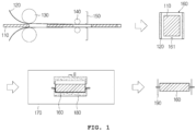
- FIG. 1 is a schematic view illustrating the manufacturing method of the graphite heat dissipation sheet according to an embodiment of the present disclosure
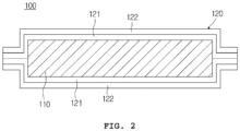
- FIG. 2 is a cross-sectional view illustrating a configuration relationship of the graphite heat dissipation sheet manufactured by the manufacturing method illustrated in FIG. 1 .
- the manufacturing method of the graphite heat dissipation sheet of the embodiment includes: a first process in which a graphite sheet 110 having a predetermined breadth is disposed between a pair of protective films 120 having inner side surfaces provided with thermal fusion layers 121 and both side surfaces of the pair of protective films 120 are thermally fused so that both side surfaces of the graphite sheet 110 are sealed; a second process in which an inner portion of the graphite sheet 110 having both sealed side surfaces thereof is vacuum-evacuated, opening parts of the pair of protective films 120 are thermally fused so that the graphite sheet 110 is entirely sealed, and then heat is applied to surfaces of the pair of protective films 120 such that the surfaces of the pair of protective films 120 are thermally fused with the graphite sheet 110; and a third process in which a border part of the graphite sheet 110 is cut.
- the pair of protective films 120 is continuously supplied from a film supply roll 130 that constitutes a film supply mechanism. Furthermore, the first process may include a process in which both side surfaces of the pair of protective films 120 are thermally fused so that both side surfaces of the graphite sheet 110 are sealed and a process in which the pair of protective films 120 is cut to a length capable of sufficiently covering the graphite sheet 110 when the graphite sheet 110 is input between the pair of protective films 120.
- the graphite sheet 110 is formed by pressing or rolling graphite powder to a predetermined thickness and a predetermined such that the graphite sheet 110 has a predetermined breadth, and natural graphite, artificial graphite, or a mixture thereof may be used for forming the graphite sheet 110.
- the graphite sheet 110 of the embodiment may be formed by mixing 80 wt% to 95 wt% of natural graphite and 5 wt% to 20 wt% of artificial graphite 5 to 20% by weight.
- natural graphite is foamed graphite, and foamed graphite is obtained by pulverizing natural graphite into powder and then performing sulfuric acid immersion, neutralization washing, and heating at high-temperature for foaming.
- a mixture in which foamed graphite having a diameter of 30 ⁇ m to 50 ⁇ m and foamed graphite having a diameter of 200 ⁇ m to 250 ⁇ m are mixed with each other with a predetermined ratio may be used.
- artificial graphite artificial graphite having a diameter of 20 ⁇ m to 80 ⁇ m may be used.
- the graphite sheet 110 of the embodiment may be formed of natural graphite and/or artificial graphite having the characteristics (the diameter and the composition ratio) as described above, but it is not necessary to limit the graphite sheet 110 to graphite having the limited characteristics described above.
- the graphite sheet 110 of the embodiment may be pressed such that the graphite sheet 110 has a density of 0.8 g/cm 3 to 1.65 g/cm 3 , but there is no limitation.
- the protective film 120 is formed of the thermal fusion layer 121 forming the inner side surface of the protective film 120, and is formed of a protective layer 122 forming an outer side surface of the protective film 120.
- the thermal fusion layer 121 may be formed of a material having a thermoplastic characteristic melting at a predetermined temperature, such as polyethylene (PE), cast polypropylene (CPP), low-density polyethylene (LDPE), linear low-density polyethylene (LLDPE), high-density polyethylene (HDPE), and so on. Meanwhile, it is preferable that a thickness of the thermal fusion layer 121 is less than 50 ⁇ m in order to minimize an effect on the thermal diffusion performance.
- the protective layer 122 serves to protect the graphite sheet 110 that will be positioned inside the protective layer 122, and may be formed of polyethylene terephthalate (PET), nylon (Ny), ethylene vinyl alcohol (EVOH), or the like.
- PET polyethylene terephthalate
- EVOH ethylene vinyl alcohol
- a thickness of the protective layer 122 is less than 20 ⁇ m in order to minimize an effect on the thermal diffusion performance.
- the pair of protective films 120 is continuously supplied by using a pair of film supply rolls 130.
- the film supply mechanism and the pair of film supply rolls 130 are configured on the basis of a configuration relationship generally used in the industry, and the pair of protective films 120 may be continuously supplied in a general manner.
- the pair of film supply rolls 130 is configured to supply the pair of protective films 120 in a state in which the pair of film supply rolls 130 is disposed to be vertically spaced apart from each other in a predetermined distance and, accordingly, a space into which the graphite sheet 110 is capable of being input is formed between the pair of protective films 120.
- the graphite sheet 110 is input into the space formed between the pair of protective films 120 supplied, is disposed between the pair of protective films 120, and is in a state in which the graphite sheet 110 is in close contact with the pair of protective films 120 by the pair of film supply rolls 130 and a pair of guide rolls 140 positioned in rear of the pair of film supply rolls 130.
- both side surfaces of the graphite sheet 110 are sealed by thermally fusing both side surfaces of the pair of protective films 120 between the pair of film supply rolls 130 and the pair of guide rolls 140.
- the thermal fusion of both side surfaces of the pair of protective films 120 is performed by heating the thermal fusion layers 121 forming the inner side surfaces of the pair of protective films 120 and bonding the thermal fusion layers 21, and may be performed by using a heating member (not illustrated) having a predetermined width. Then, as the pair of protective films 120 is cut to a length capable of sufficiently covering the graphite sheet 110 by using a cutting member 150 positioned in rear of the pair of guide rolls 140, a graphite heat dissipation member 160 having both side surfaces sealed by the pair of protective films 120 and having opening parts 161 at front and rear sides thereof or at upper and lower portions thereof is formed.
- the second process is a process in which the graphite sheet 110 is entirely sealed and the surfaces between the pair of protective films 120 and the graphite sheet 110 are thermally fused.
- the vacuum chamber 170 is a vacuum chamber generally used in the industry, and the vacuum chamber 170 is configured such that the vacuum chamber 170 vacuum-evacuates the inner portion of the graphite heat dissipation member 160 and the vacuum chamber 170 has a vacuum pressure capable of vacuum-evacuating and removing a gas and moisture remaining inside the graphite sheet 110.
- the vertical heating member 180 is configured as a hot press machine having a mold shape surrounding upper and lower surfaces and a border of the graphite heat dissipation member 160, and is configured to bonding the opening parts 161 of the opening parts of the graphite heat dissipation sheet 160 by thermal fusion and is configured to integrate the surfaces between the pair of protective films 120 and the graphite sheet 110 by thermal fusion.
- the graphite heat dissipation member 160 is input into the vacuum chamber 170 described above and the graphite heat dissipation member 160 is depressurized under vacuum for the predetermined time and then is heated and pressed so that the inner portion of the graphite heat dissipation member 160 is vacuum-evacuated, and the process in which the opening parts 161 of the graphite heat dissipation member 160 are bonded by thermal fusion is performed first, a process in which the graphite heat dissipation member 160 is input in a high-temperature chamber having a temperature at least 110 degrees Celsius and is heated such that the surfaces between the pair of protective films 120 and the graphite sheet 110 are thermally fused may be performed.
- the thermal fusion of the opening parts 161 of the graphite heat dissipation member 160 is performed by heating the thermal fusion layers 121 forming the inner side surfaces of the pair of protective films 120 and bonding the thermal fusion layers 21, and may be performed by using a heating member (not illustrated) having a predetermined width.
- the third process is a process of completing a graphite heat dissipation sheet 100 by cutting an unnecessary part of a border part of the graphite heat dissipation member 160 by using a cutting mechanism 190.
- the cutting mechanism 190 is configured on the basis of a configuration relationship generally used in the industry, and is configured to cut and remove an unnecessary part of the border part of the graphite heat dissipation member 160.
- the border part of the final graphite heat dissipation sheet 100 is cut such that the border part of the final graphite heat dissipation sheet has a minimum bezel.
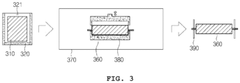
- FIG. 3 is a schematic view illustrating the manufacturing method of the graphite heat dissipation sheet according to another embodiment of the present disclosure.
- the manufacturing method of the graphite heat dissipation sheet according to another embodiment includes: a first process in which a graphite sheet 310 having a predetermined breadth is inserted into and disposed inside a film-type pouch (bag) 320 having an inner side surface provided with a thermal fusion layer and having a first side open; a second process in which an inner portion of the graphite sheet 310 is vacuum-evacuated by applying vacuum to the film-type pouch 320 having the first side open, the graphite sheet 310 is entirely sealed by thermally fusing an opening part 321 of the film-type pouch 320, and then heat is applied to a surface of the film-type pouch 320 so that the surface of the film-type pouch 320 and a surface of the graphite sheet 310 are thermally fused with each other; and a third process in which a border part
- the manufacturing method of the graphite heat dissipation sheet in this embodiment has the film-type pouch (bag) 320 having the inner side surface provided with the thermal fusion layer and having the first side open
- the final graphite heat dissipation sheet is formed by performing the first process, the second process, and the third process that are similar to the manufacturing method illustrated in FIG. 1 , so that the description thereof will be omitted.
- the reference numeral 360 refers to a graphite heat dissipation member
- the reference numeral 370 refers to a vacuum chamber
- the reference numeral 380 refers to a vertical heating member
- the reference numeral 390 refers to a cutting mechanism.
- the graphite sheet is covered with the protective film or the pouch having the inner side surface provided with the thermal fusion layer, the inner portion of the graphite sheet is vacuum-evacuated so that a gas and moisture remaining inside the graphite sheet are removed, heat is applied to the thermal fusion layer so that the fusion effect between the graphite sheet and the protective film or between the graphite sheet and the surface of the pouch is realized, and the pressing effect due to the pressure difference by vacuum is added, so that the graphite heat dissipation sheet in which the protective film and the graphite sheet or the pouch and the graphite sheet are more solidly integrated with each other is capable of being manufactured.
- the graphite heat dissipation sheet of the present disclosure is capable of being configured as a thin film, has excellent heat dissipation performance, and is capable of being conveniently attached to and used at a heat generation area of an electronic device (a TV and so on).
Landscapes
- Engineering & Computer Science (AREA)
- Physics & Mathematics (AREA)
- Ceramic Engineering (AREA)
- Thermal Sciences (AREA)
- Microelectronics & Electronic Packaging (AREA)
- Fluid Mechanics (AREA)
- Quality & Reliability (AREA)
- Chemical & Material Sciences (AREA)
- Mechanical Engineering (AREA)
- General Engineering & Computer Science (AREA)
- Cooling Or The Like Of Semiconductors Or Solid State Devices (AREA)
- Carbon And Carbon Compounds (AREA)
- Lining Or Joining Of Plastics Or The Like (AREA)
- Cooling Or The Like Of Electrical Apparatus (AREA)
- Laminated Bodies (AREA)
Abstract
Description
- The present disclosure relates to a manufacturing method of a graphite heat dissipation sheet. More particularly, the present disclosure relates to a manufacturing method of a graphite heat dissipation sheet, in which a graphite sheet is covered with a film or a pouch having an inner side surface provided with a thermal fusion layer and an inner portion of the graphite sheet is vacuum-evacuated so that a gas and moisture remaining inside the graphite sheet are removed, heat is applied to the thermal fusion layer so that a fusion effect between the graphite sheet and a surface of the film or between the graphite sheet and a surface of the pouch is realized, and that a pressing effect due to a pressure difference by vacuum is added, thereby being capable of manufacturing the graphite heat dissipation sheet in which the film and the graphite sheet or the pouch and the graphite sheet are more solidly integrated with each other.
- Recently, as electronic devices have been highly integrated and become thinner at a rapid pace, the performance of chips and so on mounted in such devices has been reinforced. This trend is spreading to not only electric/electronic devices but also automobiles, medical devices, and so on. As the chips used in electronic devices are highly integrated, more heat is generated, thereby causing many problems such as deterioration in the performance of the electronic devices, malfunction of their peripheral devices, thermal degradation of their substrates, and so on.
- Particularly, a thinner heat dissipation material is required for an electronic device (a TV and so on) that employs an LED, an OLED, or the like. In this regard, a substrate on which an IC chip is mounted is made of a metal printed circuit board (PCB) having good thermal conductivity, or a heat sink made of aluminum is used to thereby control heat. In addition, a thermally conductive thin film such as a natural graphite thin film and a synthetic graphite thin film that employs a carbon-based material, a copper plate, and so on are mainly used for controlling heat in electronic devices and so on.
- Meanwhile, in a heat dissipation sheet that employs natural graphite and/or synthetic graphite is capable of being configured as a thin film, has excellent heat dissipation performance, and is capable of being attached to and used in a heat generation region of an electronic device (a TV and so on), so that extensive research on such a heat dissipation sheet has been conducted.
- Such a graphite heat dissipation sheet described above is generally manufactured in a sheet shape by rolling foamed graphite particles, and there is a disadvantage that dusts are generated and has high brittleness. In order to compensate for such structural disadvantages and to attach the graphite heat dissipation sheet to a subject of application, as mentioned in
Korean Patent No. 10-1509494 - Meanwhile, since the graphite sheet has a layered structure due to rolling manufacturing, residual gas and moisture exist inside the graphite sheet, which causes the generation of bubbles after laminating. In addition, during laminating, when foreign substances are present on a surface of the graphite sheet, air bubbles may occur, and there is a disadvantage that the protective films may be delaminated since the adhesive force between the protective films in a border part is weak.
- Accordingly, the present disclosure has been made keeping in mind the above problems occurring in the related art, and an objective of the present disclosure is to provide a manufacturing method of a graphite heat dissipation sheet, the manufacturing method being configured such that a graphite sheet is covered with a film or a pouch having an inner side surface provided with a thermal fusion layer and an inner portion of the graphite sheet is vacuum-evacuated so that a gas and moisture remaining inside the graphite sheet are removed, heat is applied to the thermal fusion layer so that a fusion effect between the graphite sheet and a surface of the film or between the graphite sheet and a surface of the pouch is realized, and that a pressing effect due to a pressure difference by vacuum is added, thereby being capable of manufacturing the graphite heat dissipation sheet in which the film and the graphite sheet or the pouch and the graphite sheet are more solidly integrated with each other.
- In order to achieve the objective described above, according to the present disclosure, there is provided a manufacturing method of a graphite heat dissipation sheet, the manufacturing method including: a first process in which a graphite sheet having a predetermined width is disposed between a pair of films having inner side surfaces provided with thermal fusion layers that have a thermoplastic characteristic that causes the thermal fusion layers to melt at a predetermined temperature and in which both side surfaces of the pair of films are thermally fused, thereby sealing both side surfaces of the graphite sheet; a second process in which an inner portion of the graphite sheet having both sealed side surfaces thereof is vacuum-evacuated, opening parts of the pair of films are thermally fused so that the graphite sheet is entirely sealed, and then heat is applied to surfaces of the pair of films such that the thermal fusion layers are melted so that the graphite sheet and the surfaces of the pair of films are thermally fused; and a third process in which a border part of the graphite sheet is cut.
- The fist process may include a process in which both side surfaces of the pair of films are thermally fused so that both side surfaces of the graphite sheet are sealed when the pair of films are continuously supplied from a film supply mechanism and the graphite sheet is input between the pair of films, and may include a process in which the pair of films is cut to a length capable of sufficiently covering the graphite sheet.
- In the second process, it is preferable that the vacuum-evacuation, the thermal fusion of the opening parts, and the thermal fusion of the surfaces of the pair of films are performed simultaneously in a vacuum chamber by inputting the graphite sheet having both sealed side surfaces in the vacuum chamber and depressurizing the graphite sheet under vacuum for a predetermined time and then pressing the graphite sheet with a vertical heating member.
- Meanwhile, the second process may include a process in which the graphite sheet having both sealed side surfaces is input in a vacuum chamber and is depressurized under vacuum for a predetermined time and then is heated and pressed so that the vacuum-evacuation is performed and the opening parts are thermally fused, and may include a process in which the graphite sheet is input in a high-temperature chamber and is heated so that the surfaces of the pair of films and the graphite sheet are thermally fused with each other.
- In addition, in order to achieve the objective described above, according to the present disclosure, there is provided a manufacturing method of a graphite heat dissipation sheet, the manufacturing method including: a first process in which a graphite sheet having a predetermined width is inserted into and disposed inside a film-type pouch which has an inner side surface provided with a thermal fusion layer with a thermoplastic characteristic that causes the thermal fusion layer to melt at a predetermined temperature and which has a first side open; a second process in which an inner portion of the graphite sheet is vacuum-evacuated by applying vacuum to the film-type pouch having the first side open, thermally fusing an opening part of the film-type pouch so that the graphite sheet is entirely sealed, and applying heat to a surface of the film-type pouch such that the thermal fusion layer is melt so that the graphite sheet and the surface of the film-type pouch are thermally fused with each other; and a third process in which a border part of the graphite sheet is cut.
- In the second process, it is preferable that the vacuum-evacuation, the thermal fusion of the opening part, and the thermal fusion of the surface of the film-type pouch are performed simultaneously in a vacuum chamber by inputting the film-type pouch having the graphite sheet disposed in an inner portion of the film-type pouch in the vacuum chamber and depressurizing the film-type pouch under vacuum for a predetermined time and then pressing the film-type pouch with a vertical heating member.
- Meanwhile, the second process may include a process in which the film-type pouch having the graphite sheet disposed in an inner portion of the film-type pouch is input in a vacuum chamber and is depressurized under vacuum for a predetermined time and then is heated and pressed so that the vacuum-evacuation is performed and the opening part is thermally fused, and may include a process in which the film-type pouch is input in a high-temperature chamber and is heated so that the surface of the film-type pouch and the graphite sheet are thermally fused with each other.
- In the manufacturing method of the graphite heat dissipation sheet of the present disclosure, the graphite sheet is covered with the film or the pouch that are having the inner side surface thereof provided with the thermal fusion layer, the inner portion of the graphite sheet is vacuum-evacuated so that a gas and moisture remaining inside the graphite sheet are removed, heat is applied to the thermal fusion layer so that the fusion effect between the graphite sheet and the film or between the graphite sheet and the surface of the pouch is realized, and the pressing effect due to the pressure difference by vacuum is added, so that there is an advantage that the graphite heat dissipation sheet in which the film and the graphite sheet or the pouch and the graphite sheet are more solidly integrated with each other is capable of being manufactured.
-
-
FIG. 1 is a schematic view illustrating a manufacturing method of a graphite heat dissipation sheet according to an embodiment of the present disclosure, -
FIG. 2 is a cross-sectional view illustrating a configuration relationship of the graphite heat dissipation sheet manufactured by the manufacturing method illustrated inFIG. 1 , and -
FIG. 3 is a schematic view illustrating the manufacturing method of the graphite heat dissipation sheet according to another embodiment of the present disclosure. - Hereinafter, an exemplary embodiment of a manufacturing method of a graphite heat dissipation sheet according to the present disclosure will be described in detail with reference to the accompanying drawings. The present disclosure is not limited to the embodiments disclosed below, but may be implemented in various different forms. The present embodiments are provided so that the present disclosure will be thorough and complete, and will fully convey the scope of the present disclosure to those skilled in the art.
-
FIG. 1 is a schematic view illustrating the manufacturing method of the graphite heat dissipation sheet according to an embodiment of the present disclosure, andFIG. 2 is a cross-sectional view illustrating a configuration relationship of the graphite heat dissipation sheet manufactured by the manufacturing method illustrated inFIG. 1 . - As illustrated in
FIG. 1 andFIG. 2 , the manufacturing method of the graphite heat dissipation sheet of the embodiment includes: a first process in which agraphite sheet 110 having a predetermined breadth is disposed between a pair ofprotective films 120 having inner side surfaces provided withthermal fusion layers 121 and both side surfaces of the pair ofprotective films 120 are thermally fused so that both side surfaces of thegraphite sheet 110 are sealed; a second process in which an inner portion of thegraphite sheet 110 having both sealed side surfaces thereof is vacuum-evacuated, opening parts of the pair ofprotective films 120 are thermally fused so that thegraphite sheet 110 is entirely sealed, and then heat is applied to surfaces of the pair ofprotective films 120 such that the surfaces of the pair ofprotective films 120 are thermally fused with thegraphite sheet 110; and a third process in which a border part of thegraphite sheet 110 is cut. - In the first process, the pair of
protective films 120 is continuously supplied from afilm supply roll 130 that constitutes a film supply mechanism. Furthermore, the first process may include a process in which both side surfaces of the pair ofprotective films 120 are thermally fused so that both side surfaces of thegraphite sheet 110 are sealed and a process in which the pair ofprotective films 120 is cut to a length capable of sufficiently covering thegraphite sheet 110 when thegraphite sheet 110 is input between the pair ofprotective films 120. - The
graphite sheet 110 is formed by pressing or rolling graphite powder to a predetermined thickness and a predetermined such that thegraphite sheet 110 has a predetermined breadth, and natural graphite, artificial graphite, or a mixture thereof may be used for forming thegraphite sheet 110. For example, thegraphite sheet 110 of the embodiment may be formed by mixing 80 wt% to 95 wt% of natural graphite and 5 wt% to 20 wt% of artificial graphite 5 to 20% by weight. Here, natural graphite is foamed graphite, and foamed graphite is obtained by pulverizing natural graphite into powder and then performing sulfuric acid immersion, neutralization washing, and heating at high-temperature for foaming. As natural graphite of the embodiment, a mixture in which foamed graphite having a diameter of 30 µm to 50 µm and foamed graphite having a diameter of 200 µm to 250 µm are mixed with each other with a predetermined ratio may be used. Furthermore, as artificial graphite, artificial graphite having a diameter of 20 µm to 80 µm may be used. - That is, the
graphite sheet 110 of the embodiment may be formed of natural graphite and/or artificial graphite having the characteristics (the diameter and the composition ratio) as described above, but it is not necessary to limit thegraphite sheet 110 to graphite having the limited characteristics described above. In addition, thegraphite sheet 110 of the embodiment may be pressed such that thegraphite sheet 110 has a density of 0.8 g/cm3 to 1.65 g/cm3, but there is no limitation. - The
graphite sheet 110 as described above contains fine amounts of gas within graphite, and has a porous structure so that pores are formed in thegraphite sheet 110 even when thegraphite sheet 110 is pressed or rolled such that thegraphite sheet 110 has the predetermined density. Furthermore, a gas such as sulfuric acid gas generated during the manufacturing process of thegraphite sheet 110 and moisture in the atmosphere are inevitably contained in the pores. - The
protective film 120 is formed of thethermal fusion layer 121 forming the inner side surface of theprotective film 120, and is formed of aprotective layer 122 forming an outer side surface of theprotective film 120. Here, thethermal fusion layer 121 may be formed of a material having a thermoplastic characteristic melting at a predetermined temperature, such as polyethylene (PE), cast polypropylene (CPP), low-density polyethylene (LDPE), linear low-density polyethylene (LLDPE), high-density polyethylene (HDPE), and so on. Meanwhile, it is preferable that a thickness of thethermal fusion layer 121 is less than 50 µm in order to minimize an effect on the thermal diffusion performance. Theprotective layer 122 serves to protect thegraphite sheet 110 that will be positioned inside theprotective layer 122, and may be formed of polyethylene terephthalate (PET), nylon (Ny), ethylene vinyl alcohol (EVOH), or the like. Here, it is preferable that a thickness of theprotective layer 122 is less than 20 µm in order to minimize an effect on the thermal diffusion performance. - In performing the first process by using the
graphite sheet 110 and the pair ofprotective films 120 as described above, the pair ofprotective films 120 is continuously supplied by using a pair offilm supply rolls 130. Here, the film supply mechanism and the pair offilm supply rolls 130 are configured on the basis of a configuration relationship generally used in the industry, and the pair ofprotective films 120 may be continuously supplied in a general manner. At this time, the pair offilm supply rolls 130 is configured to supply the pair ofprotective films 120 in a state in which the pair offilm supply rolls 130 is disposed to be vertically spaced apart from each other in a predetermined distance and, accordingly, a space into which thegraphite sheet 110 is capable of being input is formed between the pair ofprotective films 120. - Therefore, the
graphite sheet 110 is input into the space formed between the pair ofprotective films 120 supplied, is disposed between the pair ofprotective films 120, and is in a state in which thegraphite sheet 110 is in close contact with the pair ofprotective films 120 by the pair offilm supply rolls 130 and a pair ofguide rolls 140 positioned in rear of the pair offilm supply rolls 130. In such agraphite sheet 110, both side surfaces of thegraphite sheet 110 are sealed by thermally fusing both side surfaces of the pair ofprotective films 120 between the pair offilm supply rolls 130 and the pair ofguide rolls 140. At this time, the thermal fusion of both side surfaces of the pair ofprotective films 120 is performed by heating thethermal fusion layers 121 forming the inner side surfaces of the pair ofprotective films 120 and bonding the thermal fusion layers 21, and may be performed by using a heating member (not illustrated) having a predetermined width. Then, as the pair ofprotective films 120 is cut to a length capable of sufficiently covering thegraphite sheet 110 by using acutting member 150 positioned in rear of the pair ofguide rolls 140, a graphiteheat dissipation member 160 having both side surfaces sealed by the pair ofprotective films 120 and havingopening parts 161 at front and rear sides thereof or at upper and lower portions thereof is formed. - The second process is a process in which the
graphite sheet 110 is entirely sealed and the surfaces between the pair ofprotective films 120 and thegraphite sheet 110 are thermally fused. In the second process, a process in which the graphiteheat dissipation member 160 is input into avacuum chamber 170 and the graphiteheat dissipation member 160 is depressurized under vacuum for a predetermined time and then is pressed by avertical heating member 180 so that an inner portion of the graphiteheat dissipation member 160 is vacuum-evacuated, a process in which theopening parts 161 of the graphiteheat dissipation member 160 are bonded to each other by thermal fusion, and a process in which the surfaces between the pair ofprotective films 120 and thegraphite sheet 110 are thermally fused are performed simultaneously in thevacuum chamber 170. - Here, the
vacuum chamber 170 is a vacuum chamber generally used in the industry, and thevacuum chamber 170 is configured such that thevacuum chamber 170 vacuum-evacuates the inner portion of the graphiteheat dissipation member 160 and thevacuum chamber 170 has a vacuum pressure capable of vacuum-evacuating and removing a gas and moisture remaining inside thegraphite sheet 110. In addition, thevertical heating member 180 is configured as a hot press machine having a mold shape surrounding upper and lower surfaces and a border of the graphiteheat dissipation member 160, and is configured to bonding theopening parts 161 of the opening parts of the graphiteheat dissipation sheet 160 by thermal fusion and is configured to integrate the surfaces between the pair ofprotective films 120 and thegraphite sheet 110 by thermal fusion. As such, in the second process, heat is applied to the thermal fusion layers 121 formed on the inner side surfaces of theprotective films 120 so that an effect in which the surfaces between thegraphite sheet 110 and the pair ofprotective films 120 are fused in a molten state is realized, and a pressing effect by a pressure difference due to vacuum is added, so that the pair ofprotective films 120 and thegraphite sheet 110 are more solidly integrated with each other. - Meanwhile, in the second process, after the process in which the graphite
heat dissipation member 160 is input into thevacuum chamber 170 described above and the graphiteheat dissipation member 160 is depressurized under vacuum for the predetermined time and then is heated and pressed so that the inner portion of the graphiteheat dissipation member 160 is vacuum-evacuated, and the process in which the openingparts 161 of the graphiteheat dissipation member 160 are bonded by thermal fusion is performed first, a process in which the graphiteheat dissipation member 160 is input in a high-temperature chamber having a temperature at least 110 degrees Celsius and is heated such that the surfaces between the pair ofprotective films 120 and thegraphite sheet 110 are thermally fused may be performed. Here, the thermal fusion of the openingparts 161 of the graphiteheat dissipation member 160 is performed by heating the thermal fusion layers 121 forming the inner side surfaces of the pair ofprotective films 120 and bonding the thermal fusion layers 21, and may be performed by using a heating member (not illustrated) having a predetermined width. - The third process is a process of completing a graphite
heat dissipation sheet 100 by cutting an unnecessary part of a border part of the graphiteheat dissipation member 160 by using acutting mechanism 190. Here, thecutting mechanism 190 is configured on the basis of a configuration relationship generally used in the industry, and is configured to cut and remove an unnecessary part of the border part of the graphiteheat dissipation member 160. At this time, it is preferable that the border part of the final graphiteheat dissipation sheet 100 is cut such that the border part of the final graphite heat dissipation sheet has a minimum bezel. -
FIG. 3 is a schematic view illustrating the manufacturing method of the graphite heat dissipation sheet according to another embodiment of the present disclosure. As illustrated inFIG. 3 , the manufacturing method of the graphite heat dissipation sheet according to another embodiment includes: a first process in which agraphite sheet 310 having a predetermined breadth is inserted into and disposed inside a film-type pouch (bag) 320 having an inner side surface provided with a thermal fusion layer and having a first side open; a second process in which an inner portion of thegraphite sheet 310 is vacuum-evacuated by applying vacuum to the film-type pouch 320 having the first side open, thegraphite sheet 310 is entirely sealed by thermally fusing anopening part 321 of the film-type pouch 320, and then heat is applied to a surface of the film-type pouch 320 so that the surface of the film-type pouch 320 and a surface of thegraphite sheet 310 are thermally fused with each other; and a third process in which a border part of thegraphite sheet 310 is cut. In the film-type pouch 320 of this embodiment, it is preferable that three surfaces of a film of the film-type pouch 320 are sealed by thermal fusion. - Except that the manufacturing method of the graphite heat dissipation sheet in this embodiment has the film-type pouch (bag) 320 having the inner side surface provided with the thermal fusion layer and having the first side open, the final graphite heat dissipation sheet is formed by performing the first process, the second process, and the third process that are similar to the manufacturing method illustrated in
FIG. 1 , so that the description thereof will be omitted. InFIG. 3 , thereference numeral 360 refers to a graphite heat dissipation member, thereference numeral 370 refers to a vacuum chamber, thereference numeral 380 refers to a vertical heating member, and thereference numeral 390 refers to a cutting mechanism. - In the manufacturing method of the graphite heat dissipation sheet of the present disclosure, the graphite sheet is covered with the protective film or the pouch having the inner side surface provided with the thermal fusion layer, the inner portion of the graphite sheet is vacuum-evacuated so that a gas and moisture remaining inside the graphite sheet are removed, heat is applied to the thermal fusion layer so that the fusion effect between the graphite sheet and the protective film or between the graphite sheet and the surface of the pouch is realized, and the pressing effect due to the pressure difference by vacuum is added, so that the graphite heat dissipation sheet in which the protective film and the graphite sheet or the pouch and the graphite sheet are more solidly integrated with each other is capable of being manufactured.
- The features of the manufacturing method of the graphite heat dissipation sheet of the present disclosure have been described above with reference to the accompanying drawings, but they are just preferable examples. Therefore, it is apparent to those skilled in the art that the present disclosure is not limited to the embodiments and may be modified in various ways without departing from the spirit and scope of the present disclosure, so it should be understood that those modifications and changes are included in claims of the present disclosure.
- The graphite heat dissipation sheet of the present disclosure is capable of being configured as a thin film, has excellent heat dissipation performance, and is capable of being conveniently attached to and used at a heat generation area of an electronic device (a TV and so on).
Claims (7)
- A manufacturing method of a graphite heat dissipation sheet, the manufacturing method comprising:a first process in which a graphite sheet having a predetermined width is disposed between a pair of films having inner side surfaces provided with thermal fusion layers that have a thermoplastic characteristic that causes the thermal fusion layers to melt at a predetermined temperature and in which both side surfaces of the pair of films are thermally fused, thereby sealing both side surfaces of the graphite sheet;a second process in which an inner portion of the graphite sheet having both sealed side surfaces thereof is vacuum-evacuated, opening parts of the pair of films are thermally fused so that the graphite sheet is entirely sealed, and then heat is applied to surfaces of the pair of films such that the thermal fusion layers are melted so that the graphite sheet and the surfaces of the pair of films are thermally fused; anda third process in which a border part of the graphite sheet is cut.
- The manufacturing method of claim 1, wherein the fist process comprises a process in which both side surfaces of the pair of films are thermally fused so that both side surfaces of the graphite sheet are sealed when the pair of films are continuously supplied from a film supply mechanism and the graphite sheet is input between the pair of films, and comprises a process in which the pair of films is cut to a length capable of sufficiently covering the graphite sheet.
- The manufacturing method of claim 1 or claim 2, wherein, in the second process, the vacuum-evacuation, the thermal fusion of the opening parts, and the thermal fusion of the surfaces of the pair of films are performed simultaneously in a vacuum chamber by inputting the graphite sheet having both sealed side surfaces in the vacuum chamber and depressurizing the graphite sheet under vacuum for a predetermined time and then pressing the graphite sheet with a vertical heating member.
- The manufacturing method of claim 1 or claim 2, wherein the second process comprises a process in which the graphite sheet having both sealed side surfaces is input in a vacuum chamber and is depressurized under vacuum for a predetermined time and then is heated and pressed so that the vacuum-evacuation is performed and the opening parts are thermally fused, and comprises a process in which the graphite sheet is input in a high-temperature chamber and is heated so that the surfaces of the pair of films and the graphite sheet are thermally fused with each other.
- A manufacturing method of a graphite heat dissipation sheet, the manufacturing method comprising:a first process in which a graphite sheet having a predetermined width is inserted into and disposed inside a film-type pouch which has an inner side surface provided with a thermal fusion layer with a thermoplastic characteristic that causes the thermal fusion layer to melt at a predetermined temperature and which has a first side open;a second process in which an inner portion of the graphite sheet is vacuum-evacuated by applying vacuum to the film-type pouch having the first side open, thermally fusing an opening part of the film-type pouch so that the graphite sheet is entirely sealed, and applying heat to a surface of the film-type pouch such that the thermal fusion layer is melt so that the graphite sheet and the surface of the film-type pouch are thermally fused with each other; anda third process in which a border part of the graphite sheet is cut.
- The manufacturing method of claim 5, wherein, in the second process, the vacuum-evacuation, the thermal fusion of the opening part, and the thermal fusion of the surface of the film-type pouch are performed simultaneously in a vacuum chamber by inputting the film-type pouch having the graphite sheet disposed in an inner portion of the film-type pouch in the vacuum chamber and depressurizing the film-type pouch under vacuum for a predetermined time and then pressing the film-type pouch with a vertical heating member.
- The manufacturing method of claim 5, wherein the second process comprises a process in which the film-type pouch having the graphite sheet disposed in an inner portion of the film-type pouch is input in a vacuum chamber and is depressurized under vacuum for a predetermined time and then is heated and pressed so that the vacuum-evacuation is performed and the opening part is thermally fused, and comprises a process in which the film-type pouch is input in a high-temperature chamber and is heated so that the surface of the film-type pouch and the graphite sheet are thermally fused with each other.
Applications Claiming Priority (2)
| Application Number | Priority Date | Filing Date | Title |
|---|---|---|---|
| KR1020230088215A KR102659476B1 (en) | 2023-07-07 | 2023-07-07 | Manufacturing method of graphite heat dissipation sheet |
| PCT/KR2024/003394 WO2025014025A1 (en) | 2023-07-07 | 2024-03-19 | Method for manufacturing graphite heat dissipation sheet |
Publications (2)
| Publication Number | Publication Date |
|---|---|
| EP4565021A1 true EP4565021A1 (en) | 2025-06-04 |
| EP4565021A4 EP4565021A4 (en) | 2026-04-29 |
Family
ID=90881391
Family Applications (1)
| Application Number | Title | Priority Date | Filing Date |
|---|---|---|---|
| EP24839846.3A Withdrawn EP4565021A4 (en) | 2023-07-07 | 2024-03-19 | METHOD FOR PRODUCING A GRAPHITE HEAT DISPENSING FILM |
Country Status (6)
| Country | Link |
|---|---|
| US (1) | US20260184057A1 (en) |
| EP (1) | EP4565021A4 (en) |
| JP (1) | JP2025538668A (en) |
| KR (1) | KR102659476B1 (en) |
| CN (1) | CN119586336A (en) |
| WO (1) | WO2025014025A1 (en) |
Family Cites Families (13)
| Publication number | Priority date | Publication date | Assignee | Title |
|---|---|---|---|---|
| KR20050038072A (en) * | 2003-10-21 | 2005-04-27 | 충남대학교산학협력단 | Vacuum insulation panel and method thereof |
| TWI263403B (en) * | 2004-01-22 | 2006-10-01 | Murata Manufacturing Co | Electronic component manufacturing method |
| JP2006188022A (en) * | 2005-01-07 | 2006-07-20 | Taisei Laminator Co Ltd | Carbon graphite sheet |
| JP2007155135A (en) * | 2005-04-27 | 2007-06-21 | Nisshinbo Ind Inc | Vacuum heat insulating material and manufacturing method thereof |
| JP5089233B2 (en) * | 2007-04-26 | 2012-12-05 | 株式会社カネカ | Graphite composite film |
| JP5048166B2 (en) * | 2010-02-22 | 2012-10-17 | 株式会社カネカ | Manufacturing method and rewinding method of graphite film, and manufacturing method of graphite composite film and graphite-extracted processed product |
| KR101509494B1 (en) | 2013-08-30 | 2015-04-08 | 주식회사 서환이지 | Heat dissipation sheet using graphite for electronic device |
| JP6431409B2 (en) * | 2015-03-05 | 2018-11-28 | 株式会社フジクラ | Method for manufacturing power storage element |
| JP2022166335A (en) * | 2019-09-26 | 2022-11-02 | Agc株式会社 | Method for manufacturing heat insulating member |
| KR102148670B1 (en) | 2020-02-28 | 2020-08-27 | 유성운 | Manufacturing method of bezel-less heat-conductive graphite sheet |
| KR20220000393U (en) * | 2020-08-06 | 2022-02-15 | 자화전자(주) | Heat spreading sheet and electronic equipment having the same |
| KR20230030692A (en) * | 2021-08-25 | 2023-03-07 | 삼성디스플레이 주식회사 | Panel bottom sheet and display device comprising the same |
| KR102448949B1 (en) | 2022-04-28 | 2022-09-30 | 인동첨단소재(주) | Manufacturing method of heat-conductive graphite sheet for display panel |
-
2023
- 2023-07-07 KR KR1020230088215A patent/KR102659476B1/en active Active
-
2024
- 2024-03-19 CN CN202480002180.9A patent/CN119586336A/en active Pending
- 2024-03-19 EP EP24839846.3A patent/EP4565021A4/en not_active Withdrawn
- 2024-03-19 WO PCT/KR2024/003394 patent/WO2025014025A1/en not_active Ceased
- 2024-03-19 US US18/859,335 patent/US20260184057A1/en active Pending
- 2024-03-19 JP JP2025531038A patent/JP2025538668A/en active Pending
Also Published As
| Publication number | Publication date |
|---|---|
| KR102659476B1 (en) | 2024-04-22 |
| CN119586336A (en) | 2025-03-07 |
| WO2025014025A1 (en) | 2025-01-16 |
| US20260184057A1 (en) | 2026-07-02 |
| EP4565021A4 (en) | 2026-04-29 |
| JP2025538668A (en) | 2025-11-28 |
Similar Documents
| Publication | Publication Date | Title |
|---|---|---|
| JP6863523B2 (en) | Manufacturing method of release film and molded product | |
| JP6939730B2 (en) | Manufacturing method of release film and flexible printed circuit board | |
| CN105102224B (en) | Film and tape label plastic containers | |
| TWI613090B (en) | Laminated body and its construction method | |
| WO2014154130A1 (en) | In-mould label and labeled plastic container using same | |
| CN118302294B (en) | Mold release film and method for producing molded article | |
| WO2014141512A1 (en) | Release film | |
| JP5683096B2 (en) | Method for reducing the amount of electrification of carrier tape | |
| TW201105487A (en) | Embossed carrier tape and method for producing the same | |
| JP2020167212A (en) | Release film for printed wiring board manufacturing process and its applications | |
| WO2019069656A1 (en) | Multilayer releasing film, method for producing multilayer releasing film, and method for producing flexible printed circuit | |
| TW201420339A (en) | Base material sheet for packing electronic parts, multilayered sheet for packing electronic parts, carrier tape for packing electronic parts, and carrier of electronic parts | |
| JP2009113383A (en) | Method and apparatus for manufacturing plastic hollow plate | |
| JP2002079630A (en) | Mold release multilayered film and cover lay molding method | |
| CN101152775A (en) | Method for making thermoformed articles | |
| JP2008155956A (en) | Solid packaging | |
| KR102659476B1 (en) | Manufacturing method of graphite heat dissipation sheet | |
| JP2023046646A (en) | Method for manufacturing release film and molded product | |
| JP2018154115A (en) | Decorative film and method for producing decorative molding using the same | |
| JP2000272055A (en) | Mold release type multilayer film | |
| JP7838693B1 (en) | Method for manufacturing release film and molded product | |
| JP7836505B2 (en) | Anti-fog multilayer films, laminates, packaging materials, lids, and top-seal containers | |
| JP2006212954A (en) | Mold release film | |
| CN111448273A (en) | Separator and adhesive tape or sheet with separator | |
| JP2003236700A (en) | Press ram for laminating press |
Legal Events
| Date | Code | Title | Description |
|---|---|---|---|
| STAA | Information on the status of an ep patent application or granted ep patent |
Free format text: STATUS: THE INTERNATIONAL PUBLICATION HAS BEEN MADE |
|
| PUAI | Public reference made under article 153(3) epc to a published international application that has entered the european phase |
Free format text: ORIGINAL CODE: 0009012 |
|
| STAA | Information on the status of an ep patent application or granted ep patent |
Free format text: STATUS: REQUEST FOR EXAMINATION WAS MADE |
|
| 17P | Request for examination filed |
Effective date: 20250225 |
|
| AK | Designated contracting states |
Kind code of ref document: A1 Designated state(s): AL AT BE BG CH CY CZ DE DK EE ES FI FR GB GR HR HU IE IS IT LI LT LU LV MC ME MK MT NL NO PL PT RO RS SE SI SK SM TR |
|
| REG | Reference to a national code |
Ref country code: DE Ref legal event code: R079 Free format text: PREVIOUS MAIN CLASS: H05K0007200000 Ipc: H10W0040000000 |
|
| A4 | Supplementary search report drawn up and despatched |
Effective date: 20260331 |
|
| RIC1 | Information provided on ipc code assigned before grant |
Ipc: H10W 40/00 20260101AFI20260325BHEP Ipc: H10W 40/25 20260101ALI20260325BHEP Ipc: B32B 37/22 20060101ALI20260325BHEP Ipc: B32B 9/00 20060101ALI20260325BHEP Ipc: H05K 7/20 20060101ALI20260325BHEP |
|
| STAA | Information on the status of an ep patent application or granted ep patent |
Free format text: STATUS: THE APPLICATION HAS BEEN WITHDRAWN |
|
| 18W | Application withdrawn |
Effective date: 20260502 |