EP4564663A1 - Rotary flexible photovoltaic support - Google Patents
Rotary flexible photovoltaic support Download PDFInfo
- Publication number
- EP4564663A1 EP4564663A1 EP22934562.4A EP22934562A EP4564663A1 EP 4564663 A1 EP4564663 A1 EP 4564663A1 EP 22934562 A EP22934562 A EP 22934562A EP 4564663 A1 EP4564663 A1 EP 4564663A1
- Authority
- EP
- European Patent Office
- Prior art keywords
- connecting pieces
- columns
- column
- lifting rod
- spiral groove
- Prior art date
- Legal status (The legal status is an assumption and is not a legal conclusion. Google has not performed a legal analysis and makes no representation as to the accuracy of the status listed.)
- Pending
Links
Images




Classifications
-
- H—ELECTRICITY
- H02—GENERATION; CONVERSION OR DISTRIBUTION OF ELECTRIC POWER
- H02S—GENERATION OF ELECTRIC POWER BY CONVERSION OF INFRARED RADIATION, VISIBLE LIGHT OR ULTRAVIOLET LIGHT, e.g. USING PHOTOVOLTAIC [PV] MODULES
- H02S20/00—Supporting structures for PV modules
- H02S20/30—Supporting structures being movable or adjustable, e.g. for angle adjustment
-
- F—MECHANICAL ENGINEERING; LIGHTING; HEATING; WEAPONS; BLASTING
- F24—HEATING; RANGES; VENTILATING
- F24S—SOLAR HEAT COLLECTORS; SOLAR HEAT SYSTEMS
- F24S25/00—Arrangement of stationary mountings or supports for solar heat collector modules
- F24S25/50—Arrangement of stationary mountings or supports for solar heat collector modules comprising elongate non-rigid elements, e.g. straps, wires or ropes
-
- F—MECHANICAL ENGINEERING; LIGHTING; HEATING; WEAPONS; BLASTING
- F24—HEATING; RANGES; VENTILATING
- F24S—SOLAR HEAT COLLECTORS; SOLAR HEAT SYSTEMS
- F24S30/00—Arrangements for moving or orienting solar heat collector modules
- F24S30/40—Arrangements for moving or orienting solar heat collector modules for rotary movement
- F24S30/48—Arrangements for moving or orienting solar heat collector modules for rotary movement with three or more rotation axes or with multiple degrees of freedom
-
- H—ELECTRICITY
- H02—GENERATION; CONVERSION OR DISTRIBUTION OF ELECTRIC POWER
- H02S—GENERATION OF ELECTRIC POWER BY CONVERSION OF INFRARED RADIATION, VISIBLE LIGHT OR ULTRAVIOLET LIGHT, e.g. USING PHOTOVOLTAIC [PV] MODULES
- H02S20/00—Supporting structures for PV modules
- H02S20/30—Supporting structures being movable or adjustable, e.g. for angle adjustment
- H02S20/32—Supporting structures being movable or adjustable, e.g. for angle adjustment specially adapted for solar tracking
-
- F—MECHANICAL ENGINEERING; LIGHTING; HEATING; WEAPONS; BLASTING
- F24—HEATING; RANGES; VENTILATING
- F24S—SOLAR HEAT COLLECTORS; SOLAR HEAT SYSTEMS
- F24S30/00—Arrangements for moving or orienting solar heat collector modules
- F24S2030/10—Special components
- F24S2030/11—Driving means
- F24S2030/115—Linear actuators, e.g. pneumatic cylinders
-
- F—MECHANICAL ENGINEERING; LIGHTING; HEATING; WEAPONS; BLASTING
- F24—HEATING; RANGES; VENTILATING
- F24S—SOLAR HEAT COLLECTORS; SOLAR HEAT SYSTEMS
- F24S30/00—Arrangements for moving or orienting solar heat collector modules
- F24S2030/10—Special components
- F24S2030/13—Transmissions
- F24S2030/135—Transmissions in the form of threaded elements
-
- Y—GENERAL TAGGING OF NEW TECHNOLOGICAL DEVELOPMENTS; GENERAL TAGGING OF CROSS-SECTIONAL TECHNOLOGIES SPANNING OVER SEVERAL SECTIONS OF THE IPC; TECHNICAL SUBJECTS COVERED BY FORMER USPC CROSS-REFERENCE ART COLLECTIONS [XRACs] AND DIGESTS
- Y02—TECHNOLOGIES OR APPLICATIONS FOR MITIGATION OR ADAPTATION AGAINST CLIMATE CHANGE
- Y02E—REDUCTION OF GREENHOUSE GAS [GHG] EMISSIONS, RELATED TO ENERGY GENERATION, TRANSMISSION OR DISTRIBUTION
- Y02E10/00—Energy generation through renewable energy sources
- Y02E10/50—Photovoltaic [PV] energy
Definitions
- the disclosure relates to the technical field of photovoltaic, in particular to a rotating flexible photovoltaic bracket.
- the flexible photovoltaic support changes the purlin in the traditional rigid support technology into steel strand, that is, photovoltaic assembly is installed on rows of steel strands.
- the pre-tension of steel strand is provided by the first line method, and the two ends of the steel strands are connected by rigid supports, which can realize a large spacing of 10-30m.
- Sliders are arranged at the two ends of the steel strand, and the angle of the photovoltaic assembly is changed by sliding the sliders up and down, so that the solar tracking of the photovoltaic assembly is realized.
- the position between the two sliders changes, which leads to the change of the required length of the steel strand between the two sliders. Because it is difficult to adjust the length of the steel strand between the two sliders, it is inconvenient to adjust the angle of the photovoltaic panel.
- the disclosure aims at solving at least one of the technical problems in the above related background art to some extent.
- an embodiment of the disclosure proposes a rotating flexible photovoltaic bracket to facilitate the angle adjustment of photovoltaic panels.
- the rotating flexible photovoltaic bracket of the embodiment of the disclosure includes columns, first connecting pieces and lifting assemblies.
- Each of the columns includes a threaded section, and the threaded section is provided with an internal thread; a plurality of the columns are provided, where the plurality of columns include a first group of columns and a second group of columns, where the first group of columns includes a first column and a second column arranged at intervals along a first direction, and the second group of columns includes a third column and a fourth column arranged at intervals along the first direction; the first group of columns and the second group of columns are arranged along a second direction, the first direction is orthogonal to an up-and-down direction, the second direction is orthogonal to the up-and-down direction, and an angle is formed between the first direction and the second direction.
- the first connecting pieces are provided at least two and are used for installing photovoltaic panels; at least one of the first connecting pieces is connected between the first column and the fourth column; at least one of the first connecting pieces is connected between the second column and the third column, and the first connecting pieces between the first column and the fourth column and the first connecting pieces between the second column and the third column are crossed.
- a plurality of lifting assemblies are provided, the plurality of lifting assemblies correspond to the plurality of columns one by one, and each of the lifting assemblies is connected with a corresponding one of the columns and a position of each of the lifting assemblies relative to the corresponding one of the columns is adjustable in the up-and-down direction.
- Each of the lifting assemblies includes a lifting rod, a lower end of the lifting rod extends into a corresponding one of the columns, and the lifting rod is provided with an external thread being matched with the internal thread, so that the lifting rod is capable of moving in the up-and-down direction along corresponding one of the columns under an action of thread transmission, the lifting rod is provided with a spiral groove, the spiral groove is circumferentially arranged around the lifting rod, a rotation direction of the spiral groove is opposite to a rotation direction of the external thread, each of the first connecting pieces is connected with corresponding one of the columns through the lifting rod, and at least a part of each of the first connecting pieces is wound in the spiral groove.
- the spiral groove is used for driving corresponding one of the first connecting pieces to expand and contract, so as to adjust a length of each of the first connecting pieces between two spiral grooves.
- the rotating flexible photovoltaic bracket in the embodiment of the disclosure has the advantages of convenient adjustment of the photovoltaic panel angle and the like.
- each of the lifting assemblies further includes a first rotating shaft, and the first rotating shaft is used for supporting corresponding one of the first connecting pieces extending from an upper end of the spiral groove, so that the corresponding one of the first connecting pieces rotates spirally in the spiral groove.
- each of the lifting assemblies further includes a second rotating shaft, the second rotating shaft and the first rotating shaft are arranged at intervals in the up-and-down direction, and the second rotating shaft is used for supporting corresponding one of the first connecting pieces extending from a lower end of the spiral groove, so that each of the first connecting pieces rotates spirally in the spiral groove.
- each of the lifting assemblies further includes a support frame, the support frame is rotatably connected with the lifting rod around an axis of the lifting rod, and each of the first rotating shaft and the second rotating shaft is connected with the support frame.
- the rotating flexible photovoltaic bracket further includes at least two parallel second connecting pieces, where one end of each of the second connecting pieces is connected with at least one of the first connecting pieces, and an other end of each of the second connecting pieces is connected with at least one of the first connecting pieces, and the second connecting pieces are used for installing the photovoltaic panels.
- each of the second connecting pieces is a connecting rod, and both ends of each of the second connecting pieces are respectively provided with sliding rails extending along a length thereof; each of the sliding rails is provided with a slider matched with corresponding one of the sliding rails, the slider is capable of sliding along an extending direction of corresponding one of the sliding rails; the slider is provided with a perforation, and each of the second connecting pieces is connected with corresponding one of the first connecting pieces through the perforation.
- the rotating flexible photovoltaic bracket further includes driving parts, each of the driving parts is connected with corresponding one of the columns and each of the driving parts is used for driving corresponding the lifting rod to rotate.
- the rotating flexible photovoltaic bracket further includes active parts and passive parts, one of the active parts is arranged on each of the columns, each of the driving parts is connected with corresponding one of the active parts, each of the passive parts is connected with the lifting rod, and the active parts are matched with the passive parts so that each of the driving parts drives the lifting rod to rotate.
- each of the active parts is a first gear
- each of the passive parts is a second gear
- the first gear is meshed with the second gear
- a length of the second gear in an extension direction thereof is greater than a length of the first gear in an extension direction thereof.
- the first connecting pieces are steel strands.
- each of the columns further includes an installation section, the threaded section is connected with the installation section in sequence from top to bottom, and the installation section is used for being installed on a foundation.
- the rotating flexible photovoltaic bracket 100 of the embodiment of the disclosure includes columns 1, first connecting pieces 2 and lifting assemblies 4.
- Each of the columns 1 includes a threaded section 105, and the threaded section 105 is provided with an internal thread.
- Multiple columns are provided, where the multiple columns include a first group of columns and a second group of columns.
- the first group of columns includes a first column 101 and a second column 102 arranged at intervals along a first direction
- the second group of columns includes a third column 103 and a fourth column 104 arranged at intervals along the first direction.
- the first group of columns and the second group of columns are arranged along a second direction.
- the first direction is orthogonal to an up-and-down direction
- the second direction is orthogonal to the up-and-down direction
- an angle is formed between the first direction and the second direction;
- At least one of the first connecting pieces 2 is connected between the first column 101 and the fourth column 104; at least one of the first connecting pieces 2 is connected between the second column 102 and the third column 103, and the first connecting pieces 2 between the first column 101 and the fourth column 104 and the first connecting pieces 2 between the second column 102 and the third column 103 are crossed.
- Multiple lifting assemblies 4 are provided, the multiple lifting assemblies 4 correspond to multiple columns 1 one by one, and each of the lifting assemblies 4 is connected with a corresponding one of the columns 1 and a position of each of the lifting assemblies relative to the corresponding one of the columns 1 is adjustable in the up-and-down direction.
- Each of the lifting assemblies includes a lifting rod 402, a lower end of the lifting rod 402 extends into a corresponding one of the columns 1, and the lifting rod 402 is provided with an external thread being matched with the internal thread, so that the lifting rod 402 is capable of moving in the up-and-down direction along corresponding one of the columns 1 under an action of thread transmission.
- the lifting rod 402 is provided with a spiral groove 4021, the spiral groove 4021 is circumferentially arranged around the lifting rod 402, a rotation direction of the spiral groove 4021 is opposite to a rotation direction of the external thread.
- Each of the first connecting pieces 2 is connected with corresponding one of the columns 1 through the lifting rod 402, and at least a part of each of the first connecting pieces 2 is wound in the spiral groove 4021;
- the spiral groove 4021 is used for driving corresponding one of the first connecting pieces 2 to expand and contract, so as to adjust a length of each of the first connecting pieces 2 between two spiral grooves 4021.
- the technical scheme of the disclosure will be further described below by taking the first direction consistent with the east-west direction and the second direction consistent with the north-south direction as examples, where the east-west direction and the north-south direction are shown in FIG. 1 .
- the first column 101 is located on the west side of the second column 102
- the third column 103 is located on the west side of the fourth column 104
- the first group of columns is located on the north side of the second group of columns.
- the first column 101 and the third column 103 correspond in the north-south direction
- the second column 102 and the fourth column 104 correspond in the north-south direction.
- the highest position and the lowest position of the movement of the lifting assembly 4 on each column 1 are the same.
- the photovoltaic panel 7 of the rotating flexible photovoltaic bracket 100 in the embodiment of the disclosure is in an initial state (for example, at 7:00 a.m.) presents a posture of high in the west and low in the east, that is, the second column 102 and the fourth column 104 are at the lowest point, and the first column 101 and the third column 103 are at the highest point.
- the rotating flexible photovoltaic bracket 100 of the embodiment of the disclosure presents the posture of the photovoltaic panel 7 in the end state (for example, at 19:00 pm) presents a posture of high in the east and low in the west, that is, the second column 102 and the fourth column 104 are located at the highest point, and the first column 101 and the third column 103 are located at the lowest point.
- the initial length of the first connecting piece 2 is the linear distance between the lifting assembly 4 on the first column 101 at the highest point and the lifting assembly 4 on the fourth column 104 at the lowest point, plus the linear distance between the highest point and the lowest point of the lifting assembly 4 on the first column 101, plus the length of the two ends of the first connecting piece 4 connected with the first column 101 and the fourth column 104 through corresponding spiral groove 4021 respectively.
- the rotating flexible photovoltaic bracket 100 When the rotating flexible photovoltaic bracket 100 according to the embodiment of the disclosure is used, for example, when the sun is in the south at 12:00 noon, it is necessary to change the photovoltaic panel 7 from an inclined posture of being high in the west and low in the east to an inclined posture of being high in the north and low in the south (as shown in FIG 1 ).
- the lifting assembly 4 on the second column 102 is controlled to ascend, and meanwhile the lifting assembly 4 on the third column 103 is controlled to descend at the same speed as the lifting assembly 4 on the second column 102.
- the lifting assembly 4 on the second column 102 is raised to the same height as the lifting assembly 4 on the first column 101, and the lifting assembly 4 on the third column 103 is lowered to the same height as the lifting assembly 4 on the fourth column 104, so that the photovoltaic panels 7 present a posture of high in the north and low in the south.
- the spiral groove 4021 on the second column 102 drives the length of the first connecting piece 2 between the top end of the second column 102 and the spiral groove 4021 on the second column 102 to extend.
- the spiral groove 4021 on the third column 103 drives the length of the first connecting piece 2 between the top end of the third column 103 and the spiral groove 4021 on the third column 103 to shorten, so as to compensate the distance change caused by the relative position change between the spiral groove 4021 on the second column 102 and the spiral groove 4021 on the third column 103.
- the first connecting piece 2 connected between the second column 102 and the third column 103 is changed from the inclined state shown by dotted lines to the inclined state shown by solid lines, so that the length difference of the first connecting piece 2 generated by the movement of the lifting assembly 4 in up-and down direction forms an equal triangle.
- the upper and lower lengths of the first connecting piece 2 in the second column 102 and the third column 103 complement each other, so that the photovoltaic panels 7 present a posture of high in the north and low in the south.
- the lifting assembly 4 on the fourth column 104 is controlled to ascend, and at meanwhile, the lifting assembly 4 on the first column 101 is controlled to descend at the same speed as the lifting assembly 4 on the fourth column 104.
- the lifting assembly 4 on the fourth column 104 is raised to the same height as the lifting assembly 4 on the second column 102, and the lifting assembly 4 on the first column 101 is lowered to the same height as the lifting assembly 4 on the third column 103, so that the photovoltaic panels 7 present a posture of high in the north and low in the south.
- the spiral groove 4021 on the fourth column 104 drives the length of the first connecting piece 2 between the top end of the fourth column 104 and the spiral groove 4021 on the fourth column 104 to be shortened.
- the spiral groove 4021 on the first column 101 drives the length of the first connecting piece 2 between the top end of the first column 101 and the spiral groove 4021 on the first column 101 to extend, so as to compensate for the distance change caused by the relative position change between the spiral groove 4021 on the fourth column 104 and the spiral groove 4021 on the first column 101.
- the spiral groove 4021 is arranged on the lifting rod 402, and when the position of the spiral groove 4021 connecting the two ends of the first connecting piece 2 changes relatively, the spiral groove 4021 drives the first connecting piece 2 to expand and contract, so as to adjust the distance change of the spiral groove 4021 at the two ends of the first connecting piece 2 due to the relative position change, thereby facilitating the adjustment of the photovoltaic panels 7 of the rotating flexible photovoltaic bracket 100 of the embodiment of the disclosure.
- the rotating flexible photovoltaic bracket 100 of the embodiment of the disclosure has the advantages of convenient angle adjustment of the photovoltaic panels 7.
- the connecting piece is a steel strand.
- the lifting assembly 4 further includes a first rotating shaft 4011, and the first rotating shaft 4011 is used for supporting the first connecting piece 2 extending from an upper end of the spiral groove 4021, so that the first connecting piece 2 rotates spirally in the spiral groove 4021.
- the axis of the first rotating shaft 4011 is arranged in the north-south direction, the first rotating shaft 4011 is arranged close to the upper end of the spiral groove 4021, and the first connecting piece 2 is wound around the first rotating shaft 4011 so that the first connecting piece 2 can extend in or out from the upper end of the spiral groove 4021.
- the first rotating shaft 4011 it is beneficial for the first connecting piece 2 to extend in or out from the upper end of the spiral groove 4021, and it is beneficial to improve the operation reliability of the rotating flexible photovoltaic bracket 100 of the embodiment of the disclosure.
- the lifting assembly 4 further includes a second rotating shaft 4012, the second rotating shaft 4012 and the first rotating shaft 4011 are arranged at intervals in the up-and-down direction, and the second rotating shaft 4012 is used for supporting the first connecting piece 2 extending from a lower end of the spiral groove 4021, so that the first connecting piece 2 rotates spirally in the spiral groove 4021.
- the axis of the second rotating shaft 4012 is arranged in the north-south direction, and the second rotating shaft 4012 is arranged close to the lower end of the spiral groove 4021, and the first connecting piece 2 is wound around the second rotating shaft 4012 so that the first connecting piece 2 can extend in or out from the lower end of the spiral groove 4021.
- the second rotating shaft 4012 it is beneficial for the first connecting piece 2 to extend in or out from the lower end of the spiral groove 4021, and it is beneficial to improve the operation reliability of the rotating flexible photovoltaic bracket 100 of the embodiment of the disclosure.
- the lifting assembly 4 further includes a support frame 4013, the support frame 4013 is rotatably connected with the lifting rod 402 around an axis of the lifting rod 402, and each of the first rotating shaft 4011 and the second rotating shaft 4012 is connected with the support frame 4013.
- the support frame 4013 has a first part and a second part which are connected.
- the first part is cylindrical and sleeved on the lifting rod 402, and can rotate around the axis of the lifting rod 402.
- the first rotating shaft 4011 and the second rotating shaft 4012 are rotatably arranged on the second part, so that the first rotating shaft 4011 and the second rotating shaft 4012 can support the first connecting piece 2.
- the rotating flexible photovoltaic bracket 100 of the embodiment of the disclosure by arranging that the support frame is rotatably connected with the lifting rod 402, so as to facilitate the installation of the first rotating shaft 4011 and the second rotating shaft 4012, thus making the rotating flexible photovoltaic bracket 100 of the embodiment of the disclosure simple in structure.
- the rotating flexible photovoltaic bracket further includes at least two mutually parallel second connecting pieces 3, where one end of each of the second connecting pieces 3 is connected with at least one of the first connecting pieces 2, and an other end of each of the second connecting pieces 3 is connected with at least one of the first connecting pieces 2, and the second connecting pieces 3 are used for installing the photovoltaic panels 7.
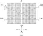
- FIGs. 1 and 2 there are two second connecting pieces 3, and the two second connecting pieces 3 are evenly spaced in the north-south direction, and the length direction of the two second connecting pieces 3 is parallel to the east-west direction.
- One end of the second connecting piece 3 on the north side is connected with one end of one of the first connecting pieces 2, the other end of the second connecting piece 3 on the north side is connected with one end of another first connecting piece 2.
- One end of the second connecting piece 3 on the south side is connected with one end of one of the first connecting pieces 2, and the other end of the second connecting piece 3 on the south side is connected with the other end of another first connecting piece 2.
- Photovoltaic panels 7 are mounted on two mutually parallel second connecting pieces 3.
- the rotating flexible photovoltaic bracket 100 by arranging at least two mutually parallel second connecting pieces 3 for installing photovoltaic panels 7, the photovoltaic panels 7 being installed on the first connecting piece 2 to affect the expansion and contraction of the first connecting piece 2 is prevented, thus the operation reliability of the rotating flexible photovoltaic bracket 100 according to the embodiment of the disclosure is improved.
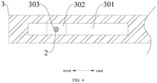
- the second connecting piece 3 is a connecting rod, and both ends of the second connecting piece 3 are respectively provided with sliding rails 301 extending along its length.
- the sliding rail 301 is provided with a slider 302 which is matched with the sliding rail 301 and the slider 302 can slide along the extending direction of the slide rail 301.
- the slider 302 is provided with a perforation 303, and the second connecting piece 3 is connected with the first connecting piece through the perforation 303.
- the western end of the second connecting piece 3 is provided with a first sliding rail, the first sliding rail extends in the east-west direction.
- the first sliding rail is provided with a first slider, the first slider can move with the first sliding rail in the east-west direction.
- the first slider is provided with a first perforation arranged in the north-south direction, and the first connecting piece 2 passes through the first perforation.
- the eastern end of the second connecting piece 3 is provided with a second sliding rail, the second sliding rail extends in the east-west direction.
- a second slider is provided on the second sliding rail, the second slider can slide with the second sliding rail movably in the east-west direction, and the second slider is provided with a second perforation arranged in the north-south direction.
- the first connecting piece 2 connected between the first column 101 and the fourth column 104 passes through the first perforation on the first slider located at the western end of the second connecting piece 3 on the north side
- the first connecting piece 2 connected between the second column 102 and the third column 103 passes through the second perforation on the second slider located at the eastern end of the second connecting piece 3 on the north side, thereby the installation of the second connecting piece 3 on the north side is completed.
- the first connecting piece 2 connected between the second column 102 and the third column 103 passes through the first perforation on the first slider located at the western end of the second connecting piece 3 on the south side, and the first connecting piece 2 connected between the first column 101 and the fourth column 104 passes through the second perforation on the second slider located at the eastern end of the second connecting piece 3 on the south side, thus the installation of the second connecting piece 3 on the south side is completed.
- the rotating flexible photovoltaic bracket 100 further includes driving parts 501, each of the driving parts 501 is connected with the column 1 and each of the driving parts is used for driving corresponding the lifting rod to rotate.
- the driving part 501 is a driving motor
- the driving motor is installed on the column 1 and the driving motor is connected with the lifting rod 402 to drive the lifting rod 402 to rotate.
- the driving part 501 is arranged to drive the lifting rod 402 to rotate, thereby facilitating the rotation of the lifting rod 402, and further facilitating the adjustment of the rotating flexible photovoltaic bracket 100 of the embodiment of the disclosure.
- the rotating flexible photovoltaic bracket 100 of the embodiment of the disclosure further includes a PLC (programmable logic controller) control system, PLC control system is electrically connected with the driving part 501, and PLC control system controls the rotation of the lifting rod 402 by controlling the driving part 501.
- PLC programmable logic controller
- the rotating flexible photovoltaic bracket 100 further includes active parts 502 and passive parts 503, one of the active parts 502 is arranged on each of the columns 1, each of the driving parts 501 is connected with corresponding one of the active parts 502, each of the passive parts 503 is connected with the lifting rod 402, and the active parts 502 are matched with the passive parts 503 so that each of the driving parts 501 drives the lifting rod 402 to rotate.
- the driving part 501 is beneficial to drive the lifting rod 402 to rotate, thus further facilitating the adjustment of the rotating flexible photovoltaic bracket 100 of the embodiment of the disclosure.
- the active parts 502 is a first gear 601, and each of the passive parts 503 is a second gear 602, the first gear 601 is meshed with the second gear 602, and a length of the second gear 602 in an extension direction thereof is greater than a length of the first gear 601 in an extension direction thereof.
- the first gear 601 is sleeved on the output shaft of the driving motor, which drives the first gear 601 to rotate forward when the driving motor rotates forward, and the first gear 601 drives the second gear 602 to rotate forward, the second gear 602 drives the lifting rod 402 to rotate forward, and when the lifting rod 402 rotates forward, it moves upward under the action of screw transmission. That is to say, while the second gear 602 rotates, it moves upward under the drive of the lifting rod 402. Because the length of the second gear 602 in the up-and-down direction is greater than the length of the second gear 601 in the up-and-down direction, so that the first gear 601 and the second gear 602 are always in meshing state.
- the rotating flexible photovoltaic bracket 100 of the embodiment of the disclosure by arranging the active part 502 and the passive part 503 in the form of gear pair transmission, it is beneficial to improving the transmission stability between the active part 502 and the passive part 503 and improving the working reliability of the rotating flexible photovoltaic bracket 100 of the embodiment of the disclosure .
- the rotating flexible photovoltaic bracket 100 further includes a reducer 504, and the driving part 501 and the first gear 601 are connected through the reducer 504.
- the rotating speed of the lifting rod 402 can be better controlled, which is beneficial to controlling the rotating speed of the lifting rod 402 and further facilitating the adjustment of the rotating flexible photovoltaic bracket 100 in the embodiment of the disclosure.
- each of the columns 1 further includes an installation section 106, the threaded section 105 is connected with the installation section 106 in sequence from top to bottom, and the installation section 106 is used for being installed on a foundation.
- the peripheral surface of the installation section 106 is smooth surface, and the installation section 106 is installed on a foundation, for example, the installation section 106 is installed on a reinforced concrete foundation.
- the column 1 is provided with the installation section 106, so that the column 1 can be installed on the foundation, thereby facilitating the installation of the rotating flexible photovoltaic bracket 100.
- first and second are only used for descriptive purposes, and cannot be understood as indicating or implying relative importance or implicitly indicating the number of indicated technical features. Therefore, the features defined as “first” and “second” can explicitly or implicitly include at least one of these features. In the description of this disclosure, “multiple” means at least two, such as two, three, etc., unless otherwise specifically defined.
- the terms “installation”, “connect”, “connection” and “fix” should be broadly understood, for example, it can be fixed connection, can also be detachable connection or integrated; it can be mechanically connected, can also be electrically connected or communicated with each other; it can be directly connected, can also be indirectly connected through an intermediary, and it can be the internal connection of two elements or the interaction relation between two elements, unless otherwise specified.
- installation can be fixed connection, can also be detachable connection or integrated; it can be mechanically connected, can also be electrically connected or communicated with each other; it can be directly connected, can also be indirectly connected through an intermediary, and it can be the internal connection of two elements or the interaction relation between two elements, unless otherwise specified.
- the first feature "above” or “below” the second feature may be that the first and second features are in direct contact, or the first and second features are in indirect contact through an intermediary.
- the first feature is "on”, “above” and “over” the second feature, which can mean that the first feature is directly above or obliquely above the second feature, or just means that the horizontal height of the first feature is higher than that of the second feature.
- the first feature is "under”, “below” and “lower” the second feature can mean that the first feature is directly or obliquely below the second feature, or just means that the horizontal height of the first feature is smaller than that of the second feature.
- the terms “one embodiment”, “some embodiments”, “example”, “specific example” or “some examples” etc. mean that a specific feature, structure, material or characteristic described in connection with this embodiment or example is included in at least one embodiment or example of this disclosure.
- the schematic expressions of the above terms are not necessarily aimed at the same embodiment or example.
- the specific features, structures, materials or characteristics described may be combined in any one or more embodiments or examples in a suitable manner.
- those skilled in the art can integrate and combine different embodiments or examples and features of different embodiments or examples described in this description without contradicting each other.
Landscapes
- Engineering & Computer Science (AREA)
- Life Sciences & Earth Sciences (AREA)
- Sustainable Development (AREA)
- Physics & Mathematics (AREA)
- Sustainable Energy (AREA)
- Thermal Sciences (AREA)
- Chemical & Material Sciences (AREA)
- Combustion & Propulsion (AREA)
- Mechanical Engineering (AREA)
- General Engineering & Computer Science (AREA)
- Photovoltaic Devices (AREA)
Abstract
Description
- The disclosure relates to the technical field of photovoltaic, in particular to a rotating flexible photovoltaic bracket.
- The flexible photovoltaic support changes the purlin in the traditional rigid support technology into steel strand, that is, photovoltaic assembly is installed on rows of steel strands. The pre-tension of steel strand is provided by the first line method, and the two ends of the steel strands are connected by rigid supports, which can realize a large spacing of 10-30m. Sliders are arranged at the two ends of the steel strand, and the angle of the photovoltaic assembly is changed by sliding the sliders up and down, so that the solar tracking of the photovoltaic assembly is realized. With the lifting or lowering of the two sliders at the end of the steel strand, the position between the two sliders changes, which leads to the change of the required length of the steel strand between the two sliders. Because it is difficult to adjust the length of the steel strand between the two sliders, it is inconvenient to adjust the angle of the photovoltaic panel.
- The disclosure aims at solving at least one of the technical problems in the above related background art to some extent.
- Therefore, an embodiment of the disclosure proposes a rotating flexible photovoltaic bracket to facilitate the angle adjustment of photovoltaic panels.
- The rotating flexible photovoltaic bracket of the embodiment of the disclosure includes columns, first connecting pieces and lifting assemblies.
- Each of the columns includes a threaded section, and the threaded section is provided with an internal thread; a plurality of the columns are provided, where the plurality of columns include a first group of columns and a second group of columns, where the first group of columns includes a first column and a second column arranged at intervals along a first direction, and the second group of columns includes a third column and a fourth column arranged at intervals along the first direction; the first group of columns and the second group of columns are arranged along a second direction, the first direction is orthogonal to an up-and-down direction, the second direction is orthogonal to the up-and-down direction, and an angle is formed between the first direction and the second direction.
- The first connecting pieces are provided at least two and are used for installing photovoltaic panels; at least one of the first connecting pieces is connected between the first column and the fourth column; at least one of the first connecting pieces is connected between the second column and the third column, and the first connecting pieces between the first column and the fourth column and the first connecting pieces between the second column and the third column are crossed.
- A plurality of lifting assemblies are provided, the plurality of lifting assemblies correspond to the plurality of columns one by one, and each of the lifting assemblies is connected with a corresponding one of the columns and a position of each of the lifting assemblies relative to the corresponding one of the columns is adjustable in the up-and-down direction.
- Each of the lifting assemblies includes a lifting rod, a lower end of the lifting rod extends into a corresponding one of the columns, and the lifting rod is provided with an external thread being matched with the internal thread, so that the lifting rod is capable of moving in the up-and-down direction along corresponding one of the columns under an action of thread transmission, the lifting rod is provided with a spiral groove, the spiral groove is circumferentially arranged around the lifting rod, a rotation direction of the spiral groove is opposite to a rotation direction of the external thread, each of the first connecting pieces is connected with corresponding one of the columns through the lifting rod, and at least a part of each of the first connecting pieces is wound in the spiral groove.
- When the lifting rod moves in the up-and-down direction, the spiral groove is used for driving corresponding one of the first connecting pieces to expand and contract, so as to adjust a length of each of the first connecting pieces between two spiral grooves.
- The rotating flexible photovoltaic bracket in the embodiment of the disclosure has the advantages of convenient adjustment of the photovoltaic panel angle and the like.
- In some embodiments, each of the lifting assemblies further includes a first rotating shaft, and the first rotating shaft is used for supporting corresponding one of the first connecting pieces extending from an upper end of the spiral groove, so that the corresponding one of the first connecting pieces rotates spirally in the spiral groove.
- In some embodiments, each of the lifting assemblies further includes a second rotating shaft, the second rotating shaft and the first rotating shaft are arranged at intervals in the up-and-down direction, and the second rotating shaft is used for supporting corresponding one of the first connecting pieces extending from a lower end of the spiral groove, so that each of the first connecting pieces rotates spirally in the spiral groove.
- In some embodiments, each of the lifting assemblies further includes a support frame, the support frame is rotatably connected with the lifting rod around an axis of the lifting rod, and each of the first rotating shaft and the second rotating shaft is connected with the support frame.
- In some embodiments, the rotating flexible photovoltaic bracket further includes at least two parallel second connecting pieces, where one end of each of the second connecting pieces is connected with at least one of the first connecting pieces, and an other end of each of the second connecting pieces is connected with at least one of the first connecting pieces, and the second connecting pieces are used for installing the photovoltaic panels.
- In some embodiments, each of the second connecting pieces is a connecting rod, and both ends of each of the second connecting pieces are respectively provided with sliding rails extending along a length thereof; each of the sliding rails is provided with a slider matched with corresponding one of the sliding rails, the slider is capable of sliding along an extending direction of corresponding one of the sliding rails; the slider is provided with a perforation, and each of the second connecting pieces is connected with corresponding one of the first connecting pieces through the perforation.
- In some embodiments, the rotating flexible photovoltaic bracket further includes driving parts, each of the driving parts is connected with corresponding one of the columns and each of the driving parts is used for driving corresponding the lifting rod to rotate.
- In some embodiments, the rotating flexible photovoltaic bracket further includes active parts and passive parts, one of the active parts is arranged on each of the columns, each of the driving parts is connected with corresponding one of the active parts, each of the passive parts is connected with the lifting rod, and the active parts are matched with the passive parts so that each of the driving parts drives the lifting rod to rotate.
- In some embodiments, each of the active parts is a first gear, and each of the passive parts is a second gear, the first gear is meshed with the second gear, and a length of the second gear in an extension direction thereof is greater than a length of the first gear in an extension direction thereof.
- In some embodiments, the first connecting pieces are steel strands.
- In some embodiments, each of the columns further includes an installation section, the threaded section is connected with the installation section in sequence from top to bottom, and the installation section is used for being installed on a foundation.
-
-
FIG. 1 is a usage state diagram of a rotating flexible photovoltaic bracket according to an embodiment of the disclosure; -
FIG. 2 is a usage state diagram of the first connecting pieces and the second connecting pieces according to an embodiment of the disclosure; -
FIG 3 is a schematic structural diagram of a lifting assembly according to another embodiment of the disclosure; -
FIG. 4 is a schematic structural diagram of the connection between the first connecting piece and the second connecting piece according to another embodiment of the disclosure; -
FIG. 5 is a schematic diagram of the use state of the second column and the third column according to another embodiment of the disclosure; -
FIG. 6 is a schematic diagram of a use state of the first connecting piece and the second connecting piece according to another embodiment of the disclosure; and -
FIG. 7 is a schematic diagram of another use state of the first connecting piece and the second connecting piece according to another embodiment of the disclosure. - List of reference character: 100 rotating flexible photovoltaic bracket; 1 column; 101 first column; 102 second column; 103 third column; 104 fourth column; 105 threaded section; 106 installation section; 2 first connecting piece; 3 second connecting piece; 301 sliding rail; 302 slider; 303 perforation; 4 lifting assembly; 4011 first rotating shaft; 4012 second rotating shaft; 4013 support frame; 402 lifting rod; 4021 spiral groove; 501 driving part; 502 active part; 503 passive part; 504 reducer; 601 first gear; 602 second gear; and 7 photovoltaic panel.
- In the following, embodiments of the disclosure will be described in detail, examples of which are illustrated in the accompanying drawings. The embodiments described below by referring to the drawings are exemplary and are intended to explain the disclosure, but not to be construed as limiting the disclosure.
- Hereinafter, the technical scheme of the disclosure will be described in detail with reference to the attached drawings.
- As shown in
FIGs. 1 to 7 , the rotating flexiblephotovoltaic bracket 100 of the embodiment of the disclosure includes columns 1, first connectingpieces 2 and lifting assemblies 4. Each of the columns 1 includes a threadedsection 105, and the threadedsection 105 is provided with an internal thread. Multiple columns are provided, where the multiple columns include a first group of columns and a second group of columns. The first group of columns includes afirst column 101 and asecond column 102 arranged at intervals along a first direction, and the second group of columns includes athird column 103 and afourth column 104 arranged at intervals along the first direction. The first group of columns and the second group of columns are arranged along a second direction. The first direction is orthogonal to an up-and-down direction, the second direction is orthogonal to the up-and-down direction, and an angle is formed between the first direction and the second direction; - At least one of the first connecting
pieces 2 is connected between thefirst column 101 and thefourth column 104; at least one of the first connectingpieces 2 is connected between thesecond column 102 and thethird column 103, and the first connectingpieces 2 between thefirst column 101 and thefourth column 104 and the first connectingpieces 2 between thesecond column 102 and thethird column 103 are crossed. Multiple lifting assemblies 4 are provided, the multiple lifting assemblies 4 correspond to multiple columns 1 one by one, and each of the lifting assemblies 4 is connected with a corresponding one of the columns 1 and a position of each of the lifting assemblies relative to the corresponding one of the columns 1 is adjustable in the up-and-down direction. - Each of the lifting assemblies includes a lifting rod 402, a lower end of the lifting rod 402 extends into a corresponding one of the columns 1, and the lifting rod 402 is provided with an external thread being matched with the internal thread, so that the lifting rod 402 is capable of moving in the up-and-down direction along corresponding one of the columns 1 under an action of thread transmission. The lifting rod 402 is provided with a
spiral groove 4021, thespiral groove 4021 is circumferentially arranged around the lifting rod 402, a rotation direction of thespiral groove 4021 is opposite to a rotation direction of the external thread. Each of the first connectingpieces 2 is connected with corresponding one of the columns 1 through the lifting rod 402, and at least a part of each of the first connectingpieces 2 is wound in thespiral groove 4021; - When the lifting rod 402 moves in the up-and-down direction, the
spiral groove 4021 is used for driving corresponding one of the first connectingpieces 2 to expand and contract, so as to adjust a length of each of the first connectingpieces 2 between twospiral grooves 4021. - In order to make the technical scheme of the disclosure easier to understand, the technical scheme of the disclosure will be further described below by taking the first direction consistent with the east-west direction and the second direction consistent with the north-south direction as examples, where the east-west direction and the north-south direction are shown in
FIG. 1 . - For example, as shown in
FIG. 1 , thefirst column 101 is located on the west side of thesecond column 102, thethird column 103 is located on the west side of thefourth column 104, the first group of columns is located on the north side of the second group of columns. Thefirst column 101 and thethird column 103 correspond in the north-south direction, and thesecond column 102 and thefourth column 104 correspond in the north-south direction. The highest position and the lowest position of the movement of the lifting assembly 4 on each column 1 are the same. It can be understood that the photovoltaic panel 7 of the rotating flexiblephotovoltaic bracket 100 in the embodiment of the disclosure is in an initial state (for example, at 7:00 a.m.) presents a posture of high in the west and low in the east, that is, thesecond column 102 and thefourth column 104 are at the lowest point, and thefirst column 101 and thethird column 103 are at the highest point. Of course, the rotating flexiblephotovoltaic bracket 100 of the embodiment of the disclosure presents the posture of the photovoltaic panel 7 in the end state (for example, at 19:00 pm) presents a posture of high in the east and low in the west, that is, thesecond column 102 and thefourth column 104 are located at the highest point, and thefirst column 101 and thethird column 103 are located at the lowest point. - The initial length of the first connecting
piece 2 is the linear distance between the lifting assembly 4 on thefirst column 101 at the highest point and the lifting assembly 4 on thefourth column 104 at the lowest point, plus the linear distance between the highest point and the lowest point of the lifting assembly 4 on thefirst column 101, plus the length of the two ends of the first connecting piece 4 connected with thefirst column 101 and thefourth column 104 through correspondingspiral groove 4021 respectively. - As shown in
FIG. 3 , when the lifting rod 402 rotates forward, the lifting rod 402 moves upward under the action of spiral transmission, and the first connectingpiece 2 extends in from the upper end of thespiral groove 4021 and extends out from the lower end of thespiral groove 4021 under the action of thespiral groove 4021. When the lifting rod 402 rotates reversely, the lifting rod 402 moves downward under the action of spiral transmission, and the first connectingpiece 2 extends in from the lower end of thespiral groove 4021 and extends out from the upper end of thespiral groove 4021 under the action of thespiral groove 4021. - When the rotating flexible
photovoltaic bracket 100 according to the embodiment of the disclosure is used, for example, when the sun is in the south at 12:00 noon, it is necessary to change the photovoltaic panel 7 from an inclined posture of being high in the west and low in the east to an inclined posture of being high in the north and low in the south (as shown inFIG 1 ). The lifting assembly 4 on thesecond column 102 is controlled to ascend, and meanwhile the lifting assembly 4 on thethird column 103 is controlled to descend at the same speed as the lifting assembly 4 on thesecond column 102. So that the lifting assembly 4 on thesecond column 102 is raised to the same height as the lifting assembly 4 on thefirst column 101, and the lifting assembly 4 on thethird column 103 is lowered to the same height as the lifting assembly 4 on thefourth column 104, so that the photovoltaic panels 7 present a posture of high in the north and low in the south. During ascending of the lifting assembly 4 on thesecond column 102, thespiral groove 4021 on thesecond column 102 drives the length of the first connectingpiece 2 between the top end of thesecond column 102 and thespiral groove 4021 on thesecond column 102 to extend. During descending of the lifting assembly 4 on thethird column 103, thespiral groove 4021 on thethird column 103 drives the length of the first connectingpiece 2 between the top end of thethird column 103 and thespiral groove 4021 on thethird column 103 to shorten, so as to compensate the distance change caused by the relative position change between thespiral groove 4021 on thesecond column 102 and thespiral groove 4021 on thethird column 103. As shown inFIG. 5 , the first connectingpiece 2 connected between thesecond column 102 and thethird column 103 is changed from the inclined state shown by dotted lines to the inclined state shown by solid lines, so that the length difference of the first connectingpiece 2 generated by the movement of the lifting assembly 4 in up-and down direction forms an equal triangle. The upper and lower lengths of the first connectingpiece 2 in thesecond column 102 and thethird column 103 complement each other, so that the photovoltaic panels 7 present a posture of high in the north and low in the south. - For example, when the sun is in the west at 16:00 p.m., it is necessary to change the photovoltaic panels 7 from an inclined posture of high in the north and low in the south (as shown in
FIG. 1 ) to an inclined posture of high in the east and low in the west. The lifting assembly 4 on thefourth column 104 is controlled to ascend, and at meanwhile, the lifting assembly 4 on thefirst column 101 is controlled to descend at the same speed as the lifting assembly 4 on thefourth column 104. So that the lifting assembly 4 on thefourth column 104 is raised to the same height as the lifting assembly 4 on thesecond column 102, and the lifting assembly 4 on thefirst column 101 is lowered to the same height as the lifting assembly 4 on thethird column 103, so that the photovoltaic panels 7 present a posture of high in the north and low in the south. During ascending of the lifting assembly 4 on thefourth column 104, thespiral groove 4021 on thefourth column 104 drives the length of the first connectingpiece 2 between the top end of thefourth column 104 and thespiral groove 4021 on thefourth column 104 to be shortened. During descending of the lifting assembly 4 on thefirst column 101, thespiral groove 4021 on thefirst column 101 drives the length of the first connectingpiece 2 between the top end of thefirst column 101 and thespiral groove 4021 on thefirst column 101 to extend, so as to compensate for the distance change caused by the relative position change between thespiral groove 4021 on thefourth column 104 and thespiral groove 4021 on thefirst column 101. - Therefore, in the rotating flexible
photovoltaic bracket 100 of the embodiment of the disclosure, thespiral groove 4021 is arranged on the lifting rod 402, and when the position of thespiral groove 4021 connecting the two ends of the first connectingpiece 2 changes relatively, thespiral groove 4021 drives the first connectingpiece 2 to expand and contract, so as to adjust the distance change of thespiral groove 4021 at the two ends of the first connectingpiece 2 due to the relative position change, thereby facilitating the adjustment of the photovoltaic panels 7 of the rotating flexiblephotovoltaic bracket 100 of the embodiment of the disclosure. - Therefore, the rotating flexible
photovoltaic bracket 100 of the embodiment of the disclosure has the advantages of convenient angle adjustment of the photovoltaic panels 7. Optionally, the connecting piece is a steel strand. - In some embodiments, the lifting assembly 4 further includes a first
rotating shaft 4011, and the firstrotating shaft 4011 is used for supporting the first connectingpiece 2 extending from an upper end of thespiral groove 4021, so that the first connectingpiece 2 rotates spirally in thespiral groove 4021. - For example, as shown in
FIG. 3 , the axis of the firstrotating shaft 4011 is arranged in the north-south direction, the firstrotating shaft 4011 is arranged close to the upper end of thespiral groove 4021, and the first connectingpiece 2 is wound around the firstrotating shaft 4011 so that the first connectingpiece 2 can extend in or out from the upper end of thespiral groove 4021. - Therefore, by arranging the first
rotating shaft 4011, it is beneficial for the first connectingpiece 2 to extend in or out from the upper end of thespiral groove 4021, and it is beneficial to improve the operation reliability of the rotating flexiblephotovoltaic bracket 100 of the embodiment of the disclosure. - In some embodiments, the lifting assembly 4 further includes a second
rotating shaft 4012, the secondrotating shaft 4012 and the firstrotating shaft 4011 are arranged at intervals in the up-and-down direction, and the secondrotating shaft 4012 is used for supporting the first connectingpiece 2 extending from a lower end of thespiral groove 4021, so that the first connectingpiece 2 rotates spirally in thespiral groove 4021. - For example, as shown in
FIG. 3 , the axis of the secondrotating shaft 4012 is arranged in the north-south direction, and the secondrotating shaft 4012 is arranged close to the lower end of thespiral groove 4021, and the first connectingpiece 2 is wound around the secondrotating shaft 4012 so that the first connectingpiece 2 can extend in or out from the lower end of thespiral groove 4021. - Therefore, by arranging the second
rotating shaft 4012, it is beneficial for the first connectingpiece 2 to extend in or out from the lower end of thespiral groove 4021, and it is beneficial to improve the operation reliability of the rotating flexiblephotovoltaic bracket 100 of the embodiment of the disclosure. - In some embodiments, the lifting assembly 4 further includes a support frame 4013, the support frame 4013 is rotatably connected with the lifting rod 402 around an axis of the lifting rod 402, and each of the first
rotating shaft 4011 and the secondrotating shaft 4012 is connected with the support frame 4013. - For example, as shown in
FIG. 3 , the support frame 4013 has a first part and a second part which are connected. The first part is cylindrical and sleeved on the lifting rod 402, and can rotate around the axis of the lifting rod 402. The firstrotating shaft 4011 and the secondrotating shaft 4012 are rotatably arranged on the second part, so that the firstrotating shaft 4011 and the secondrotating shaft 4012 can support the first connectingpiece 2. - Therefore, in the rotating flexible
photovoltaic bracket 100 of the embodiment of the disclosure, by arranging that the support frame is rotatably connected with the lifting rod 402, so as to facilitate the installation of the firstrotating shaft 4011 and the secondrotating shaft 4012, thus making the rotating flexiblephotovoltaic bracket 100 of the embodiment of the disclosure simple in structure. - In some embodiments, the rotating flexible photovoltaic bracket further includes at least two mutually parallel second connecting
pieces 3, where one end of each of the second connectingpieces 3 is connected with at least one of the first connectingpieces 2, and an other end of each of the second connectingpieces 3 is connected with at least one of the first connectingpieces 2, and the second connectingpieces 3 are used for installing the photovoltaic panels 7. - For example, as shown in
FIGs. 1 and2 , there are two second connectingpieces 3, and the two second connectingpieces 3 are evenly spaced in the north-south direction, and the length direction of the two second connectingpieces 3 is parallel to the east-west direction. One end of the second connectingpiece 3 on the north side is connected with one end of one of the first connectingpieces 2, the other end of the second connectingpiece 3 on the north side is connected with one end of another first connectingpiece 2. One end of the second connectingpiece 3 on the south side is connected with one end of one of the first connectingpieces 2, and the other end of the second connectingpiece 3 on the south side is connected with the other end of another first connectingpiece 2. Photovoltaic panels 7 are mounted on two mutually parallel second connectingpieces 3. - Therefore, in the the rotating flexible
photovoltaic bracket 100 according to the embodiment of the disclosure, by arranging at least two mutually parallel second connectingpieces 3 for installing photovoltaic panels 7, the photovoltaic panels 7 being installed on the first connectingpiece 2 to affect the expansion and contraction of the first connectingpiece 2 is prevented, thus the operation reliability of the rotating flexiblephotovoltaic bracket 100 according to the embodiment of the disclosure is improved. - Optionally, as shown in
FIG. 5 , the second connectingpiece 3 is a connecting rod, and both ends of the second connectingpiece 3 are respectively provided with slidingrails 301 extending along its length. The slidingrail 301 is provided with aslider 302 which is matched with the slidingrail 301 and theslider 302 can slide along the extending direction of theslide rail 301. Theslider 302 is provided with aperforation 303, and the second connectingpiece 3 is connected with the first connecting piece through theperforation 303. - The western end of the second connecting
piece 3 is provided with a first sliding rail, the first sliding rail extends in the east-west direction. The first sliding rail is provided with a first slider, the first slider can move with the first sliding rail in the east-west direction. The first slider is provided with a first perforation arranged in the north-south direction, and the first connectingpiece 2 passes through the first perforation. - The eastern end of the second connecting
piece 3 is provided with a second sliding rail, the second sliding rail extends in the east-west direction. A second slider is provided on the second sliding rail, the second slider can slide with the second sliding rail movably in the east-west direction, and the second slider is provided with a second perforation arranged in the north-south direction. - Specifically, when the second connecting
piece 3 is connected with the first connectingpiece 2, for example, as shown inFIG. 1 , the first connectingpiece 2 connected between thefirst column 101 and thefourth column 104 passes through the first perforation on the first slider located at the western end of the second connectingpiece 3 on the north side, and the first connectingpiece 2 connected between thesecond column 102 and thethird column 103 passes through the second perforation on the second slider located at the eastern end of the second connectingpiece 3 on the north side, thereby the installation of the second connectingpiece 3 on the north side is completed. The first connectingpiece 2 connected between thesecond column 102 and thethird column 103 passes through the first perforation on the first slider located at the western end of the second connectingpiece 3 on the south side, and the first connectingpiece 2 connected between thefirst column 101 and thefourth column 104 passes through the second perforation on the second slider located at the eastern end of the second connectingpiece 3 on the south side, thus the installation of the second connectingpiece 3 on the south side is completed. - When in use, as shown in
FIGs. 6 and7 , when the intersection angle between the two first connectingpieces 2 changes, the first slider and the second slider at the east and west ends of the second connectingpiece 3 slide in the east-west direction to compensate for the displacement change of the two first connectingpieces 2 caused by the intersection angle change, thus facilitating the adjustment of the first connectingpieces 2 and further facilitating the adjustment of the rotating flexiblephotovoltaic bracket 100 of the embodiment of the disclosure. - In some embodiments, the rotating flexible
photovoltaic bracket 100 further includes drivingparts 501, each of the drivingparts 501 is connected with the column 1 and each of the driving parts is used for driving corresponding the lifting rod to rotate. - For example, the driving
part 501 is a driving motor, the driving motor is installed on the column 1 and the driving motor is connected with the lifting rod 402 to drive the lifting rod 402 to rotate. - Therefore, the driving
part 501 is arranged to drive the lifting rod 402 to rotate, thereby facilitating the rotation of the lifting rod 402, and further facilitating the adjustment of the rotating flexiblephotovoltaic bracket 100 of the embodiment of the disclosure. - Optionally, the rotating flexible
photovoltaic bracket 100 of the embodiment of the disclosure further includes a PLC (programmable logic controller) control system, PLC control system is electrically connected with the drivingpart 501, and PLC control system controls the rotation of the lifting rod 402 by controlling the drivingpart 501. - By setting the PLC control system, it is convenient to control the lifting speed of the lifting assembly 4, so as to facilitate the adjustment of the lifting speed of the lifting assembly 4 connected at both ends of the first connecting
piece 2, to facilitate the adjustment of the angle of the photovoltaic panels 7, and to improve the operation reliability of the rotating flexiblephotovoltaic bracket 100 of the embodiment of the disclosure. - In some embodiments, the rotating flexible
photovoltaic bracket 100 further includesactive parts 502 andpassive parts 503, one of theactive parts 502 is arranged on each of the columns 1, each of the drivingparts 501 is connected with corresponding one of theactive parts 502, each of thepassive parts 503 is connected with the lifting rod 402, and theactive parts 502 are matched with thepassive parts 503 so that each of the drivingparts 501 drives the lifting rod 402 to rotate. - By arranging the
active part 502 and thepassive part 503, the drivingpart 501 is beneficial to drive the lifting rod 402 to rotate, thus further facilitating the adjustment of the rotating flexiblephotovoltaic bracket 100 of the embodiment of the disclosure. - Optionally, the
active parts 502 is afirst gear 601, and each of thepassive parts 503 is asecond gear 602, thefirst gear 601 is meshed with thesecond gear 602, and a length of thesecond gear 602 in an extension direction thereof is greater than a length of thefirst gear 601 in an extension direction thereof. - For example, as shown in
FIG. 3 , thefirst gear 601 is sleeved on the output shaft of the driving motor, which drives thefirst gear 601 to rotate forward when the driving motor rotates forward, and thefirst gear 601 drives thesecond gear 602 to rotate forward, thesecond gear 602 drives the lifting rod 402 to rotate forward, and when the lifting rod 402 rotates forward, it moves upward under the action of screw transmission.. That is to say, while thesecond gear 602 rotates, it moves upward under the drive of the lifting rod 402. Because the length of thesecond gear 602 in the up-and-down direction is greater than the length of thesecond gear 601 in the up-and-down direction, so that thefirst gear 601 and thesecond gear 602 are always in meshing state. - Therefore, in the rotating flexible
photovoltaic bracket 100 of the embodiment of the disclosure, by arranging theactive part 502 and thepassive part 503 in the form of gear pair transmission, it is beneficial to improving the transmission stability between theactive part 502 and thepassive part 503 and improving the working reliability of the rotating flexiblephotovoltaic bracket 100 of the embodiment of the disclosure . - Optionally, the rotating flexible
photovoltaic bracket 100 further includes areducer 504, and the drivingpart 501 and thefirst gear 601 are connected through thereducer 504. - By arranging the
reducer 504 between the driving motor and thefirst gear 601, the rotating speed of the lifting rod 402 can be better controlled, which is beneficial to controlling the rotating speed of the lifting rod 402 and further facilitating the adjustment of the rotating flexiblephotovoltaic bracket 100 in the embodiment of the disclosure. - In some embodiments, each of the columns 1 further includes an
installation section 106, the threadedsection 105 is connected with theinstallation section 106 in sequence from top to bottom, and theinstallation section 106 is used for being installed on a foundation. - For example, as shown in
FIG. 3 , the peripheral surface of theinstallation section 106 is smooth surface, and theinstallation section 106 is installed on a foundation, for example, theinstallation section 106 is installed on a reinforced concrete foundation. - Therefore, in the rotating flexible
photovoltaic bracket 100 in the embodiment of the disclosure, the column 1 is provided with theinstallation section 106, so that the column 1 can be installed on the foundation, thereby facilitating the installation of the rotating flexiblephotovoltaic bracket 100. - In the description of the disclosure, it should be understood that the azimuth or positional relationship indicated by the terms "center", "longitudinal", "lateral", "length", "width", "thickness", "up", "down", "front", "back", "left", "right", "vertical", "horizontal", "top", "bottom", "inside", "outside", "clockwise", "counterclockwise", "axial", "radial" and "circumferential" is based on the azimuth or positional relationship shown in the attached drawings, only for the convenience of describing this disclosure and simplifying the description, and does not indicate or imply that the referred device or element must have a specific orientation, be constructed and operated in a specific orientation, so it cannot be understood as a limitation of this disclosure.
- In addition, the terms "first" and "second" are only used for descriptive purposes, and cannot be understood as indicating or implying relative importance or implicitly indicating the number of indicated technical features. Therefore, the features defined as "first" and "second" can explicitly or implicitly include at least one of these features. In the description of this disclosure, "multiple" means at least two, such as two, three, etc., unless otherwise specifically defined.
- In this disclosure, unless otherwise specified and limited, the terms "installation", "connect", "connection" and "fix" should be broadly understood, for example, it can be fixed connection, can also be detachable connection or integrated; it can be mechanically connected, can also be electrically connected or communicated with each other; it can be directly connected, can also be indirectly connected through an intermediary, and it can be the internal connection of two elements or the interaction relation between two elements, unless otherwise specified. For those skilled in the art, the specific meanings of the above terms in this disclosure can be understood according to specific situations.
- In this disclosure, unless otherwise specified and limited, the first feature "above" or "below" the second feature may be that the first and second features are in direct contact, or the first and second features are in indirect contact through an intermediary. Moreover, the first feature is "on", "above" and "over" the second feature, which can mean that the first feature is directly above or obliquely above the second feature, or just means that the horizontal height of the first feature is higher than that of the second feature. The first feature is "under", "below" and "lower" the second feature can mean that the first feature is directly or obliquely below the second feature, or just means that the horizontal height of the first feature is smaller than that of the second feature.
- In this disclosure, the terms "one embodiment", "some embodiments", "example", "specific example" or "some examples" etc. mean that a specific feature, structure, material or characteristic described in connection with this embodiment or example is included in at least one embodiment or example of this disclosure. In this description, the schematic expressions of the above terms are not necessarily aimed at the same embodiment or example. Moreover, the specific features, structures, materials or characteristics described may be combined in any one or more embodiments or examples in a suitable manner. In addition, those skilled in the art can integrate and combine different embodiments or examples and features of different embodiments or examples described in this description without contradicting each other.
- Although the above-mentioned embodiments have been shown and described, it can be understood that the above-mentioned embodiments are exemplary and cannot be understood as limitations of the disclosure, and changes, modifications, substitutions and variations made to the above-mentioned embodiments by those skilled in the art are within the protection scope of the disclosure.
Claims (10)
- A rotating flexible photovoltaic bracket, comprising:columns, wherein each of the columns comprises a threaded section, and the threaded section is provided with an internal thread; a plurality of the columns are provided, wherein the plurality of columns comprise a first group of columns and a second group of columns, wherein the first group of columns comprises a first column and a second column arranged at intervals along a first direction, and the second group of columns comprises a third column and a fourth column arranged at intervals along the first direction; the first group of columns and the second group of columns are arranged along a second direction, the first direction is orthogonal to an up-and-down direction, the second direction is orthogonal to the up-and-down direction, and an angle is formed between the first direction and the second direction;first connecting pieces, wherein the first connecting pieces are provided at least two and are used for installing photovoltaic panels; at least one of the first connecting pieces is connected between the first column and the fourth column; at least one of the first connecting pieces is connected between the second column and the third column, and the first connecting pieces between the first column and the fourth column and the first connecting pieces between the second column and the third column are crossed; andlifting assemblies, wherein a plurality of lifting assemblies are provided, the plurality of lifting assemblies correspond to the plurality of columns one by one, and each of the lifting assemblies is connected with a corresponding one of the columns and a position of each of the lifting assemblies relative to the corresponding one of the columns is adjustable in the up-and-down direction;each of the lifting assemblies comprises a lifting rod, a lower end of the lifting rod extends into a corresponding one of the columns, and the lifting rod is provided with an external thread being matched with the internal thread, so that the lifting rod is capable of moving in the up-and-down direction along corresponding one of the columns under an action of thread transmission, the lifting rod is provided with a spiral groove, the spiral groove is circumferentially arranged around the lifting rod, a rotation direction of the spiral groove is opposite to a rotation direction of the external thread, each of the first connecting pieces is connected with corresponding one of the columns through the lifting rod, and at least a part of each of the first connecting pieces is wound in the spiral groove;wherein when the lifting rod moves in the up-and-down direction, the spiral groove is used for driving corresponding one of the first connecting pieces to expand and contract, so as to adjust a length of each of the first connecting pieces between two spiral grooves.
- The rotating flexible photovoltaic bracket according to claim 1, wherein each of the lifting assemblies further comprises a first rotating shaft, and the first rotating shaft is used for supporting corresponding one of the first connecting pieces extending from an upper end of the spiral groove, so that the corresponding one of the first connecting pieces rotates spirally in the spiral groove.
- The rotating flexible photovoltaic bracket according to claim 2, wherein each of the lifting assemblies further comprises a second rotating shaft, the second rotating shaft and the first rotating shaft are arranged at intervals in the up-and-down direction, and the second rotating shaft is used for supporting corresponding one of the first connecting pieces extending from a lower end of the spiral groove, so that each of the first connecting pieces rotates spirally in the spiral groove.
- The rotating flexible photovoltaic bracket according to claim 3, wherein each of the lifting assemblies further comprises a support frame, the support frame is rotatably connected with the lifting rod around an axis of the lifting rod, and each of the first rotating shaft and the second rotating shaft is connected with the support frame.
- The rotating flexible photovoltaic bracket according to any one of claims 1-4, further comprising at least two mutually parallel second connecting pieces, wherein one end of each of the second connecting pieces is connected with at least one of the first connecting pieces, and an other end of each of the second connecting pieces is connected with at least one of the first connecting pieces, and the second connecting pieces are used for installing the photovoltaic panels.
- The rotating flexible photovoltaic bracket according to claim 5, wherein each of the second connecting pieces is a connecting rod, and both ends of each of the second connecting pieces are respectively provided with sliding rails extending along a length thereof; each of the sliding rails is provided with a slider matched with corresponding one of the sliding rails, the slider is capable of sliding along an extending direction of corresponding one of the sliding rails; the slider is provided with a perforation, and each of the second connecting pieces is connected with corresponding one of the first connecting pieces through the perforation.
- The rotating flexible photovoltaic bracket according to any one of claims 1-4, wherein the rotating flexible photovoltaic bracket further comprises driving parts, each of the driving parts is connected with corresponding one of the columns and each of the driving parts is used for driving corresponding the lifting rod to rotate.
- The rotating flexible photovoltaic bracket according to claim 7, wherein the rotating flexible photovoltaic bracket further comprises active parts and passive parts, one of the active parts is arranged on each of the columns, each of the driving parts is connected with corresponding one of the active parts, each of the passive parts is connected with the lifting rod, and the active parts are matched with the passive parts so that each of the driving parts drives the lifting rod to rotate.
- The rotating flexible photovoltaic bracket according to claim 8, wherein each of the active parts is a first gear, and each of the passive parts is a second gear, the first gear is meshed with the second gear, and a length of the second gear in an extension direction thereof is greater than a length of the first gear in an extension direction thereof.
- The rotating flexible photovoltaic bracket according to claim 9, wherein each of the columns further comprises an installation section, the threaded section is connected with the installation section in sequence from top to bottom, and the installation section is used for being installed on a foundation.
Applications Claiming Priority (2)
| Application Number | Priority Date | Filing Date | Title |
|---|---|---|---|
| CN202210348621.3A CN114710100B (en) | 2022-04-01 | 2022-04-01 | Rotating flexible photovoltaic bracket |
| PCT/CN2022/100600 WO2023184739A1 (en) | 2022-04-01 | 2022-08-04 | Rotary flexible photovoltaic support |
Publications (2)
| Publication Number | Publication Date |
|---|---|
| EP4564663A1 true EP4564663A1 (en) | 2025-06-04 |
| EP4564663A4 EP4564663A4 (en) | 2026-03-04 |
Family
ID=82172942
Family Applications (1)
| Application Number | Title | Priority Date | Filing Date |
|---|---|---|---|
| EP22934562.4A Pending EP4564663A4 (en) | 2022-04-01 | 2022-08-04 | Rotary flexible photovoltaic support |
Country Status (3)
| Country | Link |
|---|---|
| EP (1) | EP4564663A4 (en) |
| CN (1) | CN114710100B (en) |
| WO (1) | WO2023184739A1 (en) |
Families Citing this family (6)
| Publication number | Priority date | Publication date | Assignee | Title |
|---|---|---|---|---|
| CN114710100B (en) * | 2022-04-01 | 2025-01-24 | 华能大理风力发电有限公司洱源分公司 | Rotating flexible photovoltaic bracket |
| CN116743038B (en) * | 2023-05-22 | 2024-02-20 | 神龙拜耳科技衡水股份有限公司 | Flexible photovoltaic bracket suitable for complex terrain |
| CN117344953B (en) * | 2023-11-02 | 2026-05-08 | 中国电建集团江西省电力设计院有限公司 | An adjustable photovoltaic carport module installation platform |
| CN117937344B (en) * | 2024-03-22 | 2024-06-04 | 国清环境发展有限公司 | Photovoltaic board cable fixed mounting structure |
| CN118157557B (en) * | 2024-05-10 | 2024-07-19 | 安徽永汇电力工程有限公司 | Unilateral pressing block assembly for steel strand flexible support and construction method |
| CN120362573B (en) * | 2025-06-26 | 2026-01-06 | 靖江市洪力金属制品有限公司 | A smart adaptive cutting device for metal processing |
Family Cites Families (15)
| Publication number | Priority date | Publication date | Assignee | Title |
|---|---|---|---|---|
| WO2008064382A2 (en) * | 2006-11-30 | 2008-06-05 | Innova Patent Gmbh | System for generating electric power by means of photovoltaic elements |
| US8766091B2 (en) * | 2007-06-29 | 2014-07-01 | Oliver J. Edwards | Solar power harvester |
| CN202645911U (en) * | 2012-05-25 | 2013-01-02 | 集美大学 | Sunflower type power-storage-free solar photovoltaic pump |
| KR101656445B1 (en) * | 2016-04-12 | 2016-09-09 | 신동율 | Solar power system |
| CN207399102U (en) * | 2017-10-19 | 2018-05-22 | 天津威全新能源科技有限公司 | A kind of manual adjustable photovoltaic support |
| CN108494324B (en) * | 2018-03-02 | 2020-05-22 | 陈建凡 | Photovoltaic board convenient to adjust |
| JP7252063B2 (en) * | 2019-06-05 | 2023-04-04 | 勝美 衛藤 | photovoltaic device |
| CN209805735U (en) * | 2019-06-24 | 2019-12-17 | 江苏石光光伏有限公司 | Solar photovoltaic module support with adjustable inclination angle |
| KR102308740B1 (en) * | 2019-07-17 | 2021-10-05 | 루이산업기술(주) | apparatus adjusting angle of solar module |
| CN212875741U (en) * | 2020-08-08 | 2021-04-02 | 金麒麟建设科技股份有限公司 | Multifunctional photovoltaic power station operation real-time monitoring system |
| CN112468068A (en) * | 2020-11-04 | 2021-03-09 | 江苏中信博新能源科技股份有限公司 | Flexible adjustable photovoltaic support |
| CN215010134U (en) * | 2021-04-28 | 2021-12-03 | 天津东景元坤船舶工程有限公司 | Adjustable photovoltaic flexible support |
| CN216122303U (en) * | 2021-09-18 | 2022-03-22 | 上海兴邺材料科技有限公司 | Photovoltaic device and photovoltaic system |
| CN114710100B (en) * | 2022-04-01 | 2025-01-24 | 华能大理风力发电有限公司洱源分公司 | Rotating flexible photovoltaic bracket |
| CN217469842U (en) * | 2022-04-01 | 2022-09-20 | 华能大理风力发电有限公司洱源分公司 | Rotary flexible photovoltaic support |
-
2022
- 2022-04-01 CN CN202210348621.3A patent/CN114710100B/en active Active
- 2022-08-04 EP EP22934562.4A patent/EP4564663A4/en active Pending
- 2022-08-04 WO PCT/CN2022/100600 patent/WO2023184739A1/en not_active Ceased
Also Published As
| Publication number | Publication date |
|---|---|
| CN114710100A (en) | 2022-07-05 |
| WO2023184739A1 (en) | 2023-10-05 |
| CN114710100B (en) | 2025-01-24 |
| EP4564663A4 (en) | 2026-03-04 |
Similar Documents
| Publication | Publication Date | Title |
|---|---|---|
| CN114710100B (en) | Rotating flexible photovoltaic bracket | |
| KR102308740B1 (en) | apparatus adjusting angle of solar module | |
| CN114840033B (en) | A single-axis tracking flexible photovoltaic bracket and photovoltaic power generation system | |
| CA2789510A1 (en) | Automatic sunlight tracking device | |
| CN209545516U (en) | A kind of tracking type solar panels movable support of simple to install | |
| CN115516255A (en) | Solar tracking device | |
| CN106094894A (en) | Solar energy tracking mutual ter axle twin columns robot | |
| CN217362975U (en) | Rotary flexible photovoltaic support | |
| CN217469842U (en) | Rotary flexible photovoltaic support | |
| CN218499083U (en) | Photovoltaic support with adjustable inclination angle | |
| KR101594736B1 (en) | Angle adjustment | |
| CN113228999A (en) | Greenhouse external heat preservation quilt crossing type paving and rolling device | |
| KR20090008504A (en) | Solar Tracker | |
| CN209767464U (en) | Photovoltaic tracking device and photovoltaic tracking system | |
| CN114679119A (en) | Rotating flexible photovoltaic support | |
| KR101227991B1 (en) | Photovoltaic power generation apparatus | |
| CN114759862A (en) | Rotary flexible photovoltaic support | |
| CN214996258U (en) | Building structure design roof beam reinforced structure | |
| CN114679120A (en) | Rotating flexible photovoltaic support | |
| CN222992565U (en) | Iron tower support with adjustable meteorological equipment covering angle and length | |
| KR20090008490A (en) | Solar Tracker | |
| CN223502802U (en) | A photovoltaic power generation mounting frame | |
| CN220252452U (en) | Sun tracking device for solar power generation device | |
| CN219431174U (en) | Steel house support column | |
| CN220067331U (en) | Photovoltaic support tracking angle adjusting device |
Legal Events
| Date | Code | Title | Description |
|---|---|---|---|
| STAA | Information on the status of an ep patent application or granted ep patent |
Free format text: STATUS: THE INTERNATIONAL PUBLICATION HAS BEEN MADE |
|
| PUAI | Public reference made under article 153(3) epc to a published international application that has entered the european phase |
Free format text: ORIGINAL CODE: 0009012 |
|
| STAA | Information on the status of an ep patent application or granted ep patent |
Free format text: STATUS: REQUEST FOR EXAMINATION WAS MADE |
|
| 17P | Request for examination filed |
Effective date: 20240927 |
|
| AK | Designated contracting states |
Kind code of ref document: A1 Designated state(s): AL AT BE BG CH CY CZ DE DK EE ES FI FR GB GR HR HU IE IS IT LI LT LU LV MC MK MT NL NO PL PT RO RS SE SI SK SM TR |
|
| DAV | Request for validation of the european patent (deleted) | ||
| DAX | Request for extension of the european patent (deleted) | ||
| STAA | Information on the status of an ep patent application or granted ep patent |
Free format text: STATUS: EXAMINATION IS IN PROGRESS |
|
| A4 | Supplementary search report drawn up and despatched |
Effective date: 20260130 |
|
| RIC1 | Information provided on ipc code assigned before grant |
Ipc: H02S 20/30 20140101AFI20260126BHEP Ipc: F24S 30/48 20180101ALI20260126BHEP Ipc: F24S 25/50 20180101ALI20260126BHEP |
|
| 17Q | First examination report despatched |
Effective date: 20260225 |