EP4564567A1 - Battery pack - Google Patents
Battery pack Download PDFInfo
- Publication number
- EP4564567A1 EP4564567A1 EP23846155.2A EP23846155A EP4564567A1 EP 4564567 A1 EP4564567 A1 EP 4564567A1 EP 23846155 A EP23846155 A EP 23846155A EP 4564567 A1 EP4564567 A1 EP 4564567A1
- Authority
- EP
- European Patent Office
- Prior art keywords
- holder
- battery
- current collector
- opening
- collector plate
- Prior art date
- Legal status (The legal status is an assumption and is not a legal conclusion. Google has not performed a legal analysis and makes no representation as to the accuracy of the status listed.)
- Pending
Links
Images


Classifications
-
- H—ELECTRICITY
- H01—ELECTRIC ELEMENTS
- H01M—PROCESSES OR MEANS, e.g. BATTERIES, FOR THE DIRECT CONVERSION OF CHEMICAL ENERGY INTO ELECTRICAL ENERGY
- H01M50/00—Constructional details or processes of manufacture of the non-active parts of electrochemical cells other than fuel cells, e.g. hybrid cells
- H01M50/20—Mountings; Secondary casings or frames; Racks, modules or packs; Suspension devices; Shock absorbers; Transport or carrying devices; Holders
- H01M50/244—Secondary casings; Racks; Suspension devices; Carrying devices; Holders characterised by their mounting method
-
- H—ELECTRICITY
- H01—ELECTRIC ELEMENTS
- H01M—PROCESSES OR MEANS, e.g. BATTERIES, FOR THE DIRECT CONVERSION OF CHEMICAL ENERGY INTO ELECTRICAL ENERGY
- H01M50/00—Constructional details or processes of manufacture of the non-active parts of electrochemical cells other than fuel cells, e.g. hybrid cells
- H01M50/30—Arrangements for facilitating escape of gases
- H01M50/342—Non-re-sealable arrangements
- H01M50/3425—Non-re-sealable arrangements in the form of rupturable membranes or weakened parts, e.g. pierced with the aid of a sharp member
-
- H—ELECTRICITY
- H01—ELECTRIC ELEMENTS
- H01M—PROCESSES OR MEANS, e.g. BATTERIES, FOR THE DIRECT CONVERSION OF CHEMICAL ENERGY INTO ELECTRICAL ENERGY
- H01M50/00—Constructional details or processes of manufacture of the non-active parts of electrochemical cells other than fuel cells, e.g. hybrid cells
- H01M50/30—Arrangements for facilitating escape of gases
- H01M50/35—Gas exhaust passages comprising elongated, tortuous or labyrinth-shaped exhaust passages
-
- H—ELECTRICITY
- H01—ELECTRIC ELEMENTS
- H01M—PROCESSES OR MEANS, e.g. BATTERIES, FOR THE DIRECT CONVERSION OF CHEMICAL ENERGY INTO ELECTRICAL ENERGY
- H01M50/00—Constructional details or processes of manufacture of the non-active parts of electrochemical cells other than fuel cells, e.g. hybrid cells
- H01M50/30—Arrangements for facilitating escape of gases
- H01M50/35—Gas exhaust passages comprising elongated, tortuous or labyrinth-shaped exhaust passages
- H01M50/358—External gas exhaust passages located on the battery cover or case
-
- H—ELECTRICITY
- H01—ELECTRIC ELEMENTS
- H01M—PROCESSES OR MEANS, e.g. BATTERIES, FOR THE DIRECT CONVERSION OF CHEMICAL ENERGY INTO ELECTRICAL ENERGY
- H01M50/00—Constructional details or processes of manufacture of the non-active parts of electrochemical cells other than fuel cells, e.g. hybrid cells
- H01M50/30—Arrangements for facilitating escape of gases
- H01M50/35—Gas exhaust passages comprising elongated, tortuous or labyrinth-shaped exhaust passages
- H01M50/367—Internal gas exhaust passages forming part of the battery cover or case; Double cover vent systems
-
- H—ELECTRICITY
- H01—ELECTRIC ELEMENTS
- H01M—PROCESSES OR MEANS, e.g. BATTERIES, FOR THE DIRECT CONVERSION OF CHEMICAL ENERGY INTO ELECTRICAL ENERGY
- H01M50/00—Constructional details or processes of manufacture of the non-active parts of electrochemical cells other than fuel cells, e.g. hybrid cells
- H01M50/50—Current conducting connections for cells or batteries
- H01M50/502—Interconnectors for connecting terminals of adjacent batteries; Interconnectors for connecting cells outside a battery casing
- H01M50/505—Interconnectors for connecting terminals of adjacent batteries; Interconnectors for connecting cells outside a battery casing comprising a single busbar
-
- H—ELECTRICITY
- H01—ELECTRIC ELEMENTS
- H01M—PROCESSES OR MEANS, e.g. BATTERIES, FOR THE DIRECT CONVERSION OF CHEMICAL ENERGY INTO ELECTRICAL ENERGY
- H01M50/00—Constructional details or processes of manufacture of the non-active parts of electrochemical cells other than fuel cells, e.g. hybrid cells
- H01M50/50—Current conducting connections for cells or batteries
- H01M50/502—Interconnectors for connecting terminals of adjacent batteries; Interconnectors for connecting cells outside a battery casing
- H01M50/521—Interconnectors for connecting terminals of adjacent batteries; Interconnectors for connecting cells outside a battery casing characterised by the material
- H01M50/522—Inorganic material
-
- H—ELECTRICITY
- H01—ELECTRIC ELEMENTS
- H01M—PROCESSES OR MEANS, e.g. BATTERIES, FOR THE DIRECT CONVERSION OF CHEMICAL ENERGY INTO ELECTRICAL ENERGY
- H01M50/00—Constructional details or processes of manufacture of the non-active parts of electrochemical cells other than fuel cells, e.g. hybrid cells
- H01M50/50—Current conducting connections for cells or batteries
- H01M50/543—Terminals
- H01M50/552—Terminals characterised by their shape
- H01M50/559—Terminals adapted for cells having curved cross-section, e.g. round, elliptic or button cells
-
- H—ELECTRICITY
- H01—ELECTRIC ELEMENTS
- H01M—PROCESSES OR MEANS, e.g. BATTERIES, FOR THE DIRECT CONVERSION OF CHEMICAL ENERGY INTO ELECTRICAL ENERGY
- H01M50/00—Constructional details or processes of manufacture of the non-active parts of electrochemical cells other than fuel cells, e.g. hybrid cells
- H01M50/20—Mountings; Secondary casings or frames; Racks, modules or packs; Suspension devices; Shock absorbers; Transport or carrying devices; Holders
- H01M50/204—Racks, modules or packs for multiple batteries or multiple cells
- H01M50/207—Racks, modules or packs for multiple batteries or multiple cells characterised by their shape
- H01M50/213—Racks, modules or packs for multiple batteries or multiple cells characterised by their shape adapted for cells having curved cross-section, e.g. round or elliptic
-
- Y—GENERAL TAGGING OF NEW TECHNOLOGICAL DEVELOPMENTS; GENERAL TAGGING OF CROSS-SECTIONAL TECHNOLOGIES SPANNING OVER SEVERAL SECTIONS OF THE IPC; TECHNICAL SUBJECTS COVERED BY FORMER USPC CROSS-REFERENCE ART COLLECTIONS [XRACs] AND DIGESTS
- Y02—TECHNOLOGIES OR APPLICATIONS FOR MITIGATION OR ADAPTATION AGAINST CLIMATE CHANGE
- Y02E—REDUCTION OF GREENHOUSE GAS [GHG] EMISSIONS, RELATED TO ENERGY GENERATION, TRANSMISSION OR DISTRIBUTION
- Y02E60/00—Enabling technologies; Technologies with a potential or indirect contribution to GHG emissions mitigation
- Y02E60/10—Energy storage using batteries
Definitions
- the present disclosure relates to a battery pack in which a plurality of batteries are housed.
- a battery pack includes a plurality of batteries housed in an outer case to match the device to be used.
- the batteries arranged in alignment are held by a holder, and the batteries are electrically connected to each other by a current collector plate (for example, Patent Literature (PTL) 1).
- PTL Patent Literature
- a battery includes a gas exhaust valve on one side of the battery in the longitudinal direction.
- the internal pressure of the battery increases during thermal runaway and the gas exhaust valve is activated, exhausting the internal gas from the one side of the battery in the longitudinal direction.
- an external terminal may be disposed on the one side of the battery in the longitudinal direction. Therefore, an opening is provided in the holder that holds the one side of the battery in the longitudinal direction to expose the external terminal, and a current collector lead of a current collector plate is connected to the external terminal exposed from the opening.
- an object of the present disclosure is to provide a battery pack that is relatively easy to exhaust, to the outside of the holder, high-temperature internal gas exhausted from a battery when thermal runaway occurs in the battery.
- a battery pack includes: batteries, a holder, and a current collector plate.
- Each of the batteries includes an external terminal on one side of the battery in a longitudinal direction. An internal gas is exhausted from the one side when an internal pressure increases.
- the holder holds the one side of each of the batteries that are arranged in alignment.
- the holder includes an opening through which the external terminal is exposed.
- the current collector plate abuts one surface of the holder, and is connected to the external terminal while blocking a portion of the opening. At least a portion of the one surface of the holder that abuts the current collector plate includes a groove for exhausting, to an outside of the holder, the internal gas exhausted from the portion of the opening blocked by the current collector plate.
- the battery pack according to the present disclosure it is relatively easy to exhaust, to the outside of the holder, high-temperature internal gas exhausted from a battery when thermal runaway occurs in the battery.
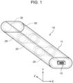
- Battery pack 10 according to an example of an embodiment will be described with reference to FIG. 1 .
- battery pack 10 a plurality of battery blocks 20 are housed in outer case 11 to match the device to be used.
- a plurality of batteries 30 (two batteries 30 in the example illustrated in FIG. 1 ) are fixed to each other by the holder and housed in outer case 11. With battery pack 10, it is relatively easy to exhaust, to the outside of the holder, the high-temperature internal gas exhausted from battery 30 when thermal runaway occurs in battery 30, as described in detail below.
- each structural element will be described with the longitudinal direction of battery 30 as a Z direction, the direction that is orthogonal to the Z direction and in which batteries 30 are aligned in battery block 20 as an X direction, and the direction that is orthogonal to the Z direction and the X direction as a Y direction.
- the side on which cap 45 (see FIG. 3 ) as a positive external terminal of battery 30 which is the top plate of sealing body 36 (see FIG. 3 ) is disposed is defined as one side, and the side opposite to the one side is defined as the other side.
- Battery pack 10 is mainly used as a motive power source.
- Battery pack 10 is used, for example, as a power source for an electric device driven by a motor, such as an electric vehicle, an electric power tool, an electric power-assisted bicycle, an electric motorcycle, an electric wheelchair, an electric tricycle, or an electric cart.
- a motor such as an electric vehicle, an electric power tool, an electric power-assisted bicycle, an electric motorcycle, an electric wheelchair, an electric tricycle, or an electric cart.
- the application of battery pack 10 is not limited to the above examples, and may be used as a power source for various electric devices used indoors and outdoors other than the motor-driven electric devices, such as a cleaner, a wireless device, a lighting device, a digital camera, or a video camera.
- Battery pack 10 includes: battery blocks 20 each of which houses a plurality of batteries 30; and outer case 11 that houses a plurality of battery blocks 20 (three battery blocks 20 in the example illustrated in FIG. 1 ).
- Each battery block 20 includes a plurality of batteries 30 arranged in alignment.
- Battery pack 10 includes a plurality of battery blocks 20 connected in series or parallel to output voltage corresponding to the device to be used.
- batteries 30 are electrically connected to each other.
- batteries 30 are connected to each other in series or in parallel.
- batteries 30 are connected in parallel. Details of battery blocks 20 and batteries 30 will be described below.
- Outer case 11 is made of metal, such as aluminum, and is cylindrical in shape. Outer case 11 is not limited to metal, but may be made of resin.
- the end of outer case 11 on the other side in the Z direction includes pack external terminal 12 that is electrically connected to battery block 20. Pack external terminal 12 is used as a terminal for supplying DC voltage when battery pack 10 is mounted on a device that is used with battery pack 10 mounted. Pack external terminal 12 is also used to charge battery pack 10.
- a lateral side of outer case 11 includes exhaust hole 13 (see FIG. 2 ) for exhausting, to the outside of battery pack 10, the high-temperature internal gas exhausted from battery 30 undergoing thermal runaway .
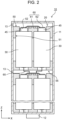
- Battery block 20 according to an example of the embodiment will be described with reference to FIG. 2 .
- Battery block 20 includes two batteries 30, first holder 50, current collector plate 60, second holder 55, and current collector lead 65.
- First holder 50 is a holder that holds one side of each battery 30 in the Z direction.
- Current collector plate 60 abuts one surface of first holder 50, and is connected to caps 45 each of which is the top plate of sealing body 36 (see FIG. 3 ) as a positive external terminal of battery 30 described below.
- Second holder 55 is a holder that holds the other side of each battery 30 in the Z direction.
- Current collector lead 65 is connected to the bottom portion of outer can 35 (see FIG. 3 ) as a negative external terminal of each battery 30.
- current collector plate 60 of battery block 20 positioned closest to the one side in the Z direction corresponds to the total positive charge.
- Current collector lead 65 of battery block 20 closest to the other side in the Z direction corresponds to the total negative charge.
- Current collector plate 60 and current collector leads 65 are electrically connected to pack external terminal 12 (not illustrated). Details of battery 30, first holder 50, and current collector plate 60 will be described below.
- Battery 30 is a cylindrical battery, and is a lithium-ion battery.
- Battery 30 is not limited to a cylindrical battery, but may also be a prismatic battery, laminated battery, or the like.
- Battery 30 may be an aqueous battery or a non-aqueous battery.
- a lithium-ion battery is preferably used as an example of the non-aqueous battery.
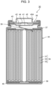
- battery 30 includes, on the one side in the Z direction, cap 45 as a positive external terminal which is the top plate of sealing body 36, as described in detail below.
- cap 45 When internal gas is generated in battery 30 during thermal runaway and the internal pressure increases, the internal gas is exhausted through exhaust hole 45A of cap 45. In other words, in battery 30, the internal gas is exhausted from the one side in the Z direction when the internal pressure increases.
- Battery 30 includes electrode body 34, an electrolyte (not illustrated), and outer can 35 that houses electrode body 34 and the electrolyte.
- Electrode body 34 includes positive electrode 31, negative electrode 32, and separator 33, and has a wound structure in which positive electrode 31 and negative electrode 32 are spirally wound via separator 33.
- Outer can 35 has a bottomed cylindrical shape in which an opening is provided on the one side in the Z direction. The opening of outer can 35 is blocked by sealing body 36.
- Battery 30 includes insulating plates 37 and 38 that are respectively positioned above and below electrode body 34.
- positive electrode lead 39 attached to positive electrode 31 extends toward sealing body 36 through a through-hole of insulating plate 37
- negative electrode lead 40 attached to negative electrode 32 extends over the outside of insulating plate 38 at the bottom portion of outer can 35.
- Positive electrode lead 39 is connected by welding or the like to the lower surface of internal terminal plate 41, which is the bottom plate of sealing body 36.
- Cap 45 which is the top plate of sealing body 36 electrically connected to internal terminal plate 41, serves as a positive external terminal.
- Negative electrode lead 40 is connected to the inner surface of the bottom portion of outer can 35 by welding or the like, and the bottom portion of outer can 35 serves as a negative external terminal.
- Sealing body 36 includes a stacked structure of internal terminal plate 41, lower valve body 42, insulating member 43, upper valve body 44, and cap 45, in order from the electrode body 34 side.
- Each structural element of sealing body 36 has a disk or ring shape, for example, and the structural elements excluding insulating member 43 are electrically connected to each other.
- the central portions of lower valve body 42 and upper valve body 44, which form a so-called gas exhaust valve, are connected to each other, and insulating member 43 is interposed between the peripheral portions of lower valve 42 and upper valve 44.
- First holder 50 holds the one side of each of two batteries 30 in the Z direction, as described above.
- the number of batteries 30 held by first holder 50 is not limited to the present embodiment.
- First holder 50 may be made of, for example, a high thermal conductivity PPS (polyphenylene sulfide) resin, a resin containing a heat dissipation filler, or an injection moldable thermosetting resin. More specifically, first holder 50 may be made of phenolic resin, unsaturated polyester, or unsaturated polyester mixed with a heat-absorbing agent. First holder 50 may be made of an inorganic mineral such as mica, or a resin material mixed with an inorganic mineral such as mica.
- PPS polyphenylene sulfide
- first holder 50 has an oval shape viewed from the Z direction, and has a predetermined thickness in the Z direction.
- First holder 50 includes housing portion 51 (see FIG. 2 ) that houses batteries 30, openings 52 each of which exposes cap 45 as a positive external terminal of battery 30, and grooves 53 that allow the internal gas to be exhausted to the outside of first holder 50 when the internal pressure of battery 30 increases. Details of grooves 53 will be described below.
- housing portion 51 is disposed on the surface of first holder 50 on the other side in the Z direction.
- Housing portion 51 is circular in shape when viewed from the other side in the Z direction, and is recessed when viewed from the X direction or the Y direction.
- the end portion of battery 30 on the one side in the Z direction is fitted to housing portion 51, so that the one side of battery 30 is held in place.
- each opening 52 penetrates through housing portion 51. More precisely, opening 52 is a circular hole with a diameter smaller than the circular diameter of housing portion 51 when viewed from the other side in the Z direction. However, the center of housing portion 51 and the center of opening 52 coincide with each other. Opening 52 allows cap 45 as the positive external terminal of battery 30 which is the top plate of sealing body 36 to be exposed, so that cap 45 and current collector plate 60 are connected to each other. In addition, opening 52 allows high-temperature internal gas exhausted from battery 30 during thermal runaway of battery 30 to be exhausted to the outside of first holder 50.
- current collector plate 60 abuts one surface of first holder 50 on the one side in the Z direction, and is connected to cap 45 as the positive external terminal of battery 30. More specifically, current collector plate 60 connects caps 45 as the positive external terminals of batteries 30 held in first holder 50 to each other.
- Current collector plate 60 is made of, for example, a metal plate, such as an aluminum plate, or a copper plate.
- Current collector plate 60 includes body 61 that abuts the one surface of first holder 50, and current collector leads 62 that are connected to caps 45.
- opening 52 that exposes cap 45 as the positive external terminal of first battery 30 is defined as first opening 52
- opening 52 that exposes cap 45 as the positive external terminal of second battery 30 is defined as second opening 52.
- body 61 abuts the one surface of first holder 50 between first opening 52 and second opening 52 of first holder 50.
- Body 61 is connected to, for example, current collector leads 65 connected to the negative terminals of another battery block 20 (not illustrated).
- Current collector leads 62 are formed continuously with body 61 at both ends of body 61 in the X direction, and are electrically connected to caps 45 by being welded and joined to caps 45.
- Grooves 53 are provided in the one surface of first holder 50 on the one side in the Z direction. Grooves 53 are provided in the one surface of first holder 50 on the one side in the Z direction, at the portion that abuts at least current collector plate 60. Grooves 53 being provided at the portion that abuts current collector plate 60 means that grooves 53 are provided at the portion where the one surface of first holder 50 overlaps with current collector plate 60 when viewed from the one side.
- grooves 53 being provided at the portion that abuts at least current collector plate 60 includes the case where grooves 53 are provided only at the portion that abuts current collector plate 60, and the case where grooves 53 are provided at both the portion that abuts current collector plate 60 and the portion that does not abut current collector plate 60. More specifically, groove 53 communicatively connects the portion of opening 52 blocked by current collector lead 62 with the portion of the one surface of first holder 50 that does not abut current collector plate 60. The portion of opening 52 blocked by current collector lead 62 is the space in opening 52, between current collector lead 62 and cap 45.
- groove 53 includes first straight portion 53A that extends in the X direction and second straight portion 53B that extends in the Y direction.
- First straight portion 53A is covered by current collector plate 60, and extends in a straight line along the X direction from the portion of opening 52 blocked by current collector lead 62 to terminal end portion 54.
- Terminal end portion 54 is positioned between first opening 52 and second opening 52, and abuts current collector plate 60.
- first straight portion 53A extends in a straight line along the X direction from the periphery of first opening 52 to terminal end portion 54.
- first straight portion 53A extends in a straight line along the X direction from the periphery of second opening 52 to terminal end portion 54.
- Second straight portion 53B is in communication with first straight portion 53A, and extends in a straight line along the Y direction from terminal end portion 54 of first straight portion 53A.
- Middle portion 53C of second straight portion 53B is covered by current collector plate 60, and both ends 53D of second straight portion 53B are exposed from current collector plate 60.
- the cross-sectional shape, length, width, and the number and the like of grooves 53 are not limited to the present embodiment.
- the internal gas exhausted from battery 30 during thermal runaway of battery 30 is exhausted to the outside of first holder 50 without being obstructed by current collector lead 62. This prevents the internal gas from flowing into first holder 50 when thermal runaway occurs in one of batteries 30 in battery block 20, and prevents thermal runaway from occurring in neighboring battery 30 held inside first holder 50. In other words, it is easy to avoid a sequential occurrence of thermal runaway.
- second holder 55 may include grooves 53.
- Battery pack 10 includes: batteries 30, first holder 50 (holder), and current collector plate 60.
- Each of batteries 30 includes, on one side of the battery in the Z direction (longitudinal direction), cap 45 (external terminal) as a positive external terminal that is the top plate of sealing body 36. Internal gas is exhausted from exhaust hole 45A of cap 45 when the internal pressure increases.
- First holder 50 holds the one side of each of batteries 30 that are arranged in alignment.
- First holder 50 includes opening 52 through which cap 45 is exposed.
- Current collector plate 60 abuts one surface of first holder 50, and is connected to cap 45 while blocking a portion of opening 52. At least a portion of the one surface of first holder 50 that abuts current collector plate 60 includes groove 53 for exhausting, to the outside of first holder 50, the internal gas exhausted from the portion of opening 52 blocked by current collector plate 60.
- the internal gas exhausted from battery 30 during thermal runaway of battery 30 passes through groove 53 and is exhausted to the outside of first holder 50 without being obstructed by current collector lead 62.
- first holder 70 includes a housing portion (not illustrated), openings 72, and grooves 73 for exhausting the internal gas to the outside of first holder 70 when the internal pressure of battery 30 increases. Since the housing portion and openings 72 are the same as housing portion 51 and openings 52 of first holder 50 described above, the descriptions of the housing portion and openings 72 are omitted. Details of grooves 73 will be described below.
- Current collector plate 80 abuts one surface of first holder 70, and is connected to caps 45 as the positive external terminals of batteries 30. More specifically, current collector plate 80 connects caps 45 as the positive external terminals of batteries 30 held in first holder 70 to each other.
- Current collector plate 80 is made of a metal plate, such as an aluminum plate, or a copper plate.
- Current collector plate 80 includes body 81 that abuts the one surface of first holder 70 on the one side in the Z direction, and current collector leads 82 that are connected to caps 45.
- Body 81 has a shape that is approximately identical to the oval shape of first holder 70 viewed from the Z direction, and abuts the one surface of first holder 70.
- Body 81 includes openings 83 at the positions corresponding to openings 72 of first holder 70.
- Body 81 is also connected to, for example, current collector leads 65 that are connected to the negative terminal of another battery block 20.
- the shape, size, and the like of body 81 are not limited to the present embodiment, and may be any shape, size, and the like as long as body 81 at least includes openings 72 in the one surface of first holder 70.
- Each current collector lead 82 extends from the edge of opening 83, and is electrically connected to cap 45 by being welded and joined to cap 45. Respective current collector leads 82 extend from the edges of openings 83 at the same phase position. In the present embodiment, each of current collector leads 82 extends from the edge of opening 83 on one side in the X-direction.
- a plurality of grooves 73 are provided in the one surface of first holder 70 on the one side in the Z direction. Each groove 73 is provided in the portion of the one surface of first holder 70 that abuts current collector plate 80. Each groove 73 communicatively connects the portion of opening 72 blocked by current collector lead 82 with the portion of adjacent opening 72 that is not blocked by current collector plate 80.
- Grooves 73 allow the internal gas exhausted from battery 30 during thermal runaway of battery 30 to be discharged to the outside of first holder 70 through adjacent opening 72 without being obstructed by current collector lead 82. This prevents a sequential occurrence of thermal runaway caused by, when thermal runaway occurs in one of batteries 30 in battery block 20, high-temperature internal gas flowing into first holder 70 and coming into contact with neighboring battery 30 held inside first holder 50 leading to the occurrence of thermal runaway in neighboring battery 30 held inside first holder 50.
Landscapes
- Chemical & Material Sciences (AREA)
- Chemical Kinetics & Catalysis (AREA)
- Electrochemistry (AREA)
- General Chemical & Material Sciences (AREA)
- Inorganic Chemistry (AREA)
- Battery Mounting, Suspending (AREA)
- Gas Exhaust Devices For Batteries (AREA)
- Connection Of Batteries Or Terminals (AREA)
Abstract
Description
- The present disclosure relates to a battery pack in which a plurality of batteries are housed.
- A battery pack includes a plurality of batteries housed in an outer case to match the device to be used. In the battery pack, the batteries arranged in alignment are held by a holder, and the batteries are electrically connected to each other by a current collector plate (for example, Patent Literature (PTL) 1).
- When thermal runaway occurs in a battery housed in the battery pack due to some abnormality, high-temperature internal gas is exhausted from the battery undergoing thermal runaway. The high-temperature internal gas coming into contact with batteries held in the same holder (hereafter, referred to as "neighboring batteries") may cause thermal runaway in the neighboring batteries, resulting in a sequential occurrence of thermal runaway. Therefore, it is necessary to ensure that the internal gas exhausted from a battery undergoing thermal runaway is exhausted to the outside of the holder without coming into contact with neighboring batteries.
- [PTL 1]
Japanese Unexamined Patent Application Publication No. 2022-002199 - A battery includes a gas exhaust valve on one side of the battery in the longitudinal direction. With this configuration, the internal pressure of the battery increases during thermal runaway and the gas exhaust valve is activated, exhausting the internal gas from the one side of the battery in the longitudinal direction. On the other hand, an external terminal may be disposed on the one side of the battery in the longitudinal direction. Therefore, an opening is provided in the holder that holds the one side of the battery in the longitudinal direction to expose the external terminal, and a current collector lead of a current collector plate is connected to the external terminal exposed from the opening.
- In the configuration described above, when the internal gas of the battery is exhausted, the internal gas is exhausted through the opening of the holder. However, since the current collector lead of the current collector plate partially blocks the opening, the exhausted gas may be partially obstructed by the current collector lead. In recent years, increased size and output in batteries have led to more wide-shaped current collector leads, so that the above trend has become more pronounced.
- At the portion of the opening of the holder where the exhaust gas is obstructed by the current collector lead, the exhaust of the internal gas to the outside of the holder is inhibited. As a result, high-temperature internal gas may flow into the holder and come into contact with the neighboring batteries, which may cause thermal runaway in neighboring batteries and lead to a sequential occurrence of thermal runaway.
- In view of the above, an object of the present disclosure is to provide a battery pack that is relatively easy to exhaust, to the outside of the holder, high-temperature internal gas exhausted from a battery when thermal runaway occurs in the battery.
- A battery pack according to the present disclosure includes: batteries, a holder, and a current collector plate. Each of the batteries includes an external terminal on one side of the battery in a longitudinal direction. An internal gas is exhausted from the one side when an internal pressure increases. The holder holds the one side of each of the batteries that are arranged in alignment. The holder includes an opening through which the external terminal is exposed. The current collector plate abuts one surface of the holder, and is connected to the external terminal while blocking a portion of the opening. At least a portion of the one surface of the holder that abuts the current collector plate includes a groove for exhausting, to an outside of the holder, the internal gas exhausted from the portion of the opening blocked by the current collector plate.
- With the battery pack according to the present disclosure, it is relatively easy to exhaust, to the outside of the holder, high-temperature internal gas exhausted from a battery when thermal runaway occurs in the battery.
-
- [
FIG. 1] FIG. 1 is a perspective view of a battery pack according to an example of an embodiment. - [
FIG. 2] FIG. 2 is a cross-sectional view of the battery pack according to the example of the embodiment. - [
FIG. 3] FIG. 3 is a cross-sectional view of a battery according to an example of the embodiment. - [
FIG. 4] FIG. 4 is a perspective view of a holder according to an example of the embodiment. - [
FIG. 5] FIG. 5 is a perspective view of a holder according to another example of the embodiment. - An exemplary embodiment of the present disclosure will be described in detail below. In the following description, specific shapes, materials, directions, numerical values, etc. are examples shown to facilitate understanding of the present disclosure, and may be changed as appropriate to suit uses, purposes, specifications, and the like.
-
Battery pack 10 according to an example of an embodiment will be described with reference toFIG. 1 . - In
battery pack 10, a plurality ofbattery blocks 20 are housed inouter case 11 to match the device to be used. In eachbattery block 20, a plurality of batteries 30 (twobatteries 30 in the example illustrated inFIG. 1 ) are fixed to each other by the holder and housed inouter case 11. Withbattery pack 10, it is relatively easy to exhaust, to the outside of the holder, the high-temperature internal gas exhausted frombattery 30 when thermal runaway occurs inbattery 30, as described in detail below. - In the following description, each structural element will be described with the longitudinal direction of
battery 30 as a Z direction, the direction that is orthogonal to the Z direction and in whichbatteries 30 are aligned inbattery block 20 as an X direction, and the direction that is orthogonal to the Z direction and the X direction as a Y direction. In the Z direction, the side on which cap 45 (seeFIG. 3 ) as a positive external terminal ofbattery 30 which is the top plate of sealing body 36 (seeFIG. 3 ) is disposed is defined as one side, and the side opposite to the one side is defined as the other side. -
Battery pack 10 is mainly used as a motive power source.Battery pack 10 is used, for example, as a power source for an electric device driven by a motor, such as an electric vehicle, an electric power tool, an electric power-assisted bicycle, an electric motorcycle, an electric wheelchair, an electric tricycle, or an electric cart. However, the application ofbattery pack 10 is not limited to the above examples, and may be used as a power source for various electric devices used indoors and outdoors other than the motor-driven electric devices, such as a cleaner, a wireless device, a lighting device, a digital camera, or a video camera. -
Battery pack 10 includes:battery blocks 20 each of which houses a plurality ofbatteries 30; andouter case 11 that houses a plurality of battery blocks 20 (threebattery blocks 20 in the example illustrated inFIG. 1 ). - Each
battery block 20 includes a plurality ofbatteries 30 arranged in alignment.Battery pack 10 includes a plurality ofbattery blocks 20 connected in series or parallel to output voltage corresponding to the device to be used. Inbattery block 20,batteries 30 are electrically connected to each other. Inbattery block 20,batteries 30 are connected to each other in series or in parallel. Inbattery block 20 according to the present embodiment, for example,batteries 30 are connected in parallel. Details ofbattery blocks 20 andbatteries 30 will be described below. -
Outer case 11 is made of metal, such as aluminum, and is cylindrical in shape.Outer case 11 is not limited to metal, but may be made of resin. The end ofouter case 11 on the other side in the Z direction includes packexternal terminal 12 that is electrically connected tobattery block 20. Packexternal terminal 12 is used as a terminal for supplying DC voltage whenbattery pack 10 is mounted on a device that is used withbattery pack 10 mounted. Packexternal terminal 12 is also used to chargebattery pack 10. A lateral side ofouter case 11 includes exhaust hole 13 (seeFIG. 2 ) for exhausting, to the outside ofbattery pack 10, the high-temperature internal gas exhausted frombattery 30 undergoing thermal runaway . -
Battery block 20 according to an example of the embodiment will be described with reference toFIG. 2 . -
Battery block 20 includes twobatteries 30,first holder 50,current collector plate 60,second holder 55, andcurrent collector lead 65.First holder 50 is a holder that holds one side of eachbattery 30 in the Z direction.Current collector plate 60 abuts one surface offirst holder 50, and is connected tocaps 45 each of which is the top plate of sealing body 36 (seeFIG. 3 ) as a positive external terminal ofbattery 30 described below.Second holder 55 is a holder that holds the other side of eachbattery 30 in the Z direction.Current collector lead 65 is connected to the bottom portion of outer can 35 (seeFIG. 3 ) as a negative external terminal of eachbattery 30. Of battery blocks 20 connected in series inbattery pack 10,current collector plate 60 ofbattery block 20 positioned closest to the one side in the Z direction corresponds to the total positive charge.Current collector lead 65 ofbattery block 20 closest to the other side in the Z direction corresponds to the total negative charge.Current collector plate 60 and current collector leads 65 are electrically connected to pack external terminal 12 (not illustrated). Details ofbattery 30,first holder 50, andcurrent collector plate 60 will be described below. -
Battery 30 according to an example of the embodiment will be described with reference toFIG. 2 andFIG. 3 . -
Battery 30 is a cylindrical battery, and is a lithium-ion battery.Battery 30 is not limited to a cylindrical battery, but may also be a prismatic battery, laminated battery, or the like.Battery 30 may be an aqueous battery or a non-aqueous battery. A lithium-ion battery is preferably used as an example of the non-aqueous battery. - As illustrated in
FIG. 3 ,battery 30 includes, on the one side in the Z direction, cap 45 as a positive external terminal which is the top plate of sealingbody 36, as described in detail below. When internal gas is generated inbattery 30 during thermal runaway and the internal pressure increases, the internal gas is exhausted throughexhaust hole 45A ofcap 45. In other words, inbattery 30, the internal gas is exhausted from the one side in the Z direction when the internal pressure increases. -
Battery 30 includes electrode body 34, an electrolyte (not illustrated), andouter can 35 that houses electrode body 34 and the electrolyte. Electrode body 34 includespositive electrode 31, negative electrode 32, andseparator 33, and has a wound structure in whichpositive electrode 31 and negative electrode 32 are spirally wound viaseparator 33. Outer can 35 has a bottomed cylindrical shape in which an opening is provided on the one side in the Z direction. The opening ofouter can 35 is blocked by sealingbody 36. -
Battery 30 includes insulatingplates FIG. 3 ,positive electrode lead 39 attached topositive electrode 31 extends toward sealingbody 36 through a through-hole of insulatingplate 37, andnegative electrode lead 40 attached to negative electrode 32 extends over the outside of insulatingplate 38 at the bottom portion ofouter can 35.Positive electrode lead 39 is connected by welding or the like to the lower surface of internalterminal plate 41, which is the bottom plate of sealingbody 36.Cap 45, which is the top plate of sealingbody 36 electrically connected to internalterminal plate 41, serves as a positive external terminal.Negative electrode lead 40 is connected to the inner surface of the bottom portion ofouter can 35 by welding or the like, and the bottom portion ofouter can 35 serves as a negative external terminal. - Sealing
body 36 includes a stacked structure of internalterminal plate 41,lower valve body 42, insulatingmember 43,upper valve body 44, andcap 45, in order from the electrode body 34 side. Each structural element of sealingbody 36 has a disk or ring shape, for example, and the structural elements excluding insulatingmember 43 are electrically connected to each other. The central portions oflower valve body 42 andupper valve body 44, which form a so-called gas exhaust valve, are connected to each other, and insulatingmember 43 is interposed between the peripheral portions oflower valve 42 andupper valve 44. - In the gas exhaust valve, when the internal pressure increases during thermal runaway of
battery 30,lower valve body 42 deforms to pushupper valve body 44 up towardcap 45 and breaks. This blocks the current path betweenlower valve body 42 andupper valve body 44. When the internal pressure further increases,upper valve body 44 breaks, so that the internal gas is exhausted throughexhaust hole 45A provided in the lateral surface of the protrusion ofcap 45. However, the configuration is not limited to the present embodiment, and it may be that a gas exhaust valve is provided in the bottom portion ofouter can 35 that is the other side in the Z direction, and the internal gas is exhausted from the other side in the Z direction when the internal pressure increases. -
First holder 50 andcurrent collector plate 60 according to an example of the embodiment will be described with reference toFIG. 2 andFIG. 4 . -
First holder 50 holds the one side of each of twobatteries 30 in the Z direction, as described above. The number ofbatteries 30 held byfirst holder 50 is not limited to the present embodiment. -
First holder 50 may be made of, for example, a high thermal conductivity PPS (polyphenylene sulfide) resin, a resin containing a heat dissipation filler, or an injection moldable thermosetting resin. More specifically,first holder 50 may be made of phenolic resin, unsaturated polyester, or unsaturated polyester mixed with a heat-absorbing agent.First holder 50 may be made of an inorganic mineral such as mica, or a resin material mixed with an inorganic mineral such as mica. - As illustrated in
FIG. 4 ,first holder 50 has an oval shape viewed from the Z direction, and has a predetermined thickness in the Z direction.First holder 50 includes housing portion 51 (seeFIG. 2 ) that housesbatteries 30,openings 52 each of which exposescap 45 as a positive external terminal ofbattery 30, andgrooves 53 that allow the internal gas to be exhausted to the outside offirst holder 50 when the internal pressure ofbattery 30 increases. Details ofgrooves 53 will be described below. - As illustrated in
FIG. 2 ,housing portion 51 is disposed on the surface offirst holder 50 on the other side in the Z direction.Housing portion 51 is circular in shape when viewed from the other side in the Z direction, and is recessed when viewed from the X direction or the Y direction. The end portion ofbattery 30 on the one side in the Z direction is fitted tohousing portion 51, so that the one side ofbattery 30 is held in place. - As illustrated in
FIG. 2 andFIG. 4 , each opening 52 penetrates throughhousing portion 51. More precisely, opening 52 is a circular hole with a diameter smaller than the circular diameter ofhousing portion 51 when viewed from the other side in the Z direction. However, the center ofhousing portion 51 and the center of opening 52 coincide with each other.Opening 52 allowscap 45 as the positive external terminal ofbattery 30 which is the top plate of sealingbody 36 to be exposed, so thatcap 45 andcurrent collector plate 60 are connected to each other. In addition, opening 52 allows high-temperature internal gas exhausted frombattery 30 during thermal runaway ofbattery 30 to be exhausted to the outside offirst holder 50. - As illustrated in
FIG. 4 ,current collector plate 60 abuts one surface offirst holder 50 on the one side in the Z direction, and is connected to cap 45 as the positive external terminal ofbattery 30. More specifically,current collector plate 60 connectscaps 45 as the positive external terminals ofbatteries 30 held infirst holder 50 to each other.Current collector plate 60 is made of, for example, a metal plate, such as an aluminum plate, or a copper plate.Current collector plate 60 includesbody 61 that abuts the one surface offirst holder 50, and current collector leads 62 that are connected tocaps 45. - Here, among two
batteries 30, opening 52 that exposescap 45 as the positive external terminal offirst battery 30 is defined asfirst opening 52, and opening 52 that exposescap 45 as the positive external terminal ofsecond battery 30 is defined assecond opening 52. In this case,body 61 abuts the one surface offirst holder 50 betweenfirst opening 52 andsecond opening 52 offirst holder 50.Body 61 is connected to, for example, current collector leads 65 connected to the negative terminals of another battery block 20 (not illustrated). Current collector leads 62 are formed continuously withbody 61 at both ends ofbody 61 in the X direction, and are electrically connected tocaps 45 by being welded and joined tocaps 45. - When the internal pressure of
battery 30 increases during thermal runaway ofbattery 30, the internal gas is exhausted fromexhaust hole 45A ofcap 45 and then exhausted from opening 52 offirst holder 50. However, since opening 52 is partially blocked bycurrent collector lead 62 ofcurrent collector plate 60, the internal gas to be exhausted may be partially obstructed bycurrent collector lead 62. - In the portion where the exhaust of the internal gas is obstructed by
current collector lead 62, the exhaust of the internal gas to the outside offirst holder 50 is inhibited. Therefore, high-temperature internal gas may flow intofirst holder 50 and come into contact with neighboringbattery 30 held insidefirst holder 50, which may cause thermal runaway in neighboringbattery 30 and lead to a sequential occurrence of thermal runaway. In view of the above, in the present embodiment, in the portion where the exhaust of the internal gas is obstructed bycurrent collector lead 62, the internal gas is exhausted to the outside offirst holder 50 bygrooves 53 described below. -
Grooves 53 are provided in the one surface offirst holder 50 on the one side in the Z direction.Grooves 53 are provided in the one surface offirst holder 50 on the one side in the Z direction, at the portion that abuts at leastcurrent collector plate 60.Grooves 53 being provided at the portion that abutscurrent collector plate 60 means thatgrooves 53 are provided at the portion where the one surface offirst holder 50 overlaps withcurrent collector plate 60 when viewed from the one side. Moreover,grooves 53 being provided at the portion that abuts at leastcurrent collector plate 60 includes the case wheregrooves 53 are provided only at the portion that abutscurrent collector plate 60, and the case wheregrooves 53 are provided at both the portion that abutscurrent collector plate 60 and the portion that does not abutcurrent collector plate 60. More specifically, groove 53 communicatively connects the portion of opening 52 blocked bycurrent collector lead 62 with the portion of the one surface offirst holder 50 that does not abutcurrent collector plate 60. The portion of opening 52 blocked bycurrent collector lead 62 is the space in opening 52, betweencurrent collector lead 62 andcap 45. - More specifically,
groove 53 includes firststraight portion 53A that extends in the X direction and secondstraight portion 53B that extends in the Y direction. - First
straight portion 53A is covered bycurrent collector plate 60, and extends in a straight line along the X direction from the portion of opening 52 blocked bycurrent collector lead 62 toterminal end portion 54.Terminal end portion 54 is positioned betweenfirst opening 52 andsecond opening 52, and abutscurrent collector plate 60. In other words, it can be said that firststraight portion 53A extends in a straight line along the X direction from the periphery offirst opening 52 toterminal end portion 54. Moreover, it can be said that firststraight portion 53A extends in a straight line along the X direction from the periphery ofsecond opening 52 toterminal end portion 54. Here, for example, when the internal gas is exhausted fromfirst battery 30, the internal gas is led to firststraight portion 53A. Sinceterminal end portion 54 is provided betweenfirst opening 52 andsecond opening 52, the internal gas led to firststraight portion 53A is exhausted to the outside offirst holder 50 without contactingsecond battery 30 throughsecond opening 52. - Second
straight portion 53B is in communication with firststraight portion 53A, and extends in a straight line along the Y direction fromterminal end portion 54 of firststraight portion 53A.Middle portion 53C of secondstraight portion 53B is covered bycurrent collector plate 60, and both ends 53D of secondstraight portion 53B are exposed fromcurrent collector plate 60. The cross-sectional shape, length, width, and the number and the like ofgrooves 53 are not limited to the present embodiment. - With
grooves 53, the internal gas exhausted frombattery 30 during thermal runaway ofbattery 30 is exhausted to the outside offirst holder 50 without being obstructed bycurrent collector lead 62. This prevents the internal gas from flowing intofirst holder 50 when thermal runaway occurs in one ofbatteries 30 inbattery block 20, and prevents thermal runaway from occurring in neighboringbattery 30 held insidefirst holder 50. In other words, it is easy to avoid a sequential occurrence of thermal runaway. - The position at which
groove 53 is provided is not limited to the present embodiment. For example, in the configuration in which a gas exhaust valve is provided in the bottom portion ofouter can 35 that is the other side in the Z direction and the internal gas is exhausted from the other side in the Z direction when the internal pressure increases,second holder 55 may includegrooves 53. -
Battery pack 10 according to the present disclosure includes:batteries 30, first holder 50 (holder), andcurrent collector plate 60. Each ofbatteries 30 includes, on one side of the battery in the Z direction (longitudinal direction), cap 45 (external terminal) as a positive external terminal that is the top plate of sealingbody 36. Internal gas is exhausted fromexhaust hole 45A ofcap 45 when the internal pressure increases.First holder 50 holds the one side of each ofbatteries 30 that are arranged in alignment.First holder 50 includesopening 52 through which cap 45 is exposed.Current collector plate 60 abuts one surface offirst holder 50, and is connected to cap 45 while blocking a portion ofopening 52. At least a portion of the one surface offirst holder 50 that abutscurrent collector plate 60 includesgroove 53 for exhausting, to the outside offirst holder 50, the internal gas exhausted from the portion of opening 52 blocked bycurrent collector plate 60. - With the configuration above, the internal gas exhausted from
battery 30 during thermal runaway ofbattery 30 passes throughgroove 53 and is exhausted to the outside offirst holder 50 without being obstructed bycurrent collector lead 62. This prevents high-temperature internal gas from flowing intofirst holder 50 when thermal runaway occurs in one ofbatteries 30 inbattery block 20. Therefore, it is possible to prevent the high-temperature internal gas from flowing intofirst holder 50 and coming into contact with neighboringbattery 30 held insidefirst holder 50, and preventing thermal runaway from occurring in neighboringbattery 30 held insidefirst holder 50. In other words, it is easy to avoid a sequential occurrence of thermal runaway. -
First holder 70 andcurrent collector plate 80 according to another example of the embodiment will be described with reference toFIG. 5 . - As illustrated in
FIG. 5 ,first holder 70 includes a housing portion (not illustrated),openings 72, andgrooves 73 for exhausting the internal gas to the outside offirst holder 70 when the internal pressure ofbattery 30 increases. Since the housing portion andopenings 72 are the same ashousing portion 51 andopenings 52 offirst holder 50 described above, the descriptions of the housing portion andopenings 72 are omitted. Details ofgrooves 73 will be described below. -
Current collector plate 80 abuts one surface offirst holder 70, and is connected tocaps 45 as the positive external terminals ofbatteries 30. More specifically,current collector plate 80 connectscaps 45 as the positive external terminals ofbatteries 30 held infirst holder 70 to each other.Current collector plate 80 is made of a metal plate, such as an aluminum plate, or a copper plate.Current collector plate 80 includesbody 81 that abuts the one surface offirst holder 70 on the one side in the Z direction, and current collector leads 82 that are connected tocaps 45. -
Body 81 has a shape that is approximately identical to the oval shape offirst holder 70 viewed from the Z direction, and abuts the one surface offirst holder 70.Body 81 includesopenings 83 at the positions corresponding toopenings 72 offirst holder 70.Body 81 is also connected to, for example, current collector leads 65 that are connected to the negative terminal of anotherbattery block 20. However, the shape, size, and the like ofbody 81 are not limited to the present embodiment, and may be any shape, size, and the like as long asbody 81 at least includesopenings 72 in the one surface offirst holder 70. - Each
current collector lead 82 extends from the edge of opening 83, and is electrically connected to cap 45 by being welded and joined to cap 45. Respective current collector leads 82 extend from the edges ofopenings 83 at the same phase position. In the present embodiment, each of current collector leads 82 extends from the edge of opening 83 on one side in the X-direction. - A plurality of grooves 73 (two
grooves 73 in the example illustrated inFIG. 5 ) are provided in the one surface offirst holder 70 on the one side in the Z direction. Eachgroove 73 is provided in the portion of the one surface offirst holder 70 that abutscurrent collector plate 80. Eachgroove 73 communicatively connects the portion of opening 72 blocked bycurrent collector lead 82 with the portion ofadjacent opening 72 that is not blocked bycurrent collector plate 80. -
Grooves 73 allow the internal gas exhausted frombattery 30 during thermal runaway ofbattery 30 to be discharged to the outside offirst holder 70 throughadjacent opening 72 without being obstructed bycurrent collector lead 82. This prevents a sequential occurrence of thermal runaway caused by, when thermal runaway occurs in one ofbatteries 30 inbattery block 20, high-temperature internal gas flowing intofirst holder 70 and coming into contact with neighboringbattery 30 held insidefirst holder 50 leading to the occurrence of thermal runaway in neighboringbattery 30 held insidefirst holder 50. - The present disclosure is not limited to the foregoing exemplary embodiment and variations, but various other modifications and alterations are of course possible within the scope of the claims of the present application.
-
- 10
- battery pack
- 11
- outer case
- 12
- pack external terminal
- 13
- exhaust hole
- 20
- battery block
- 30
- battery
- 31
- positive electrode
- 32
- negative electrode
- 33
- separator
- 34
- electrode body
- 35
- outer can
- 36
- sealing body
- 37
- insulating plate
- 38
- insulating plate
- 39
- positive electrode lead
- 40
- negative electrode lead
- 41
- internal terminal plate
- 42
- lower valve body
- 43
- insulating member
- 44
- upper valve body
- 45
- cap (positive electrode external terminal)
- 45A
- exhaust hole
- 50
- first holder
- 51
- housing portion
- 52, 72, 83
- opening
- 53
- groove
- 53A
- first straight portion
- 53B
- second straight portion
- 54
- terminal end portion
- 55
- second holder
- 60
- current collector plate
- 61
- body
- 62, 65, 82
- current collector lead
- 70
- first holder
- 73
- groove
- 80
- current collector plate
- 81
- body
Claims (3)
- A battery pack comprising:a plurality of batteries each of which includes an external terminal on one side of the battery in a longitudinal direction of the battery, the battery causing an internal gas to be exhausted from the one side when an internal pressure increases;a holder that holds the one side of each of the plurality of batteries that are arranged in alignment, the holder including an opening through which the external terminal is exposed; anda current collector plate that abuts one surface of the holder, and is connected to the external terminal while blocking a portion of the opening,wherein at least a portion of the one surface of the holder that abuts the current collector plate includes a groove for exhausting, to an outside of the holder, the internal gas exhausted from the portion of the opening blocked by the current collector plate.
- The battery pack according to claim 1,
wherein the groove communicatively connects the portion of the opening blocked by the current collector plate with a portion of the one surface of the holder that does not abut the current collector plate. - The battery pack according to claim 1,
wherein the groove communicatively connects the portion of the opening blocked by the current collector plate with a portion of an adjacent opening that is not blocked by the current collector plate, the adjacent opening being adjacent to the opening.
Applications Claiming Priority (2)
| Application Number | Priority Date | Filing Date | Title |
|---|---|---|---|
| JP2022118519 | 2022-07-26 | ||
| PCT/JP2023/024863 WO2024024422A1 (en) | 2022-07-26 | 2023-07-05 | Battery pack |
Publications (2)
| Publication Number | Publication Date |
|---|---|
| EP4564567A1 true EP4564567A1 (en) | 2025-06-04 |
| EP4564567A4 EP4564567A4 (en) | 2025-12-17 |
Family
ID=89706143
Family Applications (1)
| Application Number | Title | Priority Date | Filing Date |
|---|---|---|---|
| EP23846155.2A Pending EP4564567A4 (en) | 2022-07-26 | 2023-07-05 | BATTERY BLOCK |
Country Status (5)
| Country | Link |
|---|---|
| US (1) | US20250316832A1 (en) |
| EP (1) | EP4564567A4 (en) |
| JP (1) | JPWO2024024422A1 (en) |
| CN (1) | CN119318066A (en) |
| WO (1) | WO2024024422A1 (en) |
Cited By (1)
| Publication number | Priority date | Publication date | Assignee | Title |
|---|---|---|---|---|
| EP4611140A4 (en) * | 2022-10-26 | 2026-03-18 | Panasonic Energy Co Ltd | BATTERY PACK |
Family Cites Families (8)
| Publication number | Priority date | Publication date | Assignee | Title |
|---|---|---|---|---|
| ES2555652T3 (en) * | 2007-07-16 | 2016-01-07 | Lg Chem, Ltd. | Electrical connection element for secondary battery |
| JP2011249250A (en) * | 2010-05-29 | 2011-12-08 | Sanyo Electric Co Ltd | Battery pack |
| US9564619B2 (en) * | 2010-11-30 | 2017-02-07 | Panasonic Intellectual Property Management Co., Ltd. | Battery module which reduces noise on a signal line |
| JP6920661B2 (en) * | 2016-12-27 | 2021-08-18 | パナソニックIpマネジメント株式会社 | Battery module |
| KR102096983B1 (en) * | 2017-09-08 | 2020-04-03 | 주식회사 엘지화학 | Battery module with a structure to break a connector using venting gas |
| JP7346057B2 (en) * | 2019-03-28 | 2023-09-19 | パナソニックエナジー株式会社 | battery pack |
| JP7543005B2 (en) | 2020-06-22 | 2024-09-02 | パナソニックエナジー株式会社 | Battery pack |
| JPWO2023120437A1 (en) * | 2021-12-24 | 2023-06-29 |
-
2023
- 2023-07-05 US US18/868,219 patent/US20250316832A1/en active Pending
- 2023-07-05 EP EP23846155.2A patent/EP4564567A4/en active Pending
- 2023-07-05 CN CN202380045081.4A patent/CN119318066A/en active Pending
- 2023-07-05 JP JP2024536898A patent/JPWO2024024422A1/ja active Pending
- 2023-07-05 WO PCT/JP2023/024863 patent/WO2024024422A1/en not_active Ceased
Cited By (1)
| Publication number | Priority date | Publication date | Assignee | Title |
|---|---|---|---|---|
| EP4611140A4 (en) * | 2022-10-26 | 2026-03-18 | Panasonic Energy Co Ltd | BATTERY PACK |
Also Published As
| Publication number | Publication date |
|---|---|
| WO2024024422A1 (en) | 2024-02-01 |
| EP4564567A4 (en) | 2025-12-17 |
| JPWO2024024422A1 (en) | 2024-02-01 |
| CN119318066A (en) | 2025-01-14 |
| US20250316832A1 (en) | 2025-10-09 |
Similar Documents
| Publication | Publication Date | Title |
|---|---|---|
| EP2254176B1 (en) | Rechargeable battery | |
| US11843128B2 (en) | Cell module | |
| JP5055090B2 (en) | Battery module | |
| JP6091815B2 (en) | Secondary battery | |
| US8197962B2 (en) | Assembled battery and battery module | |
| US10916744B2 (en) | Battery block | |
| JP7296208B2 (en) | Secondary battery and assembled battery | |
| JP6491448B2 (en) | Secondary battery and battery module | |
| KR20150066077A (en) | Battery module | |
| JP4918242B2 (en) | Secondary battery | |
| WO2017081838A1 (en) | Battery pack | |
| EP4564567A1 (en) | Battery pack | |
| EP4629412A1 (en) | Battery pack | |
| US20220367967A1 (en) | Power storage module | |
| EP4614718A1 (en) | Power storage device | |
| US20260058273A1 (en) | Battery pack | |
| EP4564566A1 (en) | Battery pack | |
| KR20050095950A (en) | Electrodes assembly and secondary battery using the same | |
| EP4632914A1 (en) | Battery pack | |
| US20250357638A1 (en) | Battery pack | |
| WO2025115861A1 (en) | Electricity storage module | |
| KR20060022359A (en) | Electrode terminal and secondary battery and battery module using same | |
| WO2026069741A1 (en) | Secondary battery | |
| WO2022210136A1 (en) | Power storage module | |
| JP2014149916A (en) | Square secondary battery |
Legal Events
| Date | Code | Title | Description |
|---|---|---|---|
| STAA | Information on the status of an ep patent application or granted ep patent |
Free format text: STATUS: THE INTERNATIONAL PUBLICATION HAS BEEN MADE |
|
| PUAI | Public reference made under article 153(3) epc to a published international application that has entered the european phase |
Free format text: ORIGINAL CODE: 0009012 |
|
| STAA | Information on the status of an ep patent application or granted ep patent |
Free format text: STATUS: REQUEST FOR EXAMINATION WAS MADE |
|
| 17P | Request for examination filed |
Effective date: 20241216 |
|
| AK | Designated contracting states |
Kind code of ref document: A1 Designated state(s): AL AT BE BG CH CY CZ DE DK EE ES FI FR GB GR HR HU IE IS IT LI LT LU LV MC ME MK MT NL NO PL PT RO RS SE SI SK SM TR |
|
| DAV | Request for validation of the european patent (deleted) | ||
| DAX | Request for extension of the european patent (deleted) | ||
| A4 | Supplementary search report drawn up and despatched |
Effective date: 20251119 |
|
| RIC1 | Information provided on ipc code assigned before grant |
Ipc: H01M 50/367 20210101AFI20251113BHEP Ipc: H01M 50/213 20210101ALI20251113BHEP Ipc: H01M 50/244 20210101ALI20251113BHEP Ipc: H01M 50/35 20210101ALI20251113BHEP Ipc: H01M 50/505 20210101ALI20251113BHEP Ipc: H01M 50/358 20210101ALI20251113BHEP |