EP4564545A1 - Cover plate assembly, battery cell, and battery pack - Google Patents
Cover plate assembly, battery cell, and battery pack Download PDFInfo
- Publication number
- EP4564545A1 EP4564545A1 EP23218039.8A EP23218039A EP4564545A1 EP 4564545 A1 EP4564545 A1 EP 4564545A1 EP 23218039 A EP23218039 A EP 23218039A EP 4564545 A1 EP4564545 A1 EP 4564545A1
- Authority
- EP
- European Patent Office
- Prior art keywords
- metal layer
- metal
- cover plate
- layer
- plate assembly
- Prior art date
- Legal status (The legal status is an assumption and is not a legal conclusion. Google has not performed a legal analysis and makes no representation as to the accuracy of the status listed.)
- Pending
Links
Images


Classifications
-
- H—ELECTRICITY
- H01—ELECTRIC ELEMENTS
- H01M—PROCESSES OR MEANS, e.g. BATTERIES, FOR THE DIRECT CONVERSION OF CHEMICAL ENERGY INTO ELECTRICAL ENERGY
- H01M50/00—Constructional details or processes of manufacture of the non-active parts of electrochemical cells other than fuel cells, e.g. hybrid cells
- H01M50/10—Primary casings; Jackets or wrappings
- H01M50/147—Lids or covers
- H01M50/148—Lids or covers characterised by their shape
- H01M50/152—Lids or covers characterised by their shape for cells having curved cross-section, e.g. round or elliptic
-
- H—ELECTRICITY
- H01—ELECTRIC ELEMENTS
- H01M—PROCESSES OR MEANS, e.g. BATTERIES, FOR THE DIRECT CONVERSION OF CHEMICAL ENERGY INTO ELECTRICAL ENERGY
- H01M10/00—Secondary cells; Manufacture thereof
- H01M10/04—Construction or manufacture in general
-
- H—ELECTRICITY
- H01—ELECTRIC ELEMENTS
- H01M—PROCESSES OR MEANS, e.g. BATTERIES, FOR THE DIRECT CONVERSION OF CHEMICAL ENERGY INTO ELECTRICAL ENERGY
- H01M50/00—Constructional details or processes of manufacture of the non-active parts of electrochemical cells other than fuel cells, e.g. hybrid cells
- H01M50/10—Primary casings; Jackets or wrappings
- H01M50/147—Lids or covers
- H01M50/148—Lids or covers characterised by their shape
-
- H—ELECTRICITY
- H01—ELECTRIC ELEMENTS
- H01M—PROCESSES OR MEANS, e.g. BATTERIES, FOR THE DIRECT CONVERSION OF CHEMICAL ENERGY INTO ELECTRICAL ENERGY
- H01M50/00—Constructional details or processes of manufacture of the non-active parts of electrochemical cells other than fuel cells, e.g. hybrid cells
- H01M50/10—Primary casings; Jackets or wrappings
- H01M50/172—Arrangements of electric connectors penetrating the casing
- H01M50/174—Arrangements of electric connectors penetrating the casing adapted for the shape of the cells
- H01M50/179—Arrangements of electric connectors penetrating the casing adapted for the shape of the cells for cells having curved cross-section, e.g. round or elliptic
-
- H—ELECTRICITY
- H01—ELECTRIC ELEMENTS
- H01M—PROCESSES OR MEANS, e.g. BATTERIES, FOR THE DIRECT CONVERSION OF CHEMICAL ENERGY INTO ELECTRICAL ENERGY
- H01M50/00—Constructional details or processes of manufacture of the non-active parts of electrochemical cells other than fuel cells, e.g. hybrid cells
- H01M50/50—Current conducting connections for cells or batteries
- H01M50/543—Terminals
- H01M50/552—Terminals characterised by their shape
- H01M50/559—Terminals adapted for cells having curved cross-section, e.g. round, elliptic or button cells
-
- H—ELECTRICITY
- H01—ELECTRIC ELEMENTS
- H01M—PROCESSES OR MEANS, e.g. BATTERIES, FOR THE DIRECT CONVERSION OF CHEMICAL ENERGY INTO ELECTRICAL ENERGY
- H01M50/00—Constructional details or processes of manufacture of the non-active parts of electrochemical cells other than fuel cells, e.g. hybrid cells
- H01M50/50—Current conducting connections for cells or batteries
- H01M50/543—Terminals
- H01M50/562—Terminals characterised by the material
-
- H—ELECTRICITY
- H01—ELECTRIC ELEMENTS
- H01M—PROCESSES OR MEANS, e.g. BATTERIES, FOR THE DIRECT CONVERSION OF CHEMICAL ENERGY INTO ELECTRICAL ENERGY
- H01M50/00—Constructional details or processes of manufacture of the non-active parts of electrochemical cells other than fuel cells, e.g. hybrid cells
- H01M50/50—Current conducting connections for cells or batteries
- H01M50/543—Terminals
- H01M50/564—Terminals characterised by their manufacturing process
- H01M50/566—Terminals characterised by their manufacturing process by welding, soldering or brazing
-
- H—ELECTRICITY
- H01—ELECTRIC ELEMENTS
- H01M—PROCESSES OR MEANS, e.g. BATTERIES, FOR THE DIRECT CONVERSION OF CHEMICAL ENERGY INTO ELECTRICAL ENERGY
- H01M50/00—Constructional details or processes of manufacture of the non-active parts of electrochemical cells other than fuel cells, e.g. hybrid cells
- H01M50/10—Primary casings; Jackets or wrappings
- H01M50/147—Lids or covers
- H01M50/148—Lids or covers characterised by their shape
- H01M50/15—Lids or covers characterised by their shape for prismatic or rectangular cells
-
- Y—GENERAL TAGGING OF NEW TECHNOLOGICAL DEVELOPMENTS; GENERAL TAGGING OF CROSS-SECTIONAL TECHNOLOGIES SPANNING OVER SEVERAL SECTIONS OF THE IPC; TECHNICAL SUBJECTS COVERED BY FORMER USPC CROSS-REFERENCE ART COLLECTIONS [XRACs] AND DIGESTS
- Y02—TECHNOLOGIES OR APPLICATIONS FOR MITIGATION OR ADAPTATION AGAINST CLIMATE CHANGE
- Y02E—REDUCTION OF GREENHOUSE GAS [GHG] EMISSIONS, RELATED TO ENERGY GENERATION, TRANSMISSION OR DISTRIBUTION
- Y02E60/00—Enabling technologies; Technologies with a potential or indirect contribution to GHG emissions mitigation
- Y02E60/10—Energy storage using batteries
Definitions
- the disclosure relates to the technical field of battery cells, and particularly relates to a cover plate assembly, a battery cell, and a battery pack.
- the inventor knows a way to connect a battery cell to an external electrical connection member through an outer conductive member in the battery cell.
- the outer conductive member is generally composed of a copper plate and an aluminum plate.
- the copper plate and the aluminum plate are fixedly connected through riveting, but in this way, a gap is likely to exist at a connection between the copper plate and the aluminum plate, which causes the connection to be unreliable.
- the objective of the disclosure is to provide a cover plate assembly and a battery cell to improve the current manner of fixing a copper plate and an aluminum plate in an outer conductive member of a battery cell through riveting such that a gap is likely to exist at a connection between the copper plate and the aluminum plate, which causes the connection to be unreliable.
- the disclosure provides a cover plate assembly, which includes a cover plate body, an outer conductive member, and an electrode lead-out member.
- the cover plate body is provided with a through hole.
- the outer conductive member is disposed on a side of the cover plate body away from an electrode assembly.
- the outer conductive member includes a first metal layer, a second metal layer, and a third metal layer disposed between the first metal layer and the second metal layer.
- the first metal layer includes a first metal
- the second metal layer includes a second metal
- the third metal layer includes a third metal.
- the third metal layer is respectively connected to the first metal layer and the second metal layer to form a first composite layer and a second composite layer.
- the first composite layer includes the first metal and the third metal.
- the second composite layer includes the second metal and the third metal.
- the electrode lead-out member passes through the through hole and is electrically connected to the outer conductive member.
- a content of the first metal in the first composite layer increases in a direction away from the first metal layer toward the first metal layer.
- a content of the second metal in the second composite layer increases in a direction away from the second metal layer toward the second metal layer.
- the content of the second metal in the second composite layer is greater than the content of the first metal in the first composite layer.
- the third metal layer covers at least a part of a surface of the first metal layer close to the second metal layer or a part of a surface of the second metal layer close to the first metal layer.
- the third metal layer completely covers one with a larger area of the surface of the first metal layer close to the second metal layer and the surface of the second metal layer close to the first metal layer, and the third metal layer evenly covers the surface of the first metal layer close to the second metal layer or the surface of the second metal layer close to the first metal layer.
- a surface of one of the first metal layer and the second metal layer close to other one of the first metal layer and the second metal layer is provided with at least one protrusion
- a surface of the other one of the first metal layer and the second metal layer close to the one of the first metal layer and the second metal layer is provided with a first fitting hole corresponding to the at least one protrusion
- the third metal layer is provided with a second fitting hole corresponding to the at least one protrusion
- the at least one protrusion is fittingly connected to the corresponding first fitting hole and second fitting hole.
- a surface of the first metal layer close to the second metal layer is provided with the at least one protrusion
- a surface of the second metal layer close to the first metal layer is provided with the first fitting hole fitted to the at least one protrusion
- the third metal layer is provided with the second fitting hole fitted to the at least one protrusion
- the at least one protrusion is fittingly connected to the corresponding first fitting hole and second fitting hole.
- the at least one protrusion is symmetrically distributed on one of the first metal layer and the second metal layer along a central axis of the outer conductive member
- the first fitting holes are symmetrically distributed on other one of the first metal layer and the second metal layer along the central axis of the outer conductive member
- the second fitting holes are symmetrically distributed on the third metal layer along the central axis of the outer conductive member.
- an outer surface of the at least one protrusion or an inner surface of the first fitting hole is covered with the third metal layer.
- a part of a surface of the second metal layer close to the first metal layer that exceeds the first metal layer is not covered with the third metal layer, and a thickness of the third metal layer is set between 0.5 ⁇ m and 1000 ⁇ m.
- the thickness of the third metal layer is set between 5 ⁇ m and 10 ⁇ m.
- a thickness of the second composite layer is d
- a total thickness of the first composite layer and the second composite layer is a
- a relational expression 0.2a ⁇ d ⁇ 0.9a is satisfied
- the third metal layer includes at least one of nickel, silver, and tin.
- the disclosure also provides a battery cell, including the cover plate assembly according to any one of the above embodiments.
- the disclosure also provides a shell, installed with the electrode assembly.
- An end of the electrode lead-out member in the cover plate assembly is connected to the electrode assembly, and other end passes through the through hole and is electrically connected to the second metal layer in the cover plate assembly.
- the disclosure also provides a battery pack, including the battery cell.
- the disclosure provides the cover plate assembly, the battery cell, and the battery pack.
- the third metal layer respectively forms the first composite layer including the first metal and the third metal with the first metal layer and forms the second composite layer including the second metal and the third metal with the second metal layer. That is, the metal composite layers are formed at the contact positions of the third metal layer and the first metal layer and the second metal layer to ensure the reliability and stability of the connection between the first metal layer and the second metal layer, and the third metal layer can fill the gap between the first metal layer and the second metal layer to further improve the reliability and stability of the connection between the first metal layer and the second metal layer.
- the disclosure provides a cover plate assembly, a battery cell, and a battery pack.
- the inventor knows a way to connect a battery cell to an external electrical connection member through an outer conductive member in the battery cell.
- the outer conductive member is generally made of a copper-aluminum composite plate or is formed by connecting a copper layer and an aluminum layer through adopting friction welding.
- the solution of adopting the composite plate has the issues of high raw material cost and complex process, and low material utilization during production. Adopting the friction welding has the issues of complex process, large machining volume, low material utilization, and extremely high cost.
- the copper plate and the aluminum plate are fixedly connected through riveting to form the outer conductive member, but in this way, a gap is likely to exist at a connection between the copper plate and the aluminum plate, which causes the connection to be unreliable. Please refer to FIG. 1 .
- brazing is added between the copper plate and the aluminum plate.
- solder may easily overflow from sides of a first metal layer 21 and a second metal layer 22 and/or overflow from a gap between a protrusion 201 and a first fitting hole 202, thereby affecting other processes, and when too little is applied, there is still a gap between adjacent surfaces of copper and aluminum and/or between the protrusion 201 and the first fitting hole 202, such that the contact area is too small and the strength is difficult to be ensured. Also, the uniformity of the solder may easily cause a riveting post on the aluminum to slightly protrude, leading to the issue of poor high consistency.
- a cover plate assembly 100 includes a cover plate body 10, an outer conductive member 20, and an electrode lead-out member.
- the cover plate body 10 is provided with a through hole, the outer conductive member 20 is disposed on a side of the cover plate body 10 away from an electrode assembly, and the electrode lead-out member passes through the through hole and is connected to the outer conductive member 20.
- the outer conductive member 20 includes a first metal layer 21, a second metal layer 22, and a third metal layer 23.
- the first metal layer 21 includes a first metal
- the second metal layer 22 includes a second metal
- the third metal layer 23 includes a third metal.
- the third metal layer 23 is disposed between the first metal layer 21 and the second metal layer 22, and the third metal layer 23 is respectively connected to the first metal layer 21 and the second metal layer 22 to form a first composite layer and a second composite layer, wherein the first composite layer includes the first metal and the third metal, and the second composite layer includes the second metal and the third metal.
- first metal layer 21, the second metal layer 22, and the third metal layer 23 are bonded together through hot pressing. During the hot pressing, surfaces of the first metal layer 21 and the second metal layer 22 are evenly stressed, thereby further ensuring the high consistency of the outer conductive member 20.
- outer conductive member 20 is preferably a negative conductive member of the battery cell.
- the third metal layer 23 is fixedly connected to the first metal layer 21 and the second metal layer 22 through hot pressing to form the first composite layer and the second composite layer, and the hot pressing thereof enables a stable connection between the first metal layer 21 and the second metal layer 22, the bonding surfaces are larger, and the hot pressing manner enables contact positions of the first metal layer 21 and the third metal layer 21 to be partially fused together to form a metal composite section, thereby forming the composite layer.
- the contact positions of the second metal layer 22 and the third metal layer 23 are partially fused to form a part of the metal composite section to improve the hot pressing effect and enable the third metal layer 23 to fill the gap between the first metal layer 21 and the second metal layer 22, thereby ensuring the reliability and stability of the connection between the first metal layer 21 and the second metal layer 22.
- the first metal layer 21 is an aluminum layer
- the second metal layer 22 is a copper layer
- the third metal layer 23 is at least one of nickel, silver, and tin, preferably nickel, so that the third metal layer 23 can prevent the first metal layer 21 and the second metal layer 22 from being oxidized and corroded.
- the content of the first metal in the first composite layer increases in a direction away from the first metal layer 21 toward the first metal layer 21, that is, the content of the first metal increases along a direction from the second metal layer 22 toward the first metal layer 21 to enable a good transition between the first metal layer 21 and the third metal layer 23, and ensure a reliable connection between the first metal layer 21 and the third metal layer 23; and/or the content of the second metal in the second composite layer increases in a direction away from the second metal layer 22 toward the second metal layer 22, that is, the content of the second metal is increases along a direction from the first metal layer 21 toward the second metal layer 22 to enable a good transition between the second metal layer 22 and the third metal layer 23, and ensure a reliable connection between the second metal layer 22 and the third metal layer 23, thereby ensuring the stability of the overall structure of the outer conductive member 20. Further, the content of the second metal in the second composite layer is greater than the content of the first metal in the first composite layer to ensure a reliable connection between the first metal layer 21 and the third metal layer 23, and ensure a
- the outer conductive member 20 may be made by first processing the first metal layer 21 and the second metal layer 22 into a single component, and then fixedly connecting the first metal layer 21, the second metal layer 22, and the third metal layer 23 through hot pressing.
- the first metal layer 21, the second metal layer 22, and the third metal layer 23 may be fixedly connected through hot pressing, and then processed to form the outer conductive member 20.
- first metal layer 21, the second metal layer 22, and the third metal layer 23 may be separately processed and formed, and then connected to form the outer conductive member 20, or the first metal layer 21, the second metal layer 22, and the third metal layer 23 may be connected and formed, and then processed to form the outer conductive member 20, which can reduce the difficulty of manufacturing, and each component may be separately processed and formed to prevent material waste, which can improve material utilization to reduce material cost.
- the connection process between the first metal layer 21, the second metal layer 22, and the third metal layer 23 may be to first fixedly connect the third metal layer 23 to one of the first metal layer 21 and the second metal layers 22, and then fixedly connect to the other one.
- the third metal layer 23 covers at least a part of a surface of the first metal layer 21 close to the second metal layer 22 or a part of a surface of the second metal layer 22 close to the first metal layer 21, that is, a partial region of the adjacent surface of the first metal layer 21 or the second metal layer 22 is covered with the third metal layer 22, so that the region covered with the third metal layer 23 forms the composite layer after hot pressing to ensure the reliable connection between the first metal layer 21 and the second metal layer 22 after hot pressing and fixing.
- the third metal layer 23 completely covers the surface with a larger area among the surface of the first metal layer 21 close to the second metal layer 22 and the surface of the second metal layer 22 close to the first metal layer 21 to ensure that the third metal layer 23 can completely fill the gap between the two opposite surfaces of the first metal layer 21 and the second metal layer 22 after hot pressing and ensure that the connection area between the first metal layer 21 and the second metal layer 22 is large enough, thereby ensuring the conductive properties of the outer conductive member 20 and improving the reliability of the connection between the first metal layer 21 and the second metal layer 22.
- the third metal layer 23 evenly covers the surface of the first metal layer 21 close to the second metal layer 22 or the surface of the second metal layer 22 close to the first metal layer 21.
- the third metal layer 23 affecting the hot pressing effect caused by uneven thickness of the third metal layer 23 can be prevented, thereby improving the reliability of the connection between the first metal layer 21 and the second metal layer 22 while preventing the issue of the height inconsistency of the outer conductive member 20 caused by the uneven thickness of the third metal layer 23 on the surface of the first metal layer 21 or the surface of the second metal layer 22 to improve the height consistency of the outer conductive member 20, thereby facilitating the connection of the outer conductive member 20 with other structures.
- the third metal layer 23 evenly covers the surface of the first metal layer 21 to form an integrated structure with the first metal layer 21 or the surface of the second metal layer 22 to form an integrated structure with the second metal layer 22 through electroplating.
- the third metal layer 23 may also evenly cover the first metal layer 21 or the second metal layer 22 through spraying.
- a surface of one of the first metal layer 21 and the second metal layer 22 close to the other one is provided with at least one protrusion 201
- a surface of the other one close to the one is provided with a first fitting hole 202 corresponding to the at least one protrusion 201
- the third metal layer 23 is provided with a second fitting hole 203 corresponding to the protrusion 201.
- the at least one protrusion 201 is fittingly connected to the corresponding first fitting hole 202 and second fitting hole 203.
- the surface of the first metal layer 21 close to the second metal layer 22 is provided with multiple protrusions 201, and the protrusions 201 are evenly spaced on the first metal layer 21 along a circumferential direction thereof.
- the second metal layer 22 is provided with multiple first fitting holes 202 fitted to the protrusions 201
- the third metal layer 23 is provided with the second fitting holes 203 fitted to the protrusions 201.
- the protrusions 201 are fittingly connected to the corresponding first fitting holes 202 and second fitting holes 203, which further improves the reliability and stability of the connection between the first metal layer 21 and the second metal layer 22 through the riveting of the protrusions and the fitting holes.
- the third metal layer 23 is respectively connected to the first metal layer 21 and the second metal layer 22 to form the first composite layer and the second composite layer.
- the protrusions 201 may be synchronously pressed into the first fitting holes 202 and the second fitting holes 203 to implement the reliable connection between the first metal layer 21 and the second metal layer 22, that is, the two processes of hot pressing connection and riveting are implemented through one process, which reduces the difficulty of manufacturing to increase the production capacity and save cost.
- the protrusions 201 are symmetrically distributed on one of the first metal layer 21 and the second metal layer 22 along a central axis L of the outer conductive member 20
- the first fitting holes 202 are symmetrically distributed on the other one of the first metal layer 21 and the second metal layer 22 along the central axis L of the outer conductive member 20
- the second fitting holes 203 are symmetrically distributed on the third metal layer 23 along the central axis L of the outer conductive member 20.
- the protrusions 201, the first fitting holes 202, and the second fitting holes 203 are symmetrically distributed along the central axis L of the outer conductive member 20, so that when the first metal layer 21, the second metal layer 22, and the third metal layer 23 are fittingly connected, the protrusions 201 and the first fitting holes 202 and the second fitting holes 203 are fittingly connected to facilitate riveting.
- the symmetrical distribution along the central axis L enables the first metal layer 21, the second metal layer 22, and the third metal layer 23 to be evenly stressed at each position when connected, thereby improving the stability and reliability of the connection between the metal layers.
- an outer surface of the protrusion 201 or an inner surface of the first fitting hole 202 is covered with the third metal layer 23, that is, in addition to covering the two opposite surfaces of the first metal layer 21 and the second metal layer 22, the third metal layer 23 also covers between the protrusion 201 and the first fitting hole 202, so that the third metal layer 23 can fill a gap between the protrusion 201 and the first fitting hole 202 after hot pressing and riveting to improve the riveting effect to further ensure the reliable connection between the first metal layer 21 and the second metal layer 22.
- FIG. 2 and FIG. 4 Please refer to FIG. 2 and FIG. 4 .
- a part of the surface of the second metal layer 22 close to the first metal layer 21 that exceeds the first metal layer 21 is not covered with the third metal layer 23, and the part not covered with the third metal layer 23 is connected to the electrode lead-out member, for example, through welding. Since the part is not covered with the third metal layer 23, the electrode lead-out member is directly welded to the second metal layer 22, thereby ensuring the stability and reliability of the welding between the electrode lead-out member and the second metal layer 22.
- the thickness of the third metal layer 23 is set between 0.5 ⁇ m and 1000 ⁇ m. In practice, it is found that if the thickness is lower than 0.5 um, it will easily cause the third metal layer 23 to be unable to completely fill the gap between the first metal layer 21 and the second metal layer 22 during hot pressing, which affects the reliability of the connection between the first metal layer 21 and the second metal layer 22, and if the thickness is higher than 1000 um, it will easily affect the hot pressing effect between the first metal layer 21, the second metal layer 22, and the third metal layer during hot pressing, which affects the reliability of the connection between the first metal layer 21 and the second metal layer 22, and there may be a thicker metal section between the first metal layer 21 and the second metal layer 22 after hot pressing, thereby easily affecting the overall conductive properties of the outer conductive member 20.
- the thickness of the third metal layer 23 is set between 0.5 ⁇ m and 1000 ⁇ m, so that the third metal layer 23 can completely fill the gap between the first metal layer 21 and the second metal layer 22, and the hot pressing effect during hot pressing can also be ensured, thereby ensuring that the composite layer with sufficient thickness can be smoothly formed to ensure the reliability of the connection between the first metal layer 21 and the second metal layer 22, and also ensure the overall conductive properties of the outer conductive member 20. Furthermore, the thickness of the third metal layer 23 is set between 5 ⁇ m and 10 ⁇ m.
- the thickness is lower than 5 ⁇ m, it will easily cause the inability to form the composite layer with sufficient thickness during hot pressing to affect the reliability of the connection between the first metal layer 21 and the second metal layer 22, and if the thickness is higher than 10 um, it will easily affect the overall thickness of the outer conductive member 20, which causes the surface of the outer conductive member 20 to protrude too high relative to the cover plate body 10, thereby affecting the subsequent connection between the outer conductive member 20 and other structures, and the assembly of the battery cell.
- the thickness of the third metal layer 23 is set between 5 ⁇ m and 10 ⁇ m to ensure the formation of the composite layer with sufficient thickness, so that the connection between the first metal layer 21 and the second metal layer 22 is reliable, and the height of the outer conductive member 20 can also be prevented from being too high, thereby ensuring that the subsequent connection between the outer conductive member 20 and other structures, and the assembly of the battery cell can be smoothly performed.
- the thickness of the second composite layer is d
- the total thickness of the first composite layer and the second composite layer is a
- the thickness of the second composite layer and the total thickness satisfy the relational expression 0.2a ⁇ d ⁇ 0.9a, thereby ensuring the formation of the composite layer with sufficient thickness, so that the third metal layer 22 is reliably connected between the first metal layer 21 and the second metal layer 22 after hot pressing.
- the outer conductive member 20 is, for example, obtained through the following process.
- the first metal layer 21 and the second metal layer 22 are respectively processed into the required shapes.
- the third metal layer 23 is plated on the surface of the first metal layer 21 close to the second metal layer 22 or the surface of the second metal layer 22 close to the first metal layer 21 to facilitate the combination of the two.
- the first metal layer 21 and the second metal layer 22 are fitted together.
- the fitted first metal layer 21 and second metal layer 22 are placed on a hot press for hot pressing.
- a briquette is raised to a certain temperature and then moved downward, so that the briquette contacts and extrudes the surfaces of the first metal layer 21 and the second metal layer 22.
- the third metal layer 23 respectively forms the composite layers with first metal layer 21 and the second metal layer 22, and the protrusion 201 may be synchronously riveted into the first fitting hole 202 to complete the processing of the outer conductive member 20.
- the two processes of hot pressing connection and riveting are implemented through one process, which reduces the difficulty of manufacturing to increase the production capacity and save cost.
- the briquette contacting the first metal layer 21 and the second metal layer 22 may be made of a material with high hardness or high thermal conductivity such as graphite, and the temperature of the briquette respectively corresponding to the first metal layer 21 and the second metal layer 22 should be lower than the melting point thereof, so that the third metal layer 23 may be combined with the first metal layer 21 and the second metal layer 22 to form the composite layers.
- a residual area of the third metal layer 23 electroplated on one of the first metal layer 21 and the second metal layer 22 remaining on the other one of the first metal layer 21 and the second metal layer 22 is S1
- the area of the third metal layer 23 is S2
- the area S1 and the area S2 satisfy the relational expression 0.352 ⁇ S1 ⁇ S2.
- the residual area S1 and the third metal layer area S2 satisfy the relational expression 0.652 ⁇ S1 ⁇ 0.952.
- the third metal layer 23 is electroplated on the surface of the second metal layer 22. After being peeled off, a part of the third metal layer 23 is adhered onto the first metal layer 21.
- the residual area S1 of the third metal layer 23 on the first metal layer 21 is set between 0.3 S2 and S2 to ensure that the third metal layer 23 and the first metal layer 22 and the second metal layer 22 are firmly fused and connected together during hot pressing, thereby improving the reliability and stability of the connection between the first metal layer 21 and the second metal layer 22.
- the disclosure also provides a battery cell, which includes the cover plate assembly 100 and a shell.
- An electrode assembly is installed in the shell.
- One end of an electrode lead-out member in the cover plate assembly 100 is connected to the electrode assembly, and the other end passes through a through hole and is electrically connected to the second metal layer 22 of the cover plate assembly 100.
- the cover plate body 10 is provided with the through hole and is surrounded by a groove 102 and an outer support member 103.
- the outer support member 103 is disposed around the outer periphery of the outer conductive member 20 and is installed in the groove 102.
- the cover plate assembly 100 is the same as or similar to the structure of the cover plate assembly 100 described in the above embodiment. In order to prevent repetition, there will not be reiteration here.
- the disclosure provides a cover plate assembly, a battery cell, and a battery pack.
- the third metal layer Through setting a third metal layer between a first metal layer and a second metal layer, the third metal layer respectively forms a first composite layer including a first metal and a third metal with the first metal layer and forms a second composite layer including a second metal and the third metal with the second metal layer. That is, the metal composite layers are formed at the contact positions of the third metal layer and the first metal layer and the second metal layer to ensure the reliability and stability of the connection between the first metal layer and the second metal layer, and the third metal layer can fill the gap between the first metal layer and the second metal layer to further improve the reliability and stability of the connection between the first metal layer and the second metal layer.
Landscapes
- Chemical & Material Sciences (AREA)
- Chemical Kinetics & Catalysis (AREA)
- Electrochemistry (AREA)
- General Chemical & Material Sciences (AREA)
- Engineering & Computer Science (AREA)
- Manufacturing & Machinery (AREA)
- Connection Of Batteries Or Terminals (AREA)
- Sealing Battery Cases Or Jackets (AREA)
- Battery Mounting, Suspending (AREA)
Abstract
A cover plate assembly (100), a battery cell, and a battery pack are provided. The cover plate assembly (100) includes a cover plate body (10) provided with a through hole; an outer conductive member (20) disposed on a side of the cover plate body (10) away from an electrode assembly and including a first metal layer (21), a second metal layer (22), and a third metal layer (23) disposed between the first metal layer (21) and the second metal layer (22). The third metal layer (23) is respectively connected to the first metal layer (21) and the second metal layer (22) to form a first composite layer and a second composite layer. The first composite layer includes a first metal and a third metal. The second composite layer includes a second metal and the third metal.
Description
- The disclosure relates to the technical field of battery cells, and particularly relates to a cover plate assembly, a battery cell, and a battery pack.
- The inventor knows a way to connect a battery cell to an external electrical connection member through an outer conductive member in the battery cell. The outer conductive member is generally composed of a copper plate and an aluminum plate. The copper plate and the aluminum plate are fixedly connected through riveting, but in this way, a gap is likely to exist at a connection between the copper plate and the aluminum plate, which causes the connection to be unreliable.
- In view of the above shortcomings of the prior art, the objective of the disclosure is to provide a cover plate assembly and a battery cell to improve the current manner of fixing a copper plate and an aluminum plate in an outer conductive member of a battery cell through riveting such that a gap is likely to exist at a connection between the copper plate and the aluminum plate, which causes the connection to be unreliable.
- In order to achieve the above objective and other related objectives, the disclosure provides a cover plate assembly, which includes a cover plate body, an outer conductive member, and an electrode lead-out member. The cover plate body is provided with a through hole. The outer conductive member is disposed on a side of the cover plate body away from an electrode assembly. The outer conductive member includes a first metal layer, a second metal layer, and a third metal layer disposed between the first metal layer and the second metal layer. The first metal layer includes a first metal, the second metal layer includes a second metal, and the third metal layer includes a third metal. The third metal layer is respectively connected to the first metal layer and the second metal layer to form a first composite layer and a second composite layer. The first composite layer includes the first metal and the third metal. The second composite layer includes the second metal and the third metal. The electrode lead-out member passes through the through hole and is electrically connected to the outer conductive member.
- In an embodiment of the disclosure, a content of the first metal in the first composite layer increases in a direction away from the first metal layer toward the first metal layer.
- Alternatively, a content of the second metal in the second composite layer increases in a direction away from the second metal layer toward the second metal layer.
- In an embodiment of the disclosure, the content of the second metal in the second composite layer is greater than the content of the first metal in the first composite layer.
- In an embodiment of the disclosure, the third metal layer covers at least a part of a surface of the first metal layer close to the second metal layer or a part of a surface of the second metal layer close to the first metal layer.
- In an embodiment of the disclosure, the third metal layer completely covers one with a larger area of the surface of the first metal layer close to the second metal layer and the surface of the second metal layer close to the first metal layer, and the third metal layer evenly covers the surface of the first metal layer close to the second metal layer or the surface of the second metal layer close to the first metal layer.
- In an embodiment of the disclosure, a surface of one of the first metal layer and the second metal layer close to other one of the first metal layer and the second metal layer is provided with at least one protrusion, a surface of the other one of the first metal layer and the second metal layer close to the one of the first metal layer and the second metal layer is provided with a first fitting hole corresponding to the at least one protrusion, the third metal layer is provided with a second fitting hole corresponding to the at least one protrusion, and the at least one protrusion is fittingly connected to the corresponding first fitting hole and second fitting hole.
- In an embodiment of the disclosure, a surface of the first metal layer close to the second metal layer is provided with the at least one protrusion, a surface of the second metal layer close to the first metal layer is provided with the first fitting hole fitted to the at least one protrusion, the third metal layer is provided with the second fitting hole fitted to the at least one protrusion, and the at least one protrusion is fittingly connected to the corresponding first fitting hole and second fitting hole.
- In an embodiment of the disclosure, the at least one protrusion is symmetrically distributed on one of the first metal layer and the second metal layer along a central axis of the outer conductive member, the first fitting holes are symmetrically distributed on other one of the first metal layer and the second metal layer along the central axis of the outer conductive member, and the second fitting holes are symmetrically distributed on the third metal layer along the central axis of the outer conductive member.
- In an embodiment of the disclosure, an outer surface of the at least one protrusion or an inner surface of the first fitting hole is covered with the third metal layer.
- In an embodiment of the disclosure, along a radial direction of the outer conductive member, in a direction away from the through hole toward the through hole, a part of a surface of the second metal layer close to the first metal layer that exceeds the first metal layer is not covered with the third metal layer, and a thickness of the third metal layer is set between 0.5 µm and 1000 µm.
- In an embodiment of the disclosure, the thickness of the third metal layer is set between 5 µm and 10 µm.
- In an embodiment of the disclosure, a thickness of the second composite layer is d, a total thickness of the first composite layer and the second composite layer is a, and a relational expression 0.2a≤d≤0.9a is satisfied, and the third metal layer includes at least one of nickel, silver, and tin.
- The disclosure also provides a battery cell, including the cover plate assembly according to any one of the above embodiments.
- The disclosure also provides a shell, installed with the electrode assembly.
- An end of the electrode lead-out member in the cover plate assembly is connected to the electrode assembly, and other end passes through the through hole and is electrically connected to the second metal layer in the cover plate assembly.
- The disclosure also provides a battery pack, including the battery cell.
- The disclosure provides the cover plate assembly, the battery cell, and the battery pack. Through setting the third metal layer between the first metal layer and the second metal layer, the third metal layer respectively forms the first composite layer including the first metal and the third metal with the first metal layer and forms the second composite layer including the second metal and the third metal with the second metal layer. That is, the metal composite layers are formed at the contact positions of the third metal layer and the first metal layer and the second metal layer to ensure the reliability and stability of the connection between the first metal layer and the second metal layer, and the third metal layer can fill the gap between the first metal layer and the second metal layer to further improve the reliability and stability of the connection between the first metal layer and the second metal layer.
- In order to more clearly illustrate the technical solutions of the embodiments of the disclosure, the drawings required for describing the embodiments will be briefly introduced below. Obviously, the drawings in the following description are only some embodiments of the disclosure. For persons of ordinary skill in the art, other drawings can also be obtained according to these drawings without inventive efforts.
-
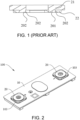
FIG. 1 is a schematic view of a structure of a cooperative connection manner of a copper layer and an aluminum layer in the prior art. -
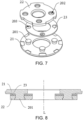
FIG. 2 is a schematic view of a structure of a cover plate assembly in an embodiment of the disclosure. -
FIG. 3 is a schematic view of an exploded structure of a cover plate assembly in an embodiment of the disclosure. -
FIG. 4 is a schematic view of a cross-sectional structure of an outer conductive member in an embodiment of the disclosure. -
FIG. 5 is a schematic top view of an outer conductive member in a cover plate assembly in an embodiment of the disclosure. -
FIG. 6 is a schematic view of an exploded structure of an outer conductive member in a cover plate assembly in an embodiment of the disclosure. -
FIG. 7 is a schematic view of another exploded structure of an outer conductive member in a cover plate assembly in an embodiment of the disclosure. -
FIG. 8 is a schematic view of a cross-sectional structure of an outer conductive member along A-A inFIG. 5 . - The following describes the implementation of the disclosure through specific examples. Persons skilled in the art can easily understand other advantages and effects of the disclosure from the content disclosed in the specification. The disclosure can also be implemented or applied through other different specific implementations. Various modifications or changes may also be made to the details in the specification based on different viewpoints and applications without departing from the spirit of the disclosure.
- It should be noted that the drawings provided in the embodiments only illustrate the basic concept of the disclosure in a schematic manner, and the drawings only show the assemblies related to the disclosure and are not drawn according to the number of assemblies, shapes, and sizes during actual implementation. During actual implementation, the type, number, and proportion of each assembly can be changed at will, and the layout type of the assembly may also be more complex.
- Please refer to
FIG. 1 to FIG. 8 . The disclosure provides a cover plate assembly, a battery cell, and a battery pack. The inventor knows a way to connect a battery cell to an external electrical connection member through an outer conductive member in the battery cell. The outer conductive member is generally made of a copper-aluminum composite plate or is formed by connecting a copper layer and an aluminum layer through adopting friction welding. However, the solution of adopting the composite plate has the issues of high raw material cost and complex process, and low material utilization during production. Adopting the friction welding has the issues of complex process, large machining volume, low material utilization, and extremely high cost. There is also the part composed of the copper plate and the aluminum plate. The copper plate and the aluminum plate are fixedly connected through riveting to form the outer conductive member, but in this way, a gap is likely to exist at a connection between the copper plate and the aluminum plate, which causes the connection to be unreliable. Please refer toFIG. 1 . In order to prevent the issue of the gap at the connection between the copper plate and the aluminum plate caused by riveting, in the prior art, brazing is added between the copper plate and the aluminum plate. However, during an actual production process, it is found that when too much solder is applied in the middle, the solder may easily overflow from sides of afirst metal layer 21 and asecond metal layer 22 and/or overflow from a gap between aprotrusion 201 and a firstfitting hole 202, thereby affecting other processes, and when too little is applied, there is still a gap between adjacent surfaces of copper and aluminum and/or between theprotrusion 201 and the firstfitting hole 202, such that the contact area is too small and the strength is difficult to be ensured. Also, the uniformity of the solder may easily cause a riveting post on the aluminum to slightly protrude, leading to the issue of poor high consistency. For example, when the solder on adjacent surfaces of thefirst metal layer 21 and thesecond metal layer 22 is unevenly distributed, the height of a surface of the outer conductive member relative to thecover plate body 10 is inconsistent. Therefore, in order to solve the above issues, the disclosure provides a cover plate assembly and a battery cell. Acover plate assembly 100 includes acover plate body 10, an outerconductive member 20, and an electrode lead-out member. Thecover plate body 10 is provided with a through hole, the outerconductive member 20 is disposed on a side of thecover plate body 10 away from an electrode assembly, and the electrode lead-out member passes through the through hole and is connected to the outerconductive member 20. - Please refer to
FIG. 2 to FIG. 8 . In the embodiment, the outerconductive member 20 includes afirst metal layer 21, asecond metal layer 22, and athird metal layer 23. Thefirst metal layer 21 includes a first metal, thesecond metal layer 22 includes a second metal, and thethird metal layer 23 includes a third metal. Thethird metal layer 23 is disposed between thefirst metal layer 21 and thesecond metal layer 22, and thethird metal layer 23 is respectively connected to thefirst metal layer 21 and thesecond metal layer 22 to form a first composite layer and a second composite layer, wherein the first composite layer includes the first metal and the third metal, and the second composite layer includes the second metal and the third metal. That is, in the disclosure, thethird metal layer 23 is disposed between thefirst metal layer 21 and thesecond metal layer 22, so that the composite layers are formed at the junctions between thethird metal layer 23 and thefirst metal layer 21 and thesecond metal layer 22, so that thefirst metal layer 21 and thesecond metal layer 22 are stably connected, and bonding surfaces thereof are larger to ensure the reliability and stability of the connection between thefirst metal layer 21 and thesecond metal layer 22. It should also be noted that thethird metal layer 23 is disposed between thefirst metal layer 21 and thesecond metal layer 22 to prevent the issue of the height inconsistency of the surface of the outer conductive member relative to thecover plate body 10 caused by uneven solder filled between thefirst metal layer 21 and thesecond metal layer 22. Furthermore, thefirst metal layer 21, thesecond metal layer 22, and thethird metal layer 23 are bonded together through hot pressing. During the hot pressing, surfaces of thefirst metal layer 21 and thesecond metal layer 22 are evenly stressed, thereby further ensuring the high consistency of the outerconductive member 20. - It should be noted that the outer
conductive member 20 is preferably a negative conductive member of the battery cell. - Please refer to
FIG. 2 andFIG. 4 toFIG. 8 . In the embodiment, thethird metal layer 23 is fixedly connected to thefirst metal layer 21 and thesecond metal layer 22 through hot pressing to form the first composite layer and the second composite layer, and the hot pressing thereof enables a stable connection between thefirst metal layer 21 and thesecond metal layer 22, the bonding surfaces are larger, and the hot pressing manner enables contact positions of thefirst metal layer 21 and thethird metal layer 21 to be partially fused together to form a metal composite section, thereby forming the composite layer. The contact positions of thesecond metal layer 22 and thethird metal layer 23 are partially fused to form a part of the metal composite section to improve the hot pressing effect and enable thethird metal layer 23 to fill the gap between thefirst metal layer 21 and thesecond metal layer 22, thereby ensuring the reliability and stability of the connection between thefirst metal layer 21 and thesecond metal layer 22. - It should be noted that at the junction between the
first metal layer 21 and thesecond metal layer 22, there are at least 3 main elements, which are respectively the main element of thefirst metal layer 21, the main element of thesecond metal layer 22, and the main element of thethird metal layer 23. The main element refers to the element with the highest content among 3 different metal layers. In the embodiment, thefirst metal layer 21 is an aluminum layer, thesecond metal layer 22 is a copper layer, and thethird metal layer 23 is at least one of nickel, silver, and tin, preferably nickel, so that thethird metal layer 23 can prevent thefirst metal layer 21 and thesecond metal layer 22 from being oxidized and corroded. - Please refer to
FIG. 2 andFIG. 4 toFIG. 8 . In the embodiment, the content of the first metal in the first composite layer increases in a direction away from thefirst metal layer 21 toward thefirst metal layer 21, that is, the content of the first metal increases along a direction from thesecond metal layer 22 toward thefirst metal layer 21 to enable a good transition between thefirst metal layer 21 and thethird metal layer 23, and ensure a reliable connection between thefirst metal layer 21 and thethird metal layer 23; and/or the content of the second metal in the second composite layer increases in a direction away from thesecond metal layer 22 toward thesecond metal layer 22, that is, the content of the second metal is increases along a direction from thefirst metal layer 21 toward thesecond metal layer 22 to enable a good transition between thesecond metal layer 22 and thethird metal layer 23, and ensure a reliable connection between thesecond metal layer 22 and thethird metal layer 23, thereby ensuring the stability of the overall structure of the outerconductive member 20. Further, the content of the second metal in the second composite layer is greater than the content of the first metal in the first composite layer to ensure a firm connection between the layers while ensuring that the outer conductive member has excellent conductive properties. - Please refer to
FIG. 2 andFIG. 4 toFIG. 8 . In the embodiment, the outerconductive member 20 may be made by first processing thefirst metal layer 21 and thesecond metal layer 22 into a single component, and then fixedly connecting thefirst metal layer 21, thesecond metal layer 22, and thethird metal layer 23 through hot pressing. Alternatively, thefirst metal layer 21, thesecond metal layer 22, and thethird metal layer 23 may be fixedly connected through hot pressing, and then processed to form the outerconductive member 20. That is, thefirst metal layer 21, thesecond metal layer 22, and thethird metal layer 23 may be separately processed and formed, and then connected to form the outerconductive member 20, or thefirst metal layer 21, thesecond metal layer 22, and thethird metal layer 23 may be connected and formed, and then processed to form the outerconductive member 20, which can reduce the difficulty of manufacturing, and each component may be separately processed and formed to prevent material waste, which can improve material utilization to reduce material cost. In the embodiment, the connection process between thefirst metal layer 21, thesecond metal layer 22, and thethird metal layer 23 may be to first fixedly connect thethird metal layer 23 to one of thefirst metal layer 21 and the second metal layers 22, and then fixedly connect to the other one. - Please refer to
FIG. 2 andFIG. 4 toFIG. 8 . In the embodiment, thethird metal layer 23 covers at least a part of a surface of thefirst metal layer 21 close to thesecond metal layer 22 or a part of a surface of thesecond metal layer 22 close to thefirst metal layer 21, that is, a partial region of the adjacent surface of thefirst metal layer 21 or thesecond metal layer 22 is covered with thethird metal layer 22, so that the region covered with thethird metal layer 23 forms the composite layer after hot pressing to ensure the reliable connection between thefirst metal layer 21 and thesecond metal layer 22 after hot pressing and fixing. Further, thethird metal layer 23 completely covers the surface with a larger area among the surface of thefirst metal layer 21 close to thesecond metal layer 22 and the surface of thesecond metal layer 22 close to thefirst metal layer 21 to ensure that thethird metal layer 23 can completely fill the gap between the two opposite surfaces of thefirst metal layer 21 and thesecond metal layer 22 after hot pressing and ensure that the connection area between thefirst metal layer 21 and thesecond metal layer 22 is large enough, thereby ensuring the conductive properties of the outerconductive member 20 and improving the reliability of the connection between thefirst metal layer 21 and thesecond metal layer 22. - Please refer to
FIG. 2 andFIG. 4 toFIG. 8 . In the embodiment, thethird metal layer 23 evenly covers the surface of thefirst metal layer 21 close to thesecond metal layer 22 or the surface of thesecond metal layer 22 close to thefirst metal layer 21. Through evenly covering the surface of thefirst metal layer 21 or thesecond metal layer 22 with thethird metal layer 23, affecting the hot pressing effect caused by uneven thickness of thethird metal layer 23 can be prevented, thereby improving the reliability of the connection between thefirst metal layer 21 and thesecond metal layer 22 while preventing the issue of the height inconsistency of the outerconductive member 20 caused by the uneven thickness of thethird metal layer 23 on the surface of thefirst metal layer 21 or the surface of thesecond metal layer 22 to improve the height consistency of the outerconductive member 20, thereby facilitating the connection of the outerconductive member 20 with other structures. For example, in the embodiment, thethird metal layer 23 evenly covers the surface of thefirst metal layer 21 to form an integrated structure with thefirst metal layer 21 or the surface of thesecond metal layer 22 to form an integrated structure with thesecond metal layer 22 through electroplating. Of course, in some other embodiments, thethird metal layer 23 may also evenly cover thefirst metal layer 21 or thesecond metal layer 22 through spraying. - Please refer to
FIG. 2 andFIG. 4 toFIG. 8 . In the embodiment, a surface of one of thefirst metal layer 21 and thesecond metal layer 22 close to the other one is provided with at least oneprotrusion 201, a surface of the other one close to the one is provided with a firstfitting hole 202 corresponding to the at least oneprotrusion 201, and thethird metal layer 23 is provided with a secondfitting hole 203 corresponding to theprotrusion 201. The at least oneprotrusion 201 is fittingly connected to the corresponding firstfitting hole 202 and secondfitting hole 203. For example, the surface of thefirst metal layer 21 close to thesecond metal layer 22 is provided withmultiple protrusions 201, and theprotrusions 201 are evenly spaced on thefirst metal layer 21 along a circumferential direction thereof. Correspondingly, thesecond metal layer 22 is provided with multiple firstfitting holes 202 fitted to theprotrusions 201, and thethird metal layer 23 is provided with the second fitting holes 203 fitted to theprotrusions 201. Theprotrusions 201 are fittingly connected to the corresponding firstfitting holes 202 and second fitting holes 203, which further improves the reliability and stability of the connection between thefirst metal layer 21 and thesecond metal layer 22 through the riveting of the protrusions and the fitting holes. During the hot pressing process, thethird metal layer 23 is respectively connected to thefirst metal layer 21 and thesecond metal layer 22 to form the first composite layer and the second composite layer. At the same time, theprotrusions 201 may be synchronously pressed into the firstfitting holes 202 and the second fitting holes 203 to implement the reliable connection between thefirst metal layer 21 and thesecond metal layer 22, that is, the two processes of hot pressing connection and riveting are implemented through one process, which reduces the difficulty of manufacturing to increase the production capacity and save cost. - Please refer to
FIG. 2 andFIG. 4 toFIG. 8 . In the embodiment, theprotrusions 201 are symmetrically distributed on one of thefirst metal layer 21 and thesecond metal layer 22 along a central axis L of the outerconductive member 20, the firstfitting holes 202 are symmetrically distributed on the other one of thefirst metal layer 21 and thesecond metal layer 22 along the central axis L of the outerconductive member 20, and the second fitting holes 203 are symmetrically distributed on thethird metal layer 23 along the central axis L of the outerconductive member 20. That is, theprotrusions 201, the first fitting holes 202, and the second fitting holes 203 are symmetrically distributed along the central axis L of the outerconductive member 20, so that when thefirst metal layer 21, thesecond metal layer 22, and thethird metal layer 23 are fittingly connected, theprotrusions 201 and the firstfitting holes 202 and the second fitting holes 203 are fittingly connected to facilitate riveting. At the same time, the symmetrical distribution along the central axis L enables thefirst metal layer 21, thesecond metal layer 22, and thethird metal layer 23 to be evenly stressed at each position when connected, thereby improving the stability and reliability of the connection between the metal layers. - Please refer to
FIG. 2 andFIG. 4 toFIG. 8 . In the embodiment, an outer surface of theprotrusion 201 or an inner surface of the firstfitting hole 202 is covered with thethird metal layer 23, that is, in addition to covering the two opposite surfaces of thefirst metal layer 21 and thesecond metal layer 22, thethird metal layer 23 also covers between theprotrusion 201 and the firstfitting hole 202, so that thethird metal layer 23 can fill a gap between theprotrusion 201 and the firstfitting hole 202 after hot pressing and riveting to improve the riveting effect to further ensure the reliable connection between thefirst metal layer 21 and thesecond metal layer 22. - Please refer to
FIG. 2 andFIG. 4 . In the embodiment, along a radial direction of the outerconductive member 20, in a direction away from the through hole toward the through hole, a part of the surface of thesecond metal layer 22 close to thefirst metal layer 21 that exceeds thefirst metal layer 21 is not covered with thethird metal layer 23, and the part not covered with thethird metal layer 23 is connected to the electrode lead-out member, for example, through welding. Since the part is not covered with thethird metal layer 23, the electrode lead-out member is directly welded to thesecond metal layer 22, thereby ensuring the stability and reliability of the welding between the electrode lead-out member and thesecond metal layer 22. - Please refer to
FIG. 2 andFIG. 4 toFIG. 8 . In the embodiment, the thickness of thethird metal layer 23 is set between 0.5 µm and 1000 µm. In practice, it is found that if the thickness is lower than 0.5 um, it will easily cause thethird metal layer 23 to be unable to completely fill the gap between thefirst metal layer 21 and thesecond metal layer 22 during hot pressing, which affects the reliability of the connection between thefirst metal layer 21 and thesecond metal layer 22, and if the thickness is higher than 1000 um, it will easily affect the hot pressing effect between thefirst metal layer 21, thesecond metal layer 22, and the third metal layer during hot pressing, which affects the reliability of the connection between thefirst metal layer 21 and thesecond metal layer 22, and there may be a thicker metal section between thefirst metal layer 21 and thesecond metal layer 22 after hot pressing, thereby easily affecting the overall conductive properties of the outerconductive member 20. Therefore, the thickness of thethird metal layer 23 is set between 0.5 µm and 1000 µm, so that thethird metal layer 23 can completely fill the gap between thefirst metal layer 21 and thesecond metal layer 22, and the hot pressing effect during hot pressing can also be ensured, thereby ensuring that the composite layer with sufficient thickness can be smoothly formed to ensure the reliability of the connection between thefirst metal layer 21 and thesecond metal layer 22, and also ensure the overall conductive properties of the outerconductive member 20. Furthermore, the thickness of thethird metal layer 23 is set between 5 µm and 10 µm. If the thickness is lower than 5 µm, it will easily cause the inability to form the composite layer with sufficient thickness during hot pressing to affect the reliability of the connection between thefirst metal layer 21 and thesecond metal layer 22, and if the thickness is higher than 10 um, it will easily affect the overall thickness of the outerconductive member 20, which causes the surface of the outerconductive member 20 to protrude too high relative to thecover plate body 10, thereby affecting the subsequent connection between the outerconductive member 20 and other structures, and the assembly of the battery cell. Therefore, the thickness of thethird metal layer 23 is set between 5 µm and 10 µm to ensure the formation of the composite layer with sufficient thickness, so that the connection between thefirst metal layer 21 and thesecond metal layer 22 is reliable, and the height of the outerconductive member 20 can also be prevented from being too high, thereby ensuring that the subsequent connection between the outerconductive member 20 and other structures, and the assembly of the battery cell can be smoothly performed. It should also be noted that in the embodiment, the thickness of the second composite layer is d, the total thickness of the first composite layer and the second composite layer is a, and the thickness of the second composite layer and the total thickness satisfy the relational expression 0.2a≤d≤0.9a, thereby ensuring the formation of the composite layer with sufficient thickness, so that thethird metal layer 22 is reliably connected between thefirst metal layer 21 and thesecond metal layer 22 after hot pressing. - Please refer to
FIG. 2 andFIG. 4 toFIG. 8 . In the embodiment, the outerconductive member 20 is, for example, obtained through the following process. First, thefirst metal layer 21 and thesecond metal layer 22 are respectively processed into the required shapes. According to requirements, thethird metal layer 23 is plated on the surface of thefirst metal layer 21 close to thesecond metal layer 22 or the surface of thesecond metal layer 22 close to thefirst metal layer 21 to facilitate the combination of the two. Thefirst metal layer 21 and thesecond metal layer 22 are fitted together. The fittedfirst metal layer 21 andsecond metal layer 22 are placed on a hot press for hot pressing. A briquette is raised to a certain temperature and then moved downward, so that the briquette contacts and extrudes the surfaces of thefirst metal layer 21 and thesecond metal layer 22. During the hot pressing process, thethird metal layer 23 respectively forms the composite layers withfirst metal layer 21 and thesecond metal layer 22, and theprotrusion 201 may be synchronously riveted into the firstfitting hole 202 to complete the processing of the outerconductive member 20. The two processes of hot pressing connection and riveting are implemented through one process, which reduces the difficulty of manufacturing to increase the production capacity and save cost. It should be noted that the briquette contacting thefirst metal layer 21 and thesecond metal layer 22 may be made of a material with high hardness or high thermal conductivity such as graphite, and the temperature of the briquette respectively corresponding to thefirst metal layer 21 and thesecond metal layer 22 should be lower than the melting point thereof, so that thethird metal layer 23 may be combined with thefirst metal layer 21 and thesecond metal layer 22 to form the composite layers. It should be noted that after thefirst metal layer 21 and thesecond metal layer 22 in the outerconductive member 20 are peeled off, a residual area of thethird metal layer 23 electroplated on one of thefirst metal layer 21 and thesecond metal layer 22 remaining on the other one of thefirst metal layer 21 and thesecond metal layer 22 is S1, the area of thethird metal layer 23 is S2, and the area S1 and the area S2 satisfy the relational expression 0.352≤S1≤S2. Further, the residual area S1 and the third metal layer area S2 satisfy the relational expression 0.652≤S1≤0.952. For example, before hot pressing, thethird metal layer 23 is electroplated on the surface of thesecond metal layer 22. After being peeled off, a part of thethird metal layer 23 is adhered onto thefirst metal layer 21. That is, after being peeled off, the residual area S1 of thethird metal layer 23 on thefirst metal layer 21 is set between 0.3 S2 and S2 to ensure that thethird metal layer 23 and thefirst metal layer 22 and thesecond metal layer 22 are firmly fused and connected together during hot pressing, thereby improving the reliability and stability of the connection between thefirst metal layer 21 and thesecond metal layer 22. - Please refer to
FIG. 2 to FIG. 8 . The disclosure also provides a battery cell, which includes thecover plate assembly 100 and a shell. An electrode assembly is installed in the shell. One end of an electrode lead-out member in thecover plate assembly 100 is connected to the electrode assembly, and the other end passes through a through hole and is electrically connected to thesecond metal layer 22 of thecover plate assembly 100. Thecover plate body 10 is provided with the through hole and is surrounded by agroove 102 and anouter support member 103. Theouter support member 103 is disposed around the outer periphery of the outerconductive member 20 and is installed in thegroove 102. Thecover plate assembly 100 is the same as or similar to the structure of thecover plate assembly 100 described in the above embodiment. In order to prevent repetition, there will not be reiteration here. - The disclosure provides a cover plate assembly, a battery cell, and a battery pack. Through setting a third metal layer between a first metal layer and a second metal layer, the third metal layer respectively forms a first composite layer including a first metal and a third metal with the first metal layer and forms a second composite layer including a second metal and the third metal with the second metal layer. That is, the metal composite layers are formed at the contact positions of the third metal layer and the first metal layer and the second metal layer to ensure the reliability and stability of the connection between the first metal layer and the second metal layer, and the third metal layer can fill the gap between the first metal layer and the second metal layer to further improve the reliability and stability of the connection between the first metal layer and the second metal layer.
- The above description is only preferred embodiments of the disclosure and an explanation of the technical principles used. Persons skilled in the art should understand that the scope involved in the disclosure is not limited to technical solutions formed by a specific combination of the above technical features, and should also cover other technical solutions formed by any combination of the above technical features or their equivalent features without departing from the concept of the disclosure, such as the technical solutions formed by replacing the above features with technical features having similar functions as disclosed in (but not limited to) the disclosure.
- Except for the technical features in the specification, the remaining technical features are known to persons skilled in the art. In order to highlight the inventive features of the disclosure, the remaining technical features will not be described in detail here.
-
- 100: cover plate assembly,
- 10: cover plate body,
- 20: outer conductive member,
- 102: groove,
- 103: outer support member,
- 21: first metal layer,
- 22: second metal layer,
- 23: third metal layer,
- 201: protrusion,
- 202: first fitting hole,
- 203: second fitting hole.
Claims (15)
- A cover plate assembly (100), comprising:a cover plate body (10), provided with a through hole;an outer conductive member (20), disposed on a side of the cover plate body (10) away from an electrode assembly, the outer conductive member (20) comprising a first metal layer (21), a second metal layer (22), and a third metal layer (23) disposed between the first metal layer (21) and the second metal layer (22), wherein the first metal layer (21) comprises a first metal, the second metal layer (22) comprises a second metal, and the third metal layer (23) comprises a third metal,wherein the third metal layer (23) is respectively connected to the first metal layer (21) and the second metal layer (22) to form a first composite layer and a second composite layer, the first composite layer comprises the first metal and the third metal, and the second composite layer comprises the second metal and the third metal;an electrode lead-out member, passing through the through hole and electrically connected to the outer conductive member (20).
- The cover plate assembly (100) according to claim 1, wherein a content of the first metal in the first composite layer increases in a direction away from the first metal layer (21) toward the first metal layer (21).
- The cover plate assembly (100) according to claim 1, wherein a content of the second metal in the second composite layer increases in a direction away from the second metal layer (22) toward the second metal layer (22).
- The cover plate assembly (100) according to claim 1, wherein a content of the second metal in the second composite layer is greater than a content of the first metal in the first composite layer.
- The cover plate assembly(100) according to claim 1, wherein the third metal layer (23) covers at least a part of a surface of the first metal layer (21) close to the second metal layer (22) or a part of a surface of the second metal layer (22) close to the first metal layer (21).
- The cover plate assembly (100) according to claim 5, wherein the third metal layer (23) completely covers one with a larger area of the surface of the first metal layer (21) close to the second metal layer (22) and the surface of the second metal layer (22) close to the first metal layer (21), and the third metal layer (23) evenly covers the surface of the first metal layer (21) close to the second metal layer (22) or the surface of the second metal layer (22) close to the first metal layer (21).
- The cover plate assembly (100) according to claim 1, wherein a surface of one of the first metal layer (21) and the second metal layer (22) close to other one of the first metal layer (21) and the second metal layer (22) is provided with at least one protrusion (201), a surface of the other one of the first metal layer (21) and the second metal layer (22) close to the one of the first metal layer (21) and the second metal layer (22) is provided with a first fitting hole (202) corresponding to the at least one protrusion (201), the third metal layer (23) is provided with a second fitting hole (203) corresponding to the at least one protrusion (201), and the at least one protrusion (201) is fittingly connected to the corresponding first fitting hole (202) and second fitting hole (203).
- The cover plate assembly (100) according to claim 7, wherein a surface of the first metal layer (21) close to the second metal layer (22) is provided with the at least one protrusion (201), a surface of the second metal layer (22) close to the first metal layer (21) is provided with the first fitting hole (202) fitted to the at least one protrusion (201), the third metal layer (23) is provided with the second fitting hole (203) fitted to the at least one protrusion (201), and the at least one protrusion (201) is fittingly connected to the corresponding first fitting hole (202) and second fitting hole (203).
- The cover plate assembly (100) according to claim 7, wherein the at least one protrusion (201) is symmetrically distributed on one of the first metal layer (21) and the second metal layer (22) along a central axis of the outer conductive member (20), the first fitting holes (202) are symmetrically distributed on other one of the first metal layer (21) and the second metal layer (22) along the central axis of the outer conductive member (20), and the second fitting holes (203) are symmetrically distributed on the third metal layer (23) along the central axis of the outer conductive member (20).
- The cover plate assembly (100) according to claim 7, wherein an outer surface of the at least one protrusion (201) or an inner surface of the first fitting hole (202) is covered with the third metal layer (23).
- The cover plate assembly (100) according to claim 1, wherein along a radial direction of the outer conductive member (20), in a direction away from the through hole toward the through hole, a part of a surface of the second metal layer (22) close to the first metal layer (21) that exceeds the first metal layer (21) is not covered with the third metal layer (23), and a thickness of the third metal layer (23) is set between 0.5 µm and 1000 µm.
- The cover plate assembly (100) according to claim 11, wherein the thickness of the third metal layer (23) is set between 5 µm and 10 µm.
- The cover plate assembly (100) according to claim 1, wherein a thickness of the second composite layer is d, a total thickness of the first composite layer and the second composite layer is a, and a relational expression 0.2a≤d≤0.9a is satisfied, and the third metal layer (23) comprises at least one of nickel, silver, and tin.
- A battery cell, comprising: the cover plate assembly (100) according to any one of claims 1 to 13, anda shell, installed with the electrode assembly,wherein an end of the electrode lead-out member in the cover plate assembly (100) is connected to the electrode assembly, and other end passes through the through hole and is electrically connected to the second metal layer (22) in the cover plate assembly (100).
- A battery pack, comprising the battery cell according to claim 14.
Applications Claiming Priority (1)
| Application Number | Priority Date | Filing Date | Title |
|---|---|---|---|
| CN202323260371.7U CN221304936U (en) | 2023-11-30 | 2023-11-30 | Cover plate assembly and battery cell |
Publications (1)
| Publication Number | Publication Date |
|---|---|
| EP4564545A1 true EP4564545A1 (en) | 2025-06-04 |
Family
ID=89386059
Family Applications (1)
| Application Number | Title | Priority Date | Filing Date |
|---|---|---|---|
| EP23218039.8A Pending EP4564545A1 (en) | 2023-11-30 | 2023-12-19 | Cover plate assembly, battery cell, and battery pack |
Country Status (4)
| Country | Link |
|---|---|
| US (1) | US20250183428A1 (en) |
| EP (1) | EP4564545A1 (en) |
| JP (1) | JP2025088672A (en) |
| CN (1) | CN221304936U (en) |
Citations (4)
| Publication number | Priority date | Publication date | Assignee | Title |
|---|---|---|---|---|
| JPH11298143A (en) * | 1998-04-10 | 1999-10-29 | Mitsubishi Gas Chem Co Inc | Manufacturing method of multilayer printed wiring board |
| US20140011074A1 (en) * | 2011-03-30 | 2014-01-09 | Hitachi Metals, Ltd. | Negative electrode terminal and cover member for lithium ion battery, and lithium ion battery |
| JP2015116577A (en) * | 2013-12-17 | 2015-06-25 | 三菱電機株式会社 | Bonding method of clad metal with metal component, and method for manufacturing thermal tripping device with use of the bonding method, and circuit breaker |
| US9525228B2 (en) * | 2013-09-25 | 2016-12-20 | Hitachi Metals, Ltd. | Battery terminal, method for manufacturing battery terminal, and battery |
Family Cites Families (5)
| Publication number | Priority date | Publication date | Assignee | Title |
|---|---|---|---|---|
| WO2012169055A1 (en) * | 2011-06-10 | 2012-12-13 | 日立ビークルエナジー株式会社 | Secondary battery |
| JP6070490B2 (en) * | 2013-09-11 | 2017-02-01 | 日立金属株式会社 | Battery terminal and battery terminal manufacturing method |
| JP6398602B2 (en) * | 2014-10-22 | 2018-10-03 | 株式会社Gsユアサ | Power storage element, method for manufacturing the same, and power storage device |
| EP3461579B1 (en) * | 2017-03-24 | 2021-10-13 | Hitachi Metals, Ltd. | Method for producing cladding material |
| WO2020144904A1 (en) * | 2019-01-09 | 2020-07-16 | ビークルエナジージャパン株式会社 | Dissimilar metal joined body, negative electrode external terminal for secondary batteries using same, and secondary battery |
-
2023
- 2023-11-30 CN CN202323260371.7U patent/CN221304936U/en active Active
- 2023-12-12 US US18/537,625 patent/US20250183428A1/en active Pending
- 2023-12-19 EP EP23218039.8A patent/EP4564545A1/en active Pending
- 2023-12-20 JP JP2023215112A patent/JP2025088672A/en active Pending
Patent Citations (4)
| Publication number | Priority date | Publication date | Assignee | Title |
|---|---|---|---|---|
| JPH11298143A (en) * | 1998-04-10 | 1999-10-29 | Mitsubishi Gas Chem Co Inc | Manufacturing method of multilayer printed wiring board |
| US20140011074A1 (en) * | 2011-03-30 | 2014-01-09 | Hitachi Metals, Ltd. | Negative electrode terminal and cover member for lithium ion battery, and lithium ion battery |
| US9525228B2 (en) * | 2013-09-25 | 2016-12-20 | Hitachi Metals, Ltd. | Battery terminal, method for manufacturing battery terminal, and battery |
| JP2015116577A (en) * | 2013-12-17 | 2015-06-25 | 三菱電機株式会社 | Bonding method of clad metal with metal component, and method for manufacturing thermal tripping device with use of the bonding method, and circuit breaker |
Also Published As
| Publication number | Publication date |
|---|---|
| US20250183428A1 (en) | 2025-06-05 |
| JP2025088672A (en) | 2025-06-11 |
| CN221304936U (en) | 2024-07-09 |
Similar Documents
| Publication | Publication Date | Title |
|---|---|---|
| US8785029B2 (en) | Connection plate for battery terminals and method for manufacturing connection plate for battery terminals | |
| US20120267152A1 (en) | Substrate and method of manufacturing substrate | |
| CN113224427A (en) | PCB type battery cover plate, preparation method thereof and battery with PCB type battery cover plate | |
| EP4564545A1 (en) | Cover plate assembly, battery cell, and battery pack | |
| CN213989128U (en) | Novel utmost point post subassembly, top cap structure and power battery | |
| CN218334025U (en) | Lithium battery top cover assembly | |
| CN218783129U (en) | Top Cover Structure and Battery | |
| CN222673159U (en) | A battery riveted cover structure, battery cell and battery pack | |
| CN211387330U (en) | Spot-bottom welding needle structure of cylindrical battery | |
| CN220021341U (en) | Cover assembly and battery containing same | |
| CN219498118U (en) | Sodium ion battery pole piece assembly and sodium ion battery | |
| CN201657502U (en) | Printed circuit board | |
| CN211700343U (en) | PCB type battery cover plate and battery with same | |
| US20260074388A1 (en) | Conductive structure, cover plate assembly, and battery cell | |
| CN211670329U (en) | FPC-aluminum sheet connecting structure integrating crimping and welding and connector | |
| CN220934344U (en) | Pole assembly and cell cover | |
| CN106785354A (en) | A kind of antenna contact chip and its production method, mobile terminal | |
| CN206040793U (en) | Compound area of copper nickel that high magnification battery used | |
| CN222813736U (en) | Laser welding cover plate structure and battery | |
| CN222867993U (en) | A negative electrode current collecting plate and cylindrical lithium battery | |
| CN219917353U (en) | Cover plate assembly and square secondary battery | |
| CN221668943U (en) | Cover plate assembly and battery containing the same | |
| CN219498112U (en) | Tab and battery core | |
| CN223713013U (en) | Electrode structure | |
| CN221327911U (en) | Top cap and contain its battery |
Legal Events
| Date | Code | Title | Description |
|---|---|---|---|
| PUAI | Public reference made under article 153(3) epc to a published international application that has entered the european phase |
Free format text: ORIGINAL CODE: 0009012 |
|
| STAA | Information on the status of an ep patent application or granted ep patent |
Free format text: STATUS: REQUEST FOR EXAMINATION WAS MADE |
|
| 17P | Request for examination filed |
Effective date: 20231219 |
|
| AK | Designated contracting states |
Kind code of ref document: A1 Designated state(s): AL AT BE BG CH CY CZ DE DK EE ES FI FR GB GR HR HU IE IS IT LI LT LU LV MC ME MK MT NL NO PL PT RO RS SE SI SK SM TR |