EP4564454A2 - Anodenaktivmaterial für lithiumsekundärbatterie und lithiumsekundärbatterie damit - Google Patents
Anodenaktivmaterial für lithiumsekundärbatterie und lithiumsekundärbatterie damit Download PDFInfo
- Publication number
- EP4564454A2 EP4564454A2 EP24216684.1A EP24216684A EP4564454A2 EP 4564454 A2 EP4564454 A2 EP 4564454A2 EP 24216684 A EP24216684 A EP 24216684A EP 4564454 A2 EP4564454 A2 EP 4564454A2
- Authority
- EP
- European Patent Office
- Prior art keywords
- active material
- secondary battery
- carbon
- lithium secondary
- anode active
- Prior art date
- Legal status (The legal status is an assumption and is not a legal conclusion. Google has not performed a legal analysis and makes no representation as to the accuracy of the status listed.)
- Pending
Links
Images

Classifications
-
- H—ELECTRICITY
- H01—ELECTRIC ELEMENTS
- H01M—PROCESSES OR MEANS, e.g. BATTERIES, FOR THE DIRECT CONVERSION OF CHEMICAL ENERGY INTO ELECTRICAL ENERGY
- H01M4/00—Electrodes
- H01M4/02—Electrodes composed of, or comprising, active material
- H01M4/13—Electrodes for accumulators with non-aqueous electrolyte, e.g. for lithium-accumulators; Processes of manufacture thereof
- H01M4/133—Electrodes based on carbonaceous material, e.g. graphite-intercalation compounds or CFx
-
- H—ELECTRICITY
- H01—ELECTRIC ELEMENTS
- H01M—PROCESSES OR MEANS, e.g. BATTERIES, FOR THE DIRECT CONVERSION OF CHEMICAL ENERGY INTO ELECTRICAL ENERGY
- H01M4/00—Electrodes
- H01M4/02—Electrodes composed of, or comprising, active material
- H01M4/36—Selection of substances as active materials, active masses, active liquids
- H01M4/362—Composites
- H01M4/366—Composites as layered products
-
- C—CHEMISTRY; METALLURGY
- C01—INORGANIC CHEMISTRY
- C01B—NON-METALLIC ELEMENTS; COMPOUNDS THEREOF; METALLOIDS OR COMPOUNDS THEREOF NOT COVERED BY SUBCLASS C01C
- C01B32/00—Carbon; Compounds thereof
- C01B32/05—Preparation or purification of carbon not covered by groups C01B32/15, C01B32/20, C01B32/25, C01B32/30
-
- H—ELECTRICITY
- H01—ELECTRIC ELEMENTS
- H01M—PROCESSES OR MEANS, e.g. BATTERIES, FOR THE DIRECT CONVERSION OF CHEMICAL ENERGY INTO ELECTRICAL ENERGY
- H01M10/00—Secondary cells; Manufacture thereof
- H01M10/05—Accumulators with non-aqueous electrolyte
- H01M10/052—Li-accumulators
-
- H—ELECTRICITY
- H01—ELECTRIC ELEMENTS
- H01M—PROCESSES OR MEANS, e.g. BATTERIES, FOR THE DIRECT CONVERSION OF CHEMICAL ENERGY INTO ELECTRICAL ENERGY
- H01M4/00—Electrodes
- H01M4/02—Electrodes composed of, or comprising, active material
- H01M4/36—Selection of substances as active materials, active masses, active liquids
- H01M4/362—Composites
- H01M4/364—Composites as mixtures
-
- H—ELECTRICITY
- H01—ELECTRIC ELEMENTS
- H01M—PROCESSES OR MEANS, e.g. BATTERIES, FOR THE DIRECT CONVERSION OF CHEMICAL ENERGY INTO ELECTRICAL ENERGY
- H01M4/00—Electrodes
- H01M4/02—Electrodes composed of, or comprising, active material
- H01M4/36—Selection of substances as active materials, active masses, active liquids
- H01M4/38—Selection of substances as active materials, active masses, active liquids of elements or alloys
- H01M4/386—Silicon or alloys based on silicon
-
- H—ELECTRICITY
- H01—ELECTRIC ELEMENTS
- H01M—PROCESSES OR MEANS, e.g. BATTERIES, FOR THE DIRECT CONVERSION OF CHEMICAL ENERGY INTO ELECTRICAL ENERGY
- H01M4/00—Electrodes
- H01M4/02—Electrodes composed of, or comprising, active material
- H01M4/36—Selection of substances as active materials, active masses, active liquids
- H01M4/58—Selection of substances as active materials, active masses, active liquids of inorganic compounds other than oxides or hydroxides, e.g. sulfides, selenides, tellurides, halogenides or LiCoFy; of polyanionic structures, e.g. phosphates, silicates or borates
- H01M4/583—Carbonaceous material, e.g. graphite-intercalation compounds or CFx
- H01M4/587—Carbonaceous material, e.g. graphite-intercalation compounds or CFx for inserting or intercalating light metals
-
- H—ELECTRICITY
- H01—ELECTRIC ELEMENTS
- H01M—PROCESSES OR MEANS, e.g. BATTERIES, FOR THE DIRECT CONVERSION OF CHEMICAL ENERGY INTO ELECTRICAL ENERGY
- H01M4/00—Electrodes
- H01M4/02—Electrodes composed of, or comprising, active material
- H01M4/62—Selection of inactive substances as ingredients for active masses, e.g. binders, fillers
- H01M4/621—Binders
- H01M4/622—Binders being polymers
- H01M4/623—Binders being polymers fluorinated polymers
-
- H—ELECTRICITY
- H01—ELECTRIC ELEMENTS
- H01M—PROCESSES OR MEANS, e.g. BATTERIES, FOR THE DIRECT CONVERSION OF CHEMICAL ENERGY INTO ELECTRICAL ENERGY
- H01M4/00—Electrodes
- H01M4/02—Electrodes composed of, or comprising, active material
- H01M4/62—Selection of inactive substances as ingredients for active masses, e.g. binders, fillers
- H01M4/624—Electric conductive fillers
- H01M4/625—Carbon or graphite
-
- H—ELECTRICITY
- H01—ELECTRIC ELEMENTS
- H01M—PROCESSES OR MEANS, e.g. BATTERIES, FOR THE DIRECT CONVERSION OF CHEMICAL ENERGY INTO ELECTRICAL ENERGY
- H01M4/00—Electrodes
- H01M4/02—Electrodes composed of, or comprising, active material
- H01M4/62—Selection of inactive substances as ingredients for active masses, e.g. binders, fillers
- H01M4/628—Inhibitors, e.g. gassing inhibitors, corrosion inhibitors
-
- C—CHEMISTRY; METALLURGY
- C01—INORGANIC CHEMISTRY
- C01P—INDEXING SCHEME RELATING TO STRUCTURAL AND PHYSICAL ASPECTS OF SOLID INORGANIC COMPOUNDS
- C01P2002/00—Crystal-structural characteristics
- C01P2002/70—Crystal-structural characteristics defined by measured X-ray, neutron or electron diffraction data
- C01P2002/74—Crystal-structural characteristics defined by measured X-ray, neutron or electron diffraction data by peak-intensities or a ratio thereof only
-
- C—CHEMISTRY; METALLURGY
- C01—INORGANIC CHEMISTRY
- C01P—INDEXING SCHEME RELATING TO STRUCTURAL AND PHYSICAL ASPECTS OF SOLID INORGANIC COMPOUNDS
- C01P2004/00—Particle morphology
- C01P2004/80—Particles consisting of a mixture of two or more inorganic phases
-
- C—CHEMISTRY; METALLURGY
- C01—INORGANIC CHEMISTRY
- C01P—INDEXING SCHEME RELATING TO STRUCTURAL AND PHYSICAL ASPECTS OF SOLID INORGANIC COMPOUNDS
- C01P2006/00—Physical properties of inorganic compounds
- C01P2006/14—Pore volume
-
- C—CHEMISTRY; METALLURGY
- C01—INORGANIC CHEMISTRY
- C01P—INDEXING SCHEME RELATING TO STRUCTURAL AND PHYSICAL ASPECTS OF SOLID INORGANIC COMPOUNDS
- C01P2006/00—Physical properties of inorganic compounds
- C01P2006/16—Pore diameter
-
- C—CHEMISTRY; METALLURGY
- C01—INORGANIC CHEMISTRY
- C01P—INDEXING SCHEME RELATING TO STRUCTURAL AND PHYSICAL ASPECTS OF SOLID INORGANIC COMPOUNDS
- C01P2006/00—Physical properties of inorganic compounds
- C01P2006/40—Electric properties
-
- H—ELECTRICITY
- H01—ELECTRIC ELEMENTS
- H01M—PROCESSES OR MEANS, e.g. BATTERIES, FOR THE DIRECT CONVERSION OF CHEMICAL ENERGY INTO ELECTRICAL ENERGY
- H01M4/00—Electrodes
- H01M4/02—Electrodes composed of, or comprising, active material
- H01M2004/021—Physical characteristics, e.g. porosity, surface area
-
- H—ELECTRICITY
- H01—ELECTRIC ELEMENTS
- H01M—PROCESSES OR MEANS, e.g. BATTERIES, FOR THE DIRECT CONVERSION OF CHEMICAL ENERGY INTO ELECTRICAL ENERGY
- H01M4/00—Electrodes
- H01M4/02—Electrodes composed of, or comprising, active material
- H01M2004/026—Electrodes composed of, or comprising, active material characterised by the polarity
- H01M2004/027—Negative electrodes
-
- Y—GENERAL TAGGING OF NEW TECHNOLOGICAL DEVELOPMENTS; GENERAL TAGGING OF CROSS-SECTIONAL TECHNOLOGIES SPANNING OVER SEVERAL SECTIONS OF THE IPC; TECHNICAL SUBJECTS COVERED BY FORMER USPC CROSS-REFERENCE ART COLLECTIONS [XRACs] AND DIGESTS
- Y02—TECHNOLOGIES OR APPLICATIONS FOR MITIGATION OR ADAPTATION AGAINST CLIMATE CHANGE
- Y02E—REDUCTION OF GREENHOUSE GAS [GHG] EMISSIONS, RELATED TO ENERGY GENERATION, TRANSMISSION OR DISTRIBUTION
- Y02E60/00—Enabling technologies; Technologies with a potential or indirect contribution to GHG emissions mitigation
- Y02E60/10—Energy storage using batteries
Definitions
- the disclosure of this patent application relates to an anode active material for a lithium secondary battery and a lithium secondary battery including the same.
- a secondary battery which can be charged and discharged repeatedly has been widely employed as a power source of a mobile electronic device such as a camcorder, a mobile phone, a laptop computer, etc., according to developments of information and display technologies. Recently, a battery pack including the secondary battery is being developed and applied as a power source of an eco-friendly vehicle such as an electric automobile.
- the secondary battery examples include a lithium secondary battery, a nickelcadmium battery, a nickel-hydrogen battery, etc.
- the lithium secondary battery among the secondary batteries is being actively developed due to high operational voltage and energy density per unit weight, a high charging rate, a compact dimension, etc.
- the lithium secondary battery having higher capacity and power is being developed.
- silicon having high capacity can be combined with carbon to be used as an anode active material.
- a silicon-carbon composite anode active material has an increased volume expansion difference to result in cracks and an exposure to an electrolyte solution of the anode active material.
- anode active material for a lithium secondary battery having improved life-span properties.
- a lithium secondary battery having improved life-span properties.
- An anode active material for a lithium secondary battery includes a composite particle.
- the composite particle includes a carbon-based particle including pores, and a silicon-containing coating formed on a surface of the carbon-based particle.
- Equation 1 p1 is a central peak value of a peak having a maximum height in a range from 3.4 ⁇ to 4.1 ⁇ of a pair distribution function (PDF) spectrum obtained by a PDF analysis for the composite particle, and p2 is a central peak value of a peak having a maximum height in a range of 4.1 ⁇ to 4.9 ⁇ of the PDF spectrum obtained by the PDF analysis for the composite particle.
- PDF pair distribution function
- the peak distance may be in a range from 0.56 ⁇ to 0.59 ⁇ .
- the peak distance may be in a range from 0.57 ⁇ to 0.59 ⁇ .
- Ip1 is a maximum height of a peak in a range of 3.4 ⁇ to 4.1 ⁇ of the PDF spectrum obtained by the PDF analysis of the composite particle
- Ip2 is a maximum height of a peak in a range of 4.1 ⁇ to 4.9 ⁇ of the PDF spectrum obtained by the PDF analysis of the composite particle.
- the peak intensity ratio may be in a range from 0.13 to 0.29.
- the peak intensity ratio may be in a range from 0.15 to 0.28.
- a pore size of the carbon-based particle may be in a range from 0.1 nm to 10 nm.
- the pore size of the carbon-based particle may be in a range from 1 nm to 5 nm.
- the composite particle may further include a carbon coating formed on the silicon-containing coating.
- the carbon coating may include an amorphous carbon and/or a conductive polymer.
- the pores of the carbon-based particle may have a shape indented from an outermost portion of the carbon-based particle into an inside of the carbon-based particle.
- a lithium secondary battery includes an anode including the above-described anode active material for a lithium secondary battery, and a cathode facing the anode.
- physical and chemical stability of a composite particle may be improved.
- a capacity retention of a secondary battery may be improved.
- life-span properties of a secondary battery may be improved.
- the anode active material and the lithium secondary battery according to the present disclosure may be widely applied in green technology fields such as an electric vehicle, a battery charging station, a solar power generation, a wind power generation, etc., using a battery, etc.
- the anode active material and the lithium secondary battery according to the present disclosure may be used for eco-friendly electric vehicles and hybrid vehicles to prevent a climate change by suppressing air pollution and greenhouse gas emissions. etc.
- an anode active material for a lithium secondary battery (hereinafter, that may be abbreviated as an anode active material) including a composite particle. According to embodiments of the present disclosure, a lithium secondary battery including the anode active material is also provided.
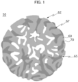
- FIG. 1 is a schematic cross-sectional view illustrating a composite particle in accordance with example embodiments.
- FIG. 1 illustrates a schematic shape of the composite particles for convenience of descriptions, but the structure/shape of the composite particle of the present disclosure is not limited to that illustrated in FIG. 1 .
- a cross-section of a carbon-based particle may be randomly changed from a circular shape.
- a silicon-containing coating may be partially formed on pores and a surface of the carbon-based particle, or may be formed as a plurality of discontinuous islands or patterns.
- a composite particle 50 includes a carbon-based particle 60 and a silicon (Si)-containing coating 70.
- the carbon-based particle 60 may include a pore 65.
- the carbon-based particles 60 are porous particles including a plurality of pores.
- the carbon-based particle 60 may include an activated carbon, a carbon nanotube, a carbon nanowire, graphene, a carbon fiber, carbon black, graphite, a porous carbon, a pyrolyzed cryogel, a pyrolyzed xerogel, a pyrolyzed aerogel, etc. These may be used alone or in a combination of two or more therefrom.
- the carbon-based particle 60 may include an amorphous structure or a crystalline structure.
- the carbon-based particle 60 may include the amorphous structure.
- durability of the anode active material may be increased, so that cracks may be suppressed during charging and discharging or an external impact. Accordingly, the life-span properties of the secondary battery may be improved.
- the silicon-containing coating 70 may be formed on a surface of the carbon-based particle 60 including the pores 65.
- volume expansion of silicon contained in the silicon-containing coating 70 may be alleviated by the pores 65. Accordingly, cracks due to a difference between volume expansion ratios of carbon (e.g., about 150 volume% or less) and silicon (e.g., about 400 volume% or more) during charging and discharging of the battery may be prevented while employing the relatively high capacity properties of silicon. Accordingly, gas generation due to a side reaction between the anode active material and an electrolyte solution may be prevented, and the life-span properties of the secondary battery may be improved.
- the pores 65 of the carbon-based particle 60 may have a shape indented into the carbon-based particle 60 from an outermost portion of the carbon-based particle 60 to an inside of the carbon-based particle 60.
- the pores 65 may include open pores to an outside of the carbon-based particles 60.
- a surface of the carbon-based particle and/or “a surface of the carbon-based particle 60” may refer to an outer surface 62 of the carbon-based particle 60, an inner surface 67 of the pore 65, or the outer surface 62 of the carbon-based particle 60 and the inner surface 67 of the pore 65.
- the silicon-containing coating 70 may be formed on at least a portion of the outer surface 62 of the carbon-based particle 60.
- the silicon-containing coating 70 may be formed on at least a portion of the inner surface 67 of the pore 65 of the carbon-based particles 60.
- the silicon-containing coating 70 may be formed on at least a portion of the outer surface 62 of carbon-based particle 60 and at least a portion of the inner surface 67 of pore 65.
- the silicon-containing coating 70 may include an amorphous silicon. Accordingly, stability of the composite particle may be improved and the life-span properties of the secondary battery may be improved.
- the silicon-containing coating 70 may not include a crystalline silicon. Accordingly, stability of the composite particle may be further improved and the life-span properties of the secondary battery may be further improved.
- a peak distance measured by a pair distribution function (PDF) analysis of the composite particle 50 and defined by Equation 1 below is 0.6 ⁇ or less, and, in some embodiments, may be in a range from 0.56 ⁇ to 0.59 ⁇ or from 0.57 ⁇ to 0.59 ⁇ .
- peak distance A ⁇ p2 ⁇ p1
- Equation 1 p1 is a central peak value of a peak having a maximum height in a range from 3.4 ⁇ to 4.1 ⁇ of a PDF spectrum obtained by the PDF analysis for the composite particle 50, and p2 is a central peak value of a peak having a maximum height in a range of 4.1 ⁇ to 4.9 ⁇ of the PDF spectrum obtained by the PDF analysis for the composite particle 50.
- the particle peak distance may correspond to a distance between silicon atoms included in the silicon-containing coating 70.
- the distance between the silicon atoms included in the silicon-containing coating 70 may be maintained at an appropriate level, so that stability and amorphousness of silicon may be enhanced. Accordingly, physical and chemical stability of the composite particle 50 may be improved, and the capacity retention during charging and discharging of the secondary battery may be improved.
- Scattering data for the PDF analysis may be collected, e.g., from a beamline 1C of Pohang Light Source (PLS-II) of Pohang Accelerator Research Institute (PAL).
- PLS-II Pohang Light Source
- PAL Pohang Accelerator Research Institute
- another equipment capable of measuring the scattering data may also be used.
- a sample of the composite particles 50 may be introduced into a capillary, and the scattering data including 2D scattering images was measured at a step size of 0.017 degree in a range of 5 to 80 degrees (2 ⁇ ) using a high energy X-ray (22.003 KeV) with a wavelength ( ⁇ ) of 0.56356 ⁇ .
- 1D scattering intensity data may be obtained by integrating the 2D scattering image using a software (e.g., Dioptas).
- a software e.g., Dioptas
- a diffraction peak of the current collector may be planarized.
- an X-ray scattered by the hollow capillary can be collected to obtain background data.
- the 1D scattering intensity data, the background data, the used wavelength and chemical composition may be applied to a software (e.g., PDFgetX3) to obtain a structural function S(Q).
- a relative intensity (background scale) of the background data relative to the 1D scattering intensity data may be set to 1.0, and a range of Q may be set to 0.1 to 12.0.
- a G(r) function may be obtained by a Fourier transforming of S(Q).
- the PDF spectrum may be obtained by illustrating a change in G(r) according to an interatomic distance (r).
- Equation 1 may be measured by drawing a baseline parallel to a horizontal axis (r) based on a vertical axis G(r) height when r of the PDF spectrum is 0 ⁇ , and then deriving a central peak value of a peak having a maximum height based on the baseline.
- a peak intensity ratio measured by the PDF analysis of the composite particle 50 and defined by Equation 2 below may be in a range from 0.1 to 0.35, and in an embodiment, may be in a range from 0.13 to 0.29, or from 0.15 to 0.28.
- peak intensity ration Ip2 / Ip1
- Ip1 is a maximum height of a peak in a range from 3.4 ⁇ to 4.1 ⁇ of the PDF spectrum obtained by the PDF analysis for the composite particle 50
- Ip2 is a maximum height of a peak in a range from 4.1 ⁇ to 4.9 ⁇ of the PDF spectrum obtained by the PDF analysis for the composite particle 50.
- the peak intensity ratio may correspond to a degree of dispersion of the PDF spectrum peak of silicon atoms included in the silicon-containing coating 70.
- the silicon atoms may each have an appropriate amorphousness and may be uniformly coated on the surface of the carbon-based particle 60. Accordingly, the life-span properties of the secondary battery may be improved.
- a size of the pore 65 of the carbon-based particle 60 may be in a range from 0.1 nm to 10 nm, from 0.5 nm to 8 nm, or from 1 nm to 5 nm. In the above range, excessive deposition of silicon may be prevented, and cracks of the anode active material during charging and discharging of the secondary battery may be further suppressed.
- the size of the pore 65 may refer to a diameter of an entrance of the pore 65 formed on the surface of the carbon-based particle 60.
- the silicon-containing coating 70 may include silicon, and optionally may further include SiOx (0 ⁇ x ⁇ 2).
- the composite particle 50 may not include silicon carbide (SiC). In this case, the capacity and life-span properties of the anode active material may be enhanced.
- the composite particle 50 may further include a carbon coating (not illustrated) formed on the silicon-containing coating 70. Accordingly, a contact between silicon and water in the anode active material may be prevented. Accordingly, a decrease in a discharge capacity and a capacity efficiency of the secondary battery may be prevented in a period from preparation of the anode active material and before formation of the anode.
- the carbon coating may be formed on a portion of the surface of the carbon-based particle 60 where the silicon-containing coating 70 is not formed.
- the carbon coating may entirely cover the carbon-based particle 60 and the silicon-containing coating 70. Accordingly, mechanical and chemical stability of the anode active material may be improved.
- the carbon coating may include at least one of carbon and a conductive polymer.
- the carbon may include an amorphous carbon.
- the conductive polymer may include polyacetylene, polyaniline, polypyrrole, polythiophene, etc.
- the carbon particle 60 including the pores 65 may be prepared.
- preliminary carbon particles and an additive may be mixed, and then a first firing and washing may be performed to form the carbon particles 60.
- the preliminary carbon particles may include at least one selected from the group consisting of glucose, sucrose, cellulose, a petroleum pitch, a coal pitch, a biomass and a resol oligomer.
- the additive may serve as a chemical etchant or a hard template.
- the chemical etchant may include a basic and/or acidic agent such as potassium hydroxide (KOH), potassium acetate, potassium carbonate (K 2 CO 3 ), sodium hydroxide (NaOH), sodium carbonate (Na 2 CO 3 ), ammonia water (NH 4 OH), sulfuric acid (H 2 SO 4 ).
- KOH potassium hydroxide
- K 2 CO 3 potassium carbonate
- NaOH sodium hydroxide
- Na 2 CO 3 sodium carbonate
- NH 4 OH ammonia water
- sulfuric acid H 2 SO 4
- the hard template may include silica, polystyrene, etc. These can be used alone or in a combination of two or more therefrom.
- the hard template may serve as, e.g., an additive for forming pores.
- the size of the pores 65 may be controlled according to a particle size of the hard template.
- the first firing may be performed at a temperature in a range from 600 °C to 900 °C. In this range, the size and/or volume of the pores 65 may be appropriately controlled.
- the washing may be performed by adding an acidic solution or an alkaline solution to the mixture.
- the acidic solution may include a hydrochloric acid (HCl) solution, a sulfuric acid (H 2 SO 4 ) solution, etc.
- the alkaline solution may include a NaOH solution, etc.
- the carbon-based particle 60 and a silicon-containing gas may be co-fired (e.g., a second firing) to form the composite particles 50 including the silicon-containing coating 70 formed on the surface of the carbon-based particles 60.
- the silicon-containing gas may include a silane gas and an inert gas.
- the inert gas may include argon (Ar) gas.
- a volume of the silane gas based on a total volume of the silicon-containing gas may be in a range from 10 vol% (volume%) to 70 vol%, from 20 vol% to 70 vol%, from 20 vol% to 50 vol%, or from 30 vol% to 50 vol%.
- a domain size of silicon included in the silicon-containing coating 70 before the heat treatment may be reduced. Accordingly, a crystallite size of silicon after the heat treatment may be reduced.
- the second firing may be performed at a temperature in a range from 400°C to 600°C.
- the crystallite size of silicon included in the silicon-containing coating 70 before the heat treatment may be reduced. Accordingly, mechanical stability of the anode active material may be improved during a pressing process or repeated charging and discharging of the secondary battery.
- the peak distance defined by the above Equation 1 of the composite particle 50 formed by the above-described method may be 0.6 ⁇ or less.
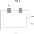
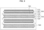
- FIGS. 2 and 3 are a schematic plan view and a schematic cross-sectional view, respectively, illustrating a lithium secondary battery in accordance with example embodiments.
- FIG. 3 is a cross-sectional view taken along a line I-I' of FIG. 2 in a thickness direction.
- the lithium secondary battery may include an anode 130 including the above-described anode active material and the cathode 100 facing the anode 130.
- the cathode 100 may include a cathode current collector 105 and a cathode active material layer 110 formed on at least one surface of the cathode current collector 105.
- the cathode current collector 105 may include stainless steel, nickel, aluminum, titanium, or an alloy thereof.
- the cathode current collector 105 may include aluminum or stainless steel surface-treated with carbon, nickel, titanium, silver, etc.
- a thickness of the cathode current collector 105 may be 10 ⁇ m to 50 ⁇ m.
- the cathode active material layer 110 may include a cathode active material.
- the cathode active material may include a compound capable of reversibly intercalating and deintercalating lithium ions.
- the cathode active material may include a lithium-nickel metal oxide.
- the lithium-nickel metal oxide may further include at least one of cobalt (Co), manganese (Mn) and aluminum (Al).
- the cathode active material or the lithium-nickel metal oxide may include a layered structure or a crystal structure represented by Chemical Formula 1. [Chemical Formula 1] Li x Ni a M b O 2+z
- M may include Co, Mn and/or Al.
- the chemical structure represented by Chemical Formula 1 represents a bonding relationship included in the layered structure or the crystal structure of the cathode active material, and does not exclude other additional elements.
- M includes Co and/or Mn
- Co and/or Mn may serve as a main active element of the cathode active material together with Ni.
- Chemical Formula 1 is provided to express the bonding relationship of the main active element and is to be understood as a formula encompassing introduction and substitution of the additional elements.
- an auxiliary element for enhancing chemical stability of the cathode active material or the layered structure/crystal structure in addition to the main active element may be further included.
- the auxiliary element may be incorporated into the layered structure/crystal structure to form a bond, and this case is to be understood as being included within the range of the chemical structure represented by Chemical Formula 1.
- the auxiliary element may include at least one of, e.g., Na, Mg, Ca, Y, Ti, Hf, V, Nb, Ta, Cr, Mo, W, Fe, Cu, Ag, Zn, B, Al, Ga, C, Si, Sn, Sr, Ba, Ra, P and Zr.
- the auxiliary element may act as an auxiliary active element such as Al that contributes to capacity/power activity of the cathode active material together with Co or Mn.
- the cathode active material or the lithium-nickel metal oxide particle may include a layered structure or a crystal structure represented by Chemical Formula 1-1.
- Chemical Formula 1-1 Li x Ni a M1 b1 M2 b2 O 2+z
- M1 may include Co, Mn and/or Al.
- M2 may include the above-described auxiliary element.
- the cathode active material may further include a coating element or a doping element.
- a coating element or a doping element For example, elements substantially the same as or similar to the above-described auxiliary elements may be used as the coating element or the doping element.
- the above-described elements may be used alone or in a combination of two or more therefrom as the coating element or the doping element.
- the doping element of the coating element may be present on a surface of the lithium-nickel metal oxide particle, or may penetrate through the surface of the lithium-nickel metal oxide particle to be included in the bonding structure represented by Chemical Formula 1 or Chemical Formula 1-1.
- the cathode active material may include a nickel-cobalt-manganese (NCM)-based lithium oxide.
- NCM nickel-cobalt-manganese
- an NCM-based lithium oxide having an increased nickel content may be used.
- Ni may be provided as a transition metal related to the power and capacity of the lithium secondary battery.
- a high-capacity cathode and a high-capacity lithium secondary battery may be implemented using a high-Ni composition in the cathode active material.
- life-span stability and capacity retention properties may be improved using Mn while maintaining an electrical conductivity by Co.
- the content of Ni in the NCM-based lithium oxide may be 0.5 or more, 0.6 or more, 0.7 or more, or 0.8 or more. In some embodiments, the content of Ni may be in a range from 0.8 to 0.95, from 0.82 to 0.95, from 0.83 to 0.95, from 0.84 to 0.95, from 0.85 to 0.95, or from 0.88 to 0.95.
- the cathode active material may include a lithium cobalt oxide-based active material, a lithium manganese oxide-based active material, a lithium nickel oxide-based active material, or a lithium iron phosphate (LFP) active material (e.g., LiFePO 4 ).
- the cathode active material may include a Li-rich layered oxide (LLO)/OLO (Over-Lithiated Oxide)-based active material, a Mn-rich active material, a Co-less-based active material, etc., which may have a chemical structure or a crystal structure represented by Chemical Formula 2 below. These may be used alone or in a combination of two or more therefrom.
- LLO Li-rich layered oxide
- OLO Over-Lithiated Oxide
- J may include at least one element from Mn, Ni, Co, Fe, Cr, V, Cu, Zn, Ti, Al, Mg and B.
- the cathode slurry may be prepared by mixing the cathode active material in a solvent.
- the cathode slurry may be coated on the cathode current collector 105, and then dried and pressed to prepare the cathode active material layer 110.
- the coating may include, e.g., a gravure coating, a slot die coating, a multi-layered simultaneous die coating, an imprinting, a doctor blade coating, a dip coating, a bar coating, a casting, etc.
- the cathode active material layer 110 may further include a binder, may optionally further include a conductive material, a thickener, etc.
- the solvent may include N-methyl-2-pyrrolidone (NMP), dimethylformamide, dimethylacetamide, N,N-dimethylaminopropylamine, ethylene oxide, tetrahydrofuran, etc.
- NMP N-methyl-2-pyrrolidone
- dimethylformamide dimethylacetamide
- N,N-dimethylaminopropylamine N,N-dimethylaminopropylamine
- ethylene oxide tetrahydrofuran, etc.
- the binder may include polyvinylidene fluoride (PVDF), vinylidene fluoride-co-hexafluoropropylene copolymer (poly(vinylidene fluoride-co-hexafluoropropylene)), polyacrylonitrile, polymethylmethacrylate, acrylonitrile butadiene rubber (NBR), polybutadiene rubber (BR), styrene-butadiene rubber (SBR), etc. These may be used alone or in a combination of two or more therefrom.
- PVDF polyvinylidene fluoride
- NBR acrylonitrile butadiene rubber
- BR polybutadiene rubber
- SBR styrene-butadiene rubber
- a PVDF-based binder may be used as the cathode binder.
- an amount of the binder for forming the cathode active material layer 110 may be reduced and an amount of the cathode active material may be relatively increased. Accordingly, the power and capacity properties of the secondary battery may be improved.
- the conductive material may be used to improve conductivity of the cathode active material layer 110 and/or mobility of lithium ions or electrons.
- the conductive material may include a carbon-based conductive material such as graphite, carbon black, acetylene black, Ketjen black, graphene, a carbon nanotube, a vapor-grown carbon fiber (VGCF), a carbon fiber and/or a metal-based conductive material such as tin, tin oxide, titanium oxide, a perovskite material including LaSrCoO 3 and LaSrMnO 3 , etc. These may be used alone or in a combination of two or more therefrom.
- the cathode slurry may further include a thickener and/or a dispersive agent.
- the cathode slurry may include the thickener such as carboxymethyl cellulose (CMC).
- the anode 130 may include an anode current collector 125, and an anode active material layer 120 formed on at least one surface of the anode current collector 125.
- the anode current collector 125 may include a copper foil, a nickel foil, a stainless steel foil, a titanium foil, a nickel foam, a copper foam, a polymer substrate coated with a conductive metal, etc. These may be used alone or in a combination of two or more therefrom.
- a thickness of the anode current collector 125 may be in a range from 10 ⁇ m to 50 ⁇ m.
- the anode active material layer 120 may include the above-described anode active material including the composite particle 50.
- the anode active material may include a plurality of the composite particles 50.
- the anode active material may include the composite particles and a graphite-based active material.
- the graphite-based active material may include artificial graphite and/or natural graphite.
- a content of the composite particles 50 based on a total weight of the anode active material may be 3 wt% or more, 5 wt% or more, 10 wt% or more, 15 wt% or more, 20 wt% or more, 25 wt% or more, 30 wt% or more, 35 wt% or more, 40 wt% or more, or 45 wt% or more.
- the content of the composite particles based on the total weight of the anode active material may be 90 wt% or less, 85 wt% or less, 80 wt% or less, 75 wt% or less, 70 wt% or less, 65 wt% or less, 60 wt% or less, 55 wt% or less, or 50 wt% or less.
- the anode active material may substantially consist of the composite particles 50 and the graphite-based active material.
- the anode active material may be mixed with a solvent to prepare an anode slurry.
- the anode slurry may be coated or deposited on the anode current collector 125, and then dried and pressed to form the anode active material layer 120.
- the coating may include a gravure coating, a slot die coating, a multi-layered simultaneous die coating, an imprinting, a doctor blade coating, a dip coating, a bar coating, a casting, etc.
- the anode active material layer 120 may further include a binder, and may optionally further include a conductive material, a thickener, etc.
- the solvent included in the anode slurry may include water, pure water, deionized water, distilled water, ethanol, isopropanol, methanol, acetone, n-propanol, t-butanol, etc. These may be used alone or in a combination of two or more therefrom.
- the above-described materials used in the fabrication of the cathode 100 may also be used as the binder, the conductive material and thickener.
- a styrene-butadiene rubber (SBR)-based binder, carboxymethyl cellulose (CMC), a polyacrylic acid-based binder, a poly(3,4-ethylenedioxythiophene (PEDOT)-based binder, etc. may be used as the anode binder. These may be used alone or in a combination of two or more therefrom.
- a separator 140 may be interposed between the cathode 100 and the anode 130.
- the separator 140 may be included to prevent an electrical short-circuiting between the cathode 100 and the anode 130 while allowing an ion flow.
- a thickness of the separator may be in a range from 10 ⁇ m to 20 ⁇ m.
- the separator 140 may include a porous polymer film or a porous non-woven fabric.
- the porous polymer film may include a polyolefin-based polymer such as an ethylene polymer, a propylene polymer, an ethylene/butene copolymer, an ethylene/hexene copolymer, an ethylene/methacrylate copolymer, etc. These may be used alone or in a combination of two or more therefrom.
- a polyolefin-based polymer such as an ethylene polymer, a propylene polymer, an ethylene/butene copolymer, an ethylene/hexene copolymer, an ethylene/methacrylate copolymer, etc.
- the porous non-woven fabric may include a high melting point glass fiber, a polyethylene terephthalate fiber, etc.
- the separator 140 may include a ceramic-based material.
- inorganic particles may be coated on the polymer film or dispersed in the polymer film to improve a heat resistance.
- the separator 140 may have a single-layered or a multi-layered structure including the polymer film and/or the non-woven fabric as described above.
- an electrode cell may be defined by the cathode 100, the anode 130 and the separator 140, and a plurality of the electrode cells may be stacked to form an electrode assembly 150 having, e.g., a jelly roll shape.
- the electrode assembly 150 may be formed by winding, stacking, z-folding, stack-folding, etc., of the separator 140.
- the electrode assembly 150 may be accommodated together with an electrolyte solution in a case 160 to define the lithium secondary battery.
- an electrolyte solution in a case 160 to define the lithium secondary battery.
- a non-aqueous electrolyte solution may be used as the electrolyte solution.
- the non-aqueous electrolyte solution may include a lithium salt serving as an electrolyte and an organic solvent.
- the lithium salt may be represented by, e.g., Li + X - , and examples of an anion X - may include F - , Cl - , Br - , I - , NO 3 - , N(CN) 2 - , BF 4 - , ClO 4 - , PF 6 - , (CF 3 ) 2 PF 4 - , (CF 3 ) 3 PF 3 - , (CF 3 ) 4 PF 2 - , (CF 3 ) 5 PF - , (CF 3 ) 6 P - , CF 3 SO 3 - , CF 3 CF 2 SO 3 - , (CF 3 SO 2 ) 2 N - , (FSO 2 ) 2 N - , CF 3 CF 2 (CF 3 ) 2 CO - , (CF 3 SO 2 ) 2
- organic solvent examples include propylene carbonate (PC), ethylene carbonate (EC), butylene carbonate, diethyl carbonate (DEC), dimethyl carbonate (DMC), ethylmethyl carbonate (EMC), methylpropyl carbonate, ethylpropyl carbonate, dipropyl carbonate, vinylene carbonate, methyl acetate (MA), ethyl acetate (EA), n-propylacetate (n-PA), 1,1-dimethylethyl acetate (DMEA), methyl propionate (MP), ethylpropionate (EP), fluoroethyl acetate (FEA), difluoroethyl acetate (DFEA), trifluoroethyl acetate (TFEA), dibutyl ether, tetraethylene glycol dimethyl ether (TEGDME), diethylene glycol dimethyl ether (DEGDME), tetrahydrofuran (THF), 2-methylty
- the non-aqueous electrolyte solution may further include an additive.
- the additive may include, e.g., a cyclic carbonate-based compound, a fluorine-substituted carbonate-based compound, a sultone-based compound, a cyclic sulfate-based compound, a cyclic sulfite-based compound, a phosphate-based compound, a borate-based compound, etc. These may be used alone or in a combination of two or more therefrom.
- the cyclic carbonate-based compound may include vinylene carbonate (VC), vinyl ethylene carbonate (VEC), etc.
- the fluorine-substituted carbonate-based compound may include fluoroethylene carbonate (FEC).
- FEC fluoroethylene carbonate
- the sultone-based compound may include 1,3-propane sultone, 1,3-propene sultone, 1,4-butane sultone, etc.
- the cyclic sulfate-based compound may include 1,2-ethylene sulfate, 1,2-propylene sulfate, etc.
- the cyclic sulfite-based compound may include ethylene sulfite, butylene sulfite, etc.
- the phosphate-based compound may include lithium difluoro bis-oxalato phosphate, lithium difluoro phosphate, etc.
- the borate-based compound may include lithium bis(oxalate) borate.
- a solid electrolyte may be used instead of the non-aqueous electrolyte solution.
- the lithium secondary battery may be manufactured in the form of an all-solid-state battery.
- a solid electrolyte layer may be disposed between the cathode 100 and the anode 130 instead of the separator 140.
- the solid electrolyte may include a sulfide-based electrolyte.
- the sulfide-based electrolyte include Li 2 S-P 2 S 5 , Li 2 S-P 2 S 5 -LiCl, Li 2 S-P 2 S 5 -LiBr, Li 2 S-P 2 S 5 -LiCl-LiBr, Li 2 S-P 2 S 5 -Li2O, Li 2 S-P 2 S 5 -Li 2 O-LiI, Li 2 S-SiS 2 , Li 2 S-SiS 2 -LiI, Li 2 S-SiS 2 -LiBr, Li 2 S-SiS 2 -LiCl, Li 2 S-SiS 2 -B 2 S 3 -LiI, Li 2 S-SiS 2 -P 2 S 5 -LiI, Li 2 S-B 2 S 3 , Li 2 S-P 2 S 5 -Z m S n (
- the solid electrolyte may include an oxide-based amorphous solid electrolyte such as Li 2 O-B 2 O 3 -P 2 O 5 , Li 2 O-SiO 2 , Li 2 O-B 2 O 3 , Li 2 O-B 2 O 3 -ZnO, etc.
- oxide-based amorphous solid electrolyte such as Li 2 O-B 2 O 3 -P 2 O 5 , Li 2 O-SiO 2 , Li 2 O-B 2 O 3 , Li 2 O-B 2 O 3 -ZnO, etc.
- electrode tabs may protrude from the cathode current collector 105 and the anode electrode current collector 125 included in each electrode cell to one side of the case 160.
- the electrode tabs may be welded together with the one side of the case 160 to form an electrode lead (a cathode lead 107 and an anode lead 127) extending or exposed to an outside of the case 160.
- the lithium secondary battery may be manufactured in, e.g., a cylindrical shape using a can, a prismatic shape, a pouch shape or a coin shape.
- Pitch and potassium acetate were dry-mixed in a weight ratio of 5:5, and a first firing was performed at 800 °C for 2 hours.
- the first fired mixture was washed with an excess of 0.5 M HCl aqueous solution to prepare carbon particles including pores.
- the carbon particles were prepared so that a specific volume of the pores of the carbon-based particles was 0.6 cm 3 /g.
- a silicon-containing gas including a silane gas and an argon gas was injected into a CVD coater at a flow rate of 50 mL/min to 100 mL/min.
- a content of the silane gas based on a total volume of the silicon-containing gas was 50 vol%.
- a temperature was increased to 550°C at a ramping rate of 5°C/min to 20°C/min, and then maintained for about 120 minutes to prepare composite particles including a silicon-containing coating.
- the composite particles were prepared so that a silicon content based on a total weight of the composite particles was 45 wt% by weight.
- anode electrode active material mixed a mixture of 15 wt% of the composite particles and 80.5 wt% of artificial graphite
- 1 wt% of CNT as a conductive material 1 wt%
- 1.5 wt% of carboxymethyl cellulose (CMC) as a thickener were mixed to obtain an anode slurry.
- the anode slurry was coated on a copper substrate, dried and pressed to obtain an anode.
- a lithium half-cell including the anode and using a lithium metal as a counter electrode (cathode) was manufactured.
- a lithium coin half-cell of a CR2016 (diameter: 20 mm, thickness: 1.6 mm) standard was formed by interposing a separator (polyethylene, thickness: 20 ⁇ m) between the anode and the lithium metal (thickness: 1 mm).
- the assembly of the lithium metal/separator/anode was placed in a coin cell plate, and a cap was covered and clamped after injecting an electrolyte solution.
- a 1 M LiPF 6 solution was formed using a mixed solvent of EC/EMC (3:7; volume ratio), and 2.0 vol% of fluoroethylene carbonate (FEC) was added based on a total volume of the electrolyte solution.
- FEC fluoroethylene carbonate
- An anode and a lithium half-cell were manufactured by the same method as that in Example 1, except that an equal amount of a silica dispersion having an average particle size of 5 nm was added instead of potassium acetate, and the washing was performed with a 0.5 M NaOH aqueous solution instead of the HCl aqueous solution.
- An anode and a lithium half-cell were manufactured by the same method as that in Example 1, except that the content of silane gas based on the total volume of silicon-containing gas was changed as shown in Table 1 below.
- An anode and a lithium half-cell were manufactured by the same method as that in Example 1, except that an equal amount of a silica dispersion having an average particle size of 5 nm was added instead of potassium acetate, the washing was performed with a 0.5 M NaOH aqueous solution instead of the HCl aqueous solution, and the content of silane gas based on the total volume of silicon-containing gas was changed as shown in Table 1 below.
- An anode and a lithium half-cell were manufactured by the same method as that in Example 1, except that an equal amount of a silica dispersion having an average particle size of 6 nm was added instead of potassium acetate, and the washing was performed with a 0.5 M NaOH aqueous solution instead of the HCl aqueous solution,
- the carbon-based particles having the silicon-containing coating formed thereon were introduced into a thermal CVD chamber, and then a mixed gas of ethylene gas and argon was supplied and heat-treated at a temperature less than 600°C to produce composite particles having a carbon coating formed on the silicon-containing coating.
- an anode and a lithium half-cell were manufactured by the same method as that in in Example 1.
- An anode and a lithium half-cell were manufactured by the same method as that in Example 1, except that an equal amount of a silica dispersion having an average particle size of 3 nm was added instead of potassium acetate, the washing was performed with a 0.5 M NaOH aqueous solution instead of the HCl aqueous solution, and the content of silane gas based on the total volume of silicon-containing gas was changed as shown in Table 1 below.
- An anode and a lithium half-cell were manufactured by the same method as that in Example 1, except that an equal amount of a silica dispersion having an average particle size of 6 nm was added instead of potassium acetate, the washing was performed with a 0.5 M NaOH aqueous solution instead of the HCl aqueous solution, and the content of silane gas based on the total volume of silicon-containing gas was changed as shown in Table 1 below.
- An anode and a lithium half-cell were manufactured by the same method as that in Example 1, except that an equal amount of a silica dispersion having an average particle size of 10 nm was added instead of potassium acetate, and the washing was performed with a 0.5 M NaOH aqueous solution instead of the HCl aqueous solution.
- An anode and a lithium half-cell were manufactured by the same method as that in Example 1, except that an equal amount of a silica dispersion having an average particle size of 50 nm was added instead of potassium acetate, and the washing was performed with a 0.5 M NaOH aqueous solution instead of the HCl aqueous solution.
- An anode and a lithium half-cell were manufactured by the same method as that in Example 1, except that an equal amount of a dispersion of silica having an average particle size of 100 nm was added instead of potassium acetate, and washing was performed with a 0.5 M NaOH aqueous solution instead of an HCl aqueous solution.
- Pore sizes of the carbon-based particles according to Examples and Comparative Examples were measured using a surface area analyzer (ASAP-2420) from Micromeritics. Specifically, the pore size of the carbon-based particles was measured by measuring a maximum peak position in a Barrett-Joyner-Halenda (BJH) pore size distribution curve obtained from a nitrogen gas sorption isotherm of each sample obtained from Examples and Comparative Examples.
- SASAP-2420 surface area analyzer
- BJH Barrett-Joyner-Halenda
- the sample was placed in an inductively coupled plasma spectroscopy analyzer (ICP-OES Optima 8300, Perkin Elmer Co.) and analyzed to measure a silicon content based on a total weight of the composite particles.
- ICP-OES Optima 8300 Perkin Elmer Co.
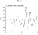
- a PDF analysis was performed on the composite particles according to Examples and Comparative Examples to obtain a PDF spectrum graph in which a vertical axis was a PDF function G(r) and a horizontal axis was r ( ⁇ ) corresponding to an interatomic distance.
- scattering data for the PDF analysis were collected from a beam line 1C of Pohang Light Source (PLS-II) of Pohang Accelerator Laboratory (PAL).
- PLS-II Pohang Light Source
- PAL Pohang Accelerator Laboratory
- a sample of the composite particles was introduced into a capillary, and the scattering data including 2D scattering images was measured at a step size of 0.017 degree in a range of 5 to 80 degrees (2 ⁇ ) using a high energy X-ray (22.003 KeV) with a wavelength ( ⁇ ) of 0.56356 ⁇ .
- the 2D scattering images were integrated using a software (Dioptas) to obtain 1D scattering intensity data.
- a diffraction peak of the collector was planarized when the collector and the composite particles were adhered.
- An X-ray scattered by the hollow capillary can be collected to obtain background data.
- the 1D scattering intensity data, the background data, the used wavelength and the chemical composition were applied to a software (PDFgetX3) to obtain a structure function S(Q).
- a relative intensity (background scale) of the background data compared to the 1D scattering intensity data was set to 1.0, and a range of Q was set to 0.1 to 12.0.
- the S(Q) was Fourier transformed to obtain a G(r) function, and changes in G(r) according to the interatomic distance (r) was plotted to obtain the PDF spectrum.
- a baseline was drawn to be parallel to the horizontal axis (r) based on a height of the vertical axis (G(r)) when r of the PDF spectrum was 0 ⁇ , and then a central peak value of a peak having a maximum height in a range from 3.4 ⁇ to 4.1 ⁇ based on the baseline was derived as p1, and a central peak value of a peak having a maximum height in a range from 4.1 ⁇ to 4.9 ⁇ was derived as p2.
- a peak distance was calculated by substituting p1 and p2 into Equation 1.
- the peak height of p1 was determined as Ip1, and the peak height of p2 was determined as Ip2.
- the Ip1 and Ip2 were substituted into Equation 2 to calculate the peak intensity ratio.
- FIG. 4 is a PDF spectrum graph obtained by a PDF analysis of Example 5.
- FIG. 5 is a PDF spectrum graph obtained by a PDF analysis of Comparative Example 5.
- the lithium half-cell according to Examples and Comparative Examples was charged (CC/CV 0.5C 0.01V 0.01C CUT-OFF) and discharged (CC 0.1C 3.0V CUT-OFF) by 50 cycles, and a capacity retention was evaluated as a percentage of a discharge capacity at the 50th cycle relative to a discharge capacity at the 1st cycle.
- the silicon contents based on the total weight of the composite particles were substantially similar, but the physical and life-span properties of the composite particles were measured as being different according to the pore size and the silane gas concentration.
- Example 6 where the pore size of the carbon-based particles was greater than 10 nm, the capacity retention was lowered compared to those from other Examples.
- Example 10 where the carbon coating was further formed on the silicon-containing coating, the capacity retention was improved compared to those from other Examples.
Landscapes
- Chemical & Material Sciences (AREA)
- Chemical Kinetics & Catalysis (AREA)
- Electrochemistry (AREA)
- General Chemical & Material Sciences (AREA)
- Composite Materials (AREA)
- Inorganic Chemistry (AREA)
- Engineering & Computer Science (AREA)
- Manufacturing & Machinery (AREA)
- Organic Chemistry (AREA)
- Materials Engineering (AREA)
- Battery Electrode And Active Subsutance (AREA)
Applications Claiming Priority (1)
| Application Number | Priority Date | Filing Date | Title |
|---|---|---|---|
| KR1020230171126A KR20250082615A (ko) | 2023-11-30 | 2023-11-30 | 리튬 이차 전지용 음극 활물질 및 이를 포함하는 리튬 이차 전지 |
Publications (2)
| Publication Number | Publication Date |
|---|---|
| EP4564454A2 true EP4564454A2 (de) | 2025-06-04 |
| EP4564454A3 EP4564454A3 (de) | 2025-06-18 |
Family
ID=93743802
Family Applications (1)
| Application Number | Title | Priority Date | Filing Date |
|---|---|---|---|
| EP24216684.1A Pending EP4564454A3 (de) | 2023-11-30 | 2024-11-29 | Anodenaktivmaterial für lithiumsekundärbatterie und lithiumsekundärbatterie damit |
Country Status (4)
| Country | Link |
|---|---|
| US (1) | US20250183303A1 (de) |
| EP (1) | EP4564454A3 (de) |
| KR (1) | KR20250082615A (de) |
| CN (1) | CN120072880A (de) |
Family Cites Families (3)
| Publication number | Priority date | Publication date | Assignee | Title |
|---|---|---|---|---|
| US20120264020A1 (en) * | 2010-10-07 | 2012-10-18 | Applied Sciences, Inc. | Method of depositing silicon on carbon nanomaterials |
| EP4593140A3 (de) * | 2021-09-07 | 2025-12-24 | Sila Nanotechnologies Inc. | Batterieanode mit kohlenstoff und optional silizium mit der durch röntgenstrahlbeugung geschätzten kohlenstoffdomänengrösse |
| CN116706024A (zh) * | 2023-06-29 | 2023-09-05 | 宁德新能源科技有限公司 | 负极材料、负极极片、电化学装置、用电设备 |
-
2023
- 2023-11-30 KR KR1020230171126A patent/KR20250082615A/ko active Pending
-
2024
- 2024-11-21 US US18/954,536 patent/US20250183303A1/en active Pending
- 2024-11-22 CN CN202411678046.9A patent/CN120072880A/zh active Pending
- 2024-11-29 EP EP24216684.1A patent/EP4564454A3/de active Pending
Also Published As
| Publication number | Publication date |
|---|---|
| KR20250082615A (ko) | 2025-06-09 |
| EP4564454A3 (de) | 2025-06-18 |
| CN120072880A (zh) | 2025-05-30 |
| US20250183303A1 (en) | 2025-06-05 |
Similar Documents
| Publication | Publication Date | Title |
|---|---|---|
| EP4431455A1 (de) | Anodenaktivmaterial für lithiumsekundärbatterie und lithiumsekundärbatterie damit | |
| US20240194861A1 (en) | Anode for lithium secondary battery and lithium secondary battery including the same | |
| EP4553917A1 (de) | Anodenaktivmaterial für eine lithiumsekundärbatterie und lithiumsekundärbatterie damit | |
| EP4564455A2 (de) | Anode für lithiumsekundärbatterie und lithiumsekundärbatterie damit | |
| EP4564454A2 (de) | Anodenaktivmaterial für lithiumsekundärbatterie und lithiumsekundärbatterie damit | |
| EP4564453A2 (de) | Anode für lithiumsekundärbatterie und lithiumsekundärbatterie damit | |
| EP4564461A2 (de) | Anodenaktivmaterial für lithiumsekundärbatterie und lithiumsekundärbatterie damit | |
| EP4586335A1 (de) | Anodenaktivmaterial für lithiumsekundärbatterie und lithiumsekundärbatterie damit | |
| EP4564459A2 (de) | Anode für lithiumsekundärbatterie und lithiumsekundärbatterie damit | |
| EP4576252A1 (de) | Lithiumsekundärbatterie | |
| EP4621857A1 (de) | Anodenaktivmaterial für lithiumsekundärbatterie, verfahren zur herstellung davon und lithiumsekundärbatterie damit | |
| EP4697405A1 (de) | Anodenaktivmaterial für sekundärbatterie und sekundärbatterie damit | |
| EP4708393A1 (de) | Anodenaktivmaterial für sekundärbatterie und sekundärbatterie selbiges umfassend | |
| EP4450460A1 (de) | Anodenaktivmaterial für lithiumsekundärbatterie und lithiumsekundärbatterie damit | |
| EP4583202A1 (de) | Anodenaktivmaterial für lithiumsekundärbatterie und lithiumsekundärbatterie damit | |
| EP4586333A1 (de) | Kathode für lithiumsekundärbatterie und lithiumsekundärbatterie damit | |
| EP4579790A1 (de) | Anode für lithiumsekundärbatterie und lithiumsekundärbatterie damit | |
| EP4648132A1 (de) | Anodenaktivmaterial für lithiumsekundärbatterie, verfahren zur herstellung davon und lithiumsekundärbatterie damit | |
| EP4603460A1 (de) | Kathodenaktivmaterial für lithiumsekundärbatterie und lithiumsekundärbatterie damit | |
| EP4506310A1 (de) | Kathodenaktivmaterial für lithiumsekundärbatterie, verfahren zur herstellung davon und lithiumsekundärbatterie damit | |
| KR20250040295A (ko) | 리튬 이차 전지용 양극 활물질 및 이를 포함하는 리튬 이차 전지 | |
| KR20250084030A (ko) | 리튬 이차 전지용 음극 및 이를 포함하는 리튬 이차 전지 | |
| KR20250155839A (ko) | 리튬 이차 전지용 양극 활물질, 이의 제조 방법 및 이를 포함하는 리튬 이차 전지 | |
| CN121641843A (zh) | 锂二次电池用正极及包括该正极的锂二次电池 |
Legal Events
| Date | Code | Title | Description |
|---|---|---|---|
| PUAI | Public reference made under article 153(3) epc to a published international application that has entered the european phase |
Free format text: ORIGINAL CODE: 0009012 |
|
| STAA | Information on the status of an ep patent application or granted ep patent |
Free format text: STATUS: REQUEST FOR EXAMINATION WAS MADE |
|
| PUAL | Search report despatched |
Free format text: ORIGINAL CODE: 0009013 |
|
| 17P | Request for examination filed |
Effective date: 20241129 |
|
| AK | Designated contracting states |
Kind code of ref document: A2 Designated state(s): AL AT BE BG CH CY CZ DE DK EE ES FI FR GB GR HR HU IE IS IT LI LT LU LV MC ME MK MT NL NO PL PT RO RS SE SI SK SM TR |
|
| AK | Designated contracting states |
Kind code of ref document: A3 Designated state(s): AL AT BE BG CH CY CZ DE DK EE ES FI FR GB GR HR HU IE IS IT LI LT LU LV MC ME MK MT NL NO PL PT RO RS SE SI SK SM TR |
|
| RIC1 | Information provided on ipc code assigned before grant |
Ipc: H01M 4/62 20060101ALI20250512BHEP Ipc: H01M 4/587 20100101ALI20250512BHEP Ipc: H01M 4/133 20100101AFI20250512BHEP |