EP4564374A1 - Nuclear fuel assembly spacer grid - Google Patents
Nuclear fuel assembly spacer grid Download PDFInfo
- Publication number
- EP4564374A1 EP4564374A1 EP23307114.1A EP23307114A EP4564374A1 EP 4564374 A1 EP4564374 A1 EP 4564374A1 EP 23307114 A EP23307114 A EP 23307114A EP 4564374 A1 EP4564374 A1 EP 4564374A1
- Authority
- EP
- European Patent Office
- Prior art keywords
- spacer grid
- peripheral strip
- peripheral
- fuel assembly
- reinforcing part
- Prior art date
- Legal status (The legal status is an assumption and is not a legal conclusion. Google has not performed a legal analysis and makes no representation as to the accuracy of the status listed.)
- Pending
Links
Images



Classifications
-
- G—PHYSICS
- G21—NUCLEAR PHYSICS; NUCLEAR ENGINEERING
- G21C—NUCLEAR REACTORS
- G21C3/00—Reactor fuel elements and their assemblies; Selection of substances for use as reactor fuel elements
- G21C3/30—Assemblies of a number of fuel elements in the form of a rigid unit
- G21C3/32—Bundles of parallel pin-, rod-, or tube-shaped fuel elements
- G21C3/34—Spacer grids
- G21C3/356—Spacer grids being provided with fuel element supporting members
- G21C3/3563—Supporting members formed only by deformations in the strips
-
- G—PHYSICS
- G21—NUCLEAR PHYSICS; NUCLEAR ENGINEERING
- G21C—NUCLEAR REACTORS
- G21C3/00—Reactor fuel elements and their assemblies; Selection of substances for use as reactor fuel elements
- G21C3/30—Assemblies of a number of fuel elements in the form of a rigid unit
- G21C3/32—Bundles of parallel pin-, rod-, or tube-shaped fuel elements
- G21C3/34—Spacer grids
- G21C3/356—Spacer grids being provided with fuel element supporting members
- G21C3/3566—Supporting members formed only of elements fixed on the strips
-
- G—PHYSICS
- G21—NUCLEAR PHYSICS; NUCLEAR ENGINEERING
- G21C—NUCLEAR REACTORS
- G21C3/00—Reactor fuel elements and their assemblies; Selection of substances for use as reactor fuel elements
- G21C3/30—Assemblies of a number of fuel elements in the form of a rigid unit
- G21C3/32—Bundles of parallel pin-, rod-, or tube-shaped fuel elements
- G21C3/34—Spacer grids
- G21C3/352—Spacer grids formed of assembled intersecting strips
-
- Y—GENERAL TAGGING OF NEW TECHNOLOGICAL DEVELOPMENTS; GENERAL TAGGING OF CROSS-SECTIONAL TECHNOLOGIES SPANNING OVER SEVERAL SECTIONS OF THE IPC; TECHNICAL SUBJECTS COVERED BY FORMER USPC CROSS-REFERENCE ART COLLECTIONS [XRACs] AND DIGESTS
- Y02—TECHNOLOGIES OR APPLICATIONS FOR MITIGATION OR ADAPTATION AGAINST CLIMATE CHANGE
- Y02E—REDUCTION OF GREENHOUSE GAS [GHG] EMISSIONS, RELATED TO ENERGY GENERATION, TRANSMISSION OR DISTRIBUTION
- Y02E30/00—Energy generation of nuclear origin
- Y02E30/30—Nuclear fission reactors
Definitions
- the present invention relates to the field of spacer grids configured for receiving fuel rods to form a fuel assembly of a nuclear power plant.
- the present invention relates in particular to a nuclear fuel assembly spacer grid defining a lattice of cells for receiving fuel rods, wherein the spacer grid comprises a peripheral band composed of at least one peripheral strip delimiting a portion of a peripheral contour of the spacer grid, wherein at least one peripheral strip defines a protruding protrusion.
- protrusions are generally configured to cooperate with a fuel assembly support of the nuclear power plant and contribute for example in an accurate positioning of the fuel assembly in the nuclear power plant.
- Known protrusions of such spacer grids are typically obtained by stamping a strip that forms a peripheral strip of the spacer grid. Such stamped protrusions allow the peripheral grid to cooperate with other elements of the nuclear power plant, such as for example the fuel assembly support, at defined location.
- spacer grids are however not entirely satisfying. Indeed, spacer grids are generally arranged in an environment exposed to vibrations. This generally leads to a gradual wear of the protrusions, which may in turns lead to forming openings in the spacer grid. This can lead to a degradation of the intended function of the spacer grid protrusions.
- a goal of the invention is therefore to obtain a spacer grid which improves the performance and longevity of the spacer grid protrusions, thus maintaining the as designed mechanical behavior of the fuel assembly.
- the invention relates to a nuclear fuel assembly spacer grid as above mentioned, wherein the protruding protrusion further comprises a reinforcing part, the thickness of the protrusion being superior to the thickness of the peripheral strip.
- Such a spacer grid is especially advantageous since the reinforcing part of the protruding protrusion prevents the degradation of the intended function of the peripheral band of the spacer grid without increase of the thickness for the entire peripheral band and thus without significant reduction of the neutronic efficiency around the fuel rods and increased pressure loss of the component. This leads to improving the mechanical behavior of the fuel assembly without compromising its performances.
- the spacer grid further comprises one or several of the features mentioned below, considered independently or along any technically possible combination:
- a nuclear reactor 10 is represented.
- the nuclear reactor 10 is for example a Pressurized Water Reactor (abbreviated PWR).
- the nuclear reactor 10 is a Boiling Water Reactor (abbreviated BWR) or a Water Water Energy Reactor (abbreviated WER or VVER).
- the nuclear reactor 10 comprises a nuclear fuel assembly 12 and comprises for example a fuel assembly support 14.
- the fuel assembly support 14 is for example configured to position the nuclear fuel assembly 12 in the nuclear reactor 10.
- the fuel assembly support 14 is dedicated to position the nuclear fuel assembly 12 in the nuclear power plant 10.
- the fuel assembly support 14 corresponds to any part of the nuclear power plant cooperating with the nuclear fuel assembly 12.
- the nuclear fuel assembly 12 comprises a nuclear fuel assembly spacer grid 16, called hereinafter spacer grid 16, and comprises for example fuel rods 18, arranged in the spacer grid 16. For clarity purposes, only one fuel rod is illustrated on figure 1 .
- the spacer grid 16 defines a lattice of cells 20 for receiving the fuel rods 18.
- the cells 20 are configured to host and maintain fuel rods 18 in the spacer grid 16.
- the spacer grid 16 defines for example a lattice of between 5 and 50 cells in a first direction and between 5 and 50 cells in a second direction.
- the spacer grid 16 defines a lattice of eleven cells in a first direction and of eleven cells in another direction, such spacer grid 16 defining 121 cells.
- Each cell 20 defines for example a cell direction C-C', each fuel rod 18 being arranged in a cell 20 such that the fuel rod 18 is elongated along the cell direction C-C'.
- the spacer grid 16 comprises a peripheral band 22 delimiting a peripheral contour 24 of the spacer grid 16.
- the peripheral band 22 comprises for example at least one peripheral strip 26, the or each peripheral strip 26 defining a portion of the peripheral contour 24 of the spacer grid 16.
- the peripheral band 22 comprises four peripheral strips 26, fastened between them to form the peripheral band 22.
- the peripheral strips 26 are for example welded between them to form the peripheral band 22.
- the peripheral strip 26 defines a protruding protrusion 28.
- the peripheral strip 26 comprises at least a dimple 30 and/or an orifice 31.
- the peripheral strip 26 also comprises for example at least one positioning spring 32 and at least one guiding projection 34.
- the peripheral strip 26 further comprises a fuel rod spring 36.
- the guiding projections 34 project from the rest of the peripheral band 22 along the cell direction C-C'.
- the guiding projections are for example extending in the continuity of the rest of the peripheral band 22.
- the guiding projections 34 are for example bent inwards toward the lattice of cells 20.
- the guiding projections 34 are for example configured to guide and/or maintain the fuel rods in the spacer grid 16 and are for example configured to extend at least partially between two adjacent fuel rods 18.
- the positioning spring 32 and the fuel rod spring 36 are for example formed in the peripheral strip 26.
- the positioning spring 32 and the fuel rod springs are elastically deformable.
- the peripheral strip 26 comprises for example a slit 38, for example of curved shape, the or each slit defining a positioning spring 32 or a fuel rod spring 36.
- the positioning springs 32 and the fuel rod springs 36 thus for example comprise a tongueshaped portion of the peripheral strip 26.
- the fuel rod springs 36 are for example configured to cooperate with the fuel rods arranged in cells 20 adjacent to such springs 36.
- the peripheral strip 26 comprises nine fuel rods spring 36 that are configured to cooperate with nine fuel centered relative to the peripheral strip 26.
- each peripheral strip 26 comprises for example two positioning springs 32.
- the positioning springs 32 of each peripheral strips 26 are arranged at opposed ends of the peripheral strip 26.
- the protruding protrusion 28 is defined by the peripheral strip 26.
- the protruding protrusion 28 comprises a portion of the peripheral strip 26.
- the protruding protrusion 28 further comprises a reinforcing part 40.
- the protruding protrusion 28 is for example formed by the superposition of the reinforcing part 40 and of the peripheral strip 26.
- the protruding protrusion is formed by the reinforcing part 40 and the portion of the peripheral strip 26 which is adjacent and/or in contact with the reinforcing part 40.
- the thickness TP of the protrusion 28 is superior to the thickness TS of the peripheral strip.
- the thickness TP of the protrusion corresponds to the sum of the thickness TS of the peripheral strip 26 and of the thickness of the reinforcing part 40.
- the thickness TP of the protrusion 26 is for example between 1,5 and 5 times bigger than the thickness TS to the peripheral strip 26.
- each peripheral strip 26 of the peripheral band 22 comprises for example at least two protruding protrusions 28.
- each peripheral strip 26 of the peripheral band comprises two protruding protrusions 28.
- the protruding protrusions 28 are arranged at opposed ends of the peripheral strip 26.
- the protruding protrusion 28 protrudes for example from the peripheral band 22, that is, from the rest of the peripheral band 22, inwardly or outwardly.
- the protrusions protrude from the spacer grid 16 outwardly, that is away from the lattice of cells 20.
- the protruding protrusions 26 protrude towards the fuel assembly support 14 to cooperate with the fuel assembly support 14.
- the at least one peripheral strip 26 defines the protruding protrusion 28 on the positioning spring 32.
- the peripheral strip 26 comprises a protrusion arranged on the positioning spring 32, for example outwardly protruding for cooperating with the fuel assembly support 14.
- the at least one peripheral strip 26 defines the protruding protrusion 28 on the fuel rod spring 36.
- the peripheral strip 26 comprises a protrusion arranged on the fuel rod spring 36, for example inwardly protruding for cooperating with one of the fuel rods 18.
- the reinforcing part 40 is for example obtained by milling and/or additive manufacturing and/or stamping.
- the reinforcing part 40 is for example riveted and/or welded on the peripheral strip 26.
- the peripheral strip 26 comprises a dimple 30.
- the dimple 30 defines a cavity 42 and the reinforcing part 40 is for example arranged in the cavity 42 to form the protruding protrusion 28.
- the reinforcing part 40 is arranged on the peripheral strip 26, opposed to the cavity 42.
- the reinforcing part is for example arranged on an inside face I of the peripheral strip 26, as illustrated for example on figures 3 and 4 , or on an outside face O of the peripheral strip 26, as illustrated for example on figures 5 , 6 and 7 .
- the peripheral strip 26 comprises an orifice 31.
- the reinforcing part 40 then comprises a projecting portion 44, projecting from the rest of the reinforcing part 40.
- the projecting portion 44 is engaged in the orifice 31 to form the protrusion 28.
- the peripheral strip 26 comprises a dimple 30, for example stamped in the peripheral strip 26.
- the reinforcing part 40 is obtained by the stamping of a sheet of material such as for example stainless steel.
- the reinforcing part 40 is then arranged in the cavity of the dimple 30, as illustrated in figure 3 , or outside of the dimple 30, as illustrated in figure 7 , to form the protruding protrusion 28.
- the reinforcing part is for example welded to the peripheral strip 26 along welding joints 46.
- the peripheral strip 26 also comprises a dimple 30.
- the reinforcing part 40 is however obtained by additive manufacturing.
- the shape of the reinforcing part is for example complementary to the shape of the cavity 42.
- the reinforcing part is then for example welded in the cavity 42.
- the reinforcing part is formed directly in the cavity 40.
- the peripheral strip 26 does not comprise any dimple 30.
- the reinforcing part is arranged on a substantially flat portion 48 of the peripheral strip 26.
- the reinforcing part 40 is for example obtained by additive manufacturing.
- the reinforcing part 40 is for example welded on the peripheral strip or formed directly on the peripheral strip 26.
- the reinforcing part 40 is for example obtained by additive manufacturing and machining.
- the projecting portion 44 of the reinforcing part 40 is for example engaged in the orifice 31 of the peripheral trip 26 and the reinforcing part 40 is then welded on the peripheral strip 26, as illustrated from the welding bead illustrated on figure 6 .
- the reinforcing part 40 is riveted on the peripheral strip 26 through the orifice 31.
- protruding protrusions 28 further comprising a reinforcing part 40, and having the thickness TP of the protrusion 28 being superior to the thickness TS of the peripheral strip 26 is especially advantageous to maintain the performance and longevity of the peripheral strip 26 without compromising the performances of the fuel assembly 12, in particular by preventing a formation of holes in the peripheral strip.
- protruding protrusion 28 on the positioning spring 32 is especially advantageous for limiting the wear of the protrusions 28 and for improving the positioning of the nuclear fuel assembly 12.
- Having at least two protruding protrusions 28 on the peripheral strip 26 and/or protrusions protruding away from the lattice of cells 20 further improves the positioning of the nuclear fuel assembly 12.
- Arranging the reinforcing part 40 in the cavity 42 of a dimple 30 is especially advantageous to reinforce existing spacer grids 16.
- a reinforcing part 40 comprising a projecting portion 44 engaged in the orifice 31 of a peripheral strip 26 is especially advantageous since it ensures an easy fastening of the reinforcing part to the peripheral strip 26. Furthermore, when the reinforcing part 40 is welded on the peripheral strip 26, the welding is for example localized around the projecting portion 44, limiting the distortions resulting from the welding.
Landscapes
- Physics & Mathematics (AREA)
- Engineering & Computer Science (AREA)
- Plasma & Fusion (AREA)
- General Engineering & Computer Science (AREA)
- High Energy & Nuclear Physics (AREA)
- Fuel-Injection Apparatus (AREA)
Abstract
This nuclear fuel assembly spacer grid (16) defines a lattice of cells (20) for receiving fuel rods (18), wherein the spacer grid (16) comprises a peripheral band (22) composed of at least one peripheral strip (26) delimiting a portion of a peripheral contour (24) of the spacer grid (16), wherein at least one peripheral strip (26) defines a protruding protrusion (28). The protruding protrusion (28) further comprises a reinforcing part, the thickness of the protrusion (28) being superior to the thickness of the peripheral strip (26)
Description
- The present invention relates to the field of spacer grids configured for receiving fuel rods to form a fuel assembly of a nuclear power plant. The present invention relates in particular to a nuclear fuel assembly spacer grid defining a lattice of cells for receiving fuel rods, wherein the spacer grid comprises a peripheral band composed of at least one peripheral strip delimiting a portion of a peripheral contour of the spacer grid, wherein at least one peripheral strip defines a protruding protrusion.
- In the domain of spacer grids, one knows to have a peripheral band comprising a protruding protrusion. Such protrusions are generally configured to cooperate with a fuel assembly support of the nuclear power plant and contribute for example in an accurate positioning of the fuel assembly in the nuclear power plant.
- Known protrusions of such spacer grids are typically obtained by stamping a strip that forms a peripheral strip of the spacer grid. Such stamped protrusions allow the peripheral grid to cooperate with other elements of the nuclear power plant, such as for example the fuel assembly support, at defined location.
- Such known spacer grids are however not entirely satisfying. Indeed, spacer grids are generally arranged in an environment exposed to vibrations. This generally leads to a gradual wear of the protrusions, which may in turns lead to forming openings in the spacer grid. This can lead to a degradation of the intended function of the spacer grid protrusions.
- Known solutions comprise the use of spacer grids using thicker peripheral bands. However, such spacer grids reduce neutronic efficiency around the fuel rods or cause higher pressure loss of the component, leading to reduced performance of the fuel assembly comprising the spacer grid.
- A goal of the invention is therefore to obtain a spacer grid which improves the performance and longevity of the spacer grid protrusions, thus maintaining the as designed mechanical behavior of the fuel assembly.
- To that end, the invention relates to a nuclear fuel assembly spacer grid as above mentioned, wherein the protruding protrusion further comprises a reinforcing part, the thickness of the protrusion being superior to the thickness of the peripheral strip.
- Such a spacer grid is especially advantageous since the reinforcing part of the protruding protrusion prevents the degradation of the intended function of the peripheral band of the spacer grid without increase of the thickness for the entire peripheral band and thus without significant reduction of the neutronic efficiency around the fuel rods and increased pressure loss of the component. This leads to improving the mechanical behavior of the fuel assembly without compromising its performances.
- According to specific embodiments of the invention, the spacer grid further comprises one or several of the features mentioned below, considered independently or along any technically possible combination:
- the spacer grid comprises at least one positioning spring elastically deformable and formed in the peripheral strip, the at least one peripheral strip defining the protruding protrusion on the positioning spring;
- each peripheral strip of the peripheral band defines at least two protruding protrusions;
- the protruding protrusion protrudes from the spacer grid away from the lattice of cells;
- the protruding protrusion is formed by the superposition of the reinforcing part and of the peripheral strip;
- the peripheral strip comprises a dimple defining a cavity, the reinforcing part being arranged in the cavity or on the peripheral strip, opposed to the cavity, to form the protruding protrusion;
- the reinforcing part is welded on the peripheral strip;
- the reinforcing part is riveted on the peripheral strip;
- the reinforcing part is obtained by milling and/or additive manufacturing and/or stamping; and
- the peripheral strip comprises an orifice and the reinforcing part comprises a projecting portion, the projecting portion being engaged in the orifice to form the protruding protrusion.
- Other features and advantages of the invention will become apparent from a detailed description which is given thereof below, as an indication and by no means as a limitation, with reference to the appended figures, wherein:
-
Figure 1 is a schematic top view of a nuclear fuel assembly spacer grid according to the invention; -
Figure 2 is a schematic lateral view of the spacer grid offigure 1 , and more particularly of the peripheral strip of such a spacer grid; -
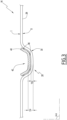
Figure 3 is a schematic section view, along a section plane A-A, of a detail of peripheral strip of a spacer grid according to a first embodiment of the invention; -
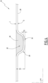
Figure 4 is a schematic view similar to the view ofFigure 3 of a peripheral strip of a spacer grid according to a second embodiment of the invention; -
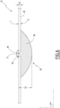
Figure 5 is a schematic view similar to the view ofFigures 3 and4 of a peripheral strip of a spacer grid according to a third embodiment of the invention; -
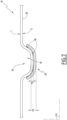
Figure 6 is a schematic view similar to the view ofFigures 3 to 5 of a peripheral strip of a spacer grid according to a fourth embodiment of the invention; and -
Figure 7 is a schematic view similar to the view ofFigures 3 to 6 of a peripheral strip of a spacer grid according to a fifth embodiment of the invention. - Referring to
figure 1 , anuclear reactor 10 is represented. Thenuclear reactor 10 is for example a Pressurized Water Reactor (abbreviated PWR). In other examples, thenuclear reactor 10 is a Boiling Water Reactor (abbreviated BWR) or a Water Water Energy Reactor (abbreviated WWER or VVER). - As visible from
figure 1 , thenuclear reactor 10 comprises anuclear fuel assembly 12 and comprises for example afuel assembly support 14. - The
fuel assembly support 14 is for example configured to position thenuclear fuel assembly 12 in thenuclear reactor 10. For example, thefuel assembly support 14 is dedicated to position thenuclear fuel assembly 12 in thenuclear power plant 10. In other example, thefuel assembly support 14 corresponds to any part of the nuclear power plant cooperating with thenuclear fuel assembly 12. - As illustrated on
figure 1 , thenuclear fuel assembly 12 comprises a nuclear fuelassembly spacer grid 16, called hereinafterspacer grid 16, and comprises forexample fuel rods 18, arranged in thespacer grid 16. For clarity purposes, only one fuel rod is illustrated onfigure 1 . - As illustrated in
figure 1 , thespacer grid 16 defines a lattice ofcells 20 for receiving thefuel rods 18. For example, and as illustrated for onefuel rod 18 infigure 1 , thecells 20 are configured to host and maintainfuel rods 18 in thespacer grid 16. Thespacer grid 16 defines for example a lattice of between 5 and 50 cells in a first direction and between 5 and 50 cells in a second direction. In the example offigure 1 , thespacer grid 16 defines a lattice of eleven cells in a first direction and of eleven cells in another direction,such spacer grid 16 defining 121 cells. - Each
cell 20 defines for example a cell direction C-C', eachfuel rod 18 being arranged in acell 20 such that thefuel rod 18 is elongated along the cell direction C-C'. - As visible from
figure 1 and as illustrated in more details onfigure 2 , thespacer grid 16 comprises aperipheral band 22 delimiting aperipheral contour 24 of thespacer grid 16. - The
peripheral band 22 comprises for example at least oneperipheral strip 26, the or eachperipheral strip 26 defining a portion of theperipheral contour 24 of thespacer grid 16. - In the example presented in
figures 1 and2 , theperipheral band 22 comprises fourperipheral strips 26, fastened between them to form theperipheral band 22. Theperipheral strips 26 are for example welded between them to form theperipheral band 22. - As illustrated in
figures 1 and2 , and as presented in more details infigures 3 to 7 , theperipheral strip 26 defines aprotruding protrusion 28. In some examples, theperipheral strip 26 comprises at least a dimple 30 and/or anorifice 31. Theperipheral strip 26 also comprises for example at least onepositioning spring 32 and at least one guidingprojection 34. In the example presented infigure 2 , theperipheral strip 26 further comprises afuel rod spring 36. - As illustrated in
figure 2 , the guidingprojections 34 project from the rest of theperipheral band 22 along the cell direction C-C'. The guiding projections are for example extending in the continuity of the rest of theperipheral band 22. Furthermore, the guidingprojections 34 are for example bent inwards toward the lattice ofcells 20. The guidingprojections 34 are for example configured to guide and/or maintain the fuel rods in thespacer grid 16 and are for example configured to extend at least partially between twoadjacent fuel rods 18. - The
positioning spring 32 and thefuel rod spring 36 are for example formed in theperipheral strip 26. Thepositioning spring 32 and the fuel rod springs are elastically deformable. Theperipheral strip 26 comprises for example aslit 38, for example of curved shape, the or each slit defining apositioning spring 32 or afuel rod spring 36. The positioning springs 32 and thefuel rod springs 36 thus for example comprise a tongueshaped portion of theperipheral strip 26. - The
fuel rod springs 36 are for example configured to cooperate with the fuel rods arranged incells 20 adjacent tosuch springs 36. In the example offigure 2 , theperipheral strip 26 comprises nine fuel rods spring 36 that are configured to cooperate with nine fuel centered relative to theperipheral strip 26. - The
positioning spring 32 is for example configured to cooperate with thenuclear reactor 10 to support thenuclear fuel assembly 12 in thereactor 10. For example, the positioning spring is configured to cooperate with thefuel assembly support 14 as presented infigure 1 . As visible fromfigures 1 and2 , eachperipheral strip 26 comprises for example two positioning springs 32. In this example, the positioning springs 32 of each peripheral strips 26 are arranged at opposed ends of theperipheral strip 26. - As presented above, the protruding
protrusion 28 is defined by theperipheral strip 26. In other words, the protrudingprotrusion 28 comprises a portion of theperipheral strip 26. - As illustrated in
figures 3 to 7 , the protrudingprotrusion 28 further comprises a reinforcingpart 40. The protrudingprotrusion 28 is for example formed by the superposition of the reinforcingpart 40 and of theperipheral strip 26. For example, the protruding protrusion is formed by the reinforcingpart 40 and the portion of theperipheral strip 26 which is adjacent and/or in contact with the reinforcingpart 40. - The thickness TP of the
protrusion 28 is superior to the thickness TS of the peripheral strip. For example, as visible fromfigures 3 to 6 , the thickness TP of the protrusion corresponds to the sum of the thickness TS of theperipheral strip 26 and of the thickness of the reinforcingpart 40. - The thickness TP of the
protrusion 26 is for example between 1,5 and 5 times bigger than the thickness TS to theperipheral strip 26. - As presented on
figures 1 and2 , eachperipheral strip 26 of theperipheral band 22 comprises for example at least two protrudingprotrusions 28. In particular, in the example offigures 1 and2 , eachperipheral strip 26 of the peripheral band comprises two protrudingprotrusions 28. In this example, the protrudingprotrusions 28 are arranged at opposed ends of theperipheral strip 26. - The protruding
protrusion 28 protrudes for example from theperipheral band 22, that is, from the rest of theperipheral band 22, inwardly or outwardly. In the example offigure 1 , the protrusions protrude from thespacer grid 16 outwardly, that is away from the lattice ofcells 20. In this example, the protrudingprotrusions 26 protrude towards thefuel assembly support 14 to cooperate with thefuel assembly support 14. - In the example of
figure 1 , the at least oneperipheral strip 26 defines the protrudingprotrusion 28 on thepositioning spring 32. In other words, theperipheral strip 26 comprises a protrusion arranged on thepositioning spring 32, for example outwardly protruding for cooperating with thefuel assembly support 14. - In another example, the at least one
peripheral strip 26 defines the protrudingprotrusion 28 on thefuel rod spring 36. In other words, theperipheral strip 26 comprises a protrusion arranged on thefuel rod spring 36, for example inwardly protruding for cooperating with one of thefuel rods 18. - In another example, the at least one
peripheral strip 26 defines the protrudingprotrusion 28 out of anyspring positioning spring 32 and the protrudingprotrusions 28 are arranged similarly as presented infigure 2 , except that no slit 38 defines positioning springs 32. - As this will be understood later, the reinforcing
part 40 is for example obtained by milling and/or additive manufacturing and/or stamping. - The reinforcing
part 40 is for example riveted and/or welded on theperipheral strip 26. - In an example, and as above-mentioned, the
peripheral strip 26 comprises adimple 30. Thedimple 30 defines acavity 42 and the reinforcingpart 40 is for example arranged in thecavity 42 to form the protrudingprotrusion 28. In alternative, or in complement, the reinforcingpart 40 is arranged on theperipheral strip 26, opposed to thecavity 42. - The reinforcing part is for example arranged on an inside face I of the
peripheral strip 26, as illustrated for example onfigures 3 and4 , or on an outside face O of theperipheral strip 26, as illustrated for example onfigures 5 ,6 and7 . - In an example, and as above-mentioned, the
peripheral strip 26 comprises anorifice 31. The reinforcingpart 40 then comprises a projectingportion 44, projecting from the rest of the reinforcingpart 40. The projectingportion 44 is engaged in theorifice 31 to form theprotrusion 28. - The examples of a
spacer grid 16 offigures 3 and7 will now be presented in more details. In such examples, theperipheral strip 26 comprises adimple 30, for example stamped in theperipheral strip 26. The reinforcingpart 40 is obtained by the stamping of a sheet of material such as for example stainless steel. - The reinforcing
part 40 is then arranged in the cavity of thedimple 30, as illustrated infigure 3 , or outside of thedimple 30, as illustrated infigure 7 , to form the protrudingprotrusion 28. - As illustrated from
figure 3 andfigure 7 , the reinforcing part is for example welded to theperipheral strip 26 along welding joints 46. - The example of a
spacer grid 16 offigure 4 will now be presented. Only the elements differing for thespacer grid 16 offigure 3 will be presented. The analogous elements bear the same references. - In the example of
figure 4 , theperipheral strip 26 also comprises adimple 30. In this example, the reinforcingpart 40 is however obtained by additive manufacturing. - The shape of the reinforcing part is for example complementary to the shape of the
cavity 42. - The reinforcing part is then for example welded in the
cavity 42. In this example, the reinforcing part is formed directly in thecavity 40. - The example of a
spacer grid 16 offigure 5 will now be presented. Only the elements differing for thespacer grid 16 offigures 3 and4 will be presented. The analogous elements bear the same references. - In the example of
figure 5 , theperipheral strip 26 does not comprise anydimple 30. The reinforcing part is arranged on a substantiallyflat portion 48 of theperipheral strip 26. - In this example, the reinforcing
part 40 is for example obtained by additive manufacturing. - The reinforcing
part 40 is for example welded on the peripheral strip or formed directly on theperipheral strip 26. - The example of a
spacer grid 16 offigure 6 will now be presented. Only the elements differing for thespacer grid 16 offigures 3 to 5 will be presented. The analogous elements bear the same references. - In this example, the
peripheral strip 26 comprises anorifice 31 and the reinforcingpart 40 comprises a projectingportion 44. - In this example, the reinforcing
part 40 is for example obtained by additive manufacturing and machining. - The projecting
portion 44 of the reinforcingpart 40 is for example engaged in theorifice 31 of theperipheral trip 26 and the reinforcingpart 40 is then welded on theperipheral strip 26, as illustrated from the welding bead illustrated onfigure 6 . - In some non-illustrated examples, the reinforcing
part 40 is riveted on theperipheral strip 26 through theorifice 31. - As seen above, having protruding
protrusions 28 further comprising a reinforcingpart 40, and having the thickness TP of theprotrusion 28 being superior to the thickness TS of theperipheral strip 26 is especially advantageous to maintain the performance and longevity of theperipheral strip 26 without compromising the performances of thefuel assembly 12, in particular by preventing a formation of holes in the peripheral strip. - Having the protruding
protrusion 28 on thepositioning spring 32 is especially advantageous for limiting the wear of theprotrusions 28 and for improving the positioning of thenuclear fuel assembly 12. - Having at least two protruding
protrusions 28 on theperipheral strip 26 and/or protrusions protruding away from the lattice ofcells 20 further improves the positioning of thenuclear fuel assembly 12. - Arranging the reinforcing
part 40 in thecavity 42 of adimple 30 is especially advantageous to reinforce existingspacer grids 16. - The use of a reinforcing
part 40 comprising a projectingportion 44 engaged in theorifice 31 of aperipheral strip 26 is especially advantageous since it ensures an easy fastening of the reinforcing part to theperipheral strip 26. Furthermore, when the reinforcingpart 40 is welded on theperipheral strip 26, the welding is for example localized around the projectingportion 44, limiting the distortions resulting from the welding.
Claims (10)
- Nuclear fuel assembly spacer grid (16) defining a lattice of cells (20) for receiving fuel rods (18),wherein the spacer grid (16) comprises a peripheral band (22) composed of at least one peripheral strip (26) delimiting a portion of a peripheral contour (24) of the spacer grid (16),wherein at least one peripheral strip (26) defines a protruding protrusion (28),characterized in thatthe protruding protrusion (28) further comprises a reinforcing part (40), the thickness (TP) of the protrusion (28) being superior to the thickness (TS) of the peripheral strip (26).
- Nuclear fuel assembly spacer grid (16) according to claim 1, wherein the spacer grid (16) comprises at least one positioning spring (32) elastically deformable and formed in the peripheral strip (26), the at least one peripheral strip (26) defining the protruding protrusion (28) on the positioning spring (32).
- Nuclear fuel assembly spacer grid (16) according to claims 1 or 2, wherein each peripheral strip (26) of the peripheral band (22) defines at least two protruding protrusions (28).
- Nuclear fuel assembly spacer grid (16) according to any of the preceding claims, wherein the protruding protrusion (28) protrudes from the spacer grid (16) away from the lattice of cells (20).
- Nuclear fuel assembly spacer grid (16) according to any of the preceding claims, wherein the protruding protrusion (28) is formed by the superposition of the reinforcing part (40) and of the peripheral strip (26).
- Nuclear fuel assembly spacer grid (16) according to any of the preceding claims, wherein the peripheral strip (26) comprises a dimple (30) defining a cavity (42), the reinforcing part (40) being arranged in the cavity (42) or on the peripheral strip (26), opposed to the cavity (42), to form the protruding protrusion (28).
- Nuclear fuel assembly spacer grid (16) according to any of the preceding claims, wherein the reinforcing part (40) is welded on the peripheral strip (26).
- Nuclear fuel assembly spacer grid (16) according to any of the preceding claims, wherein the reinforcing part (40) is riveted on the peripheral strip (26).
- Nuclear fuel assembly spacer grid (16) according to any of the preceding claims, wherein the reinforcing part (40) is obtained by milling and/or additive manufacturing and/or stamping.
- Nuclear fuel assembly spacer grid (16) according to any of the preceding claims, wherein the peripheral strip (26) comprises an orifice (31) and the reinforcing part (40) comprises a projecting portion (44), the projecting portion (44) being engaged in the orifice (31) to form the protruding protrusion (28).
Priority Applications (1)
| Application Number | Priority Date | Filing Date | Title |
|---|---|---|---|
| EP23307114.1A EP4564374A1 (en) | 2023-12-01 | 2023-12-01 | Nuclear fuel assembly spacer grid |
Applications Claiming Priority (1)
| Application Number | Priority Date | Filing Date | Title |
|---|---|---|---|
| EP23307114.1A EP4564374A1 (en) | 2023-12-01 | 2023-12-01 | Nuclear fuel assembly spacer grid |
Publications (1)
| Publication Number | Publication Date |
|---|---|
| EP4564374A1 true EP4564374A1 (en) | 2025-06-04 |
Family
ID=89661734
Family Applications (1)
| Application Number | Title | Priority Date | Filing Date |
|---|---|---|---|
| EP23307114.1A Pending EP4564374A1 (en) | 2023-12-01 | 2023-12-01 | Nuclear fuel assembly spacer grid |
Country Status (1)
| Country | Link |
|---|---|
| EP (1) | EP4564374A1 (en) |
Citations (3)
| Publication number | Priority date | Publication date | Assignee | Title |
|---|---|---|---|---|
| GB1418711A (en) * | 1973-02-05 | 1975-12-24 | Exxon Nuclear Co Inc | Nuclear reactor spacer device |
| FR2729001A1 (en) * | 1994-12-30 | 1996-07-05 | Framatome Sa | Spacing grid for nuclear fuel elements |
| US20170213605A1 (en) * | 2012-02-02 | 2017-07-27 | Bwxt Nuclear Energy, Inc. | Spacer grid |
-
2023
- 2023-12-01 EP EP23307114.1A patent/EP4564374A1/en active Pending
Patent Citations (3)
| Publication number | Priority date | Publication date | Assignee | Title |
|---|---|---|---|---|
| GB1418711A (en) * | 1973-02-05 | 1975-12-24 | Exxon Nuclear Co Inc | Nuclear reactor spacer device |
| FR2729001A1 (en) * | 1994-12-30 | 1996-07-05 | Framatome Sa | Spacing grid for nuclear fuel elements |
| US20170213605A1 (en) * | 2012-02-02 | 2017-07-27 | Bwxt Nuclear Energy, Inc. | Spacer grid |
Similar Documents
| Publication | Publication Date | Title |
|---|---|---|
| KR100657603B1 (en) | Grid for nuclear fuel assembly and inserts for nuclear fuel assembly | |
| US4474730A (en) | Nuclear fuel spacer grid | |
| KR920005628B1 (en) | A partial grid for a nuclear reactor fuel assembly | |
| US6421407B1 (en) | Nuclear fuel spacer grid with dipper vanes | |
| US4578240A (en) | Nuclear reactor fuel assembly spacer grid | |
| US5139736A (en) | Fuel assembly support grid | |
| US3679546A (en) | Nuclear reactor fuel rod support grid | |
| US6744842B2 (en) | Fuel assembly for a pressurized-water reactor | |
| KR830001636B1 (en) | Bimetallic spacer device for nuclear fuel assembly | |
| EP1978528B1 (en) | Fuel assembly and and insertable interelement spacer | |
| EP2810283A1 (en) | Spacer grid | |
| US6650723B1 (en) | Double strip mixing grid for nuclear reactor fuel assemblies | |
| EP1416500B1 (en) | Side-slotted nozzle type double sheet spacer grid for nuclear fuel assemblies | |
| JPS63128288A (en) | Bimetallic spacer | |
| CN114220559A (en) | Single metal positioning grid frame for reducing damage and pressure loss of fuel rod position | |
| US11404176B2 (en) | Nuclear fuel assembly support feature | |
| JPS6115393B2 (en) | ||
| JP2003057375A (en) | Fuel spacer and fuel assembly | |
| RU2290707C1 (en) | Spacer grid | |
| RU2632572C1 (en) | Distancing lattice of nuclear reactor fuel assembly | |
| RU2152086C1 (en) | Spacer grid | |
| WO2023033666A1 (en) | Nuclear reactor fuel assembly spacer grid | |
| US6320925B1 (en) | Space for a fuel assembly of a nuclear power station | |
| JPH10253791A (en) | Fuel spacer and fuel assembly | |
| US20110103539A1 (en) | Resilient spacer for fuel rods of nuclear reactors |
Legal Events
| Date | Code | Title | Description |
|---|---|---|---|
| PUAI | Public reference made under article 153(3) epc to a published international application that has entered the european phase |
Free format text: ORIGINAL CODE: 0009012 |
|
| STAA | Information on the status of an ep patent application or granted ep patent |
Free format text: STATUS: THE APPLICATION HAS BEEN PUBLISHED |
|
| AK | Designated contracting states |
Kind code of ref document: A1 Designated state(s): AL AT BE BG CH CY CZ DE DK EE ES FI FR GB GR HR HU IE IS IT LI LT LU LV MC ME MK MT NL NO PL PT RO RS SE SI SK SM TR |
|
| STAA | Information on the status of an ep patent application or granted ep patent |
Free format text: STATUS: REQUEST FOR EXAMINATION WAS MADE |
|
| 17P | Request for examination filed |
Effective date: 20251106 |