EP4564304A2 - Inpainting dreidimensionaler szenen mittels stereoextraktion - Google Patents
Inpainting dreidimensionaler szenen mittels stereoextraktion Download PDFInfo
- Publication number
- EP4564304A2 EP4564304A2 EP25167877.7A EP25167877A EP4564304A2 EP 4564304 A2 EP4564304 A2 EP 4564304A2 EP 25167877 A EP25167877 A EP 25167877A EP 4564304 A2 EP4564304 A2 EP 4564304A2
- Authority
- EP
- European Patent Office
- Prior art keywords
- scene
- information
- faces
- regions
- image
- Prior art date
- Legal status (The legal status is an assumption and is not a legal conclusion. Google has not performed a legal analysis and makes no representation as to the accuracy of the status listed.)
- Pending
Links
Images



Classifications
-
- G—PHYSICS
- G06—COMPUTING OR CALCULATING; COUNTING
- G06T—IMAGE DATA PROCESSING OR GENERATION, IN GENERAL
- G06T15/00—Three-dimensional [3D] image rendering
- G06T15/10—Geometric effects
-
- G—PHYSICS
- G06—COMPUTING OR CALCULATING; COUNTING
- G06T—IMAGE DATA PROCESSING OR GENERATION, IN GENERAL
- G06T7/00—Image analysis
- G06T7/50—Depth or shape recovery
- G06T7/55—Depth or shape recovery from multiple images
- G06T7/593—Depth or shape recovery from multiple images from stereo images
-
- G—PHYSICS
- G06—COMPUTING OR CALCULATING; COUNTING
- G06T—IMAGE DATA PROCESSING OR GENERATION, IN GENERAL
- G06T15/00—Three-dimensional [3D] image rendering
- G06T15/10—Geometric effects
- G06T15/20—Perspective computation
- G06T15/205—Image-based rendering
-
- G—PHYSICS
- G06—COMPUTING OR CALCULATING; COUNTING
- G06T—IMAGE DATA PROCESSING OR GENERATION, IN GENERAL
- G06T17/00—Three-dimensional [3D] modelling for computer graphics
-
- G—PHYSICS
- G06—COMPUTING OR CALCULATING; COUNTING
- G06T—IMAGE DATA PROCESSING OR GENERATION, IN GENERAL
- G06T5/00—Image enhancement or restoration
- G06T5/50—Image enhancement or restoration using two or more images, e.g. averaging or subtraction
-
- G—PHYSICS
- G06—COMPUTING OR CALCULATING; COUNTING
- G06T—IMAGE DATA PROCESSING OR GENERATION, IN GENERAL
- G06T5/00—Image enhancement or restoration
- G06T5/77—Retouching; Inpainting; Scratch removal
-
- G—PHYSICS
- G06—COMPUTING OR CALCULATING; COUNTING
- G06T—IMAGE DATA PROCESSING OR GENERATION, IN GENERAL
- G06T7/00—Image analysis
- G06T7/10—Segmentation; Edge detection
- G06T7/11—Region-based segmentation
-
- G—PHYSICS
- G06—COMPUTING OR CALCULATING; COUNTING
- G06T—IMAGE DATA PROCESSING OR GENERATION, IN GENERAL
- G06T7/00—Image analysis
- G06T7/10—Segmentation; Edge detection
- G06T7/136—Segmentation; Edge detection involving thresholding
-
- G—PHYSICS
- G06—COMPUTING OR CALCULATING; COUNTING
- G06T—IMAGE DATA PROCESSING OR GENERATION, IN GENERAL
- G06T7/00—Image analysis
- G06T7/10—Segmentation; Edge detection
- G06T7/194—Segmentation; Edge detection involving foreground-background segmentation
-
- G—PHYSICS
- G06—COMPUTING OR CALCULATING; COUNTING
- G06T—IMAGE DATA PROCESSING OR GENERATION, IN GENERAL
- G06T7/00—Image analysis
- G06T7/50—Depth or shape recovery
-
- G—PHYSICS
- G06—COMPUTING OR CALCULATING; COUNTING
- G06T—IMAGE DATA PROCESSING OR GENERATION, IN GENERAL
- G06T7/00—Image analysis
- G06T7/50—Depth or shape recovery
- G06T7/55—Depth or shape recovery from multiple images
-
- G—PHYSICS
- G06—COMPUTING OR CALCULATING; COUNTING
- G06T—IMAGE DATA PROCESSING OR GENERATION, IN GENERAL
- G06T2200/00—Indexing scheme for image data processing or generation, in general
- G06T2200/08—Indexing scheme for image data processing or generation, in general involving all processing steps from image acquisition to 3D model generation
-
- G—PHYSICS
- G06—COMPUTING OR CALCULATING; COUNTING
- G06T—IMAGE DATA PROCESSING OR GENERATION, IN GENERAL
- G06T2207/00—Indexing scheme for image analysis or image enhancement
- G06T2207/10—Image acquisition modality
- G06T2207/10004—Still image; Photographic image
- G06T2207/10012—Stereo images
-
- G—PHYSICS
- G06—COMPUTING OR CALCULATING; COUNTING
- G06T—IMAGE DATA PROCESSING OR GENERATION, IN GENERAL
- G06T2211/00—Image generation
- G06T2211/40—Computed tomography
- G06T2211/416—Exact reconstruction
Definitions
- the present invention relates to rendering 3D scenes and, more particularly, systems and methods for rendering 3D scenes having improved visual characteristics from a pair of 2D images having different viewpoints.
- Computer systems use rendering procedures to present three-dimensional (3D) scene objects on a two-dimensional (2D) display.
- 3D representation of the scene objects the computer system obtains geometric information of the scene objects from multiple 2D images having different viewpoints.
- the computer system then creates a depth map from the obtained geometric information for use in creating and rendering the 3D scene on the 2D display.
- a depth map is an image that contains information relating to the distance of the surfaces of scene objects from a viewpoint of imagers capturing 2D images of the scene objects.
- the depth is sometimes referred to as Z-depth, which refers to a convention that the central axis of view of an imager is in the direction of the imager's Z-axis, and not to the absolute Z-axis of a scene.
- the computer system presents a 3D scene on a 2D display for viewing and manipulation by a user and the user is able to manipulate the scene objects of the 3D scene by changing the viewpoint of the 3D scene.
- viewpoints of the scene objects where the 3D scene does not include accurate information e.g., a color value, a depth value, and/or an object value because some aspects of an object/scene are not present in one or more of the 2D images obtained from the limited number of viewpoints used to create the 3D
- the computer system will attempt to complete the scene using the information from adjacent pixels.
- the resultant scene often includes unrealistic looking shapes and/or colors (e.g., a "stretching" effect of colors).
- prior art techniques often obtain many more than two 2D images from two respective viewpoints (e.g., a panorama of images). Obtaining a panorama of images from multiple viewpoints increases the likelihood that at least one viewpoint of the scene objects includes information for use in generating the 3D scene from various viewpoints, thereby improving display accuracy. Such techniques, however, require a relatively large amount of processing time/power as compared to creating a 3D scene from just two 2D images.
- Coupled refers to any logical, optical, physical or electrical connection, link or the like by which signals or light produced or supplied by one system element are imparted to another coupled element. Unless described otherwise, coupled elements or devices do not necessarily have to physically be in touch with one another and may be separated by airspace, intermediate components, elements or communication media that may modify, manipulate or carry the light or signals.
- FIG. 1A depicts a front perspective view of example eyewear 12 for capturing images.
- the illustrated eyewear 12 includes a support structure 13 that has temples 14A and 14B extending from a central frame portion 16.
- the eyewear 12 additionally includes articulated joints 18A and 18B, electronic components 20A and 20B, and core wires 22A, 22B and 24.
- the illustrated eyewear are glasses, the eyewear may take other forms such as a headset, head gear, helmet, or other device that may be worn by a user.
- Support structure 13 supports one or more optical elements within a field of view of a user when worn by the user.
- central frame portion 16 supports the one or more optical elements.
- optical elements refers to lenses, transparent pieces of glass or plastic, projectors, screens, displays and other devices for presenting visual images or through which a user perceives visual images.
- respective temples 14A and 14B connect to the central frame portion 16 at respective articulated joints 18A and 18B.
- the illustrated temples 14A and 14B are elongate members having core wires 22A and 22B extending longitudinally therein.
- Electronic components 20A and 20B are carried by support structure 13 (e.g., by either or both of temple(s) 14A, 14B and/or central frame portion 16).
- Electronic components 20A and 20B include a power source, power and communication related circuitry, communication devices, display devices, a computer, a memory, modules, and/or the like (not shown).
- Electronic components 20A and 20B may each include a respective imager 10A and 10B for capturing images and/or videos.
- imager 10A is adjacent the right temple 14A and imager 10B is adjacent the left temple 14B.
- the imagers 10A and 10B are spaced from one another in order to obtain images of scene objects from two different viewpoints for use in generating 3D scenes.
- Support structure 13 defines a region (e.g., region 52 ( FIG. 1B ) defined by the frame 12 and temples 14A and 14B) for receiving a portion 52 (e.g., the main portion) of the head of the user/wearer.
- the defined region(s) are one or more regions containing at least a portion of the head of a user that are encompassed by, surrounded by, adjacent, and/or near the support structure when the user is wearing the eyewear 12.
- the imagers 14A and 14B are positioned on the eyewear such that they are adjacent the respective eyes of a user when the eyewear 12 is worn, which facilitates obtaining a separation of viewpoints suitable for creating 3D scenes.
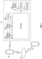
- FIG. 2 is a block diagram of example electronic components coupled to a display system 135 (e.g, a display of a processing device or other technique for presenting information).
- the illustrated electronic components include a controller 100 (e.g., hardware processor) for controlling the various devices in the eyewear 12; a wireless module (e.g., BluetoothTM) 102 for facilitating communication between the eyewear 12 and a client device (e.g., a personal computing device 50 such as a smartphone); a power circuit 104 (e.g., battery, filter, etc.) for powering eyewear 12; a memory 106 such as flash storage for storing data (e.g., images, video, image processing software, etc.); a selector 32; and one or more imagers 10 (two in the illustrated examples) for capturing one or more images (e.g., a picture or a video).
- the eyewear 12 and the personal computing device are illustrated as separate components, the functionality of the personal computing device may be incorporated into the eyewear enabling the personal computing
- the selector 32 may trigger (e.g., via a momentary push of a button) controller 100 of eyewear 12 to capture images/video.
- the selector may be used in a set up mode (e.g., entered by pressing and holding the selector 32 for a period of time, e.g., 3 seconds) and in an image capture mode (e.g., entered after a period of time with no contact, e.g., 5 seconds) to capture images.
- the selector 32 may be a physical button on the eyewear 12 that, when pressed, sends a user input signal to the controller 100.
- the controller 100 may interpret pressing the button for a predetermined period of time (e.g., three seconds) as a request to transition to a different mode of operation (e.g., in/out of a set-up mode of operation).
- the selector 32 may be a virtual button on the eyewear or another device.
- the selector may be a voice module that interprets voice commands or an eye detection module that detects where the focus of an eye is directed. Controller 100 may interpret signals from selector 32 as a trigger to cycle through illuminating LEDs 35 to select an intended recipient of the image(s).
- Wireless module 102 may couple with a client/personal computing device 50 such as a smartphone, tablet, phablet, laptop computer, desktop computer, networked appliance, access point device, or any other such device capable of connecting with wireless module 102.
- a client/personal computing device 50 such as a smartphone, tablet, phablet, laptop computer, desktop computer, networked appliance, access point device, or any other such device capable of connecting with wireless module 102.
- communication between the devices may facilitate transfer of software updates, images, videos, lighting schemes, and/or sound between eyewear 12 and the client device.
- personal computing device 50 may be in communication with one or more recipients (e.g., recipient personal computing device 51) via a network 53.
- the network 53 may be a cellular network, Wi-Fi, the Internet or the like that allows personal computing devices to transmit and receive an image(s), e.g., via text, email, instant messaging, etc.
- the computing devices 50/51 may each include a processor and a display. Suitable processors and displays, which may be configured to perform one more functions described herein, may be found in current generation personal computing devices and smartphones such as the iPhone 8 TM available from Apple Inc. of Cupertino, California and the Samsung Galaxy Note 9 TM available from the Samsung Group of Seoul, South Korea.
- the imager(s) 10 for capturing the images/video may include digital camera elements such as a charge-coupled device, a lens, or any other light capturing elements for capturing image data for conversion into an electrical signal(s).
- digital camera elements such as a charge-coupled device, a lens, or any other light capturing elements for capturing image data for conversion into an electrical signal(s).
- controller 100 controls the electronic components.
- controller 100 includes circuitry to receive signals from imager 10 and process those signals into a format suitable for storage in memory 106 (e.g., flash storage).
- Controller 100 powers on and boots to operate in a normal operational mode, or to enter a sleep mode.
- controller 100 includes a microprocessor integrated circuit (IC) customized for processing sensor data from imager 10, along with volatile memory used by the microprocessor to operate.
- the memory may store software code for execution by controller 100.
- Power circuit 104 may include a battery, power converter, and distribution circuitry (not shown).
- the battery may be a rechargeable battery such as lithium-ion or the like.
- Power converter and distribution circuitry may include electrical components for filtering and/or converting voltages for powering the various electronic components.
- FIG. 3A depicts a flow chart 300 illustrating example operation of eyewear (e.g., eyewear 12 of FIG. 1 ) and 3D scene rendering by a processing system (e.g., by a processor of eyewear 12 and/or the processor of a computing device remote to the eyewear.
- a processing system e.g., by a processor of eyewear 12 and/or the processor of a computing device remote to the eyewear.
- the steps of flow chart 300 are described with reference to eyewear 12 described herein.
- One of skill in the art will recognize other imager configurations not tied to eyewear for use in rendering 3D scenes. Additionally, it is to be understood that one or more of the steps may be omitted, performed by another component, or performed in a different order.
- a first 2D image of a scene object from a first viewpoint and a second 2D image of the scene object from a second viewpoint captures the first 2D image of the scene object from the first viewpoint and a second imager 10B of the eyewear 12 captures the second 2D image of the scene object from the second viewpoint.
- the captured images pass from the imagers 10A and 10B to a processing system for rendering of a 3D scene.
- the controller 100 of the eyewear 12 obtains the 2D images and renders the 3D scene from the obtained 2D images.
- the controller 100 receives the 2D images and transmits them to a processing system of a remote computing device 50/51 for rendering of the 3D scene.
- the processing system reconstructs the first and second 2D images into a 3D scene of the scene object.
- the processing system reconstructs the first and second 2D images into the 3D scene of the scene object.
- the processing system may apply a stereo-vision processing technique (i.e., to create a depth map) and geometric processing technique to create the 3D scene.
- the rendered 3D scene includes geometric features (e.g., vertices with x-axis, y-axis, and z-axis coordinates) along with image information (e.g., color information, depth information, and object information).
- the rendered 3D scene will also include connective as multi-angular faces, e.g., typically triangular faces or quadrangular faces, connecting the vertices to make up the textured surfaces of the scene objects.
- connective as multi-angular faces, e.g., typically triangular faces or quadrangular faces, connecting the vertices to make up the textured surfaces of the scene objects.
- Suitable stereo-vision processing techniques and geometric processing techniques will be understood by one of skill in the art from the description herein.
- FIG. 3B depicts a flowchart for example steps for reconstructing the first and second 2D images into a 3D scene of the scene object (step 320; FIG. 3A ).
- step 321 create a depth map from the first and second 2D images.
- the processing system may create a depth map by processing the first and second 2D images using a stereo-vision processing technique.
- step 322 create a 3D scene from the first and second 2D images.
- the processing system may create a 3D scene by geometrically processing the first and second 2D images along with the depth map created in step 321.
- the processing system may detect regions of the 3D scene with incomplete image information (e.g., missing color, depth, and/or object information). For example, the processing system may determine incomplete information by inspecting the shape of the faces making up the 3D scene and/or information such as confidence values associated with the vertices making up the faces.
- incomplete image information e.g., missing color, depth, and/or object information.
- the processing system may determine incomplete information by inspecting the shape of the faces making up the 3D scene and/or information such as confidence values associated with the vertices making up the faces.
- the processing system processes faces of the reconstructed 3D scene (step 323a; FIG. 3C ) to identify groups of contiguous faces exhibiting characteristics of incomplete information, e.g., very narrow faces and/or faces with one or more vertex having a low confidence value.
- the processing system may also, or alternatively, identity faces having a low confidence values (e.g., faces with at least one vertex having a confidence value below a threshold value) as regions with incomplete information (step 323c; FIG. 3C ).
- the confidence value of a vertex may be the confidence value of a corresponding pixel determined during stereo processing of the first and second 2D images to create the depth map (described above).
- the processing system may determine the replacement image information for the reconstructed detected regions and modify the 3D scene to include the replacement image information in the detected regions as they are being reconstructed. For example, the processing system may determine replacement image information for each of the detected regions by blending boundary information from the respective boundaries of each of the detected regions.
Landscapes
- Engineering & Computer Science (AREA)
- Physics & Mathematics (AREA)
- Theoretical Computer Science (AREA)
- General Physics & Mathematics (AREA)
- Computer Vision & Pattern Recognition (AREA)
- Computer Graphics (AREA)
- Geometry (AREA)
- Computing Systems (AREA)
- Software Systems (AREA)
- Processing Or Creating Images (AREA)
- Testing, Inspecting, Measuring Of Stereoscopic Televisions And Televisions (AREA)
Applications Claiming Priority (3)
| Application Number | Priority Date | Filing Date | Title |
|---|---|---|---|
| US201862737280P | 2018-09-27 | 2018-09-27 | |
| EP19864609.3A EP3857517B1 (de) | 2018-09-27 | 2019-09-04 | Inpainting dreidimensionaler szenen mittels stereoextraktion |
| PCT/US2019/049455 WO2020068383A1 (en) | 2018-09-27 | 2019-09-04 | Three dimensional scene inpainting using stereo extraction |
Related Parent Applications (1)
| Application Number | Title | Priority Date | Filing Date |
|---|---|---|---|
| EP19864609.3A Division EP3857517B1 (de) | 2018-09-27 | 2019-09-04 | Inpainting dreidimensionaler szenen mittels stereoextraktion |
Publications (2)
| Publication Number | Publication Date |
|---|---|
| EP4564304A2 true EP4564304A2 (de) | 2025-06-04 |
| EP4564304A3 EP4564304A3 (de) | 2025-08-20 |
Family
ID=69945945
Family Applications (2)
| Application Number | Title | Priority Date | Filing Date |
|---|---|---|---|
| EP25167877.7A Pending EP4564304A3 (de) | 2018-09-27 | 2019-09-04 | Inpainting dreidimensionaler szenen mittels stereoextraktion |
| EP19864609.3A Active EP3857517B1 (de) | 2018-09-27 | 2019-09-04 | Inpainting dreidimensionaler szenen mittels stereoextraktion |
Family Applications After (1)
| Application Number | Title | Priority Date | Filing Date |
|---|---|---|---|
| EP19864609.3A Active EP3857517B1 (de) | 2018-09-27 | 2019-09-04 | Inpainting dreidimensionaler szenen mittels stereoextraktion |
Country Status (5)
| Country | Link |
|---|---|
| US (4) | US11094108B2 (de) |
| EP (2) | EP4564304A3 (de) |
| KR (2) | KR102748283B1 (de) |
| CN (2) | CN120451009A (de) |
| WO (1) | WO2020068383A1 (de) |
Families Citing this family (3)
| Publication number | Priority date | Publication date | Assignee | Title |
|---|---|---|---|---|
| CN120451009A (zh) | 2018-09-27 | 2025-08-08 | 美国斯耐普公司 | 基于立体提取的三维场景修复 |
| US12277632B2 (en) | 2022-04-26 | 2025-04-15 | Snap Inc. | Augmented reality experiences with dual cameras |
| WO2026005506A1 (ko) * | 2024-06-26 | 2026-01-02 | 엘지전자 주식회사 | 무선 통신 시스템에서 통신을 수행하기 위한 방법 및 장치 |
Family Cites Families (35)
| Publication number | Priority date | Publication date | Assignee | Title |
|---|---|---|---|---|
| EP1587035A1 (de) * | 2004-04-14 | 2005-10-19 | Koninklijke Philips Electronics N.V. | Reduzierung von Geisterartefakten zur 2.5D Grafikdarstellung |
| US20090322671A1 (en) * | 2008-06-04 | 2009-12-31 | Cybernet Systems Corporation | Touch screen augmented reality system and method |
| US8933925B2 (en) * | 2009-06-15 | 2015-01-13 | Microsoft Corporation | Piecewise planar reconstruction of three-dimensional scenes |
| US8711204B2 (en) * | 2009-11-11 | 2014-04-29 | Disney Enterprises, Inc. | Stereoscopic editing for video production, post-production and display adaptation |
| US9406132B2 (en) * | 2010-07-16 | 2016-08-02 | Qualcomm Incorporated | Vision-based quality metric for three dimensional video |
| EP2596475B1 (de) * | 2010-07-19 | 2019-01-16 | Fraunhofer-Gesellschaft zur Förderung der angewandten Forschung e.V. | Ausfüllen von aufgedeckten bereichen in einer virtuellen ansicht |
| US8718393B2 (en) * | 2010-07-28 | 2014-05-06 | Shenzhen Institutes Of Advanced Technology Chinese Academy Of Sciences | Method for reconstruction of urban scenes |
| US9582928B2 (en) | 2011-01-13 | 2017-02-28 | Samsung Electronics Co., Ltd. | Multi-view rendering apparatus and method using background pixel expansion and background-first patch matching |
| US8655055B2 (en) * | 2011-05-04 | 2014-02-18 | Texas Instruments Incorporated | Method, system and computer program product for converting a 2D image into a 3D image |
| KR20140041489A (ko) * | 2011-05-19 | 2014-04-04 | 톰슨 라이센싱 | 스테레오스코픽 이미지의 동시적인 스테레오스코픽 및 모노스코픽 디스플레이를 가능하게 하기 위한 스테레오스코픽 이미지의 자동 컨버전 |
| TR201819457T4 (tr) * | 2011-06-22 | 2019-01-21 | Koninklijke Philips Nv | Bir sunum ekranı için bir sinyal oluşturmak üzere yöntem ve cihaz. |
| WO2013050184A1 (en) * | 2011-10-04 | 2013-04-11 | Telefonaktiebolaget L M Ericsson (Publ) | Objective 3d video quality assessment model |
| US20140285623A1 (en) * | 2011-10-10 | 2014-09-25 | Koninklijke Philips N.V. | Depth map processing |
| US10848731B2 (en) * | 2012-02-24 | 2020-11-24 | Matterport, Inc. | Capturing and aligning panoramic image and depth data |
| US20140098100A1 (en) * | 2012-10-05 | 2014-04-10 | Qualcomm Incorporated | Multiview synthesis and processing systems and methods |
| ITTO20121073A1 (it) * | 2012-12-13 | 2014-06-14 | Rai Radiotelevisione Italiana | Apparato e metodo per la generazione e la ricostruzione di un flusso video |
| US9761037B2 (en) * | 2013-10-17 | 2017-09-12 | Nvidia Corporation | Graphics processing subsystem and method for updating voxel representation of a scene |
| KR20160118363A (ko) * | 2014-03-20 | 2016-10-11 | 니폰 덴신 덴와 가부시끼가이샤 | 화상 부호화 장치 및 방법, 화상 복호 장치 및 방법, 및 이들의 프로그램 |
| US9311565B2 (en) * | 2014-06-16 | 2016-04-12 | Sony Corporation | 3D scanning with depth cameras using mesh sculpting |
| JP6407423B2 (ja) * | 2014-06-26 | 2018-10-17 | ホアウェイ・テクノロジーズ・カンパニー・リミテッド | 高効率映像符号化においてデプスベースのブロック分割を提供するための方法および装置 |
| US20160073094A1 (en) | 2014-09-05 | 2016-03-10 | Microsoft Corporation | Depth map enhancement |
| WO2016044296A1 (en) * | 2014-09-15 | 2016-03-24 | Second Sight Medical Products, Inc. | Method and system for detecting obstacles for a visual prosthesis |
| US20160232705A1 (en) * | 2015-02-10 | 2016-08-11 | Mitsubishi Electric Research Laboratories, Inc. | Method for 3D Scene Reconstruction with Cross-Constrained Line Matching |
| KR20170055930A (ko) * | 2015-11-12 | 2017-05-22 | 삼성전자주식회사 | 3d 디스플레이 시스템에서 입체 이미지 디스플레이 방법 및 장치 |
| CN105704476B (zh) * | 2016-01-14 | 2018-03-20 | 东南大学 | 一种基于边缘修复的虚拟视点图像频域快速获取方法 |
| US9851585B2 (en) * | 2016-02-29 | 2017-12-26 | Snap Inc. | Heat sink configuration for wearable electronic device |
| US10302446B2 (en) * | 2016-06-12 | 2019-05-28 | Apple Inc. | Context driven navigation presentation |
| US10573018B2 (en) * | 2016-07-13 | 2020-02-25 | Intel Corporation | Three dimensional scene reconstruction based on contextual analysis |
| US10321114B2 (en) * | 2016-08-04 | 2019-06-11 | Google Llc | Testing 3D imaging systems |
| US10176589B2 (en) * | 2017-01-31 | 2019-01-08 | Mitsubishi Electric Research Labroatories, Inc. | Method and system for completing point clouds using planar segments |
| GB201703129D0 (en) * | 2017-02-27 | 2017-04-12 | Metail Ltd | Quibbler |
| US20180300937A1 (en) * | 2017-04-13 | 2018-10-18 | National Taiwan University | System and a method of restoring an occluded background region |
| GB2562037A (en) * | 2017-04-25 | 2018-11-07 | Nokia Technologies Oy | Three-dimensional scene reconstruction |
| CN120451009A (zh) | 2018-09-27 | 2025-08-08 | 美国斯耐普公司 | 基于立体提取的三维场景修复 |
| US10930054B2 (en) * | 2019-06-18 | 2021-02-23 | Intel Corporation | Method and system of robust virtual view generation between camera views |
-
2019
- 2019-09-04 CN CN202510522392.6A patent/CN120451009A/zh active Pending
- 2019-09-04 WO PCT/US2019/049455 patent/WO2020068383A1/en not_active Ceased
- 2019-09-04 EP EP25167877.7A patent/EP4564304A3/de active Pending
- 2019-09-04 EP EP19864609.3A patent/EP3857517B1/de active Active
- 2019-09-04 US US16/559,852 patent/US11094108B2/en active Active
- 2019-09-04 CN CN201980062166.7A patent/CN112805753B/zh active Active
- 2019-09-04 KR KR1020217012080A patent/KR102748283B1/ko active Active
- 2019-09-04 KR KR1020247042633A patent/KR20250005536A/ko active Pending
-
2021
- 2021-08-04 US US17/394,164 patent/US11670040B2/en active Active
-
2023
- 2023-05-02 US US18/142,217 patent/US12223588B2/en active Active
-
2025
- 2025-01-15 US US19/022,128 patent/US20250157138A1/en active Pending
Also Published As
| Publication number | Publication date |
|---|---|
| CN120451009A (zh) | 2025-08-08 |
| CN112805753B (zh) | 2025-04-18 |
| KR102748283B1 (ko) | 2024-12-27 |
| US12223588B2 (en) | 2025-02-11 |
| US20210366182A1 (en) | 2021-11-25 |
| WO2020068383A1 (en) | 2020-04-02 |
| US20230281916A1 (en) | 2023-09-07 |
| US11094108B2 (en) | 2021-08-17 |
| US11670040B2 (en) | 2023-06-06 |
| KR20210050582A (ko) | 2021-05-07 |
| US20250157138A1 (en) | 2025-05-15 |
| EP3857517A4 (de) | 2022-06-29 |
| US20200105051A1 (en) | 2020-04-02 |
| EP3857517B1 (de) | 2025-04-02 |
| EP4564304A3 (de) | 2025-08-20 |
| KR20250005536A (ko) | 2025-01-09 |
| CN112805753A (zh) | 2021-05-14 |
| EP3857517A1 (de) | 2021-08-04 |
Similar Documents
| Publication | Publication Date | Title |
|---|---|---|
| US12223588B2 (en) | Three dimensional scene inpainting using stereo extraction | |
| US11575872B2 (en) | Flexible eyewear device with dual cameras for generating stereoscopic images | |
| EP3005286B1 (de) | Bildneufokussierung | |
| CN106060520B (zh) | 一种显示模式切换方法及其装置、智能终端 | |
| EP2852161A1 (de) | Verfahren und vorrichtung zur durchführung einer stereobildgebung | |
| WO2012153447A1 (ja) | 画像処理装置、映像処理方法、プログラム、集積回路 | |
| CN106031154A (zh) | 处理图像的方法和用于其的电子设备 | |
| CN104599317A (zh) | 一种实现3d扫描建模功能的移动终端及方法 | |
| CN103488040A (zh) | 立体全景影像合成方法及其相关的立体摄影机 | |
| CN105791793A (zh) | 图像处理方法及其电子装置 | |
| CN104813230A (zh) | 使用单个相机捕捉三维图像的方法和系统 | |
| WO2013148963A1 (en) | Intelligent depth control | |
| CN106331685A (zh) | 一种3d全景图像获取方法和装置 | |
| CN103220458B (zh) | 一种立体摄像装置和立体摄像方法 | |
| KR101379879B1 (ko) | 2차원 이미지 콘텐츠를 3차원 이미지 콘텐츠로 변환하는 시스템 및 상기 2차원 이미지 콘텐츠를 3차원 이미지 콘텐츠로 변환하는 방법 |
Legal Events
| Date | Code | Title | Description |
|---|---|---|---|
| PUAI | Public reference made under article 153(3) epc to a published international application that has entered the european phase |
Free format text: ORIGINAL CODE: 0009012 |
|
| STAA | Information on the status of an ep patent application or granted ep patent |
Free format text: STATUS: THE APPLICATION HAS BEEN PUBLISHED |
|
| AC | Divisional application: reference to earlier application |
Ref document number: 3857517 Country of ref document: EP Kind code of ref document: P |
|
| AK | Designated contracting states |
Kind code of ref document: A2 Designated state(s): AL AT BE BG CH CY CZ DE DK EE ES FI FR GB GR HR HU IE IS IT LI LT LU LV MC MK MT NL NO PL PT RO RS SE SI SK SM TR |
|
| REG | Reference to a national code |
Ref country code: DE Ref legal event code: R079 Free format text: PREVIOUS MAIN CLASS: G06T0017000000 Ipc: G06T0007593000 |
|
| PUAL | Search report despatched |
Free format text: ORIGINAL CODE: 0009013 |
|
| AK | Designated contracting states |
Kind code of ref document: A3 Designated state(s): AL AT BE BG CH CY CZ DE DK EE ES FI FR GB GR HR HU IE IS IT LI LT LU LV MC MK MT NL NO PL PT RO RS SE SI SK SM TR |
|
| RIC1 | Information provided on ipc code assigned before grant |
Ipc: G06T 7/593 20170101AFI20250716BHEP Ipc: G06T 17/00 20060101ALI20250716BHEP Ipc: G06T 15/20 20110101ALI20250716BHEP |
|
| STAA | Information on the status of an ep patent application or granted ep patent |
Free format text: STATUS: REQUEST FOR EXAMINATION WAS MADE |
|
| 17P | Request for examination filed |
Effective date: 20260213 |