EP4564276A1 - Carbon management system and information processing device - Google Patents
Carbon management system and information processing device Download PDFInfo
- Publication number
- EP4564276A1 EP4564276A1 EP22953138.9A EP22953138A EP4564276A1 EP 4564276 A1 EP4564276 A1 EP 4564276A1 EP 22953138 A EP22953138 A EP 22953138A EP 4564276 A1 EP4564276 A1 EP 4564276A1
- Authority
- EP
- European Patent Office
- Prior art keywords
- facility
- amount
- emission
- utilization
- exhaust gas
- Prior art date
- Legal status (The legal status is an assumption and is not a legal conclusion. Google has not performed a legal analysis and makes no representation as to the accuracy of the status listed.)
- Pending
Links
Images




Classifications
-
- G—PHYSICS
- G06—COMPUTING OR CALCULATING; COUNTING
- G06Q—INFORMATION AND COMMUNICATION TECHNOLOGY [ICT] SPECIALLY ADAPTED FOR ADMINISTRATIVE, COMMERCIAL, FINANCIAL, MANAGERIAL OR SUPERVISORY PURPOSES; SYSTEMS OR METHODS SPECIALLY ADAPTED FOR ADMINISTRATIVE, COMMERCIAL, FINANCIAL, MANAGERIAL OR SUPERVISORY PURPOSES, NOT OTHERWISE PROVIDED FOR
- G06Q10/00—Administration; Management
- G06Q10/06—Resources, workflows, human or project management; Enterprise or organisation planning; Enterprise or organisation modelling
- G06Q10/063—Operations research, analysis or management
-
- B—PERFORMING OPERATIONS; TRANSPORTING
- B01—PHYSICAL OR CHEMICAL PROCESSES OR APPARATUS IN GENERAL
- B01D—SEPARATION
- B01D53/00—Separation of gases or vapours; Recovering vapours of volatile solvents from gases; Chemical or biological purification of waste gases, e.g. engine exhaust gases, smoke, fumes, flue gases, aerosols
- B01D53/14—Separation of gases or vapours; Recovering vapours of volatile solvents from gases; Chemical or biological purification of waste gases, e.g. engine exhaust gases, smoke, fumes, flue gases, aerosols by absorption
- B01D53/1456—Removing acid components
- B01D53/1475—Removing carbon dioxide
-
- G—PHYSICS
- G06—COMPUTING OR CALCULATING; COUNTING
- G06Q—INFORMATION AND COMMUNICATION TECHNOLOGY [ICT] SPECIALLY ADAPTED FOR ADMINISTRATIVE, COMMERCIAL, FINANCIAL, MANAGERIAL OR SUPERVISORY PURPOSES; SYSTEMS OR METHODS SPECIALLY ADAPTED FOR ADMINISTRATIVE, COMMERCIAL, FINANCIAL, MANAGERIAL OR SUPERVISORY PURPOSES, NOT OTHERWISE PROVIDED FOR
- G06Q10/00—Administration; Management
- G06Q10/04—Forecasting or optimisation specially adapted for administrative or management purposes, e.g. linear programming or "cutting stock problem"
-
- G—PHYSICS
- G06—COMPUTING OR CALCULATING; COUNTING
- G06Q—INFORMATION AND COMMUNICATION TECHNOLOGY [ICT] SPECIALLY ADAPTED FOR ADMINISTRATIVE, COMMERCIAL, FINANCIAL, MANAGERIAL OR SUPERVISORY PURPOSES; SYSTEMS OR METHODS SPECIALLY ADAPTED FOR ADMINISTRATIVE, COMMERCIAL, FINANCIAL, MANAGERIAL OR SUPERVISORY PURPOSES, NOT OTHERWISE PROVIDED FOR
- G06Q10/00—Administration; Management
- G06Q10/08—Logistics, e.g. warehousing, loading or distribution; Inventory or stock management
-
- G—PHYSICS
- G06—COMPUTING OR CALCULATING; COUNTING
- G06Q—INFORMATION AND COMMUNICATION TECHNOLOGY [ICT] SPECIALLY ADAPTED FOR ADMINISTRATIVE, COMMERCIAL, FINANCIAL, MANAGERIAL OR SUPERVISORY PURPOSES; SYSTEMS OR METHODS SPECIALLY ADAPTED FOR ADMINISTRATIVE, COMMERCIAL, FINANCIAL, MANAGERIAL OR SUPERVISORY PURPOSES, NOT OTHERWISE PROVIDED FOR
- G06Q10/00—Administration; Management
- G06Q10/30—Administration of product recycling or disposal
-
- G—PHYSICS
- G06—COMPUTING OR CALCULATING; COUNTING
- G06Q—INFORMATION AND COMMUNICATION TECHNOLOGY [ICT] SPECIALLY ADAPTED FOR ADMINISTRATIVE, COMMERCIAL, FINANCIAL, MANAGERIAL OR SUPERVISORY PURPOSES; SYSTEMS OR METHODS SPECIALLY ADAPTED FOR ADMINISTRATIVE, COMMERCIAL, FINANCIAL, MANAGERIAL OR SUPERVISORY PURPOSES, NOT OTHERWISE PROVIDED FOR
- G06Q40/00—Finance; Insurance; Tax strategies; Processing of corporate or income taxes
- G06Q40/04—Trading; Exchange, e.g. stocks, commodities, derivatives or currency exchange
-
- G—PHYSICS
- G06—COMPUTING OR CALCULATING; COUNTING
- G06Q—INFORMATION AND COMMUNICATION TECHNOLOGY [ICT] SPECIALLY ADAPTED FOR ADMINISTRATIVE, COMMERCIAL, FINANCIAL, MANAGERIAL OR SUPERVISORY PURPOSES; SYSTEMS OR METHODS SPECIALLY ADAPTED FOR ADMINISTRATIVE, COMMERCIAL, FINANCIAL, MANAGERIAL OR SUPERVISORY PURPOSES, NOT OTHERWISE PROVIDED FOR
- G06Q50/00—Information and communication technology [ICT] specially adapted for implementation of business processes of specific business sectors, e.g. utilities or tourism
- G06Q50/06—Energy or water supply
-
- B—PERFORMING OPERATIONS; TRANSPORTING
- B01—PHYSICAL OR CHEMICAL PROCESSES OR APPARATUS IN GENERAL
- B01D—SEPARATION
- B01D2257/00—Components to be removed
- B01D2257/50—Carbon oxides
- B01D2257/504—Carbon dioxide
-
- B—PERFORMING OPERATIONS; TRANSPORTING
- B01—PHYSICAL OR CHEMICAL PROCESSES OR APPARATUS IN GENERAL
- B01D—SEPARATION
- B01D53/00—Separation of gases or vapours; Recovering vapours of volatile solvents from gases; Chemical or biological purification of waste gases, e.g. engine exhaust gases, smoke, fumes, flue gases, aerosols
- B01D53/34—Chemical or biological purification of waste gases
- B01D53/46—Removing components of defined structure
- B01D53/62—Carbon oxides
-
- F—MECHANICAL ENGINEERING; LIGHTING; HEATING; WEAPONS; BLASTING
- F23—COMBUSTION APPARATUS; COMBUSTION PROCESSES
- F23J—REMOVAL OR TREATMENT OF COMBUSTION PRODUCTS OR COMBUSTION RESIDUES; FLUES
- F23J2215/00—Preventing emissions
- F23J2215/50—Carbon dioxide
Definitions
- PTL 1 describes, in this concept, that a CO 2 emitter, a CO 2 user, a CO 2 pipe connecting them, and a carbon recycling device are provided, a scheduled amount of CO 2 used for carbon recycling is notified to a constituent business operator of a complex, and CO 2 is supplied from a carbon dioxide supplier on the basis of the scheduled CO 2 usage amount.
- CO 2 is generated as a by-product of the main business of the CO 2 emitter, and the emission amount of the exhaust gas containing CO 2 is not easily changed according to the use of the CO 2 user.
- an object of the present invention is to provide a carbon management system or the like that recovers CO 2 from exhaust gas from a factory group and supplies the CO 2 to a plurality of CO 2 users.
- a carbon management system includes: a plurality of emission facilities which emit an exhaust gas containing CO 2 ; a processing facility which separates a CO 2 gas from the exhaust gas emitted from the emission facility; a plurality of utilization facilities which use the CO 2 gas separated in the processing facility; a first conduit which guides, to the processing facility, the exhaust gas emitted from the plurality of emission facilities; a second conduit which guides the CO 2 gas separated in the processing facility to the plurality of utilization facilities; a storage facility which is connected to the first conduit or the second conduit and stores the CO 2 gas; and an information processing device which sets operating conditions of the processing facility and the storage facility.
- the present invention it is possible to provide a carbon management system or the like that recovers CO 2 from an exhaust gas from a factory group and supplies the CO 2 to a plurality of CO 2 users.
- FIG. 1 is a configuration diagram of a carbon management system 100 according to a first embodiment.
- the carbon management system 100 is a system that manages distribution of CO 2 (carbon dioxide) supplied from CO 2 emission facilities 21 to 23 (emission facility) to CO 2 utilization facilities 31 to 33 (utilization facility) via a CO 2 distribution grid G1.
- the carbon management system 100 includes the CO 2 emission facilities 21 to 23, a processing facility 11, a storage facility 12, a pressure reduction valve 13, the CO 2 utilization facilities 31 to 33, and an information processing device 41.
- the carbon management system 100 includes conduits 5a to 5d as "first conduits" for guiding, to the processing facility 11, the exhaust gas emitted from the CO 2 emission facilities 21 to 23.
- the carbon management system 100 includes conduits 5e to 5i as "second conduits" for guiding the CO 2 gas separated in the processing facility 11 to the plurality of CO 2 utilization facilities 31 to 33.
- the CO 2 emission facilities 21 to 23 illustrated in FIG. 1 are facilities that emit an exhaust gas containing CO 2 .
- Examples of such a CO 2 emission facilities 21 to 23 include a factory and a power plant.
- the conduits 5a to 5c are connected to the CO 2 emission facilities 21 to 23 in a one-to-one correspondence. Then, the CO 2 gas flowing through the conduits 5a to 5c is merged in the conduit 5d, and the merged CO 2 gas is guided to the processing facility 11 through the conduit 5d.
- the processing facility 11 is a facility that separates (recovers) a CO 2 gas from the exhaust gas emitted from the CO 2 emission facilities 21 to 23.
- a method for separating a CO 2 gas for example, there is a chemical absorption method in which an alkaline CO 2 absorbent and an exhaust gas are brought into contact with each other to absorb CO 2 in the exhaust gas into the CO 2 absorbent.
- a physical adsorption method using an adsorbent using van der Waals force a chemical adsorption method in which an alkaline CO 2 adsorbent (solid) and an exhaust gas are brought into contact with each other to adsorb CO 2 in the exhaust gas to the CO 2 adsorbent, and the like. Note that a process of concentrating a CO 2 gas is also included in the separation of a CO 2 gas.
- the storage facility 12 is a facility that stores a CO 2 gas. As such a storage facility 12, for example, a tank is used. Then, a CO 2 gas is guided from the processing facility 11 to the storage facility 12 via the conduit 5e. The CO 2 gas temporarily stored in the storage facility 12 is supplied to the CO 2 utilization facilities 31 and 32 via the conduits 5f to 5i (second conduits). That is, the storage facility 12 is connected to the "second conduit" described above. More specifically, the CO 2 gas flowing from the storage facility 12 into the conduit 5f is divided into the conduits 5g to 5i, and is further supplied to the CO 2 utilization facilities 31 to 33. Note that the conduits 5g to 5i are connected to the CO 2 utilization facilities 31 to 33 in a one-to-one correspondence.
- the CO 2 utilization facilities 31 to 33 are facilities utilizing the CO 2 gas separated by the processing facility 11, and is provided in an industrial accumulation place or the like. Since the CO 2 gas having a certain concentration or higher is used in the CO 2 utilization facilities 31 to 33, basically, the CO 2 gas is supplied to the CO 2 emission facilities 21 to 23 via the processing facility 11. However, when the CO 2 concentration of the emission gas is sufficiently high, the CO 2 utilization facilities 31 to 33 and the CO 2 emission facilities 21 to 23 may be connected without the processing facility 11. In addition, in FIG. 1 , three CO 2 emission facilities 21 to 23 and three CO 2 utilization facilities 31 to 33 are illustrated, but the number of CO 2 emission facilities or CO 2 utilization facilities is not limited thereto, and may be one or more.
- the CO 2 distribution grid G1 illustrated in FIG. 1 is a pipeline network through which an exhaust gas containing CO 2 and a CO 2 gas flow. Note that portions where the exhaust gas containing CO 2 enters the CO 2 distribution grid G1 are referred to as inflow points A1 to A3. In addition, portions where the CO 2 gas flows out from the CO 2 distribution grid G1 are referred to as outflow points B1 to B3.
- the inflow point A1 exists in the conduit 5a connected to the CO 2 emission facility 21.
- the inflow point A2 exists in the conduit 5b
- the inflow point A3 exists in the conduit 5c.
- the outflow point B1 exists in the conduit 5g connected to the CO 2 utilization facility 31.
- the outflow point B2 exists in the conduit 5h, and the outflow point B3 exists in the conduit 5i.
- conduits 5a, 5b, and 5c on the inflow side and the conduits 5g, 5h, and 5i on the outflow side are included in the CO 2 distribution grid G1, but these conduits may not be included in the CO 2 distribution grid G1.
- the pressure reduction valve 13 is a valve that adjusts a flow rate of CO 2 gas (or exhaust gas) flowing in the CO 2 distribution grid G1.
- a pressure reduction valve 13 is provided in the conduit 5i (second conduit) connected to the CO 2 utilization facility 33. Note that the flow rate of the CO 2 gas flowing through the conduit 5i decreases as the opening degree of the pressure reduction valve 13 decreases. Therefore, by adjusting the opening degree of the pressure reduction valve 13, the flow rate ratio of CO 2 in the conduits 5 g, 5h, and 5i is also adjusted.
- a measurement/communication device 6a is provided near the inflow point A1 in the conduit 5a.
- the measurement/communication device 6a measures the flow rate, the pressure, and the CO 2 concentration of the exhaust gas flowing from the CO 2 emission facility 21 to the CO 2 distribution grid G1 via the conduit 5a, and transmits the measurement result to a CO 2 distribution grid management information system 40.
- a measurement/communication device 6b is provided in the conduit 5b, and a measurement/communication device 6c is provided in another conduit 5c.
- the information processing device 41 of the CO 2 distribution grid management information system 40 may calculate the flow rate, the pressure, and the CO 2 concentration of the exhaust gas on the basis of the application, performance, and operation status of the CO 2 emission facility 21.
- a measurement/communication device 6g is provided near the outflow point B1 of the conduit 5g.
- the measurement/communication device 6g measures the flow rate, the pressure, and the CO 2 concentration of the CO 2 gas supplied from the CO 2 distribution grid G1 to the CO 2 utilization facility 31, and transmits the measurement result to the CO 2 distribution grid management information system 40.
- a measurement/communication device 6h is provided in the conduit 5h
- a measurement/communication device 6i is provided in another conduit 5i.
- the information processing device 41 of the CO 2 distribution grid management information system 40 may calculate the flow rate, the pressure, and the CO 2 concentration of the CO 2 gas used in the CO 2 utilization facility 31 on the basis of the application, performance, and operation status of the CO 2 utilization facility 31.
- a measurement/communication device 6d is provided in the processing facility 11, and a measurement/communication device 6e is also provided in the storage facility 12. Note that instead of the measurement/communication devices 6d and 6e, a measurement/communication device (not illustrated) may be provided in each of the conduits 5d, 5e, and 5f. A measurement/communication device 6f is also provided near the pressure reduction valve 13 in the conduit 5i. The measurement results of these measurement/communication devices 6d, 6e, and 6f are also transmitted to the CO 2 distribution grid management information system 40.
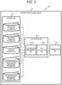
- FIG. 2 is a functional block diagram illustrating a configuration of the information processing device 41.
- the information processing device 41 includes a communication unit 411 (information acquisition unit), a storage unit 412, and a calculation unit 413.
- the communication unit 411 acquires information on the CO 2 emission facilities 21 to 23 (see FIG. 1 ), the processing facility 11 (see FIG. 1 ), the CO 2 utilization facilities 31 to 33 (see FIG. 1 ), and the like.
- the communication unit 411 acquires the emission amount (flow rate/CO 2 concentration) of the exhaust gas of each of the CO 2 emission facilities 21 to 23.
- the present embodiment discloses an example in which the information acquisition unit is the communication unit 411, but the information acquisition unit may be an input device that acquires information by input from a user.
- the storage unit 412 stores the information acquired by the communication unit 411 (information acquisition unit) . That is, the storage unit 412 stores grid/device attribute information 412a, grid/device operation information 412b, contract information 412c, CO 2 emission amount/usage amount management information 412d, and CO 2 emission right management information 412e.
- the grid/device attribute information 412a includes not only information indicating design specifications of the CO 2 emission facilities 21 to 23 (see FIG. 1 ) and the CO 2 utilization facilities 31 to 33 (see FIG. 1 ) but also information indicating design specifications, applications, and performance of each facility in the CO 2 distribution grid G1 (see FIG. 1 ).
- the grid/device operation information 412b is information indicating the operation status of each facility included in the CO 2 distribution grid G1 (see FIG. 1 ) in addition to the CO 2 emission facilities 21 to 23 (see FIG. 1 ) and the CO 2 utilization facilities 31 to 33 (see FIG. 1 ).
- the contract information 412c is information indicating a contract content such as a supply amount of CO 2 gas (supply amount per predetermined period) to the CO 2 utilization facilities 31 to 33 (see FIG. 1 ).
- the CO 2 emission amount/usage amount management information 412d is information including the amount of the exhaust gas emitted from the CO 2 emission facilities 21 to 23 (see FIG. 1 ) and the actual value of the amount of CO 2 gas supplied to the CO 2 utilization facilities 31 to 33 (see FIG. 1 ).
- the CO 2 emission right management information 412e is information for specifying a CO 2 emission right regarding the release of the CO 2 gas to the atmosphere.
- the CO 2 emission right is usually purchased from a CO 2 emission right transaction market 70 (see FIG. 1 ).
- the calculation unit 413 illustrated in FIG. 2 sets the operating conditions of the processing facility 11 (see FIG. 1 ), the storage facility 12 (see FIG. 1 ), and the pressure reduction valve 13 (see FIG. 1 ).
- the calculation unit 413 includes a CO 2 emission management unit 413a and a grid calculation unit 413b.
- the CO 2 emission management unit 413a calculates the total emission amount of the exhaust gas and the like.
- the grid calculation unit 413b sets the operating condition of each facility included in the CO 2 distribution grid G1 (see FIG. 1 ) on the basis of the total emission amount of the exhaust gas and the like. Note that details of the processing of the calculation unit 413 will be described later.
- FIG. 3 is a functional block diagram illustrating a configuration of an emission-side information system 80.
- the emission-side information system 80 illustrated in FIG. 3 is a system that monitors, controls, and manages the CO 2 emission facility 21, and is connected to the CO 2 emission facility 21 via a communication line and can communicate with the information processing device 41 (see FIG. 1 ).
- the emission-side information system 80 includes a storage device 81, a calculation device 82, and a communication device 83.
- the storage device 81 stores operation plan information 81a and CO 2 emission amount information 81b.
- the operation plan information 81a is information indicating the expectation of the future (for example, several hours or several days) operation of the CO 2 emission facility 21.
- the CO 2 emission amount information 81b is information indicating the expectation of the future CO 2 emission amount of the CO 2 emission facility 21.
- the calculation device 82 performs processing related to monitoring, control, and management of the CO 2 emission facility 21.
- the communication device 83 transmits the calculation result of the calculation device 82 to the CO 2 emission facility 21 and the information processing device 41 (not illustrated). Note that each of the other CO 2 emission facilities 22 and 23 (see FIG. 1 ) is also provided with an emission-side information system (not illustrated).
- FIG. 4 is a functional block diagram illustrating a configuration of a utilization-side information system 90.
- the utilization-side information system 90 illustrated in FIG. 4 is a system that monitors, controls, and manages the CO 2 utilization facility 31, and is connected to the CO 2 utilization facility 31 via a communication line and can communicate with the information processing device 41 (see FIG. 1 ).
- the utilization-side information system 90 includes a storage device 91, a calculation device 92, and a communication device 93.
- the storage device 91 stores operation plan information 91a and CO 2 usage amount information 91b.
- the operation plan information 91a is information indicating the expectation of the future (for example, several hours or several days) operation of the CO 2 utilization facility 31.
- the CO 2 usage amount information 91b is information indicating an expectation of the future CO 2 usage amount of the CO 2 utilization facility 31.
- the calculation device 92 performs processing related to monitoring, control, and management of the CO 2 utilization facility 31.
- the communication device 93 transmits the calculation result of the calculation device 92 to the CO 2 utilization facility 31 and the information processing device 41 (not illustrated). Note that each of the other CO 2 utilization facilities 32 and 33 (see FIG. 1 ) is also provided with a utilization-side information system (not illustrated).
- FIG. 5 is a flowchart illustrating processing executed by the information processing device (see also FIG. 2 as appropriate).
- step S101 the information processing device 41 causes the calculation unit 413 to calculate the total emission amount of the exhaust gas. That is, the calculation unit 413 calculates the total emission amount of the exhaust gas of the entire carbon management system 100 on the basis of the amount of the exhaust gas emitted by each of the CO 2 emission facilities 21 to 23 (see FIG. 1 ) acquired by the communication unit 411 (information acquisition unit). Note that the amount of the exhaust gas emitted by each of the CO 2 emission facilities 21 to 23 (see FIG. 1 ) is calculated on the basis of the design specifications of the CO 2 emission facilities 21 to 23 and the operation status of the CO 2 emission facilities 21 to 23 acquired by the communication unit 411 (information acquisition unit).
- the information processing device 41 causes the calculation unit 413 to calculate the operating condition of each facility. That is, the calculation unit 413 calculates the operating conditions of the processing facility 11, the storage facility 12, and the pressure reduction valve 13 on the basis of the total emission amount of the exhaust gas. Specifically, the calculation unit 413 calculates the total emission amount of the exhaust gas delivered from the CO 2 emission facilities 21 to 23 (see FIG. 1 ) to the processing facility 11 (see FIG. 1 ) and the average value of the CO 2 concentration, on the basis of the emission amount (flow rate/CO 2 concentration) of the exhaust gas collected via the communication unit 411, and calculates the operating conditions of the processing facility 11, the storage facility 12, and the pressure reduction valve 13 on the basis of these respective values.
- the calculation unit 413 may perform the following processing in step S102. That is, the calculation unit 413 may calculate the operating conditions of the processing facility 11, the storage facility 12, and the pressure reduction valve 13 on the basis of the amount of the exhaust gas emitted by the CO 2 emission facilities 21 to 23 (see FIG. 1 ) and the amount of the CO 2 gas used by the CO 2 utilization facilities 31 to 33 (see FIG. 1 ). Note that the amount of CO 2 gas used by the CO 2 utilization facilities 31 to 33 is calculated on the basis of the design specification of the CO 2 utilization facilities 31 to 33 and the operation status of the CO 2 utilization facilities 31 to 33 acquired by the communication unit 411 (information acquisition unit).
- the calculation unit 413 may perform the following processing in step S102. That is, the calculation unit 413 may determine the processing amount of the processing facility 11 (see FIG. 1 ) and the temporary storage amount in the storage facility 12 (see FIG. 1 ) on the basis of the amount of the exhaust gas emitted by the CO 2 emission facilities 21 to 23 (see FIG. 1 ), the amount of CO 2 gas used by the CO 2 utilization facilities 31 to 33 (see FIG. 1 ), and the design value of the processing amount (processing amount per unit time) of the processing facility 11 and the design value of the storage amount of the storage facility 12 which are stored in advance in the storage unit 412. In this case, the calculation unit 413 calculates the operating conditions of the processing facility 11, the storage facility 12, and the pressure reduction valve 13 so as to satisfy the determined processing amount and storage amount.
- the calculation unit 413 may perform the following processing in step S102. That is, the calculation unit 413 calculates the total emission amount of the exhaust gas delivered from all the CO 2 emission facilities 21 to 23 (see FIG. 1 ) to the processing facility 11 and the average value of the CO 2 concentration on the basis of the emission amount (flow rate and CO 2 concentration) of the exhaust gas collected via the communication unit 411, and calculates the operating condition of the processing facility 11. Then, the calculation unit 413 calculates the operating conditions of the storage facility 12 and the pressure reduction valve 13 on the basis of the total emission amount of the exhaust gas, the average value of the CO 2 concentration, and the amount (flow rate/CO 2 concentration) of the CO 2 gas used by the CO 2 utilization facilities 31 to 33 (see FIG. 1 ). Also by such a method, the amount of CO 2 gas supplied to the CO 2 utilization facilities 31 to 33 can be appropriately adjusted.
- the operating condition calculated by the calculation unit 413 may deviate from a predetermined range of the upper limit value and the lower limit value. For example, in a case where the operating conditions of the processing facility 11, the storage facility 12, and the pressure reduction valve 13 are not executable, the calculation unit 413 calculates the amount of the exhaust gas emitted by the CO 2 emission facilities 21 to 23 (see FIG.
- the calculation result of the calculation unit 413 is transmitted to the emission-side information system 80 (see FIG. 3 ) or the utilization-side information system 90 (see FIG. 4 ) via the communication unit 411.
- the calculation unit 413 preferably sets the operating conditions of the processing facility 11 and the storage facility 12 so as to stabilize the facility load and the operation load of the processing facility 11.
- the emission-side information system 80 determines whether or not to accept the request to change the emission amount on the basis of the operation plan information 81a of the CO 2 emission facility 21. Then, the emission-side information system 80 transmits a response (acceptance or rejection) to the request to change the emission amount to the information processing device 41.
- the utilization-side information system 90 determines whether or not to accept the request to change the usage amount on the basis of the operation plan information 91a of the CO 2 utilization facility 31. Then, the utilization-side information system 90 transmits a response (acceptance or rejection) to the request to change the usage amount to the information processing device 41.
- the calculation unit 413 of the information processing device 41 determines whether or not the processing of the CO 2 gas is executable on the basis of the emission amount of the CO 2 emission facilities 21 to 23, the usage amount of the CO 2 utilization facilities 31 to 31, and the response (acceptance or rejection) of the CO 2 emission facilities 21 to 23 and the CO 2 utilization facilities 31 to 33.
- the calculation unit 413 causes the business operator to provide a difference between the amount of CO 2 contained in the exhaust gas of a specific CO 2 emission facility and the usage amount of the CO 2 gas in a specific CO 2 utilization facility.
- the business operator of at least one of the specific CO 2 emission facility or the specific CO 2 utilization facility applies not to disclose the emission amount of the exhaust gas (or the CO 2 emission amount) and the CO 2 usage amount to the information processing device 41 in advance from a terminal (not illustrated) of the business operator. While the value of the difference described above is provided to the calculation unit 413, the emission amount of the exhaust gas and the usage amount of the CO 2 gas are not particularly provided. Therefore, it is possible to prevent the operation status and the financial status of each facility from being estimated by a third party.
- the information processing device 41 acquires, by the communication unit 411 (information acquisition unit), the emission amount of the exhaust gas emitted by CO 2 emission facilities other than the specific CO 2 emission facility among the plurality of CO 2 emission facilities 21 to 23 (see FIG. 1 ) and the usage amount of the CO 2 gas used by CO 2 utilization facilities other than the specific CO 2 utilization facility among the plurality of CO 2 utilization facilities 31 to 33 (see FIG. 1 ), and acquires the difference between the amount of CO 2 contained in the exhaust gas of the specific CO 2 emission facility and the amount of the CO 2 gas used by the specific CO 2 utilization facility.
- the calculation unit 413 calculates the operating conditions of the processing facility 11 (see FIG. 1 ), the storage facility 12 (see FIG.
- a distribution grid (not illustrated) that supplies at least one of electric power, natural gas (liquefied natural gas or gaseous natural gas), hydrogen, heat, or ammonia to the CO 2 emission facilities 21 to 23 or the CO 2 utilization facilities 31 to 33 may be provided.
- the communication unit 411 (information acquisition unit) of the information processing device 41 acquires the information regarding the restriction on the operation of the distribution grid described above.
- the calculation unit 413 sets the operating conditions of the processing facility 11, the storage facility 12, and the pressure reduction valve 13 on the basis of the restriction of the operation of the distribution grid.
- the information on the operating condition set by the calculation unit 413 is transmitted to the emission-side information system 80 (see FIG. 3 ) and the utilization-side information system 90 (see FIG. 4 ).
- the calculation unit 413 sets the operating condition of each facility on the basis of the total emission amount of the exhaust gas and the like.
- the exhaust gas emitted from the CO 2 emission facilities 21 to 23 can be appropriately processed by the processing facility 11, and the CO 2 gas can be supplied from the processing facility 11 to the CO 2 utilization facilities 31 to 33. That is, CO 2 can be recovered from the exhaust gas from the factory group and supplied to a plurality of CO 2 users.
- the CO 2 distribution grid G1 can be controlled in real time.
- the second embodiment is different from the first embodiment in that the calculation unit 413 (see FIG. 2 ) issues a request to change the CO 2 emission amount or the CO 2 usage amount when the CO 2 usage amount is excessive or insufficient.
- the other configurations (the configuration of the carbon management system 100 and the like: see FIGS. 1 to 4 ) are the same as those of the first embodiment.
- the measurement/communication devices 6a to 6i (see FIG. 1 ) of the inflow points A1 to A3, the outflow points B1 to B3, the processing facility 11, the storage facility 12, and the pressure reduction valve 13 are not particularly necessary.
- portions different from those of the first embodiment will be described, and description of redundant portions will be omitted.
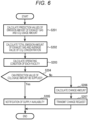
- FIG. 6 is a flowchart illustrating processing executed by an information processing device of a carbon management system according to the second embodiment (see also FIG. 2 as appropriate).
- step S201 the information processing device 41 calculates a prediction value of the emission amount of the exhaust gas and calculates a prediction value of the CO 2 usage amount.
- the information processing device 41 acquires the operation plan information 81a of the CO 2 emission facilities 21 to 23 from the emission-side information system 80 (see FIG. 3 ) via the communication unit 411.
- the calculation unit 413 calculates the prediction value of the emission amount of the exhaust gas on the basis of the above-described operation plan information 81a in addition to the information on the design specification and performance of the CO 2 emission facilities 21 to 23 included in the grid/device attribute information 412a (see FIG. 2 ).
- the calculation unit 413 may calculate the prediction value of the CO 2 emission amount on the basis of the grid/device operation information 412b (see FIG. 2 ) and the operation plan information 81a in addition to the actual data of the emission amount of the exhaust gas included in the CO 2 emission amount/usage amount management information 412d (see FIG. 2 ). That is, the calculation unit 413 may calculate the amount of CO 2 contained in the exhaust gas of the CO 2 emission facilities 21 to 23 on the basis of the application and performance of the CO 2 emission facilities 21 to 23 and the operation status of the CO 2 emission facilities 21 to 23 acquired by the communication unit 411 (information acquisition unit).
- the information processing device 41 acquires the operation plan information 91a of the CO 2 utilization facility 31 from the utilization-side information system 90 (see FIG. 4 ) via the communication unit 411. Then, the calculation unit 413 calculates the prediction value of the CO 2 usage amount on the basis of the above-described operation plan information 91a in addition to the information on the design specification and performance of the CO 2 utilization facilities 31 to 33 included in the grid/device attribute information 412a (see FIG. 2 ).
- calculation unit 413 may calculate the prediction value of the CO 2 usage amount on the basis of the grid/device operation information 412b (see FIG. 2 ) and the operation plan information 91a in addition to the actual data of the CO 2 gas usage amount included in the CO 2 emission amount/usage amount management information 412d (see FIG. 2 ).
- step S202 the calculation unit 413 calculates the total emission amount of the exhaust gas and calculates the average value of the CO 2 concentration. That is, the calculation unit 413 calculates the total amount at each time (each future time) of the exhaust gas delivered from the CO 2 emission facilities 21 to 23 to the processing facility 11 and the average value of the CO 2 concentration in the exhaust gas on the basis of the prediction value of the exhaust gas emission amount and the prediction value of the CO 2 gas usage amount.
- step S203 the calculation unit 413 calculates the operating condition of each facility. That is, the calculation unit 413 calculates the operating condition of the processing facility 11 on the basis of the total amount of the exhaust gas and the average value of the CO 2 concentration. In addition, the calculation unit 413 calculates the operating conditions of the storage facility 12 and the pressure reduction valve 13 at each time (each future time) on the basis of the total emission amount of the exhaust gas, the average value of the CO 2 concentration, and the prediction value of the CO 2 gas usage amount in the CO 2 utilization facilities 31 to 33.
- step S204 the calculation unit 413 determines whether or not the prediction value of the CO 2 usage amount can be supplied. That is, the calculation unit 413 determines whether or not the CO 2 usage amount which is a prediction result can be supplied to the CO 2 utilization facilities 31 to 33 (see FIG. 1 ) on the basis of the total emission amount of the exhaust gas, the average value of the CO 2 concentration in the exhaust gas, the prediction value of the CO 2 usage amount, and the operating condition of each facility. If the prediction value of the CO 2 usage amount can be supplied in step S204 (S204: Yes), the processing of the calculation unit 413 proceeds to step S205.
- step S205 the calculation unit 413 notifies the emission-side information system 80 (see FIG. 3 ) and the utilization-side information system 90 (see FIG. 4 ) that the prediction value of the CO 2 usage amount can be supplied.
- step S204 the processing of the calculation unit 413 proceeds to step S206.
- the calculation unit 413 calculates a change amount of the amount of the exhaust gas emitted by the CO 2 emission facilities 21 to 23 or the amount of the CO 2 gas used by the CO 2 utilization facilities 31 to 33 at each time in the future such that the emission/use of the CO 2 gas is appropriately performed.
- step S207 the calculation unit 413 transmits a change request to the emission-side information system 80 (see FIG. 3 ) or the utilization-side information system 90 (see FIG. 4 ).
- the calculation unit 413 transmits the change amount (increase amount or decrease amount) of the exhaust gas emission amount to the emission-side information system 80 (see FIG. 3 ) via the communication unit 411.
- the calculation unit 413 transmits the change amount (increase amount or decrease amount) of the CO 2 usage amount to the utilization-side information system 90 (see FIG. 4 ) via the communication unit 411.
- the calculation unit 413 may output a notification requesting a business operator holding the CO 2 emission facilities 21 to 23 to reduce the emission amount of the exhaust gas.
- the calculation unit 413 may output a notification requesting the business operator holding the CO 2 emission facilities 21 to 23 to reduce the emission amount of the exhaust gas.
- the calculation unit 413 may output a notification requesting the business operator holding the CO 2 utilization facilities 31 to 33 to reduce the CO 2 usage amount.
- the calculation unit 413 may output a notification requesting the business operator holding the CO 2 utilization facilities 31 to 33 to reduce the CO 2 usage amount.
- the emission-side information system 80 receives the amount of change in the emission amount of the emission gas via the communication device 83, and determines whether or not to accept the change request for the CO 2 emission facility 21 on the basis of the operation plan information 81a. Then, the emission-side information system 80 transmits a response (acceptance or rejection) to the request to the information processing device 41 (see FIG. 1 ) via the communication device 83.
- the utilization-side information system 90 also determines whether or not to accept the change request on the basis of the amount of change in the usage amount of CO 2 gas, and transmits a response to the information processing device 41 (see FIG. 1 ).
- a distribution grid (not illustrated) that supplies at least one of electric power, natural gas (liquefied natural gas or gaseous natural gas), hydrogen, heat, or ammonia to the CO 2 emission facilities 21 to 23 or the CO 2 utilization facilities 31 to 33 may be provided.
- the communication unit 411 (information acquisition unit) of the information processing device 41 acquires the information regarding the restriction on the operation of the distribution grid described above.
- the calculation unit 413 calculates an increase amount or a decrease amount in the amount of the exhaust gas emitted by the CO 2 emission facilities 21 to 23 or an increase amount or a decrease amount in the amount of the CO 2 gas used by the CO 2 utilization facilities 31 to 33 on the basis of the restriction of the operation of the distribution grid.
- the calculation result of the calculation unit 413 is transmitted to the emission-side information system 80 (see FIG. 3 ) or the utilization-side information system 90 (see FIG. 4 ).
- the second embodiment it is possible to change the amount of the exhaust gas or CO 2 gas flowing through the CO 2 distribution grid G1 in the CO 2 distribution grid G1 that collects, recovers, and reuses exhaust gas in an industrial accumulation site or the like.
- a third embodiment is different from the second embodiment in that, in a case where the supply and demand of CO 2 is excessive or insufficient, the calculation unit 413 determines release of CO 2 gas to the atmosphere or the like.
- the other configurations the configuration of the carbon management system 100 and the like: see FIGS. 1 to 4 ) are the same as those of the second embodiment. Therefore, portions different from those of the second embodiment will be described, and description of redundant portions will be omitted.
- FIG. 7 is a flowchart illustrating processing executed by an information processing device of a carbon management system according to the third embodiment (see also FIG. 2 as appropriate) .
- steps S301 to S303 in FIG. 7 is similar to the processing in steps S201 to S203 in the second embodiment (see FIG. 6 ), and thus description thereof is omitted.
- step S304 the calculation unit 413 determines whether or not the demand and the supply of CO 2 are equal. That is, the calculation unit 413 determines whether or not the total usage amount of CO 2 per unit time is equal to the total supply amount of CO 2 per unit time. If the demand and the supply of CO 2 are equal in step S304 (S304: Yes), the processing of the calculation unit 413 proceeds to step S305.
- step S305 the calculation unit 413 notifies the emission-side information system 80 (see FIG. 3 ) and the utilization-side information system 90 (see FIG. 4 ) that a predetermined CO 2 usage amount can be supplied.
- step S304 the processing of the calculation unit 413 proceeds to step S306.
- step S306 the calculation unit 413 determines whether the demand for CO 2 is less than the supply. If the demand for CO 2 is less than the supply in step S306 (S306: Yes), the processing of the calculation unit 413 proceeds to step S307. That is, if the emission amount of the exhaust gas or the CO 2 gas in the CO 2 distribution grid G1 (see FIG. 1 ) is excessively large, the processing of the calculation unit 413 proceeds to step S307.
- step S307 the calculation unit 413 determines to release CO 2 to the atmosphere. Then, in step S308, the calculation unit 413 notifies the CO 2 emission facilities 21 to 23 of the release amount of the exhaust gas to the atmosphere and the release time zone as the determination of the release of CO 2 to the atmosphere. That is, when the total amount of CO 2 used by the CO 2 utilization facilities 31 to 33 is smaller than the total amount of CO 2 contained in the exhaust gas of the CO 2 emission facilities 21 to 23, the calculation unit 413 sets the operating condition of the processing facility 11 so as to release, to the atmosphere, CO 2 in an amount exceeding the amount of CO 2 used by the CO 2 utilization facilities 31 to 33.
- the calculation unit 413 may set the operating condition of the processing facility 11 so as to release, to the atmosphere, CO 2 in an amount exceeding the amount of CO 2 used in the CO 2 utilization facilities 31 to 33.
- step S309 the calculation unit 413 purchases a CO 2 emission right corresponding to the amount of CO 2 released to the atmosphere from a business operator that holds the CO 2 emission right.
- the calculation unit 413 may be set to purchase the CO 2 emission right from the CO 2 emission right transaction market 70 (see FIG. 1 ).
- the purchase described above is not particularly required to be performed simultaneously with the release of the CO 2 gas to the atmosphere, and may be performed before or after the release.
- step S310 if the demand for CO 2 is larger than the supply in step S306 (S306: Yes), the processing of the calculation unit 413 proceeds to step S310. That is, if the amount of the exhaust gas or the CO 2 gas in the CO 2 distribution grid G1 (see FIG. 1 ) is excessively small, the processing of the calculation unit 413 proceeds to step S310.
- step S310 the calculation unit 413 notifies that the CO 2 gas cannot be supplied. That is, the calculation unit 413 transmits a notification, which indicates that a predetermined amount of CO 2 gas is not supplied to the CO 2 utilization facilities 31 to 33 in a predetermined time zone, to the terminal or the like of the CO 2 user via the communication unit 411.
- step S311 the calculation unit 413 pays a predetermined penalty corresponding to the shortage amount of CO 2 gas to the CO 2 user on the basis of the contract made in advance. That is, when the total amount of CO 2 used by the CO 2 utilization facilities 31 to 33 is larger than the total amount of CO 2 contained in the exhaust gas of the CO 2 emission facilities 21 to 23, the calculation unit 413 performs setting so as to provide money corresponding to the shortage of CO 2 to the business operator holding the CO 2 utilization facilities 31 to 33.
- a fourth embodiment is different from the first embodiment in that, when excess or insufficiency of CO 2 gas occurs, the calculation unit 413 requests another business operator to participate in the carbon management system 100.
- the other configurations (the configuration of the carbon management system 100 and the like: see FIGS. 1 to 4 ) are the same as those of the first embodiment. Therefore, portions different from those of the first embodiment will be described, and description of redundant portions will be omitted.
- a fifth embodiment is different from the first embodiment in that a decarbonization amount is allocated to a business operator participating in a carbon management system 100.
- the other configurations (the configuration of the carbon management system 100 and the like: see FIGS. 1 to 4 ) are the same as those of the first embodiment. Therefore, portions different from those of the first embodiment will be described, and description of redundant portions will be omitted.
- the calculation unit 413 of the information processing device 41 illustrated in FIG. 2 acquires information on the emission amount (flow rate/CO 2 concentration) of exhaust gas from the measurement/communication devices 6a to 6c provided at the inflow points A1 to A3 of the CO 2 distribution grid G1 (see FIG. 1 ) and the emission-side information system 80.
- the information on the emission amount of the exhaust gas is stored as the CO 2 emission amount/usage amount management information 412d (see FIG. 2 ) in association with the identification information of the CO 2 emission facilities 21 to 23 as emission sources.
- the carbon management system 100 includes the storage facility 12 and the pressure reduction valve 13 has been described, but the present invention is not limited thereto. That is, at least one of the storage facility 12 or the pressure reduction valve 13 may be omitted.
- the pressure reduction valve 13 is provided in the conduit 5i (second conduit) has been described, but the number and installation location of the pressure reduction valves 13 can be appropriately changed.
- the pressure reduction valve may be provided in another conduit 5g (second conduit) or the conduit 5h (second conduit).
- the pressure reduction valve may be provided in at least one of the conduits 5a to 5c (first conduits) connected to the CO 2 emission facilities 21 to 23.
- the configuration in which the storage facility 12 is connected to the conduits 5e and 5f (second conduits) on the downstream side of the processing facility 11 is not limited to this configuration.
- the storage facility 12 may be provided in the conduit 5d (first conduit) on the upstream side of the processing facility 11.
- each embodiment can be appropriately combined.
- the second embodiment (see FIG. 6 ) and the third embodiment (see FIG. 7 ) may be combined, and the calculation unit 413 may perform the following processing. That is, in a case where the demand amount of CO 2 is smaller than the supply amount of CO 2 , when a change request to reduce the emission amount of the exhaust gas is issued to the business operator of the CO 2 emission facilities 21 to 23, but the change request is not accepted, the calculation unit 413 may determine the released of CO 2 to the atmosphere.
- the calculation unit 413 may determine payment of the penalty to the business operator.
- each embodiment can also be applied to the distribution of carbon-containing components such as CO and CH 4 contained in the exhaust gas.
- a method for measuring the carbon-containing component in the exhaust gas mass spectrometry, gas chromatography, infrared spectroscopy, cavity ring down spectroscopy, or the like is used.
- all or a part of programs for implementing the functions (carbon management methods) of the carbon management system 100 and the like described in each embodiment may be executed by one or more computers such as a server (not illustrated). All or a part of the programs may be realized in hardware, for example, by designing the programs as an integrated circuit.
- each of the configurations and functions described in the embodiments may be realized by software by a processor interpreting and executing a program for realizing each function.
- Information such as a program, a table, and a file for realizing each function may be stored in a recording device such as a solid state drive (SSD) or a recording medium such as an IC card, an SD card, a CD-ROM, and a DVD in addition to a memory and a hard disk.
- SSD solid state drive
- the program described above can also be provided via a communication line.
- each embodiment has been described in detail for easy understanding of the present invention, and is not necessarily limited to those having all the described configurations.
- the above-described mechanisms and configurations are described in consideration of necessity for the description, and all the mechanisms and configurations in the product are not necessarily described.
Landscapes
- Business, Economics & Management (AREA)
- Engineering & Computer Science (AREA)
- Economics (AREA)
- Human Resources & Organizations (AREA)
- Strategic Management (AREA)
- Theoretical Computer Science (AREA)
- Marketing (AREA)
- Physics & Mathematics (AREA)
- General Business, Economics & Management (AREA)
- General Physics & Mathematics (AREA)
- Entrepreneurship & Innovation (AREA)
- Tourism & Hospitality (AREA)
- Operations Research (AREA)
- Development Economics (AREA)
- Quality & Reliability (AREA)
- Chemical & Material Sciences (AREA)
- Accounting & Taxation (AREA)
- Game Theory and Decision Science (AREA)
- Health & Medical Sciences (AREA)
- Finance (AREA)
- Technology Law (AREA)
- Chemical Kinetics & Catalysis (AREA)
- Oil, Petroleum & Natural Gas (AREA)
- General Health & Medical Sciences (AREA)
- Primary Health Care (AREA)
- Life Sciences & Earth Sciences (AREA)
- Sustainable Development (AREA)
- Water Supply & Treatment (AREA)
- Public Health (AREA)
- General Chemical & Material Sciences (AREA)
- Analytical Chemistry (AREA)
- Educational Administration (AREA)
- Management, Administration, Business Operations System, And Electronic Commerce (AREA)
Abstract
Description
- The present invention relates to a carbon management system and an information processing device.
- In order to realize a carbon neutral society, introduction of a CO2 reduction technology is in progress. In addition, there is a concept of a CO2 distribution grid for reusing exhaust gas at an industrial accumulation site in order to reduce a cost burden.
- PTL 1 describes, in this concept, that a CO2 emitter, a CO2 user, a CO2 pipe connecting them, and a carbon recycling device are provided, a scheduled amount of CO2 used for carbon recycling is notified to a constituent business operator of a complex, and CO2 is supplied from a carbon dioxide supplier on the basis of the scheduled CO2 usage amount.
- PTL 1:
JP 2022-007936 A - In order to realize the concept of the CO2 distribution grid, it is desirable to adjust the supply and demand balance of CO2, and perform CO2 processing and the like appropriately, but such a technology is not described in PTL 1.
- In addition, CO2 is generated as a by-product of the main business of the CO2 emitter, and the emission amount of the exhaust gas containing CO2 is not easily changed according to the use of the CO2 user.
- Furthermore, when the exhaust gas from the factory group is received as it is in the operation plan, the fluctuation range of the exhaust gas processing amount becomes large, and thus, it becomes difficult to operate a CO2 recovery facility (CO2 processing facility).
- In this regard, an object of the present invention is to provide a carbon management system or the like that recovers CO2 from exhaust gas from a factory group and supplies the CO2 to a plurality of CO2 users.
- In order to solve the above problems, a carbon management system according to the present invention includes: a plurality of emission facilities which emit an exhaust gas containing CO2; a processing facility which separates a CO2 gas from the exhaust gas emitted from the emission facility; a plurality of utilization facilities which use the CO2 gas separated in the processing facility; a first conduit which guides, to the processing facility, the exhaust gas emitted from the plurality of emission facilities; a second conduit which guides the CO2 gas separated in the processing facility to the plurality of utilization facilities; a storage facility which is connected to the first conduit or the second conduit and stores the CO2 gas; and an information processing device which sets operating conditions of the processing facility and the storage facility.
- According to the present invention, it is possible to provide a carbon management system or the like that recovers CO2 from an exhaust gas from a factory group and supplies the CO2 to a plurality of CO2 users.
-
- [
FIG. 1] FIG. 1 is a configuration diagram of a carbon management system according to a first embodiment. - [
FIG. 2] FIG. 2 is a functional block diagram illustrating a configuration of an information processing device included in the carbon management system according to the first embodiment. - [
FIG. 3] FIG. 3 is a functional block diagram illustrating a configuration of an emission-side information system included in the carbon management system according to the first embodiment. - [
FIG. 4] FIG. 4 is a functional block diagram illustrating a configuration of a utilization-side information system included in the carbon management system according to the first embodiment. - [
FIG. 5] FIG. 5 is a flowchart illustrating processing executed by the information processing device of the carbon management system according to the first embodiment. - [
FIG. 6] FIG. 6 is a flowchart illustrating processing executed by an information processing device of a carbon management system according to a second embodiment. - [
FIG. 7] FIG. 7 is a flowchart illustrating processing executed by an information processing device of a carbon management system according to a third embodiment. - Hereinafter, each embodiment of the present invention will be described with reference to the drawings. Note that the same components are denoted by the same reference numerals, and in a case where descriptions thereof overlap, the description thereof may be omitted. In addition, the present invention is not limited to the following embodiments.
-
FIG. 1 is a configuration diagram of acarbon management system 100 according to a first embodiment. - The
carbon management system 100 is a system that manages distribution of CO2 (carbon dioxide) supplied from CO2 emission facilities 21 to 23 (emission facility) to CO2 utilization facilities 31 to 33 (utilization facility) via a CO2 distribution grid G1. As illustrated inFIG. 1 , thecarbon management system 100 includes the CO2 emission facilities 21 to 23, aprocessing facility 11, astorage facility 12, apressure reduction valve 13, the CO2 utilization facilities 31 to 33, and aninformation processing device 41. In addition to the configuration described above, thecarbon management system 100 includesconduits 5a to 5d as "first conduits" for guiding, to theprocessing facility 11, the exhaust gas emitted from the CO2 emission facilities 21 to 23. Further, thecarbon management system 100 includesconduits 5e to 5i as "second conduits" for guiding the CO2 gas separated in theprocessing facility 11 to the plurality of CO2 utilization facilities 31 to 33. - The CO2 emission facilities 21 to 23 illustrated in
FIG. 1 are facilities that emit an exhaust gas containing CO2. Examples of such a CO2 emission facilities 21 to 23 include a factory and a power plant. Theconduits 5a to 5c are connected to the CO2 emission facilities 21 to 23 in a one-to-one correspondence. Then, the CO2 gas flowing through theconduits 5a to 5c is merged in theconduit 5d, and the merged CO2 gas is guided to theprocessing facility 11 through theconduit 5d. - The
processing facility 11 is a facility that separates (recovers) a CO2 gas from the exhaust gas emitted from the CO2 emission facilities 21 to 23. As a method for separating a CO2 gas, for example, there is a chemical absorption method in which an alkaline CO2 absorbent and an exhaust gas are brought into contact with each other to absorb CO2 in the exhaust gas into the CO2 absorbent. In addition, there are a physical adsorption method using an adsorbent using van der Waals force, a chemical adsorption method in which an alkaline CO2 adsorbent (solid) and an exhaust gas are brought into contact with each other to adsorb CO2 in the exhaust gas to the CO2 adsorbent, and the like. Note that a process of concentrating a CO2 gas is also included in the separation of a CO2 gas. - The
storage facility 12 is a facility that stores a CO2 gas. As such astorage facility 12, for example, a tank is used. Then, a CO2 gas is guided from theprocessing facility 11 to thestorage facility 12 via theconduit 5e. The CO2 gas temporarily stored in thestorage facility 12 is supplied to the CO2 utilization facilities 31 and 32 via theconduits 5f to 5i (second conduits). That is, thestorage facility 12 is connected to the "second conduit" described above. More specifically, the CO2 gas flowing from thestorage facility 12 into theconduit 5f is divided into theconduits 5g to 5i, and is further supplied to the CO2 utilization facilities 31 to 33. Note that theconduits 5g to 5i are connected to the CO2 utilization facilities 31 to 33 in a one-to-one correspondence. - The CO2 utilization facilities 31 to 33 are facilities utilizing the CO2 gas separated by the
processing facility 11, and is provided in an industrial accumulation place or the like. Since the CO2 gas having a certain concentration or higher is used in the CO2 utilization facilities 31 to 33, basically, the CO2 gas is supplied to the CO2 emission facilities 21 to 23 via theprocessing facility 11. However, when the CO2 concentration of the emission gas is sufficiently high, the CO2 utilization facilities 31 to 33 and the CO2 emission facilities 21 to 23 may be connected without theprocessing facility 11. In addition, inFIG. 1 , three CO2 emission facilities 21 to 23 and three CO2 utilization facilities 31 to 33 are illustrated, but the number of CO2 emission facilities or CO2 utilization facilities is not limited thereto, and may be one or more. - The CO2 distribution grid G1 illustrated in
FIG. 1 is a pipeline network through which an exhaust gas containing CO2 and a CO2 gas flow. Note that portions where the exhaust gas containing CO2 enters the CO2 distribution grid G1 are referred to as inflow points A1 to A3. In addition, portions where the CO2 gas flows out from the CO2 distribution grid G1 are referred to as outflow points B1 to B3. In the example ofFIG. 1 , the inflow point A1 exists in theconduit 5a connected to the CO2 emission facility 21. Similarly, the inflow point A2 exists in theconduit 5b, and the inflow point A3 exists in theconduit 5c. On the other hand, the outflow point B1 exists in theconduit 5g connected to the CO2 utilization facility 31. Similarly, the outflow point B2 exists in theconduit 5h, and the outflow point B3 exists in theconduit 5i. - Note that in the example of
FIG. 1 , theconduits conduits - As illustrated in
FIG. 1 , theprocessing facility 11, thestorage facility 12, and thepressure reduction valve 13 are included in the CO2 distribution grid G1. Thepressure reduction valve 13 is a valve that adjusts a flow rate of CO2 gas (or exhaust gas) flowing in the CO2 distribution grid G1. In the example ofFIG. 1 , apressure reduction valve 13 is provided in theconduit 5i (second conduit) connected to the CO2 utilization facility 33. Note that the flow rate of the CO2 gas flowing through theconduit 5i decreases as the opening degree of thepressure reduction valve 13 decreases. Therefore, by adjusting the opening degree of thepressure reduction valve 13, the flow rate ratio of CO2 in theconduits - As illustrated in
FIG. 1 , a measurement/communication device 6a is provided near the inflow point A1 in theconduit 5a. The measurement/communication device 6a measures the flow rate, the pressure, and the CO2 concentration of the exhaust gas flowing from the CO2 emission facility 21 to the CO2 distribution grid G1 via theconduit 5a, and transmits the measurement result to a CO2 distribution gridmanagement information system 40. Similarly, a measurement/communication device 6b is provided in theconduit 5b, and a measurement/communication device 6c is provided in anotherconduit 5c. Note that theinformation processing device 41 of the CO2 distribution gridmanagement information system 40 may calculate the flow rate, the pressure, and the CO2 concentration of the exhaust gas on the basis of the application, performance, and operation status of the CO2 emission facility 21. - As illustrated in
FIG. 1 , a measurement/communication device 6g is provided near the outflow point B1 of theconduit 5g. The measurement/communication device 6g measures the flow rate, the pressure, and the CO2 concentration of the CO2 gas supplied from the CO2 distribution grid G1 to the CO2 utilization facility 31, and transmits the measurement result to the CO2 distribution gridmanagement information system 40. Similarly, a measurement/communication device 6h is provided in theconduit 5h, and a measurement/communication device 6i is provided in anotherconduit 5i. Note that theinformation processing device 41 of the CO2 distribution gridmanagement information system 40 may calculate the flow rate, the pressure, and the CO2 concentration of the CO2 gas used in the CO2 utilization facility 31 on the basis of the application, performance, and operation status of the CO2 utilization facility 31. - In the example of
FIG. 1 , a measurement/communication device 6d is provided in theprocessing facility 11, and a measurement/communication device 6e is also provided in thestorage facility 12. Note that instead of the measurement/communication devices conduits communication device 6f is also provided near thepressure reduction valve 13 in theconduit 5i. The measurement results of these measurement/communication devices management information system 40. - The
information processing device 41 illustrated inFIG. 1 is a device that sets operating conditions of theprocessing facility 11, thestorage facility 12, and thepressure reduction valve 13, and is included in the CO2 distribution gridmanagement information system 40. -
FIG. 2 is a functional block diagram illustrating a configuration of theinformation processing device 41. - As illustrated in
FIG. 2 , theinformation processing device 41 includes a communication unit 411 (information acquisition unit), astorage unit 412, and acalculation unit 413. Thecommunication unit 411 acquires information on the CO2 emission facilities 21 to 23 (seeFIG. 1 ), the processing facility 11 (seeFIG. 1 ), the CO2 utilization facilities 31 to 33 (seeFIG. 1 ), and the like. For example, thecommunication unit 411 acquires the emission amount (flow rate/CO2 concentration) of the exhaust gas of each of the CO2 emission facilities 21 to 23. Note that the present embodiment discloses an example in which the information acquisition unit is thecommunication unit 411, but the information acquisition unit may be an input device that acquires information by input from a user. - The
storage unit 412 stores the information acquired by the communication unit 411 (information acquisition unit) . That is, thestorage unit 412 stores grid/device attribute information 412a, grid/device operation information 412b,contract information 412c, CO2 emission amount/usageamount management information 412d, and CO2 emissionright management information 412e. The grid/device attribute information 412a includes not only information indicating design specifications of the CO2 emission facilities 21 to 23 (seeFIG. 1 ) and the CO2 utilization facilities 31 to 33 (seeFIG. 1 ) but also information indicating design specifications, applications, and performance of each facility in the CO2 distribution grid G1 (seeFIG. 1 ). The grid/device operation information 412b is information indicating the operation status of each facility included in the CO2 distribution grid G1 (seeFIG. 1 ) in addition to the CO2 emission facilities 21 to 23 (seeFIG. 1 ) and the CO2 utilization facilities 31 to 33 (seeFIG. 1 ). - The
contract information 412c is information indicating a contract content such as a supply amount of CO2 gas (supply amount per predetermined period) to the CO2 utilization facilities 31 to 33 (seeFIG. 1 ). The CO2 emission amount/usageamount management information 412d is information including the amount of the exhaust gas emitted from the CO2 emission facilities 21 to 23 (seeFIG. 1 ) and the actual value of the amount of CO2 gas supplied to the CO2 utilization facilities 31 to 33 (seeFIG. 1 ). The CO2 emissionright management information 412e is information for specifying a CO2 emission right regarding the release of the CO2 gas to the atmosphere. The CO2 emission right is usually purchased from a CO2 emission right transaction market 70 (seeFIG. 1 ). - The
calculation unit 413 illustrated inFIG. 2 sets the operating conditions of the processing facility 11 (seeFIG. 1 ), the storage facility 12 (seeFIG. 1 ), and the pressure reduction valve 13 (seeFIG. 1 ). Thecalculation unit 413 includes a CO2emission management unit 413a and agrid calculation unit 413b. The CO2emission management unit 413a calculates the total emission amount of the exhaust gas and the like. Thegrid calculation unit 413b sets the operating condition of each facility included in the CO2 distribution grid G1 (seeFIG. 1 ) on the basis of the total emission amount of the exhaust gas and the like. Note that details of the processing of thecalculation unit 413 will be described later. -
FIG. 3 is a functional block diagram illustrating a configuration of an emission-side information system 80. - The emission-
side information system 80 illustrated inFIG. 3 is a system that monitors, controls, and manages the CO2 emission facility 21, and is connected to the CO2 emission facility 21 via a communication line and can communicate with the information processing device 41 (seeFIG. 1 ). The emission-side information system 80 includes astorage device 81, acalculation device 82, and acommunication device 83. - The
storage device 81 storesoperation plan information 81a and CO2emission amount information 81b. Theoperation plan information 81a is information indicating the expectation of the future (for example, several hours or several days) operation of the CO2 emission facility 21. The CO2emission amount information 81b is information indicating the expectation of the future CO2 emission amount of the CO2 emission facility 21. Thecalculation device 82 performs processing related to monitoring, control, and management of the CO2 emission facility 21. Thecommunication device 83 transmits the calculation result of thecalculation device 82 to the CO2 emission facility 21 and the information processing device 41 (not illustrated). Note that each of the other CO2 emission facilities 22 and 23 (seeFIG. 1 ) is also provided with an emission-side information system (not illustrated). -
FIG. 4 is a functional block diagram illustrating a configuration of a utilization-side information system 90. - The utilization-
side information system 90 illustrated inFIG. 4 is a system that monitors, controls, and manages the CO2 utilization facility 31, and is connected to the CO2 utilization facility 31 via a communication line and can communicate with the information processing device 41 (seeFIG. 1 ). The utilization-side information system 90 includes astorage device 91, acalculation device 92, and acommunication device 93. - The
storage device 91 storesoperation plan information 91a and CO2usage amount information 91b. Theoperation plan information 91a is information indicating the expectation of the future (for example, several hours or several days) operation of the CO2 utilization facility 31. The CO2usage amount information 91b is information indicating an expectation of the future CO2 usage amount of the CO2 utilization facility 31. Thecalculation device 92 performs processing related to monitoring, control, and management of the CO2 utilization facility 31. Thecommunication device 93 transmits the calculation result of thecalculation device 92 to the CO2 utilization facility 31 and the information processing device 41 (not illustrated). Note that each of the other CO2 utilization facilities 32 and 33 (seeFIG. 1 ) is also provided with a utilization-side information system (not illustrated). -
FIG. 5 is a flowchart illustrating processing executed by the information processing device (see alsoFIG. 2 as appropriate). - In step S101, the
information processing device 41 causes thecalculation unit 413 to calculate the total emission amount of the exhaust gas. That is, thecalculation unit 413 calculates the total emission amount of the exhaust gas of the entirecarbon management system 100 on the basis of the amount of the exhaust gas emitted by each of the CO2 emission facilities 21 to 23 (seeFIG. 1 ) acquired by the communication unit 411 (information acquisition unit). Note that the amount of the exhaust gas emitted by each of the CO2 emission facilities 21 to 23 (seeFIG. 1 ) is calculated on the basis of the design specifications of the CO2 emission facilities 21 to 23 and the operation status of the CO2 emission facilities 21 to 23 acquired by the communication unit 411 (information acquisition unit). - In step S102, the
information processing device 41 causes thecalculation unit 413 to calculate the operating condition of each facility. That is, thecalculation unit 413 calculates the operating conditions of theprocessing facility 11, thestorage facility 12, and thepressure reduction valve 13 on the basis of the total emission amount of the exhaust gas. Specifically, thecalculation unit 413 calculates the total emission amount of the exhaust gas delivered from the CO2 emission facilities 21 to 23 (seeFIG. 1 ) to the processing facility 11 (seeFIG. 1 ) and the average value of the CO2 concentration, on the basis of the emission amount (flow rate/CO2 concentration) of the exhaust gas collected via thecommunication unit 411, and calculates the operating conditions of theprocessing facility 11, thestorage facility 12, and thepressure reduction valve 13 on the basis of these respective values. Here, the operating condition of theprocessing facility 11 is, for example, a processing amount of the processing facility 11 (the amount of CO2 contained in the CO2 gas). The operating condition of thestorage facility 12 is, for example, the storage amount increment of the storage facility 12 (a blowing amount of a compressor accompanying the storage facility 12). The operating condition of thepressure reduction valve 13 is, for example, the operation amount (valve opening degree) of thepressure reduction valve 13. - In step S103, the
information processing device 41 transmits information on the operating condition to each facility by thecommunication unit 411. As a result, the delivery amount of the CO2 gas is controlled, so that the amount of the CO2 gas supplied to the CO2 utilization facilities 31 to 33 (seeFIG. 1 ) can be adjusted. Note that thecalculation unit 413 may determine the amount of CO2 gas distributed to the CO2 utilization facilities 31 to 33 on the basis of thecontract information 412c described above, and set the operating conditions of thestorage facility 12 and thepressure reduction valve 13 such that the CO2 gas is supplied according to the amount of CO2 gas distributed. - Note that, in step S102, the
calculation unit 413 may determine the processing amount of theprocessing facility 11 and the temporary storage amount of the storage facility 12 (seeFIG. 1 ) on the basis of the total emission amount of the exhaust gas and the design value of the processing amount (processing amount per unit time) of the processing facility 11 (seeFIG. 1 ) and the design value of the storage amount of thestorage facility 12 which are stored in advance in thestorage unit 412. In this case, thecalculation unit 413 calculates the operating conditions of theprocessing facility 11, thestorage facility 12, and thepressure reduction valve 13 so as to satisfy the determined processing amount and storage amount. - In addition, for example, the
calculation unit 413 may perform the following processing in step S102. That is, thecalculation unit 413 may calculate the operating conditions of theprocessing facility 11, thestorage facility 12, and thepressure reduction valve 13 on the basis of the amount of the exhaust gas emitted by the CO2 emission facilities 21 to 23 (seeFIG. 1 ) and the amount of the CO2 gas used by the CO2 utilization facilities 31 to 33 (seeFIG. 1 ). Note that the amount of CO2 gas used by the CO2 utilization facilities 31 to 33 is calculated on the basis of the design specification of the CO2 utilization facilities 31 to 33 and the operation status of the CO2 utilization facilities 31 to 33 acquired by the communication unit 411 (information acquisition unit). - In addition, for example, the
calculation unit 413 may perform the following processing in step S102. That is, thecalculation unit 413 may determine the processing amount of the processing facility 11 (seeFIG. 1 ) and the temporary storage amount in the storage facility 12 (seeFIG. 1 ) on the basis of the amount of the exhaust gas emitted by the CO2 emission facilities 21 to 23 (seeFIG. 1 ), the amount of CO2 gas used by the CO2 utilization facilities 31 to 33 (seeFIG. 1 ), and the design value of the processing amount (processing amount per unit time) of theprocessing facility 11 and the design value of the storage amount of thestorage facility 12 which are stored in advance in thestorage unit 412. In this case, thecalculation unit 413 calculates the operating conditions of theprocessing facility 11, thestorage facility 12, and thepressure reduction valve 13 so as to satisfy the determined processing amount and storage amount. - In addition, for example, the
calculation unit 413 may perform the following processing in step S102. That is, thecalculation unit 413 calculates the total emission amount of the exhaust gas delivered from all the CO2 emission facilities 21 to 23 (seeFIG. 1 ) to theprocessing facility 11 and the average value of the CO2 concentration on the basis of the emission amount (flow rate and CO2 concentration) of the exhaust gas collected via thecommunication unit 411, and calculates the operating condition of theprocessing facility 11. Then, thecalculation unit 413 calculates the operating conditions of thestorage facility 12 and thepressure reduction valve 13 on the basis of the total emission amount of the exhaust gas, the average value of the CO2 concentration, and the amount (flow rate/CO2 concentration) of the CO2 gas used by the CO2 utilization facilities 31 to 33 (seeFIG. 1 ). Also by such a method, the amount of CO2 gas supplied to the CO2 utilization facilities 31 to 33 can be appropriately adjusted. - Note that in the processing facility 11 (see
FIG. 1 ), the storage facility 12 (seeFIG. 1 ), and the pressure reduction valve 13 (seeFIG. 1 ), there are an upper limit value and a lower limit value of an operation amount determined from an operation status, in addition to predetermined upper limit values and lower limit values determined from design specifications of these facilities. Therefore, the operating condition calculated by thecalculation unit 413 may deviate from a predetermined range of the upper limit value and the lower limit value. For example, in a case where the operating conditions of theprocessing facility 11, thestorage facility 12, and thepressure reduction valve 13 are not executable, thecalculation unit 413 calculates the amount of the exhaust gas emitted by the CO2 emission facilities 21 to 23 (seeFIG. 1 ) or the amount of the CO2 gas used by the CO2 utilization facilities 31 to 33 (seeFIG. 1 ) so as to satisfy the executable processing amount of theprocessing facility 11 and the executable storage amount of thestorage facility 12. The calculation result of thecalculation unit 413 is transmitted to the emission-side information system 80 (seeFIG. 3 ) or the utilization-side information system 90 (seeFIG. 4 ) via thecommunication unit 411. - As described above, CO2 is generated as the by-product of the main business of the CO2 emitter, so that when the exhaust gas from the factory group is accepted as the operation plan, the fluctuation range of the exhaust gas processing amount becomes large. Therefore, the
calculation unit 413 preferably sets the operating conditions of theprocessing facility 11 and thestorage facility 12 so as to stabilize the facility load and the operation load of theprocessing facility 11. - When receiving the value (changed value) of the emission amount of the exhaust gas from the information processing device 41 (see
FIG. 1 ) via thecommunication device 83, the emission-side information system 80 (seeFIG. 3 ) determines whether or not to accept the request to change the emission amount on the basis of theoperation plan information 81a of the CO2 emission facility 21. Then, the emission-side information system 80 transmits a response (acceptance or rejection) to the request to change the emission amount to theinformation processing device 41. - In addition, when receiving the value (changed value) of the usage amount of the CO2 gas from the information processing device 41 (see
FIG. 1 ) via thecommunication device 93, the utilization-side information system 90 (seeFIG. 4 ) determines whether or not to accept the request to change the usage amount on the basis of theoperation plan information 91a of the CO2 utilization facility 31. Then, the utilization-side information system 90 transmits a response (acceptance or rejection) to the request to change the usage amount to theinformation processing device 41. - In addition to the operating conditions of the
processing facility 11, thestorage facility 12, and thepressure reduction valve 13, thecalculation unit 413 of theinformation processing device 41 determines whether or not the processing of the CO2 gas is executable on the basis of the emission amount of the CO2 emission facilities 21 to 23, the usage amount of the CO2 utilization facilities 31 to 31, and the response (acceptance or rejection) of the CO2 emission facilities 21 to 23 and the CO2 utilization facilities 31 to 33. - Note that, depending on the business operator operating the CO2 emission facilities 21 to 23, there may be a case where it is not desired for a third party to know the information on the emission amount of the exhaust gas. This is because there is a possibility that the operation status and the financial status of the CO2 emission facilities 21 to 23 are estimated on the basis of the emission amount of the exhaust gas. Note that the same applies to the business operator operating the CO2 utilization facilities 31 to 33. In such a case, the
calculation unit 413 causes the business operator to provide a difference between the amount of CO2 contained in the exhaust gas of a specific CO2 emission facility and the usage amount of the CO2 gas in a specific CO2 utilization facility. - Here, it is assumed that the business operator of at least one of the specific CO2 emission facility or the specific CO2 utilization facility applies not to disclose the emission amount of the exhaust gas (or the CO2 emission amount) and the CO2 usage amount to the
information processing device 41 in advance from a terminal (not illustrated) of the business operator. While the value of the difference described above is provided to thecalculation unit 413, the emission amount of the exhaust gas and the usage amount of the CO2 gas are not particularly provided. Therefore, it is possible to prevent the operation status and the financial status of each facility from being estimated by a third party. - In such a case, the
information processing device 41 acquires, by the communication unit 411 (information acquisition unit), the emission amount of the exhaust gas emitted by CO2 emission facilities other than the specific CO2 emission facility among the plurality of CO2 emission facilities 21 to 23 (seeFIG. 1 ) and the usage amount of the CO2 gas used by CO2 utilization facilities other than the specific CO2 utilization facility among the plurality of CO2 utilization facilities 31 to 33 (seeFIG. 1 ), and acquires the difference between the amount of CO2 contained in the exhaust gas of the specific CO2 emission facility and the amount of the CO2 gas used by the specific CO2 utilization facility. Then, thecalculation unit 413 calculates the operating conditions of the processing facility 11 (seeFIG. 1 ), the storage facility 12 (seeFIG. 1 ), and the pressure reduction valve 13 (seeFIG. 1 ) on the basis of the emission amount of the exhaust gas emitted by the emission facilities other than the specific emission facility among the plurality of CO2 emission facilities 21 to 23, the usage amount of the CO2 gas used by the CO2 utilization facilities other than the specific CO2 utilization facility among the plurality of CO2 utilization facilities 31 to 33, and the above-described difference. - Note that a distribution grid (not illustrated) that supplies at least one of electric power, natural gas (liquefied natural gas or gaseous natural gas), hydrogen, heat, or ammonia to the CO2 emission facilities 21 to 23 or the CO2 utilization facilities 31 to 33 may be provided. In such a configuration, the communication unit 411 (information acquisition unit) of the
information processing device 41 acquires the information regarding the restriction on the operation of the distribution grid described above. Then, thecalculation unit 413 sets the operating conditions of theprocessing facility 11, thestorage facility 12, and thepressure reduction valve 13 on the basis of the restriction of the operation of the distribution grid. The information on the operating condition set by thecalculation unit 413 is transmitted to the emission-side information system 80 (seeFIG. 3 ) and the utilization-side information system 90 (seeFIG. 4 ). - According to the first embodiment, the
calculation unit 413 sets the operating condition of each facility on the basis of the total emission amount of the exhaust gas and the like. As a result, the exhaust gas emitted from the CO2 emission facilities 21 to 23 can be appropriately processed by theprocessing facility 11, and the CO2 gas can be supplied from theprocessing facility 11 to the CO2 utilization facilities 31 to 33. That is, CO2 can be recovered from the exhaust gas from the factory group and supplied to a plurality of CO2 users. In addition, according to the first embodiment, the CO2 distribution grid G1 can be controlled in real time. - In a second embodiment, an embodiment related to an operation plan of the CO2 distribution grid G1 (see
FIG. 1 ) will be described. Specifically, the second embodiment is different from the first embodiment in that the calculation unit 413 (seeFIG. 2 ) issues a request to change the CO2 emission amount or the CO2 usage amount when the CO2 usage amount is excessive or insufficient. Note that the other configurations (the configuration of thecarbon management system 100 and the like: seeFIGS. 1 to 4 ) are the same as those of the first embodiment. In addition, the measurement/communication devices 6a to 6i (seeFIG. 1 ) of the inflow points A1 to A3, the outflow points B1 to B3, theprocessing facility 11, thestorage facility 12, and thepressure reduction valve 13 are not particularly necessary. Hereinafter, portions different from those of the first embodiment will be described, and description of redundant portions will be omitted. -
FIG. 6 is a flowchart illustrating processing executed by an information processing device of a carbon management system according to the second embodiment (see alsoFIG. 2 as appropriate). - In step S201, the
information processing device 41 calculates a prediction value of the emission amount of the exhaust gas and calculates a prediction value of the CO2 usage amount. First, theinformation processing device 41 acquires theoperation plan information 81a of the CO2 emission facilities 21 to 23 from the emission-side information system 80 (seeFIG. 3 ) via thecommunication unit 411. Then, thecalculation unit 413 calculates the prediction value of the emission amount of the exhaust gas on the basis of the above-describedoperation plan information 81a in addition to the information on the design specification and performance of the CO2 emission facilities 21 to 23 included in the grid/device attribute information 412a (seeFIG. 2 ). - Note that the
calculation unit 413 may calculate the prediction value of the CO2 emission amount on the basis of the grid/device operation information 412b (seeFIG. 2 ) and theoperation plan information 81a in addition to the actual data of the emission amount of the exhaust gas included in the CO2 emission amount/usageamount management information 412d (seeFIG. 2 ). That is, thecalculation unit 413 may calculate the amount of CO2 contained in the exhaust gas of the CO2 emission facilities 21 to 23 on the basis of the application and performance of the CO2 emission facilities 21 to 23 and the operation status of the CO2 emission facilities 21 to 23 acquired by the communication unit 411 (information acquisition unit). - In addition, when calculating the prediction value of the CO2 usage amount in step S201, the
information processing device 41 acquires theoperation plan information 91a of the CO2 utilization facility 31 from the utilization-side information system 90 (seeFIG. 4 ) via thecommunication unit 411. Then, thecalculation unit 413 calculates the prediction value of the CO2 usage amount on the basis of the above-describedoperation plan information 91a in addition to the information on the design specification and performance of the CO2 utilization facilities 31 to 33 included in the grid/device attribute information 412a (seeFIG. 2 ). - Note that the
calculation unit 413 may calculate the prediction value of the CO2 usage amount on the basis of the grid/device operation information 412b (seeFIG. 2 ) and theoperation plan information 91a in addition to the actual data of the CO2 gas usage amount included in the CO2 emission amount/usageamount management information 412d (seeFIG. 2 ). - Next, in step S202, the
calculation unit 413 calculates the total emission amount of the exhaust gas and calculates the average value of the CO2 concentration. That is, thecalculation unit 413 calculates the total amount at each time (each future time) of the exhaust gas delivered from the CO2 emission facilities 21 to 23 to theprocessing facility 11 and the average value of the CO2 concentration in the exhaust gas on the basis of the prediction value of the exhaust gas emission amount and the prediction value of the CO2 gas usage amount. - In step S203, the
calculation unit 413 calculates the operating condition of each facility. That is, thecalculation unit 413 calculates the operating condition of theprocessing facility 11 on the basis of the total amount of the exhaust gas and the average value of the CO2 concentration. In addition, thecalculation unit 413 calculates the operating conditions of thestorage facility 12 and thepressure reduction valve 13 at each time (each future time) on the basis of the total emission amount of the exhaust gas, the average value of the CO2 concentration, and the prediction value of the CO2 gas usage amount in the CO2 utilization facilities 31 to 33. - Next, in step S204, the
calculation unit 413 determines whether or not the prediction value of the CO2 usage amount can be supplied. That is, thecalculation unit 413 determines whether or not the CO2 usage amount which is a prediction result can be supplied to the CO2 utilization facilities 31 to 33 (seeFIG. 1 ) on the basis of the total emission amount of the exhaust gas, the average value of the CO2 concentration in the exhaust gas, the prediction value of the CO2 usage amount, and the operating condition of each facility. If the prediction value of the CO2 usage amount can be supplied in step S204 (S204: Yes), the processing of thecalculation unit 413 proceeds to step S205. - In step S205, the
calculation unit 413 notifies the emission-side information system 80 (seeFIG. 3 ) and the utilization-side information system 90 (seeFIG. 4 ) that the prediction value of the CO2 usage amount can be supplied. - In addition, if the prediction value of the CO2 usage amount cannot be supplied in step S204 (S204: No), the processing of the
calculation unit 413 proceeds to step S206. In step S206, thecalculation unit 413 calculates a change amount of the amount of the exhaust gas emitted by the CO2 emission facilities 21 to 23 or the amount of the CO2 gas used by the CO2 utilization facilities 31 to 33 at each time in the future such that the emission/use of the CO2 gas is appropriately performed. - Next, in step S207, the
calculation unit 413 transmits a change request to the emission-side information system 80 (seeFIG. 3 ) or the utilization-side information system 90 (seeFIG. 4 ). For example, thecalculation unit 413 transmits the change amount (increase amount or decrease amount) of the exhaust gas emission amount to the emission-side information system 80 (seeFIG. 3 ) via thecommunication unit 411. In addition, thecalculation unit 413 transmits the change amount (increase amount or decrease amount) of the CO2 usage amount to the utilization-side information system 90 (seeFIG. 4 ) via thecommunication unit 411. - For example, when the total amount of CO2 used by the CO2 utilization facilities 31 to 33 is smaller than the total amount of CO2 contained in the exhaust gas of the CO2 emission facilities 21 to 23, the
calculation unit 413 may output a notification requesting a business operator holding the CO2 emission facilities 21 to 23 to reduce the emission amount of the exhaust gas. In addition, when the sum of the total amount of CO2 used by the CO2 utilization facilities 31 to 33 and the amount of CO2 that can be additionally stored in thestorage facility 12 is smaller than the total amount of CO2 contained in the exhaust gas of the CO2 emission facilities 21 to 23, thecalculation unit 413 may output a notification requesting the business operator holding the CO2 emission facilities 21 to 23 to reduce the emission amount of the exhaust gas. - In addition, for example, when the total amount of CO2 used by the CO2 utilization facilities 31 to 33 is larger than the total amount of CO2 contained in the exhaust gas of the CO2 emission facilities 21 to 23, the
calculation unit 413 may output a notification requesting the business operator holding the CO2 utilization facilities 31 to 33 to reduce the CO2 usage amount. In addition, when the sum of the total amount of CO2 used by the CO2 utilization facilities 31 to 33 and the amount that can be additionally released from thestorage facility 12 to theconduit 5f (second conduit) is larger than the total amount of CO2 contained in the exhaust gas of the CO2 emission facilities 21 to 23, thecalculation unit 413 may output a notification requesting the business operator holding the CO2 utilization facilities 31 to 33 to reduce the CO2 usage amount. - The emission-side information system 80 (see
FIG. 3 ) receives the amount of change in the emission amount of the emission gas via thecommunication device 83, and determines whether or not to accept the change request for the CO2 emission facility 21 on the basis of theoperation plan information 81a. Then, the emission-side information system 80 transmits a response (acceptance or rejection) to the request to the information processing device 41 (seeFIG. 1 ) via thecommunication device 83. In addition, similarly, the utilization-side information system 90 (seeFIG. 4 ) also determines whether or not to accept the change request on the basis of the amount of change in the usage amount of CO2 gas, and transmits a response to the information processing device 41 (seeFIG. 1 ). - Note that a distribution grid (not illustrated) that supplies at least one of electric power, natural gas (liquefied natural gas or gaseous natural gas), hydrogen, heat, or ammonia to the CO2 emission facilities 21 to 23 or the CO2 utilization facilities 31 to 33 may be provided. In such a configuration, the communication unit 411 (information acquisition unit) of the
information processing device 41 acquires the information regarding the restriction on the operation of the distribution grid described above. Then, thecalculation unit 413 calculates an increase amount or a decrease amount in the amount of the exhaust gas emitted by the CO2 emission facilities 21 to 23 or an increase amount or a decrease amount in the amount of the CO2 gas used by the CO2 utilization facilities 31 to 33 on the basis of the restriction of the operation of the distribution grid. The calculation result of thecalculation unit 413 is transmitted to the emission-side information system 80 (seeFIG. 3 ) or the utilization-side information system 90 (seeFIG. 4 ). - According to the second embodiment, it is possible to change the amount of the exhaust gas or CO2 gas flowing through the CO2 distribution grid G1 in the CO2 distribution grid G1 that collects, recovers, and reuses exhaust gas in an industrial accumulation site or the like. In addition, it is possible to change the inflow amount of the exhaust gas into the CO2 distribution grid G1 and the outflow amount of the CO2 gas from the CO2 distribution grid G1.
- A third embodiment is different from the second embodiment in that, in a case where the supply and demand of CO2 is excessive or insufficient, the
calculation unit 413 determines release of CO2 gas to the atmosphere or the like. Note that the other configurations (the configuration of thecarbon management system 100 and the like: seeFIGS. 1 to 4 ) are the same as those of the second embodiment. Therefore, portions different from those of the second embodiment will be described, and description of redundant portions will be omitted. -
FIG. 7 is a flowchart illustrating processing executed by an information processing device of a carbon management system according to the third embodiment (see alsoFIG. 2 as appropriate) . - Note that processing in steps S301 to S303 in
FIG. 7 is similar to the processing in steps S201 to S203 in the second embodiment (seeFIG. 6 ), and thus description thereof is omitted. - After the operating condition of each facility is calculated in step S303, the processing of the
calculation unit 413 proceeds to the processing of step S304. In step S304, thecalculation unit 413 determines whether or not the demand and the supply of CO2 are equal. That is, thecalculation unit 413 determines whether or not the total usage amount of CO2 per unit time is equal to the total supply amount of CO2 per unit time. If the demand and the supply of CO2 are equal in step S304 (S304: Yes), the processing of thecalculation unit 413 proceeds to step S305. - In step S305, the
calculation unit 413 notifies the emission-side information system 80 (seeFIG. 3 ) and the utilization-side information system 90 (seeFIG. 4 ) that a predetermined CO2 usage amount can be supplied. In addition, if the supply and the demand of CO2 are not equal in step S304 (S304: No), the processing of thecalculation unit 413 proceeds to step S306. - In step S306, the
calculation unit 413 determines whether the demand for CO2 is less than the supply. If the demand for CO2 is less than the supply in step S306 (S306: Yes), the processing of thecalculation unit 413 proceeds to step S307. That is, if the emission amount of the exhaust gas or the CO2 gas in the CO2 distribution grid G1 (seeFIG. 1 ) is excessively large, the processing of thecalculation unit 413 proceeds to step S307. - In step S307, the
calculation unit 413 determines to release CO2 to the atmosphere. Then, in step S308, thecalculation unit 413 notifies the CO2 emission facilities 21 to 23 of the release amount of the exhaust gas to the atmosphere and the release time zone as the determination of the release of CO2 to the atmosphere. That is, when the total amount of CO2 used by the CO2 utilization facilities 31 to 33 is smaller than the total amount of CO2 contained in the exhaust gas of the CO2 emission facilities 21 to 23, thecalculation unit 413 sets the operating condition of theprocessing facility 11 so as to release, to the atmosphere, CO2 in an amount exceeding the amount of CO2 used by the CO2 utilization facilities 31 to 33. Note that when the sum of the total amount of CO2 used by the CO2 utilization facilities 31 to 33 and the amount of CO2 that can be additionally stored in thestorage facility 12 is smaller than the total amount of CO2 contained in the exhaust gas of the CO2 emission facilities 21 to 23, thecalculation unit 413 may set the operating condition of theprocessing facility 11 so as to release, to the atmosphere, CO2 in an amount exceeding the amount of CO2 used in the CO2 utilization facilities 31 to 33. - In step S309, the
calculation unit 413 purchases a CO2 emission right corresponding to the amount of CO2 released to the atmosphere from a business operator that holds the CO2 emission right. Note that thecalculation unit 413 may be set to purchase the CO2 emission right from the CO2 emission right transaction market 70 (seeFIG. 1 ). The purchase described above is not particularly required to be performed simultaneously with the release of the CO2 gas to the atmosphere, and may be performed before or after the release. - In addition, if the demand for CO2 is larger than the supply in step S306 (S306: Yes), the processing of the
calculation unit 413 proceeds to step S310. That is, if the amount of the exhaust gas or the CO2 gas in the CO2 distribution grid G1 (seeFIG. 1 ) is excessively small, the processing of thecalculation unit 413 proceeds to step S310. - In step S310, the
calculation unit 413 notifies that the CO2 gas cannot be supplied. That is, thecalculation unit 413 transmits a notification, which indicates that a predetermined amount of CO2 gas is not supplied to the CO2 utilization facilities 31 to 33 in a predetermined time zone, to the terminal or the like of the CO2 user via thecommunication unit 411. - In step S311, the
calculation unit 413 pays a predetermined penalty corresponding to the shortage amount of CO2 gas to the CO2 user on the basis of the contract made in advance. That is, when the total amount of CO2 used by the CO2 utilization facilities 31 to 33 is larger than the total amount of CO2 contained in the exhaust gas of the CO2 emission facilities 21 to 23, thecalculation unit 413 performs setting so as to provide money corresponding to the shortage of CO2 to the business operator holding the CO2 utilization facilities 31 to 33. Note that, when the total amount of CO2 used by the CO2 utilization facilities 31 to 33 is larger than the sum of the total amount of CO2 contained in the exhaust gas of the CO2 emission facilities 21 to 23 and the amount of CO2 that can be additionally released from thestorage facility 12 to theconduit 5f (second conduit), the money corresponding to the shortage of CO2 may be set to be provided to the business operator holding the CO2 utilization facilities 31 to 33. - According to the third embodiment, in a case where the demand amount of the CO2 gas is smaller than the supply amount, the
calculation unit 413 causes the CO2 emission facilities 21 to 23 to release the CO2 gas to the atmosphere. As a result, the supply amount of CO2 gas can be reduced in accordance with the demand amount of CO2 gas. In addition, in a case where the demand for CO2 gas is larger than the supply, thecalculation unit 413 pays a predetermined penalty to the business operator of the CO2 utilization facilities 31 to 33. As a result, it is possible to compensate for the loss of the business operator to which the CO2 gas is not provided according to a predetermined agreement. - A fourth embodiment is different from the first embodiment in that, when excess or insufficiency of CO2 gas occurs, the
calculation unit 413 requests another business operator to participate in thecarbon management system 100. Note that the other configurations (the configuration of thecarbon management system 100 and the like: seeFIGS. 1 to 4 ) are the same as those of the first embodiment. Therefore, portions different from those of the first embodiment will be described, and description of redundant portions will be omitted. - The
calculation unit 413 of theinformation processing device 41 illustrated inFIG. 2 predicts (assumes) the amount of the exhaust gas emitted by the CO2 emission facilities 21 to 23 and the amount of the CO2 gas used by the CO2 utilization facilities 31 to 33 at a certain point of time in the future. Then, thecalculation unit 413 calculates a surplus amount or a shortage amount when the CO2 gas flows through the CO2 distribution grid G1, on the basis of the processing capacity of the exhaust gas of the processing facility 11 (seeFIG. 1 ). Note that in predicting the exhaust gas emission amount and the CO2 gas usage amount, thecalculation unit 413 may use thecontract information 412c (seeFIG. 2 ) with the CO2 emitter, or may use the actual data included in the grid/device operation information 412b (seeFIG. 2 ). In addition, thecalculation unit 413 may acquire theoperation plan information 81a of the CO2 emission facilities 21 to 23 from the emission-side information system 80 (seeFIG. 3 ), and calculate the emission amount and the like of the exhaust gas on the basis of theoperation plan information 81a. - For example, in a case where the CO2 gas is insufficient, the
calculation unit 413 requests another business operator who owns the CO2 emission facility (a business operator who does not currently participate in the carbon management system 100) to participate in the CO2 distribution grid G1. In addition, in a case where a surplus of CO2 gas occurs, thecalculation unit 413 requests another business operator who owns the CO2 utilization facility to participate in thecarbon management system 100. In addition, in a case where the processing capacity of theprocessing facility 11 is insufficient with respect to the emission amount of the exhaust gas, thecalculation unit 413 determines that it is necessary to enhance the processing capacity of theprocessing facility 11. - In this manner, the
calculation unit 413 calculates a shortage or a surplus of CO2 at a certain point of time in the future, on the basis of the prediction value of the CO2 emission amount at the certain point of time of the CO2 emission facilities 21 to 23 and the prediction value of the CO2 usage amount at the certain point of time of the CO2 utilization facilities 31 to 33. Then, in a case where a shortage of CO2 occurs, thecalculation unit 413 issues a command to output a request to participate in the carbon management system 100 (seeFIG. 1 ) to the CO2 emitting business operator, and in a case where a surplus of CO2 occurs, the calculation unit issues a command to output a request to participate in thecarbon management system 100 to the CO2 user. - Note that in a case where the excess or insufficiency of the CO2 gas does not occur, the
calculation unit 413 may request each of the business operator owning the CO2 emission facility and the business operator owning the CO2 utilization facility to participate in thecarbon management system 100. - According to the fourth embodiment, in a case where the excess or insufficiency of the CO2 gas supplied to the CO2 utilization facilities 31 to 33 occurs, the
calculation unit 413 requests another business operator to participate in thecarbon management system 100. When another business operator joins thecarbon management system 100 in response to such a participation request, the excess or insufficiency of CO2 in thecarbon management system 100 can be reduced. - A fifth embodiment is different from the first embodiment in that a decarbonization amount is allocated to a business operator participating in a
carbon management system 100. Note that the other configurations (the configuration of thecarbon management system 100 and the like: seeFIGS. 1 to 4 ) are the same as those of the first embodiment. Therefore, portions different from those of the first embodiment will be described, and description of redundant portions will be omitted. - The
calculation unit 413 of theinformation processing device 41 illustrated inFIG. 2 acquires information on the emission amount (flow rate/CO2 concentration) of exhaust gas from the measurement/communication devices 6a to 6c provided at the inflow points A1 to A3 of the CO2 distribution grid G1 (seeFIG. 1 ) and the emission-side information system 80. The information on the emission amount of the exhaust gas is stored as the CO2 emission amount/usageamount management information 412d (seeFIG. 2 ) in association with the identification information of the CO2 emission facilities 21 to 23 as emission sources. - In addition, the
calculation unit 413 acquires information on the usage amount of CO2 gas (flow rate/CO2 concentration) from the measurement/communication devices 6 g to 6i or the utilization-side information system 90 (seeFIG. 4 ) provided at the outflow points B1 to B3 of the CO2 distribution grid G1 (seeFIG. 1 ). Note that the information on the usage amount of CO2 gas is stored as the CO2 emission amount/usageamount management information 412d (seeFIG. 2 ) in association with the identification information of the CO2gas utilization facilities 31 to 33. That is, the storage unit 412 (seeFIG. 2 ) of theinformation processing device 41 stores each of the emission amount and the CO2 concentration of the exhaust gas of the CO2 emission facilities 21 to 23 and the Co2 usage amount and concentration of the CO2 gas used by the CO2 utilization facilities 31 to 33 in association with the owner information of each facility. - Then, the
calculation unit 413 acquires the release amount (flow rate/CO2 concentration) of CO2 from the CO2 emission facilities 21 to 23, theprocessing facility 11, or the like of the CO2 distribution grid G1 (seeFIG. 1 ) to the atmosphere, and stores the release amount as the CO2 emission amount/usageamount management information 412d (seeFIG. 2 ) . - In addition, the
calculation unit 413 stores information on the CO2 emission right purchased from the CO2 emission right transaction market 70 (seeFIG. 1 ) as the CO2 emissionright management information 412e. That is, the storage unit 412 (seeFIG. 2 ) of theinformation processing device 41 stores the atmospheric release amount of CO2 and the information on the CO2 emission right to be purchased in association with each other. - On the basis of the CO2 emission amount/usage
amount management information 412d (seeFIG. 2 ) and the CO2 emissionright management information 412e (seeFIG. 2 ), thecalculation unit 413 allocates a decarbonization amount (for example, a reduction amount of CO2) to the business operator participating in the CO2 distribution grid G1 according to the agreement of the public system related to decarbonization. That is, thecalculation unit 413 allocates the decarbonization amount to the business operator participating in thecarbon management system 100 according to a predetermined agreement. Note that the decarbonization amount may be allocated to the business operator participating in the CO2 distribution grid G1 according to a predetermined agreement included in thecontract information 412c (seeFIG. 2 ). For example, in the CO2 emission facilities 21 to 23, thecalculation unit 413 allocates a larger decarbonization amount as the amount of CO2 emitted per unit time (the amount of CO2 contained in the exhaust gas) is larger. - According to the fifth embodiment, the
calculation unit 413 can contribute to suppression of global warming by allocating a decarbonization amount to a business operator participating in thecarbon management system 100. - Although the
carbon management system 100 and the like according to the present invention have been described in each embodiment, the present invention is not limited to these descriptions, and various modifications can be made. - For example, in each embodiment, the configuration in which the carbon management system 100 (see
FIG. 1 ) includes thestorage facility 12 and thepressure reduction valve 13 has been described, but the present invention is not limited thereto. That is, at least one of thestorage facility 12 or thepressure reduction valve 13 may be omitted. - In addition, in each embodiment, a case where the
pressure reduction valve 13 is provided in theconduit 5i (second conduit) has been described, but the number and installation location of thepressure reduction valves 13 can be appropriately changed. For example, the pressure reduction valve may be provided in anotherconduit 5g (second conduit) or theconduit 5h (second conduit). In addition, the pressure reduction valve may be provided in at least one of theconduits 5a to 5c (first conduits) connected to the CO2 emission facilities 21 to 23. - In addition, in each embodiment, the configuration in which the
storage facility 12 is connected to theconduits FIG. 1 ), but the present invention is not limited to this configuration. For example, thestorage facility 12 may be provided in theconduit 5d (first conduit) on the upstream side of theprocessing facility 11. - In addition, each embodiment can be appropriately combined. For example, the second embodiment (see
FIG. 6 ) and the third embodiment (seeFIG. 7 ) may be combined, and thecalculation unit 413 may perform the following processing. That is, in a case where the demand amount of CO2 is smaller than the supply amount of CO2, when a change request to reduce the emission amount of the exhaust gas is issued to the business operator of the CO2 emission facilities 21 to 23, but the change request is not accepted, thecalculation unit 413 may determine the released of CO2 to the atmosphere. In addition, in a case where the demand amount of CO2 is larger than the supply amount of CO2, when a change request to reduce the usage amount of CO2 gas is issued to the business operator of the CO2 utilization facilities 31 to 33, but the change request is not accepted, thecalculation unit 413 may determine payment of the penalty to the business operator. - In addition, in the embodiment, a case where CO2 (carbon-containing component) extracted from the exhaust gas is supplied to the CO2 utilization facilities 31 to 33 has been described, but the present invention is not limited thereto. For example, each embodiment can also be applied to the distribution of carbon-containing components such as CO and CH4 contained in the exhaust gas. As a method for measuring the carbon-containing component in the exhaust gas, mass spectrometry, gas chromatography, infrared spectroscopy, cavity ring down spectroscopy, or the like is used.
- In addition, all or a part of programs for implementing the functions (carbon management methods) of the
carbon management system 100 and the like described in each embodiment may be executed by one or more computers such as a server (not illustrated). All or a part of the programs may be realized in hardware, for example, by designing the programs as an integrated circuit. In addition, each of the configurations and functions described in the embodiments may be realized by software by a processor interpreting and executing a program for realizing each function. Information such as a program, a table, and a file for realizing each function may be stored in a recording device such as a solid state drive (SSD) or a recording medium such as an IC card, an SD card, a CD-ROM, and a DVD in addition to a memory and a hard disk. The program described above can also be provided via a communication line. - In addition, each embodiment has been described in detail for easy understanding of the present invention, and is not necessarily limited to those having all the described configurations. In addition, it is possible to add, delete, and replace other configurations for a part of the configuration of the embodiment. In addition, the above-described mechanisms and configurations are described in consideration of necessity for the description, and all the mechanisms and configurations in the product are not necessarily described.
-
- 11 processing facility
- 12 storage facility
- 13 pressure reduction valve
- 21, 22, 23 CO2 emission facility (emission facility)
- 31, 32, 33 CO2 utilization facility (utilization facility)
- 40 CO2 distribution grid management information system
- 41 information processing device
- 411 communication unit (information acquisition unit)
- 412 storage unit
- 412a grid/device attribute information
- 412b grid/device operation information
- 412c contract information
- 412d CO2 emission amount/usage amount management information
- 412e CO2 emission right management information
- 413 calculation unit
- 5a, 5b, 5c, 5d conduit (first conduit)
- 5e, 5f, 5g, 5h, 5i conduit (second conduit)
- 6a, 6b, 6c, 6d, 6e, 6f, 6g, 6h, 6i measurement/communication device
- 70 CO2 emission right transaction market
- 100 carbon management system
- G1 CO2 distribution grid
Claims (20)
- A carbon management system comprising:a plurality of emission facilities which emit an exhaust gas containing CO2;a processing facility which separates a CO2 gas from the exhaust gas emitted from the emission facility;a plurality of utilization facilities which use the CO2 gas separated in the processing facility;a first conduit which guides, to the processing facility, the exhaust gas emitted from the plurality of emission facilities;a second conduit which guides the CO2 gas separated in the processing facility to the plurality of utilization facilities;a storage facility which is connected to the first conduit or the second conduit and stores the CO2 gas; andan information processing device which sets operating conditions of the processing facility and the storage facility.
- The carbon management system according to claim 1, further comprising a pressure reduction valve provided in the first conduit or the second conduit.
- An information processing device used in a carbon management system includinga plurality of emission facilities which emit an exhaust gas containing CO2,a processing facility which separates a CO2 gas from the exhaust gas emitted from the emission facility,a plurality of utilization facilities which use the CO2 gas separated in the processing facility,a first conduit which guides, to the processing facility, the exhaust gas emitted from the plurality of emission facilities,a second conduit which guides the CO2 gas separated in the processing facility to the plurality of utilization facilities,a pressure reduction valve which is provided in the first conduit or the second conduit, anda storage facility which is connected to the second conduit and stores the CO2 gas,the information processing device comprising:an information acquisition unit which acquires information of the emission facility, the processing facility, and the utilization facility;a storage unit which stores the information acquired by the information acquisition unit; anda calculation unit which calculates a total amount of the exhaust gas emitted in the entire carbon management system on a basis of an amount of the exhaust gas emitted by each of the emission facilities acquired by the information acquisition unit, and calculates operating conditions of the processing facility, the storage facility, and the pressure reduction valve on a basis of the total emission amount.
- The information processing device according to claim 3, wherein the calculation unit determines a processing amount of the processing facility and a storage amount of the storage facility on a basis of the total emission amount and a design value of the processing amount of the processing facility and a design value of the storage amount of the storage facility stored in advance in the storage unit, and calculates operating conditions of the processing facility, the storage facility, and the pressure reduction valve so as to satisfy the determined processing amount and storage amount.
- The information processing device according to claim 3, wherein the calculation unit calculates operating conditions of the processing facility, the storage facility, and the pressure reduction valve on a basis of the amount of the exhaust gas emitted by the emission facility and an amount of the CO2 gas used by the utilization facility which are acquired by the information acquisition unit.
- The information processing device according to claim 5, wherein the calculation unit determines a processing amount of the processing facility and a temporary storage amount in the storage facility on a basis of the amount of the exhaust gas emitted by the emission facility, an amount of the CO2 gas used by the utilization facility, and a design value of a processing amount of the processing facility and a design value of a storage amount of the storage facility which are stored in advance in the storage unit, and calculates operating conditions of the processing facility, the storage facility, and the pressure reduction valve so as to satisfy the determined processing amount and determined storage amount.
- The information processing device according to claim 3, whereinthe storage unit stores a design specification of the emission facility, andthe calculation unit calculates the amount of the exhaust gas emitted by the emission facility on a basis of the design specification of the emission facility and an operation status of the emission facility acquired by the information acquisition unit.
- The information processing device according to claim 5, whereinthe storage unit stores a design specification of the emission facility and a design specification of the utilization facility, andthe calculation unit calculates the amount of the exhaust gas emitted by the emission facility on a basis of the design specification of the emission facility and an operation status of the emission facility acquired by the information acquisition unit, andcalculates the amount of the CO2 gas used by the utilization facility on a basis of the design specification of the utilization facility and an operation status of the utilization facility acquired by the information acquisition unit.
- The information processing device according to claim 3, wherein in a case where the operating conditions of the processing facility, the storage facility, and the pressure reduction valve are not executable, the calculation unit calculates the amount of the exhaust gas emitted by the emission facility or the amount of the CO2 gas used by the utilization facility so as to satisfy an executable processing amount of the processing facility and an executable storage amount of the storage facility.
- The information processing device according to claim 5, whereinthe information acquisition unit acquires an emission amount of an exhaust gas emitted by emission facilities other than a specific emission facility among the plurality of emission facilities, and a usage amount of a CO2 gas used by utilization facilities other than a specific utilization facility among the plurality of utilization facilities, and acquires a difference between an amount of CO2 contained in the exhaust gas of the specific emission facility and a usage amount of the CO2 gas of the specific utilization facility, andthe calculation unit calculates the operating conditions of the processing facility, the storage facility, and the pressure reduction valve on a basis of the emission amount of the exhaust gas emitted by the emission facilities other than the specific emission facility among the plurality of emission facilities, the usage amount of the CO2 gas used by the utilization facilities other than the specific utilization facility among the plurality of utilization facilities, and the difference.
- The information processing device according to claim 5, wherein the calculation unit sets the operating condition of the processing facility so as to release, to an atmosphere, CO2 in an amount exceeding the amount of the CO2 used by the utilization facility when a total amount of the CO2 used by the utilization facility is smaller than a total amount of CO2 contained in the exhaust gas of the emission facility or when a sum of a total amount of the CO2 used by the utilization facility and an amount of CO2 which is allowed to be additionally stored in the storage facility is smaller than the total amount of the CO2 contained in the exhaust gas of the emission facility.
- The information processing device according to claim 11, wherein the calculation unit is set to purchase a CO2 emission right corresponding to the amount of CO2 released to the atmosphere from a business operator holding the CO2 emission right or from a CO2 emission right transaction market.
- The information processing device according to claim 5, wherein the calculation unit performs setting so as to provide money corresponding to a shortage of CO2 to a business operator who holds the utilization facility when a total amount of the CO2 used by the utilization facility is larger than a total amount of the CO2 contained in the exhaust gas of the emission facility or when the total amount of the CO2 used by the utilization facility is larger than a sum of the total amount of the CO2 contained in the exhaust gas of the emission facility and an amount of CO2 which is allowed to be additionally released from the storage facility to the second conduit.
- The information processing device according to claim 5, wherein the calculation unit outputs a notification requesting a business operator holding the emission facility to reduce the emission amount of the exhaust gas when a total amount of the CO2 used in the utilization facility is smaller than a total amount of the CO2 contained in the exhaust gas of the emission facility, or when a sum of the total amount of the CO2 used in the utilization facility and an amount of CO2 which is allowed to be additionally stored in the storage facility is smaller than the total amount of the CO2 contained in the exhaust gas of the emission facility.
- The information processing device according to claim 5, wherein the calculation unit outputs a notification requesting a business operator holding the utilization facility to reduce the CO2 usage amount when a total amount of the CO2 used by the utilization facility is larger than a total amount of the CO2 contained in the exhaust gas of the emission facility, or when a sum of the total amount of the CO2 used by the utilization facility and an amount of CO2 which is allowed to be additionally released from the storage facility into the second conduit is larger than the total amount of the CO2 contained in the exhaust gas of the emission facility.
- The information processing device according to claim 5, wherein the calculation unit calculates a shortage or surplus of CO2 at a certain point of time in future on a basis of a prediction value of a CO2 emission amount of the emission facility at the certain point of time and a prediction value of a CO2 usage amount of the utilization facility at the point of time, and the calculation unit issues, to a CO2 emitting business operator, a command to output a request to participate in the carbon management system when the shortage of CO2 occurs, and issues, to the CO2 user, a command to output a request to participate in the carbon management system when the surplus of CO2 occurs.
- The information processing device according to claim 5, whereinthe storage unit stores each of an emission amount and a CO2 concentration of the exhaust gas of the emission facility and a Co2 usage amount and a concentration of a CO2 gas used by the utilization facility in association with owner information of each facility, and stores an atmospheric release amount of CO2 and information on a CO2 emission right to be purchased in association with each other, andthe calculation unit allocates a decarbonization amount to a business operator participating in the carbon management system according to a predetermined agreement.
- The information processing device according to claim 3, whereinthe storage unit stores application and performance of the emission facility, andthe calculation unit calculates an amount of CO2 contained in the exhaust gas of the emission facility by using the application and performance of the emission facility and an operation status of the emission facility acquired by the information acquisition unit.
- The information processing device according to claim 3, whereina distribution grid which supplies at least one of electric power, natural gas, hydrogen, heat, or ammonia to the emission facility or the utilization facility is provided,the information acquisition unit acquires information regarding restrictions on an operation of the distribution grid, andthe calculation unit sets operating conditions of the processing facility, the storage facility, and the pressure reduction valve on a basis of the restrictions of the operation of the distribution grid.
- The information processing device according to claim 9, whereina distribution grid which supplies at least one of electric power, natural gas, hydrogen, heat, or ammonia to the emission facility or the utilization facility is provided,the information acquisition unit acquires information regarding restrictions on an operation of the distribution grid, andthe calculation unit calculates an increase amount or a decrease amount of the amount of the exhaust gas emitted by the emission facility or an increase amount or a decrease amount of the amount of the CO2 gas used by the utilization facility on a basis of the restrictions on the operation of the distribution grid.
Applications Claiming Priority (1)
| Application Number | Priority Date | Filing Date | Title |
|---|---|---|---|
| PCT/JP2022/029166 WO2024024049A1 (en) | 2022-07-28 | 2022-07-28 | Carbon management system and information processing device |
Publications (2)
| Publication Number | Publication Date |
|---|---|
| EP4564276A1 true EP4564276A1 (en) | 2025-06-04 |
| EP4564276A4 EP4564276A4 (en) | 2026-05-20 |
Family
ID=89705786
Family Applications (1)
| Application Number | Title | Priority Date | Filing Date |
|---|---|---|---|
| EP22953138.9A Pending EP4564276A4 (en) | 2022-07-28 | 2022-07-28 | CARBON MANAGEMENT SYSTEM AND INFORMATION PROCESSING DEVICE |
Country Status (4)
| Country | Link |
|---|---|
| EP (1) | EP4564276A4 (en) |
| JP (2) | JPWO2024024049A1 (en) |
| AU (1) | AU2022472175B2 (en) |
| WO (1) | WO2024024049A1 (en) |
Family Cites Families (5)
| Publication number | Priority date | Publication date | Assignee | Title |
|---|---|---|---|---|
| JP2011035952A (en) * | 2009-07-29 | 2011-02-17 | Toshiba Corp | Information processor, program, and storage medium |
| AP2015008643A0 (en) * | 2013-02-08 | 2015-08-31 | Toyo Engineering Corp | Process for recovering carbon dioxide from combustion exhaust gas |
| JP7394585B2 (en) * | 2019-10-30 | 2023-12-08 | 三菱重工業株式会社 | carbon dioxide capture system |
| JP2021116294A (en) * | 2020-01-24 | 2021-08-10 | 株式会社日立製作所 | Effective utilization system of recovered carbon dioxide, utilization method of recovered carbon dioxide, control method of effective utilization system of recovered carbon dioxide, and display device |
| WO2022137296A1 (en) * | 2020-12-21 | 2022-06-30 | 日揮グローバル株式会社 | Complex natural gas treatment system |
-
2022
- 2022-07-28 EP EP22953138.9A patent/EP4564276A4/en active Pending
- 2022-07-28 WO PCT/JP2022/029166 patent/WO2024024049A1/en not_active Ceased
- 2022-07-28 AU AU2022472175A patent/AU2022472175B2/en active Active
- 2022-07-28 JP JP2024536699A patent/JPWO2024024049A1/ja active Pending
-
2025
- 2025-05-09 JP JP2025078603A patent/JP2025107389A/en active Pending
Also Published As
| Publication number | Publication date |
|---|---|
| WO2024024049A1 (en) | 2024-02-01 |
| JP2025107389A (en) | 2025-07-17 |
| EP4564276A4 (en) | 2026-05-20 |
| AU2022472175B2 (en) | 2026-01-29 |
| AU2022472175A1 (en) | 2024-11-07 |
| JPWO2024024049A1 (en) | 2024-02-01 |
Similar Documents
| Publication | Publication Date | Title |
|---|---|---|
| US20230268735A1 (en) | Power trading system and management apparatus | |
| JP7003297B2 (en) | Power transmission / reception management device and program | |
| CN114240682A (en) | Request response method and device, electronic equipment and storage medium | |
| CN111275415A (en) | Resource channel switching method, device, equipment and storage medium | |
| JP2021061733A (en) | System and program | |
| AU2022472175B2 (en) | Carbon management system and information processing device | |
| CN113988874A (en) | Bank multi-type fund using method and device | |
| CN106972483A (en) | A kind of power system Calculation of Available Transfer Capability method for considering Demand Side Response | |
| CN110175830B (en) | Transaction channel management method, device, server and storage medium | |
| US20120089430A1 (en) | Distributed processing system, operation device, operation control device, operation control method, method of calculating completion probability of operation task, and program | |
| CN113052687B (en) | A transaction routing distribution method and related devices | |
| EP4553748A1 (en) | Carbon management system and computation processing device | |
| Kuhn et al. | Stochastic optimization of investment planning problems in the electric power industry | |
| CN111507524A (en) | Power distribution network electric power big data transaction management system based on artificial intelligence and block chain | |
| CN117318056A (en) | Method and device for virtual power plant participation in auxiliary service regulation based on interconnected microgrid | |
| CN113824974B (en) | Virtual asset sending method and device, electronic equipment and storage medium | |
| CN115907749A (en) | Intelligent education fund supervision integration method, system, terminal equipment and storage medium | |
| JP2023139890A (en) | Systems, programs and methods | |
| JP2005275558A (en) | Energy load prediction device | |
| US20250187452A1 (en) | Battery management system and battery management method | |
| KR20220074556A (en) | Method and apparatus for operating virtual power plant using bi-directional charging and discharging | |
| KR102705629B1 (en) | Method and apparatus for trading certified emission reductions | |
| KR101810071B1 (en) | Method for greedy scheduling for a plurality of power equipment and power equipment control system using the method | |
| CN120782579A (en) | Cash flow calculating method, apparatus and storage medium | |
| JP2020096521A (en) | Operation plan preparation device, operation plan preparation method and computer program |
Legal Events
| Date | Code | Title | Description |
|---|---|---|---|
| STAA | Information on the status of an ep patent application or granted ep patent |
Free format text: STATUS: THE INTERNATIONAL PUBLICATION HAS BEEN MADE |
|
| PUAI | Public reference made under article 153(3) epc to a published international application that has entered the european phase |
Free format text: ORIGINAL CODE: 0009012 |
|
| STAA | Information on the status of an ep patent application or granted ep patent |
Free format text: STATUS: REQUEST FOR EXAMINATION WAS MADE |
|
| 17P | Request for examination filed |
Effective date: 20241024 |
|
| AK | Designated contracting states |
Kind code of ref document: A1 Designated state(s): AL AT BE BG CH CY CZ DE DK EE ES FI FR GB GR HR HU IE IS IT LI LT LU LV MC MK MT NL NO PL PT RO RS SE SI SK SM TR |
|
| DAV | Request for validation of the european patent (deleted) | ||
| DAX | Request for extension of the european patent (deleted) | ||
| REG | Reference to a national code |
Ref country code: DE Ref legal event code: R079 Free format text: PREVIOUS MAIN CLASS: G06Q0050100000 Ipc: G06Q0010040000 |