EP4564091A1 - Fixing structure - Google Patents
Fixing structure Download PDFInfo
- Publication number
- EP4564091A1 EP4564091A1 EP23903123.0A EP23903123A EP4564091A1 EP 4564091 A1 EP4564091 A1 EP 4564091A1 EP 23903123 A EP23903123 A EP 23903123A EP 4564091 A1 EP4564091 A1 EP 4564091A1
- Authority
- EP
- European Patent Office
- Prior art keywords
- recess
- columnar part
- fit
- protrusions
- regulating
- Prior art date
- Legal status (The legal status is an assumption and is not a legal conclusion. Google has not performed a legal analysis and makes no representation as to the accuracy of the status listed.)
- Pending
Links
Images


Classifications
-
- F—MECHANICAL ENGINEERING; LIGHTING; HEATING; WEAPONS; BLASTING
- F16—ENGINEERING ELEMENTS AND UNITS; GENERAL MEASURES FOR PRODUCING AND MAINTAINING EFFECTIVE FUNCTIONING OF MACHINES OR INSTALLATIONS; THERMAL INSULATION IN GENERAL
- F16M—FRAMES, CASINGS OR BEDS OF ENGINES, MACHINES OR APPARATUS, NOT SPECIFIC TO ENGINES, MACHINES OR APPARATUS PROVIDED FOR ELSEWHERE; STANDS; SUPPORTS
- F16M11/00—Stands or trestles as supports for apparatus or articles placed thereon ; Stands for scientific apparatus such as gravitational force meters
- F16M11/02—Heads
- F16M11/04—Means for attachment of apparatus; Means allowing adjustment of the apparatus relatively to the stand
- F16M11/06—Means for attachment of apparatus; Means allowing adjustment of the apparatus relatively to the stand allowing pivoting
- F16M11/10—Means for attachment of apparatus; Means allowing adjustment of the apparatus relatively to the stand allowing pivoting around a horizontal axis
-
- F—MECHANICAL ENGINEERING; LIGHTING; HEATING; WEAPONS; BLASTING
- F16—ENGINEERING ELEMENTS AND UNITS; GENERAL MEASURES FOR PRODUCING AND MAINTAINING EFFECTIVE FUNCTIONING OF MACHINES OR INSTALLATIONS; THERMAL INSULATION IN GENERAL
- F16M—FRAMES, CASINGS OR BEDS OF ENGINES, MACHINES OR APPARATUS, NOT SPECIFIC TO ENGINES, MACHINES OR APPARATUS PROVIDED FOR ELSEWHERE; STANDS; SUPPORTS
- F16M13/00—Other supports for positioning apparatus or articles; Means for steadying hand-held apparatus or articles
- F16M13/02—Other supports for positioning apparatus or articles; Means for steadying hand-held apparatus or articles for supporting on, or attaching to, an object, e.g. tree, gate, window-frame, cycle
-
- G—PHYSICS
- G03—PHOTOGRAPHY; CINEMATOGRAPHY; ANALOGOUS TECHNIQUES USING WAVES OTHER THAN OPTICAL WAVES; ELECTROGRAPHY; HOLOGRAPHY
- G03B—APPARATUS OR ARRANGEMENTS FOR TAKING PHOTOGRAPHS OR FOR PROJECTING OR VIEWING THEM; APPARATUS OR ARRANGEMENTS EMPLOYING ANALOGOUS TECHNIQUES USING WAVES OTHER THAN OPTICAL WAVES; ACCESSORIES THEREFOR
- G03B17/00—Details of cameras or camera bodies; Accessories therefor
- G03B17/56—Accessories
- G03B17/561—Support related camera accessories
-
- G—PHYSICS
- G03—PHOTOGRAPHY; CINEMATOGRAPHY; ANALOGOUS TECHNIQUES USING WAVES OTHER THAN OPTICAL WAVES; ELECTROGRAPHY; HOLOGRAPHY
- G03B—APPARATUS OR ARRANGEMENTS FOR TAKING PHOTOGRAPHS OR FOR PROJECTING OR VIEWING THEM; APPARATUS OR ARRANGEMENTS EMPLOYING ANALOGOUS TECHNIQUES USING WAVES OTHER THAN OPTICAL WAVES; ACCESSORIES THEREFOR
- G03B30/00—Camera modules comprising integrated lens units and imaging units, specially adapted for being embedded in other devices, e.g. mobile phones or vehicles
-
- B—PERFORMING OPERATIONS; TRANSPORTING
- B60—VEHICLES IN GENERAL
- B60R—VEHICLES, VEHICLE FITTINGS, OR VEHICLE PARTS, NOT OTHERWISE PROVIDED FOR
- B60R11/00—Arrangements for holding or mounting articles, not otherwise provided for
- B60R11/04—Mounting of cameras operative during drive; Arrangement of controls thereof relative to the vehicle
-
- B—PERFORMING OPERATIONS; TRANSPORTING
- B60—VEHICLES IN GENERAL
- B60R—VEHICLES, VEHICLE FITTINGS, OR VEHICLE PARTS, NOT OTHERWISE PROVIDED FOR
- B60R11/00—Arrangements for holding or mounting articles, not otherwise provided for
- B60R2011/0001—Arrangements for holding or mounting articles, not otherwise provided for characterised by position
- B60R2011/0003—Arrangements for holding or mounting articles, not otherwise provided for characterised by position inside the vehicle
- B60R2011/0005—Dashboard
-
- B—PERFORMING OPERATIONS; TRANSPORTING
- B60—VEHICLES IN GENERAL
- B60R—VEHICLES, VEHICLE FITTINGS, OR VEHICLE PARTS, NOT OTHERWISE PROVIDED FOR
- B60R11/00—Arrangements for holding or mounting articles, not otherwise provided for
- B60R2011/0042—Arrangements for holding or mounting articles, not otherwise provided for characterised by mounting means
- B60R2011/0049—Arrangements for holding or mounting articles, not otherwise provided for characterised by mounting means for non integrated articles
- B60R2011/0064—Connection with the article
- B60R2011/0073—Connection with the article using key-type connections
-
- F—MECHANICAL ENGINEERING; LIGHTING; HEATING; WEAPONS; BLASTING
- F16—ENGINEERING ELEMENTS AND UNITS; GENERAL MEASURES FOR PRODUCING AND MAINTAINING EFFECTIVE FUNCTIONING OF MACHINES OR INSTALLATIONS; THERMAL INSULATION IN GENERAL
- F16M—FRAMES, CASINGS OR BEDS OF ENGINES, MACHINES OR APPARATUS, NOT SPECIFIC TO ENGINES, MACHINES OR APPARATUS PROVIDED FOR ELSEWHERE; STANDS; SUPPORTS
- F16M2200/00—Details of stands or supports
- F16M2200/02—Locking means
- F16M2200/021—Locking means for rotational movement
- F16M2200/024—Locking means for rotational movement by positive interaction, e.g. male-female connections
-
- H—ELECTRICITY
- H04—ELECTRIC COMMUNICATION TECHNIQUE
- H04N—PICTORIAL COMMUNICATION, e.g. TELEVISION
- H04N23/00—Cameras or camera modules comprising electronic image sensors; Control thereof
- H04N23/50—Constructional details
-
- H—ELECTRICITY
- H04—ELECTRIC COMMUNICATION TECHNIQUE
- H04N—PICTORIAL COMMUNICATION, e.g. TELEVISION
- H04N23/00—Cameras or camera modules comprising electronic image sensors; Control thereof
- H04N23/50—Constructional details
- H04N23/54—Mounting of pick-up tubes, electronic image sensors, deviation or focusing coils
-
- H—ELECTRICITY
- H04—ELECTRIC COMMUNICATION TECHNIQUE
- H04N—PICTORIAL COMMUNICATION, e.g. TELEVISION
- H04N23/00—Cameras or camera modules comprising electronic image sensors; Control thereof
- H04N23/57—Mechanical or electrical details of cameras or camera modules specially adapted for being embedded in other devices
Definitions
- the present disclosure relates to a fixing structure.
- Patent Literature 1 discloses an opening/closing mechanism including: a hollow cylindrical bearing body, a plurality of spline-shaped grooves being formed on an inner wall of the hollow interior thereof; a hollow cylindrical slider that is inserted into the bearing body and includes spline-shaped projections engaged with the grooves of the bearing body formed on an outer peripheral surface of the hollow cylindrical slider; and a shaft body that is inserted into the slider and includes projections engaged with the grooves of the slider formed on a part of an outer peripheral surface of the shaft body.
- Patent Literature 1 Japanese Unexamined Patent Application Publication No. H08-93303
- an image capturing apparatus such as a dashboard camera
- mount the image capturing apparatus on the vehicle while adjusting a mounting angle for each vehicle model since a condition of a mounting position differs from one vehicle to another vehicle. For example, since the angle of the windshield differs from one vehicle to another vehicle, each time the image capturing apparatus is mounted on the windshield of a vehicle, it is required to adjust the mounting angle for this vehicle model to make sure that an image capturing direction of the image capturing apparatus faces an appropriate direction.
- an object of the present disclosure is to provide a fixing structure capable of facilitating an operation of mounting an image capturing apparatus on a vehicle while adjusting a mounting angle.
- a fixing structure includes: a main body including a cylindrical columnar part; and a fixing part including a tubular recess into which the columnar part is fit. Fitting grooves are formed on an inner peripheral surface of the recess at predetermined angular intervals, positioning protrusions for positioning, which can be fit into the fitting grooves, and a plurality of first regulating protrusions whose height is lower than that of the positioning protrusions are formed on an outer peripheral surface of the columnar part, an angle of the main body relative to the fixing part is configured to be adjustable by selecting the fitting grooves into which the positioning protrusions of the columnar part are fit, and the first regulating protrusions regulate a position of the columnar part relative to the recess in such a way that the positioning protrusions are fit into the predetermined fitting grooves when the columnar part is fit into the recess.
- a fixing structure capable of facilitating an operation of mounting an image capturing apparatus on a vehicle while adjusting a mounting angle.
- Fig. 1 is a front view for describing a fixing structure according to this embodiment.
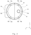
- Fig. 2 is a side view for describing a fixing part included in the fixing structure according to this embodiment.
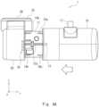
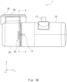
- Fig. 3 is a side view for describing a main body included in the fixing structure according to this embodiment.
- a fixing structure 1 includes a main body 10 and a fixing part 20.
- the main body 10 includes a cylindrical columnar part 11.
- the fixing part 20 includes a tubular recess 21 (see Fig. 3 ).
- the columnar part 11 of the main body 10 is fit into the recess 21 of the fixing part 20, whereby the main body 10 is fixed to the fixing part 20 (see Fig. 4C ).
- the fixing structure 1 according to this embodiment is applied to a fixing structure for fixing a vehicle image capturing apparatus. That is, in a configuration example shown in Figs. 1-3 , the main body 10 includes an image-capturing part 18 (see Fig. 2 ), and the fixing part 20 is configured to be mountable on a predetermined position (typically, a windshield or a rear glass) of the vehicle. Note that the fixing structure 1 according to this embodiment may be used for a structure other than the fixing structure for fixing the vehicle image capturing apparatus.
- the main body 10 includes the cylindrical columnar part 11.
- the columnar part 11 is provided to extend in the x-axis direction on the negative side of the x-axis direction of the main body 10.
- Positioning protrusions 12a and 12b, a plurality of first regulating protrusions 14a-14d, and a plurality of second regulating protrusions 15a-15d are formed on an outer peripheral surface of the columnar part 11.
- the positioning protrusions 12a and 12b are formed to extend in the x-axis direction on the outer peripheral surface of the columnar part 11. As shown in Fig. 2 , the positioning protrusions 12a and 12b are each located so as to be positionally shifted from each other by 180° in the circumferential direction on the outer peripheral surface of the columnar part 11.
- the positioning protrusions 12a and 12b are each configured in such a way that they can each be fit into one of a plurality of fitting grooves 22 and 23 (see Fig. 3 ) provided in the fixing part 20. That is, the positioning protrusions 12a and 12b are fit into the fitting grooves 22 and 23 of the fixing part 20, whereby an angle of the main body 10 relative to the fixing part 20 is adjusted.
- a mark 13 (see Fig. 1 ) is disposed on the front surface of the main body 10 that corresponds to at least one of the positioning protrusions 12a. By providing the mark 13, it becomes easy for a user to visually recognize the position of the positioning protrusion 12a. Accordingly, an operation of mounting the main body 10 on the fixing part 20 can be facilitated.
- Fig. 2 shows a configuration example in which the positioning protrusions 12a and 12b are located so as to be positionally shifted from each other by 180° in the circumferential direction.
- the number of positioning protrusions can be set to a desired number.
- three positioning protrusions may be located so as to be positionally shifted from each other by 120° in the circumferential direction, or four positioning protrusions may be located so as to be positionally shifted from each other by 90° in the circumferential direction.
- fitting grooves are formed in the fixing part 20 in such a way that they correspond to the positioning protrusions.
- the plurality of first regulating protrusions 14a-14d are formed in such a way that they extend in the x-axis direction on the outer peripheral surface of the columnar part 11. Further, the plurality of first regulating protrusions 14a-14d are formed on an end part side of the columnar part 11 on a side thereof where the columnar part 11 is fit into the recess 21 (the negative side of the x-axis direction). As shown in Fig. 2 , the plurality of first regulating protrusions 14a-14d are located so as to be positionally shifted from each other by 90° in the circumferential direction on the outer peripheral surface of the columnar part 11.
- the plurality of first regulating protrusions 14a-14d are formed between the positioning protrusion 12a and the positioning protrusion 12b on the outer peripheral surface of the columnar part 11.
- the first regulating protrusions 14a and 14c are formed on the positive side of the z-axis direction between the positioning protrusion 12a and the positioning protrusion 12b
- the first regulating protrusions 14b and 14d are formed on the negative side of the z-axis direction between the positioning protrusion 12a and the positioning protrusion 12b.
- the first regulating protrusions 14a-14d are configured to regulate the position of the columnar part 11 with respect to the recess 21 in such a way that the positioning protrusions 12a and 12b are fit into the predetermined fitting grooves 22 and 23 (see Fig. 3 ) when the columnar part 11 is fit into the recess 21.
- the columnar part 11 is guided in such a way that the positioning protrusions 12a and 12b are fit into the fitting grooves 22 and 23 after at least one of the plurality of first regulating protrusions 14a-14d is abut to the inner peripheral surface of the recess 21.
- the diameter of the outer peripheral surface of the columnar part 11 is smaller than the inner diameter of the recess 21. Therefore, in a state in which a part of the outer peripheral surface of the columnar part 11 directly contacts the inner surface of the recess 21, that is, in a state in which the columnar part 11 and the recess 21 are eccentric, it is possible that the fitting of the positioning protrusions 12a and 12b with the fitting grooves 22 and 23 may be inhibited.
- the first regulating protrusions 14a-14d are provided, whereby it is possible to guide the columnar part 11 in such a way that the positioning protrusions 12a and 12b are fit into the fitting grooves 22 and 23.
- the plurality of first regulating protrusions 14a-14d are configured in such a way that the height thereof from the outer peripheral surface becomes lower than that of the positioning protrusions 12a and 12b. That is, the plurality of first regulating protrusions 14a-14d are configured in such a way that gaps are formed between the top part of each of the first regulating protrusions 14a-14d and the inner peripheral surface of the recess 21 in the state in which the columnar part 11 is fit into the recess 21. In other words, the radius of the recess 21 is made greater than a value obtained by adding the height of the first regulating protrusions 14a-14d to the radius of the outer peripheral surface of the columnar part 11.
- the columnar part 11 can be easily fit into the recess 21. Further, since the first regulating protrusions 14a-14d are provided, it is possible to prevent the main body 10 from being displaced relative to the fixing part 20 after the main body 10 is fit into the fixing part 20, whereby it is possible to prevent the positioning protrusions 12a and 12b from being fit into fitting grooves 22 and 23 other than the expected ones and to fix the main body 10 to the fixing part 20 in a stable manner.
- the plurality of second regulating protrusions 15a-15d are formed on an end part side on the positive side of the x-axis direction of the columnar part 11, that is, on the positive side of the x-axis direction with respect to the plurality of first regulating protrusions 14a-14d.
- the plurality of second regulating protrusions 15a-15d have a function for regulating and stabilizing the position of the columnar part 11 with respect to the recess 21 when the columnar part 11 is fit into the recess 21.
- gaps formed between the second regulating protrusions 15a-15d and the inner peripheral surface of the recess 21 can be made small, whereby the columnar part 11 can be fixed to the recess 21 in a stable manner.
- the plurality of second regulating protrusions 15a-15d are formed to extend in the x-axis direction on the outer peripheral surface of the columnar part 11.
- the plurality of second regulating protrusions 15a-15d are located so as to be positionally shifted from each other by 90° in the circumferential direction on the outer peripheral surface of the columnar part 11.
- the second regulating protrusions 15a and 15c are formed on the positive side of the z-axis direction between the positioning protrusion 12a
- the positioning protrusion 12b and the second regulating protrusions 15b and 15d are formed on the negative side of the z-axis direction between the positioning protrusion 12a and the positioning protrusion 12b.
- the plurality of first regulating protrusions 14a-14d and the plurality of second regulating protrusions 15a-15d are formed to be aligned on one line in the x-axis direction.
- the plurality of first regulating protrusions 14a-14d and the plurality of second regulating protrusions 15a-15d may be formed in such a way that the plurality of first regulating protrusions 14a-14d and the plurality of second regulating protrusions 15a-15d are not aligned on one line in the x-axis direction, that is, in such a way that they are positionally shifted from each other in the circumferential direction of the outer peripheral surface of the columnar part 11.
- the plurality of second regulating protrusions 15a-15d have a function of regulating and stabilizing, when the columnar part 11 is fit into the recess 21, the position of the columnar part 11 with respect to the recess 21.
- the plurality of second regulating protrusions 15a-15d are configured in such a way that the height thereof from the outer peripheral surface becomes lower than that of the positioning protrusions 12a and 12b. That is, the plurality of second regulating protrusions 15a-15d are configured in such a way that gaps are formed between the top part of each of the second regulating protrusions 15a-15d and the inner peripheral surface of the recess 21 in the state in which the columnar part 11 is fit into the recess 21.
- the plurality of second regulating protrusions 15a-15d may be configured in such a way that the height thereof becomes higher than that of the plurality of first regulating protrusions 14a-14d.
- a fixed screw hole 19 is disposed on an end part on the negative side of the x-axis direction of the main body 10.
- the fixed screw hole 19 is configured to be located in a hole part 28 (see Fig. 3 ) of the fixing part 20.
- a screw is screwed into the fixed screw hole 19, whereby the main body 10 can be fixed to the fixing part 20.
- the plurality of fitting grooves 22 and 23 are disposed so as to be opposed to each other about the central axis 30.
- the fitting grooves 22 and 23 are formed in such a way that the lines that connect the respective fitting grooves 22 to the respective fitting grooves 23 are lines that pass through the central axis 30 (shown by broken lines in Fig. 3 ).
- the angle of the main body 10 relative to the fixing part 20 can be determined from among a plurality of angles about the central axis 30. In the configuration example in Fig. 3 , one of four angles 20°, 30°, 40°, and 50° with respect to a reference surface 29, which is parallel to the mounting surface 25, can be selected.
- the main body 10 is moved toward the negative side of the x-axis direction to cause the columnar part 11 of the main body 10 to be fit into the recess 21 of the fixing part 20.
- the first regulating protrusions 14a-14d regulate the position of the columnar part 11 with respect to the recess 21 in such a way that the positioning protrusions 12a and 12b are fit into the predetermined fitting grooves 22 and 23 when the columnar part 11 is fit into the recess 21.
- the positions of the positioning protrusions 12a and 12b of the main body 10 may be deviated with respect to the fitting grooves 22 and 23 of the fixing part 20.
- the diameter of the columnar part 11 of the main body 10 is smaller than the diameter of the recess 21 of the fixing part 20.
- the plurality of first regulating protrusions 14a-14d are provided in the main body 10.
- the plurality of first regulating protrusions 14a-14d are provided in the main body 10 when the columnar part 11 is fit into the recess 21, the position of the columnar part 11 with respect to the recess 21 is regulated. Accordingly, it is possible to prevent the positions of the positioning protrusions 12a and 12b from being deviated relative to the fitting grooves 22 and 23.
- the main body 10 is moved toward the negative side of the x-axis direction to cause the columnar part 11 of the main body 10 to be fit into the recess 21 of the fixing part 20. Consequently, the main body 10 is fixed to the fixing part 20.
- the fixing part 20 to which the main body 10 is fixed is mounted on a windshield (not shown). Specifically, by mounting the mounting surface 25 of the fixing part 20 on the windshield of the vehicle by using the adhesive member 26, the fixing part 20 to which the main body 10 is fixed is fixed to the windshield.
- the positioning protrusions 12a and 12b are fit into the fitting grooves 22 and 23 of the fixing part 20, whereby the angle of the main body 10 relative to the fixing part 20 is adjusted.
- the configuration example shown in Fig. 5 shows an example in which the main body 10 is mounted on the fixing part 20 at an angle of 30° relative to the reference surface 29 (see Fig. 3 ), which is parallel to the mounting surface 25. Further, the plurality of second regulating protrusions 15a-15d are disposed inside the recess 21. It is therefore possible to prevent the main body 10 from being displaced with respect to the fixing part 20. Therefore, the main body 10 can be fixed to the fixing part 20 in a stable manner.
- the plurality of second regulating protrusions 15a-15d may each have a lying shape in a circumferential direction of the outer peripheral surface of the columnar part 11 in a cross section perpendicular to the central axis 30, that is, a cross section cut in the yz-plane.
- the cross-sectional shape of the second regulating protrusions 15a-15d is formed to be a lying shape, in other words, a flat shape, or more specifically, a mountainous shape that is biased toward one side, whereby the strength of the second regulating protrusions 15a-15d can be improved.
- the plurality of first regulating protrusions 14a-14d may also each have a lying shape in the circumferential direction of the outer peripheral surface of the columnar part 11 in a cross section cut in the yz-plane.
- the cross-sectional shape of the second regulating protrusions 15a-15d is formed to be a lying shape in the y-axis direction, whereby the main body 10 can be easily manufactured. That is, the surface on the positive side of the z-axis direction of the second regulating protrusions 15a and 15c (a surface that forms the second regulating protrusions) is made to be parallel to the xy-plane and the surface on the negative side of the z-axis direction of the second regulating protrusions 15b and 15d (a surface that forms the second regulating protrusions) is made to be parallel to the xy-plane.
- the cross-sectional shape of the plurality of first regulating protrusions 14a-14d may be a lying shape in the y-axis direction.
- the fixing structure 1 includes the main body 10 including the cylindrical columnar part 11, and the fixing part 20 including the tubular recess 21 into which the columnar part 11 is fit.
- the fitting grooves 22 and 23 are formed at predetermined angular intervals at positions opposed to each other about the central axis of the recess 21 on the inner peripheral surface of the recess 21.
- the positioning protrusions 12a and 12b for positioning, which can be fit into the fitting grooves 22 and 23, and the plurality of first regulating protrusions 14a-14d whose height is lower than that of the positioning protrusions 12a and 12b are formed on the outer peripheral surface of the columnar part 11.
- the fixing structure 1 is configured to be able to adjust the angle of the main body 10 relative to the fixing part 20 by selecting the fitting grooves 22 and 23 into which the positioning protrusions 12a and 12b of the columnar part 11 are fit. Then, the first regulating protrusions 14a-14d are configured to regulate the position of the columnar part 11 with respect to the recess 21 in such a way that the positioning protrusions 12a and 12b are fit into the predetermined fitting grooves 22 and 23 when the columnar part 11 is fit into the recess 21.
- the plurality of first regulating protrusions 14a-14d are provided in the main body 10, when the columnar part 11 is fit into the recess 21, the position of the columnar part 11 with respect to the recess 21 is regulated. It is therefore possible to prevent the positions of the positioning protrusions 12a and 12b from being deviated relative to the fitting grooves 22 and 23. In other words, when the columnar part 11 is fit into the recess 21, the columnar part 11 is guided in such a way that the positioning protrusions 12a and 12b are fit into the fitting grooves 22 and 23 after at least one of the plurality of first regulating protrusions 14a-14d is abut to the inner peripheral surface of the recess 21. Accordingly, according to this embodiment, it is possible to provide a fixing structure capable of facilitating the operation of mounting the image capturing apparatus on the vehicle while adjusting the mounting angle.
- the fixing structure according to the present disclosure can be widely used as a structure for mounting an image capturing apparatus such as a dashboard camera on a vehicle.
Landscapes
- Engineering & Computer Science (AREA)
- General Engineering & Computer Science (AREA)
- Physics & Mathematics (AREA)
- General Physics & Mathematics (AREA)
- Mechanical Engineering (AREA)
- Connection Of Plates (AREA)
Abstract
Description
- The present disclosure relates to a fixing structure.
- When an image capturing apparatus such as a dashboard camera is mounted on each one of different vehicles, it is required to adjust a mounting angle for each of the vehicle models since a condition of a mounting position differs from one vehicle to another vehicle. For this reason, a fixing structure capable of adjusting the mounting angle is required.
-
Patent Literature 1 discloses an opening/closing mechanism including: a hollow cylindrical bearing body, a plurality of spline-shaped grooves being formed on an inner wall of the hollow interior thereof; a hollow cylindrical slider that is inserted into the bearing body and includes spline-shaped projections engaged with the grooves of the bearing body formed on an outer peripheral surface of the hollow cylindrical slider; and a shaft body that is inserted into the slider and includes projections engaged with the grooves of the slider formed on a part of an outer peripheral surface of the shaft body. - [Patent Literature 1]
Japanese Unexamined Patent Application Publication No. H08-93303 - As described in the background art, when an image capturing apparatus such as a dashboard camera is mounted on a vehicle, it is required to mount the image capturing apparatus on the vehicle while adjusting a mounting angle for each vehicle model since a condition of a mounting position differs from one vehicle to another vehicle. For example, since the angle of the windshield differs from one vehicle to another vehicle, each time the image capturing apparatus is mounted on the windshield of a vehicle, it is required to adjust the mounting angle for this vehicle model to make sure that an image capturing direction of the image capturing apparatus faces an appropriate direction.
- However, there is a problem that an operation of mounting the image capturing apparatus on each vehicle while adjusting the mounting angle for each vehicle model is complicated for a worker. Therefore, a fixing structure capable of facilitating the operation of mounting the image capturing apparatus on each vehicle while adjusting the mounting angle has been required.
- In view of the aforementioned problem, an object of the present disclosure is to provide a fixing structure capable of facilitating an operation of mounting an image capturing apparatus on a vehicle while adjusting a mounting angle.
- A fixing structure according to the present disclosure includes: a main body including a cylindrical columnar part; and a fixing part including a tubular recess into which the columnar part is fit. Fitting grooves are formed on an inner peripheral surface of the recess at predetermined angular intervals, positioning protrusions for positioning, which can be fit into the fitting grooves, and a plurality of first regulating protrusions whose height is lower than that of the positioning protrusions are formed on an outer peripheral surface of the columnar part, an angle of the main body relative to the fixing part is configured to be adjustable by selecting the fitting grooves into which the positioning protrusions of the columnar part are fit, and the first regulating protrusions regulate a position of the columnar part relative to the recess in such a way that the positioning protrusions are fit into the predetermined fitting grooves when the columnar part is fit into the recess.
- According to the present disclosure, it is possible to provide a fixing structure capable of facilitating an operation of mounting an image capturing apparatus on a vehicle while adjusting a mounting angle.
-
-
Fig. 1 is a front view for describing a fixing structure according to an embodiment. -
Fig. 2 is a side view for describing a main body included in the fixing structure according to the embodiment. -
Fig. 3 is a side view for describing a fixing part included in the fixing structure according to the embodiment. -
Fig. 4A is a front view for describing an operation when the main body is mounted on the fixing part. -
Fig. 4B is a front view for describing an operation when the main body is mounted on the fixing part. -
Fig. 4C is a front view for describing an operation when the main body is mounted on the fixing part. -
Fig. 5 is a cross-sectional view taken along the line V-V ofFig. 4C . - Hereinafter, with reference to the drawings, an embodiment will be described.
-
Fig. 1 is a front view for describing a fixing structure according to this embodiment.Fig. 2 is a side view for describing a fixing part included in the fixing structure according to this embodiment.Fig. 3 is a side view for describing a main body included in the fixing structure according to this embodiment. - As shown in
Fig. 1 , afixing structure 1 according to this embodiment includes amain body 10 and afixing part 20. Themain body 10 includes a cylindricalcolumnar part 11. Thefixing part 20 includes a tubular recess 21 (seeFig. 3 ). In thefixing structure 1 according to this embodiment, thecolumnar part 11 of themain body 10 is fit into therecess 21 of thefixing part 20, whereby themain body 10 is fixed to the fixing part 20 (seeFig. 4C ). - Hereinafter, as one example, a case where the
fixing structure 1 according to this embodiment is applied to a fixing structure for fixing a vehicle image capturing apparatus will be described. That is, in a configuration example shown inFigs. 1-3 , themain body 10 includes an image-capturing part 18 (seeFig. 2 ), and thefixing part 20 is configured to be mountable on a predetermined position (typically, a windshield or a rear glass) of the vehicle. Note that thefixing structure 1 according to this embodiment may be used for a structure other than the fixing structure for fixing the vehicle image capturing apparatus. - As shown in
Figs. 1 and2 , themain body 10 includes the cylindricalcolumnar part 11. Thecolumnar part 11 is provided to extend in the x-axis direction on the negative side of the x-axis direction of themain body 10. Positioningprotrusions protrusions 14a-14d, and a plurality of second regulatingprotrusions 15a-15d are formed on an outer peripheral surface of thecolumnar part 11. - The
positioning protrusions columnar part 11. As shown inFig. 2 , thepositioning protrusions columnar part 11. Thepositioning protrusions fitting grooves 22 and 23 (seeFig. 3 ) provided in thefixing part 20. That is, thepositioning protrusions fitting grooves fixing part 20, whereby an angle of themain body 10 relative to thefixing part 20 is adjusted. A mark 13 (seeFig. 1 ) is disposed on the front surface of themain body 10 that corresponds to at least one of thepositioning protrusions 12a. By providing themark 13, it becomes easy for a user to visually recognize the position of thepositioning protrusion 12a. Accordingly, an operation of mounting themain body 10 on thefixing part 20 can be facilitated. -
Fig. 2 shows a configuration example in which thepositioning protrusions fixing part 20 in such a way that they correspond to the positioning protrusions. - As shown in
Figs. 1 and2 , the plurality of first regulatingprotrusions 14a-14d are formed in such a way that they extend in the x-axis direction on the outer peripheral surface of thecolumnar part 11. Further, the plurality of first regulatingprotrusions 14a-14d are formed on an end part side of thecolumnar part 11 on a side thereof where thecolumnar part 11 is fit into the recess 21 (the negative side of the x-axis direction). As shown inFig. 2 , the plurality of first regulatingprotrusions 14a-14d are located so as to be positionally shifted from each other by 90° in the circumferential direction on the outer peripheral surface of thecolumnar part 11. At this time, the plurality of first regulatingprotrusions 14a-14d are formed between thepositioning protrusion 12a and thepositioning protrusion 12b on the outer peripheral surface of thecolumnar part 11. Specifically, the first regulatingprotrusions positioning protrusion 12a and thepositioning protrusion 12b, and the first regulatingprotrusions positioning protrusion 12a and thepositioning protrusion 12b. - The first regulating
protrusions 14a-14d are configured to regulate the position of thecolumnar part 11 with respect to therecess 21 in such a way that thepositioning protrusions predetermined fitting grooves 22 and 23 (seeFig. 3 ) when thecolumnar part 11 is fit into therecess 21. In other words, when thecolumnar part 11 is fit into therecess 21, thecolumnar part 11 is guided in such a way that thepositioning protrusions fitting grooves protrusions 14a-14d is abut to the inner peripheral surface of therecess 21. That is, the diameter of the outer peripheral surface of thecolumnar part 11 is smaller than the inner diameter of therecess 21. Therefore, in a state in which a part of the outer peripheral surface of thecolumnar part 11 directly contacts the inner surface of therecess 21, that is, in a state in which thecolumnar part 11 and therecess 21 are eccentric, it is possible that the fitting of thepositioning protrusions fitting grooves protrusions 14a-14d are provided, whereby it is possible to guide thecolumnar part 11 in such a way that thepositioning protrusions fitting grooves - As shown in
Fig. 2 , the plurality of first regulatingprotrusions 14a-14d are configured in such a way that the height thereof from the outer peripheral surface becomes lower than that of thepositioning protrusions protrusions 14a-14d are configured in such a way that gaps are formed between the top part of each of the first regulatingprotrusions 14a-14d and the inner peripheral surface of therecess 21 in the state in which thecolumnar part 11 is fit into therecess 21. In other words, the radius of therecess 21 is made greater than a value obtained by adding the height of the first regulatingprotrusions 14a-14d to the radius of the outer peripheral surface of thecolumnar part 11. Consequently, thecolumnar part 11 can be easily fit into therecess 21. Further, since the first regulatingprotrusions 14a-14d are provided, it is possible to prevent themain body 10 from being displaced relative to the fixingpart 20 after themain body 10 is fit into the fixingpart 20, whereby it is possible to prevent thepositioning protrusions fitting grooves main body 10 to the fixingpart 20 in a stable manner. - As shown in
Fig. 1 , the plurality ofsecond regulating protrusions 15a-15d are formed on an end part side on the positive side of the x-axis direction of thecolumnar part 11, that is, on the positive side of the x-axis direction with respect to the plurality of first regulatingprotrusions 14a-14d. The plurality ofsecond regulating protrusions 15a-15d have a function for regulating and stabilizing the position of thecolumnar part 11 with respect to therecess 21 when thecolumnar part 11 is fit into therecess 21. In other words, gaps formed between thesecond regulating protrusions 15a-15d and the inner peripheral surface of therecess 21 can be made small, whereby thecolumnar part 11 can be fixed to therecess 21 in a stable manner. The plurality ofsecond regulating protrusions 15a-15d are formed to extend in the x-axis direction on the outer peripheral surface of thecolumnar part 11. - As shown in
Fig. 2 , the plurality ofsecond regulating protrusions 15a-15d are located so as to be positionally shifted from each other by 90° in the circumferential direction on the outer peripheral surface of thecolumnar part 11. Specifically, thesecond regulating protrusions protrusion 12a, and thepositioning protrusion 12b and the second regulatingprotrusions protrusion 12a and thepositioning protrusion 12b. - In the configuration examples shown in
Figs. 1 and2 , the plurality of first regulatingprotrusions 14a-14d and the plurality ofsecond regulating protrusions 15a-15d are formed to be aligned on one line in the x-axis direction. Alternatively, in this embodiment, the plurality of first regulatingprotrusions 14a-14d and the plurality ofsecond regulating protrusions 15a-15d may be formed in such a way that the plurality of first regulatingprotrusions 14a-14d and the plurality ofsecond regulating protrusions 15a-15d are not aligned on one line in the x-axis direction, that is, in such a way that they are positionally shifted from each other in the circumferential direction of the outer peripheral surface of thecolumnar part 11. - The plurality of
second regulating protrusions 15a-15d have a function of regulating and stabilizing, when thecolumnar part 11 is fit into therecess 21, the position of thecolumnar part 11 with respect to therecess 21. As shown inFig. 2 , the plurality ofsecond regulating protrusions 15a-15d are configured in such a way that the height thereof from the outer peripheral surface becomes lower than that of thepositioning protrusions second regulating protrusions 15a-15d are configured in such a way that gaps are formed between the top part of each of thesecond regulating protrusions 15a-15d and the inner peripheral surface of therecess 21 in the state in which thecolumnar part 11 is fit into therecess 21. Further, as shown inFig. 2 , the plurality ofsecond regulating protrusions 15a-15d may be configured in such a way that the height thereof becomes higher than that of the plurality of first regulatingprotrusions 14a-14d. With this configuration, when thecolumnar part 11 is fit into therecess 21, the gaps formed between thesecond regulating protrusions 15a-15d and the inner peripheral surface of therecess 21 can be made small, whereby it is possible to fix thecolumnar part 11 to therecess 21 more stably. - As shown in
Fig. 2 , the mage-capturingpart 18 is disposed on the positive side of the y-axis direction of themain body 10. The image-capturingpart 18, which can be constituted using a camera, is configured to be able to capture a video image on the positive side of the y-axis direction. As shown inFig. 1 , acable 17 is disposed on the positive side of the z-axis direction of themain body 10. For example, thecable 17 is a power supply cable, and power is supplied to themain body 10 via the power supply cable. - As shown in
Fig. 2 , a fixedscrew hole 19 is disposed on an end part on the negative side of the x-axis direction of themain body 10. The fixedscrew hole 19 is configured to be located in a hole part 28 (seeFig. 3 ) of the fixingpart 20. For example, after themain body 10 is mounted on the fixingpart 20, a screw is screwed into the fixedscrew hole 19, whereby themain body 10 can be fixed to the fixingpart 20. - As shown in
Figs. 1 and3 , the fixingpart 20 includes a mountingsurface 25. Anadhesive member 26 is disposed on the mountingsurface 25. When the fixingpart 20 is mounted on the windshield of the vehicle, the mountingsurface 25 of the fixingpart 20 is mounted on the windshield of the vehicle by using theadhesive member 26. Accordingly, the fixingpart 20 can be fixed to the windshield of the vehicle. - Further, as shown in
Figs. 1 and3 , the fixingpart 20 includes thetubular recess 21. Thecolumnar part 11 of themain body 10 is fit into thetubular recess 21. As shown inFig. 3 , thefitting grooves recess 21, at predetermined angular intervals at positions opposed to each other about acentral axis 30 of therecess 21. In other words, thefitting grooves central axis 30 of therecess 21. Then, the fixingstructure 1 according to this embodiment is able to adjust the angle of themain body 10 relative to the fixingpart 20 by selecting thefitting grooves positioning protrusions columnar part 11 are fit. - That is, as shown in
Fig. 3 , the plurality offitting grooves central axis 30. Specifically, thefitting grooves fitting grooves 22 to the respectivefitting grooves 23 are lines that pass through the central axis 30 (shown by broken lines inFig. 3 ). In this embodiment, by selecting the combination of thefitting grooves positioning protrusions columnar part 11 are fit, the angle of themain body 10 relative to the fixingpart 20 can be determined from among a plurality of angles about thecentral axis 30. In the configuration example inFig. 3 , one of fourangles 20°, 30°, 40°, and 50° with respect to areference surface 29, which is parallel to the mountingsurface 25, can be selected. -
Marks 24 are disposed on a front surface of the fixingpart 20 corresponding to the positions where the plurality offitting grooves 22 are formed. By providing themarks 24, the user can visually recognize the positions of thefitting grooves 22 easily. Accordingly, an operation of mounting themain body 10 on the fixingpart 20 can be facilitated. In this embodiment, the mountingsurface 25 of the fixingpart 20 is mounted on the windshield. Therefore, themarks 24 are provided on the side of thefitting grooves 22, not on the side of thefitting grooves 23, so that the user can visually recognize the positions of thefitting grooves 22 when the user fixes themain body 10 to the fixingpart 20. - Next, with reference to
Figs. 4A-4C , an operation when themain body 10 is mounted on the fixingpart 20 will be described. First, as shown inFig. 4A , the mounting angle when themain body 10 is mounted on the fixingpart 20 is determined. Specifically,fitting grooves positioning protrusions main body 10 are fit are determined from among thefitting grooves part 20, and thus the angle at which themain body 10 is mounted on the fixingpart 20 is determined. At this time, by using themarks 24 provided in the fixingpart 20 and themark 13 provided in themain body 10, the positions of thepositioning protrusions main body 10 and thefitting grooves part 20 are determined. InFigs. 4A-4C , themarks Fig. 2 ) is not shown inFigs. 4A-4C . That is, since the image-capturingpart 18 is mounted in such a way that it faces outside of the vehicle, themarks main body 10 and is present on the inner side of the vehicle can see themarks marks part 18 are provided on the same side. - Then, as shown in
Fig. 4B , themain body 10 is moved toward the negative side of the x-axis direction to cause thecolumnar part 11 of themain body 10 to be fit into therecess 21 of the fixingpart 20. At this time, the first regulatingprotrusions 14a-14d regulate the position of thecolumnar part 11 with respect to therecess 21 in such a way that thepositioning protrusions fitting grooves columnar part 11 is fit into therecess 21. - When, for example, the direction in which the
main body 10 moves becomes oblique relative to the x-axis direction, it is possible that the positions of thepositioning protrusions main body 10 may be deviated with respect to thefitting grooves part 20. Further, the diameter of thecolumnar part 11 of themain body 10 is smaller than the diameter of therecess 21 of the fixingpart 20. Therefore, if the central axis of thecolumnar part 11 of themain body 10 and the central axis of therecess 21 of the fixingpart 20 are deviated from each other, it is possible, for example, that onepositioning protrusion 12b may be fit into the intended fittinggroove 23, whereas theother positioning protrusion 12a may be fit into a groove that is next to the intended fittinggroove 22. - In order to solve the aforementioned problem, in this embodiment, the plurality of first regulating
protrusions 14a-14d are provided in themain body 10. In this embodiment, since the plurality of first regulatingprotrusions 14a-14d are provided in themain body 10, when thecolumnar part 11 is fit into therecess 21, the position of thecolumnar part 11 with respect to therecess 21 is regulated. Accordingly, it is possible to prevent the positions of thepositioning protrusions fitting grooves columnar part 11 of themain body 10 and the central axis of therecess 21 of the fixingpart 20 are deviated from each other and thepositioning protrusions fitting grooves columnar part 11 is fit into therecess 21, at least one of the plurality of first regulatingprotrusions 14a-14d is abut to the inner peripheral surface of therecess 21, which suppresses eccentricity of thecolumnar part 11 and therecess 21, whereby it is possible to guide thecolumnar part 11 in such a way that thepositioning protrusions fitting grooves - After that, as shown in
Fig. 4C , themain body 10 is moved toward the negative side of the x-axis direction to cause thecolumnar part 11 of themain body 10 to be fit into therecess 21 of the fixingpart 20. Consequently, themain body 10 is fixed to the fixingpart 20. After that, the fixingpart 20 to which themain body 10 is fixed is mounted on a windshield (not shown). Specifically, by mounting the mountingsurface 25 of the fixingpart 20 on the windshield of the vehicle by using theadhesive member 26, the fixingpart 20 to which themain body 10 is fixed is fixed to the windshield. - In this embodiment, as shown in the cross-sectional view in
Fig. 5 , thepositioning protrusions fitting grooves part 20, whereby the angle of themain body 10 relative to the fixingpart 20 is adjusted. The configuration example shown inFig. 5 shows an example in which themain body 10 is mounted on the fixingpart 20 at an angle of 30° relative to the reference surface 29 (seeFig. 3 ), which is parallel to the mountingsurface 25. Further, the plurality ofsecond regulating protrusions 15a-15d are disposed inside therecess 21. It is therefore possible to prevent themain body 10 from being displaced with respect to the fixingpart 20. Therefore, themain body 10 can be fixed to the fixingpart 20 in a stable manner. - Further, as shown in
Fig. 5 , the plurality ofsecond regulating protrusions 15a-15d may each have a lying shape in a circumferential direction of the outer peripheral surface of thecolumnar part 11 in a cross section perpendicular to thecentral axis 30, that is, a cross section cut in the yz-plane. In this manner, the cross-sectional shape of thesecond regulating protrusions 15a-15d is formed to be a lying shape, in other words, a flat shape, or more specifically, a mountainous shape that is biased toward one side, whereby the strength of thesecond regulating protrusions 15a-15d can be improved. The plurality of first regulatingprotrusions 14a-14d may also each have a lying shape in the circumferential direction of the outer peripheral surface of thecolumnar part 11 in a cross section cut in the yz-plane. - Further, in this embodiment, the cross-sectional shape of the
second regulating protrusions 15a-15d is formed to be a lying shape in the y-axis direction, whereby themain body 10 can be easily manufactured. That is, the surface on the positive side of the z-axis direction of thesecond regulating protrusions protrusions main body 10 is injection-molded using two molds, these two molds can be pulled out both on the positive side and the negative side in the y-axis direction, whereby themain body 10 can be easily manufactured. Regarding the plurality of first regulatingprotrusions 14a-14d as well, the cross-sectional shape of the plurality of first regulatingprotrusions 14a-14d may be a lying shape in the y-axis direction. - As described above, the fixing
structure 1 according to this embodiment includes themain body 10 including the cylindricalcolumnar part 11, and the fixingpart 20 including thetubular recess 21 into which thecolumnar part 11 is fit. Thefitting grooves recess 21 on the inner peripheral surface of therecess 21. Thepositioning protrusions fitting grooves protrusions 14a-14d whose height is lower than that of thepositioning protrusions columnar part 11. Further, the fixingstructure 1 according to this embodiment is configured to be able to adjust the angle of themain body 10 relative to the fixingpart 20 by selecting thefitting grooves positioning protrusions columnar part 11 are fit. Then, the first regulatingprotrusions 14a-14d are configured to regulate the position of thecolumnar part 11 with respect to therecess 21 in such a way that thepositioning protrusions fitting grooves columnar part 11 is fit into therecess 21. - As described above, in this embodiment, since the plurality of first regulating
protrusions 14a-14d are provided in themain body 10, when thecolumnar part 11 is fit into therecess 21, the position of thecolumnar part 11 with respect to therecess 21 is regulated. It is therefore possible to prevent the positions of thepositioning protrusions fitting grooves columnar part 11 is fit into therecess 21, thecolumnar part 11 is guided in such a way that thepositioning protrusions fitting grooves protrusions 14a-14d is abut to the inner peripheral surface of therecess 21. Accordingly, according to this embodiment, it is possible to provide a fixing structure capable of facilitating the operation of mounting the image capturing apparatus on the vehicle while adjusting the mounting angle. - While the present invention has been described in view of the aforementioned embodiment, the present invention is not limited to the configuration in the above-described embodiment. As a matter of course, the present invention includes various changes, modifications, and combinations that one skilled in the art might make within the scope of the invention as set forth in claims of the present application.
- This application is based upon and claims the benefit of priority from
Japanese patent application No. 2022-199476, filed on December 14, 2022 - The fixing structure according to the present disclosure can be widely used as a structure for mounting an image capturing apparatus such as a dashboard camera on a vehicle.
-
- 10 Main Body
- 11 Columnar Part
- 12a, 12b Positioning Protrusion
- 14a, 14b, 14c, 14d First Regulating Protrusion
- 15a, 15b, 15c, 15d Second Regulating Protrusion
- 20 Fixing Part
- 21 Recess
- 22, 23 Fitting Groove
Claims (9)
- A fixing structure comprising:a main body including a cylindrical columnar part; anda fixing part including a tubular recess into which the columnar part is fit, whereinfitting grooves are formed on an inner peripheral surface of the recess at predetermined angular intervals,positioning protrusions for positioning, which can be fit into the fitting grooves, and a plurality of first regulating protrusions whose height is lower than that of the positioning protrusions are formed on an outer peripheral surface of the columnar part,an angle of the main body relative to the fixing part is configured to be adjustable by selecting the fitting grooves into which the positioning protrusions of the columnar part are fit, andthe first regulating protrusions regulate a position of the columnar part relative to the recess in such a way that the positioning protrusions are fit into the predetermined fitting grooves when the columnar part is fit into the recess.
- The fixing structure according to claim 1, wherein the first regulating protrusions regulate eccentricity of the main body and the fixing part when the columnar part is fit into the recess.
- The fixing structure according to claim 1 or 2, wherein gaps are formed between a top part of each of the first regulating protrusions and the inner peripheral surface of the recess in a state in which the columnar part is fit into the recess.
- The fixing structure according to claim 1 or 2, wherein a radius of the recess is greater than a value obtained by adding the height of the first regulating protrusion to a radius on the outer peripheral surface of the columnar part.
- The fixing structure according to claim 1 or 2, wherein the first regulating protrusions each have a lying shape in a circumferential direction of the outer peripheral surface of the columnar part in a cross section perpendicular to a central axis of the columnar part.
- The fixing structure according to claim 1 or 2, wherein a surface that forms the first regulating protrusions coincides with a mold removal direction when the main body is molded.
- The fixing structure according to claim 1 or 2, wherein marks are formed, on an outer peripheral surface of the fixing part, at positions that correspond to the fitting grooves formed on the inner peripheral surface of the recess.
- The fixing structure according to claim 1 or 2, whereinthe first regulating protrusions are formed on a first end part side of the columnar part, which is a side of the columnar part fit into the recess, anda second regulating protrusion for regulating and stabilizing a position of the columnar part relative to the recess when the columnar part is fit into the recess is further formed on a second end part side of the columnar part, which is a side opposite to the first end part side.
- The fixing structure according to claim 1 or 2, whereinthe first regulating protrusions are formed on a first end part side of the columnar part, which is a side of the columnar part fit into the recess,a second regulating protrusion for regulating and stabilizing a position of the columnar part relative to the recess when the columnar part is fit into the recess is further formed on a second end part side of the columnar part, which is a side opposite to the first end part side, andthe second regulating protrusion is configured to be higher than the first regulating protrusion.
Applications Claiming Priority (2)
| Application Number | Priority Date | Filing Date | Title |
|---|---|---|---|
| JP2022199476 | 2022-12-14 | ||
| PCT/JP2023/038564 WO2024127825A1 (en) | 2022-12-14 | 2023-10-25 | Fixing structure |
Publications (2)
| Publication Number | Publication Date |
|---|---|
| EP4564091A1 true EP4564091A1 (en) | 2025-06-04 |
| EP4564091A4 EP4564091A4 (en) | 2025-12-31 |
Family
ID=91484817
Family Applications (1)
| Application Number | Title | Priority Date | Filing Date |
|---|---|---|---|
| EP23903123.0A Pending EP4564091A4 (en) | 2022-12-14 | 2023-10-25 | FASTENING STRUCTURE |
Country Status (5)
| Country | Link |
|---|---|
| US (1) | US20250199385A1 (en) |
| EP (1) | EP4564091A4 (en) |
| JP (1) | JPWO2024127825A1 (en) |
| CN (1) | CN119604815A (en) |
| WO (1) | WO2024127825A1 (en) |
Family Cites Families (6)
| Publication number | Priority date | Publication date | Assignee | Title |
|---|---|---|---|---|
| US3924775A (en) * | 1973-06-04 | 1975-12-09 | Weston Instruments Inc | Positively lockable angularly adjustable handle |
| JP2601215B2 (en) | 1994-09-27 | 1997-04-16 | 日本電気株式会社 | Opening and closing mechanism |
| JP3029339U (en) * | 1996-03-22 | 1996-09-27 | ヤック株式会社 | CCD camera mounting structure |
| JP5515176B2 (en) * | 2010-05-21 | 2014-06-11 | 古河電工パワーシステムズ株式会社 | Connectors and connector sets |
| CN102042467B (en) * | 2010-12-31 | 2013-01-09 | 鸿富锦精密工业(深圳)有限公司 | Multi-angle positioning bracket |
| CN213109224U (en) * | 2020-09-30 | 2021-05-04 | 深圳歌诗特科技有限公司 | Driving shooting recording device |
-
2023
- 2023-10-25 JP JP2024564200A patent/JPWO2024127825A1/ja active Pending
- 2023-10-25 EP EP23903123.0A patent/EP4564091A4/en active Pending
- 2023-10-25 CN CN202380055694.6A patent/CN119604815A/en active Pending
- 2023-10-25 WO PCT/JP2023/038564 patent/WO2024127825A1/en not_active Ceased
-
2025
- 2025-03-04 US US19/070,084 patent/US20250199385A1/en active Pending
Also Published As
| Publication number | Publication date |
|---|---|
| WO2024127825A1 (en) | 2024-06-20 |
| JPWO2024127825A1 (en) | 2024-06-20 |
| CN119604815A (en) | 2025-03-11 |
| EP4564091A4 (en) | 2025-12-31 |
| US20250199385A1 (en) | 2025-06-19 |
Similar Documents
| Publication | Publication Date | Title |
|---|---|---|
| CN112415830B (en) | Optical unit with jitter correction function | |
| EP1602117B2 (en) | Automatic vehicle exterior light control system assemblies | |
| EP2891029B1 (en) | Friction hinge system | |
| EP1701191A2 (en) | Lens barrel mount | |
| US11567339B2 (en) | Optical unit with shake correction function and method of producing optical unit with shake correction function | |
| US8414136B2 (en) | Vehicle mirror apparatus | |
| US20180111557A1 (en) | Electric retractable view device for vehicle | |
| US9395552B2 (en) | Blur correction device, and lens barrel provided with blur correction device, and camera system | |
| EP3574642B1 (en) | Modular optical recording system | |
| EP4564091A1 (en) | Fixing structure | |
| US11254264B2 (en) | Sensor assembling structure for rotary mounting-type windshield mounted inner mirror for vehicle | |
| US11731559B2 (en) | Mounting structure and mounting base for rotary mounting-type windshield mounted in-vehicle device | |
| US20180281682A1 (en) | Shaft for retractable view device for vehicle and electric retracting unit for electric retractable view device for vehicle | |
| JP2010083464A (en) | In-vehicle device and holding member | |
| US7065295B2 (en) | Apparatus for driving lens in camera | |
| US6709159B2 (en) | Bearing structure | |
| US10606023B2 (en) | Lens barrel | |
| EP3454540A1 (en) | Imaging device | |
| EP3988983B1 (en) | Camera assembly comprising a rotation blocking pin | |
| EP3835134B1 (en) | Attachment arrangement for a camera module at a vehicle | |
| EP1923874A1 (en) | Optical pickup guide mechanism | |
| JP2005224056A (en) | Vibration damping mounting structure for motor | |
| JP2014127930A (en) | On-vehicle camera device | |
| EP2045658A1 (en) | Lens device | |
| JPH1166913A (en) | Optical axis adjustment device for vehicle lighting |
Legal Events
| Date | Code | Title | Description |
|---|---|---|---|
| STAA | Information on the status of an ep patent application or granted ep patent |
Free format text: STATUS: THE INTERNATIONAL PUBLICATION HAS BEEN MADE |
|
| PUAI | Public reference made under article 153(3) epc to a published international application that has entered the european phase |
Free format text: ORIGINAL CODE: 0009012 |
|
| STAA | Information on the status of an ep patent application or granted ep patent |
Free format text: STATUS: REQUEST FOR EXAMINATION WAS MADE |
|
| 17P | Request for examination filed |
Effective date: 20250227 |
|
| AK | Designated contracting states |
Kind code of ref document: A1 Designated state(s): AL AT BE BG CH CY CZ DE DK EE ES FI FR GB GR HR HU IE IS IT LI LT LU LV MC ME MK MT NL NO PL PT RO RS SE SI SK SM TR |
|
| A4 | Supplementary search report drawn up and despatched |
Effective date: 20251202 |
|
| RIC1 | Information provided on ipc code assigned before grant |
Ipc: G03B 17/56 20210101AFI20251126BHEP Ipc: B60R 11/02 20060101ALI20251126BHEP Ipc: F16B 7/20 20060101ALI20251126BHEP Ipc: G03B 15/00 20210101ALI20251126BHEP Ipc: H04N 23/51 20230101ALI20251126BHEP Ipc: F16M 11/10 20060101ALI20251126BHEP Ipc: F16M 13/02 20060101ALI20251126BHEP |
|
| DAV | Request for validation of the european patent (deleted) | ||
| DAX | Request for extension of the european patent (deleted) |