EP4564043A1 - Hybrid quadrature receive array - Google Patents
Hybrid quadrature receive array Download PDFInfo
- Publication number
- EP4564043A1 EP4564043A1 EP24216217.0A EP24216217A EP4564043A1 EP 4564043 A1 EP4564043 A1 EP 4564043A1 EP 24216217 A EP24216217 A EP 24216217A EP 4564043 A1 EP4564043 A1 EP 4564043A1
- Authority
- EP
- European Patent Office
- Prior art keywords
- antenna
- signal
- receiver
- clock signal
- phased array
- Prior art date
- Legal status (The legal status is an assumption and is not a legal conclusion. Google has not performed a legal analysis and makes no representation as to the accuracy of the status listed.)
- Pending
Links
Images




Classifications
-
- G—PHYSICS
- G01—MEASURING; TESTING
- G01S—RADIO DIRECTION-FINDING; RADIO NAVIGATION; DETERMINING DISTANCE OR VELOCITY BY USE OF RADIO WAVES; LOCATING OR PRESENCE-DETECTING BY USE OF THE REFLECTION OR RERADIATION OF RADIO WAVES; ANALOGOUS ARRANGEMENTS USING OTHER WAVES
- G01S7/00—Details of systems according to groups G01S13/00, G01S15/00, G01S17/00
- G01S7/02—Details of systems according to groups G01S13/00, G01S15/00, G01S17/00 of systems according to group G01S13/00
- G01S7/35—Details of non-pulse systems
- G01S7/352—Receivers
- G01S7/358—Receivers using I/Q processing
-
- G—PHYSICS
- G01—MEASURING; TESTING
- G01S—RADIO DIRECTION-FINDING; RADIO NAVIGATION; DETERMINING DISTANCE OR VELOCITY BY USE OF RADIO WAVES; LOCATING OR PRESENCE-DETECTING BY USE OF THE REFLECTION OR RERADIATION OF RADIO WAVES; ANALOGOUS ARRANGEMENTS USING OTHER WAVES
- G01S7/00—Details of systems according to groups G01S13/00, G01S15/00, G01S17/00
- G01S7/02—Details of systems according to groups G01S13/00, G01S15/00, G01S17/00 of systems according to group G01S13/00
- G01S7/35—Details of non-pulse systems
- G01S7/352—Receivers
-
- G—PHYSICS
- G01—MEASURING; TESTING
- G01S—RADIO DIRECTION-FINDING; RADIO NAVIGATION; DETERMINING DISTANCE OR VELOCITY BY USE OF RADIO WAVES; LOCATING OR PRESENCE-DETECTING BY USE OF THE REFLECTION OR RERADIATION OF RADIO WAVES; ANALOGOUS ARRANGEMENTS USING OTHER WAVES
- G01S7/00—Details of systems according to groups G01S13/00, G01S15/00, G01S17/00
- G01S7/02—Details of systems according to groups G01S13/00, G01S15/00, G01S17/00 of systems according to group G01S13/00
-
- G—PHYSICS
- G01—MEASURING; TESTING
- G01S—RADIO DIRECTION-FINDING; RADIO NAVIGATION; DETERMINING DISTANCE OR VELOCITY BY USE OF RADIO WAVES; LOCATING OR PRESENCE-DETECTING BY USE OF THE REFLECTION OR RERADIATION OF RADIO WAVES; ANALOGOUS ARRANGEMENTS USING OTHER WAVES
- G01S13/00—Systems using the reflection or reradiation of radio waves, e.g. radar systems; Analogous systems using reflection or reradiation of waves whose nature or wavelength is irrelevant or unspecified
- G01S13/02—Systems using reflection of radio waves, e.g. primary radar systems; Analogous systems
-
- G—PHYSICS
- G01—MEASURING; TESTING
- G01S—RADIO DIRECTION-FINDING; RADIO NAVIGATION; DETERMINING DISTANCE OR VELOCITY BY USE OF RADIO WAVES; LOCATING OR PRESENCE-DETECTING BY USE OF THE REFLECTION OR RERADIATION OF RADIO WAVES; ANALOGOUS ARRANGEMENTS USING OTHER WAVES
- G01S13/00—Systems using the reflection or reradiation of radio waves, e.g. radar systems; Analogous systems using reflection or reradiation of waves whose nature or wavelength is irrelevant or unspecified
- G01S13/02—Systems using reflection of radio waves, e.g. primary radar systems; Analogous systems
- G01S13/06—Systems determining position data of a target
- G01S13/42—Simultaneous measurement of distance and other co-ordinates
- G01S13/44—Monopulse radar, i.e. simultaneous lobing
-
- G—PHYSICS
- G01—MEASURING; TESTING
- G01S—RADIO DIRECTION-FINDING; RADIO NAVIGATION; DETERMINING DISTANCE OR VELOCITY BY USE OF RADIO WAVES; LOCATING OR PRESENCE-DETECTING BY USE OF THE REFLECTION OR RERADIATION OF RADIO WAVES; ANALOGOUS ARRANGEMENTS USING OTHER WAVES
- G01S7/00—Details of systems according to groups G01S13/00, G01S15/00, G01S17/00
- G01S7/02—Details of systems according to groups G01S13/00, G01S15/00, G01S17/00 of systems according to group G01S13/00
- G01S7/023—Interference mitigation, e.g. reducing or avoiding non-intentional interference with other HF-transmitters, base station transmitters for mobile communication or other radar systems, e.g. using electro-magnetic interference [EMI] reduction techniques
-
- G—PHYSICS
- G01—MEASURING; TESTING
- G01S—RADIO DIRECTION-FINDING; RADIO NAVIGATION; DETERMINING DISTANCE OR VELOCITY BY USE OF RADIO WAVES; LOCATING OR PRESENCE-DETECTING BY USE OF THE REFLECTION OR RERADIATION OF RADIO WAVES; ANALOGOUS ARRANGEMENTS USING OTHER WAVES
- G01S7/00—Details of systems according to groups G01S13/00, G01S15/00, G01S17/00
- G01S7/02—Details of systems according to groups G01S13/00, G01S15/00, G01S17/00 of systems according to group G01S13/00
- G01S7/027—Constructional details of housings, e.g. form, type, material or ruggedness
- G01S7/028—Miniaturisation, e.g. surface mounted device [SMD] packaging or housings
-
- G—PHYSICS
- G01—MEASURING; TESTING
- G01S—RADIO DIRECTION-FINDING; RADIO NAVIGATION; DETERMINING DISTANCE OR VELOCITY BY USE OF RADIO WAVES; LOCATING OR PRESENCE-DETECTING BY USE OF THE REFLECTION OR RERADIATION OF RADIO WAVES; ANALOGOUS ARRANGEMENTS USING OTHER WAVES
- G01S7/00—Details of systems according to groups G01S13/00, G01S15/00, G01S17/00
- G01S7/02—Details of systems according to groups G01S13/00, G01S15/00, G01S17/00 of systems according to group G01S13/00
- G01S7/28—Details of pulse systems
- G01S7/285—Receivers
- G01S7/288—Coherent receivers
- G01S7/2886—Coherent receivers using I/Q processing
-
- G—PHYSICS
- G01—MEASURING; TESTING
- G01S—RADIO DIRECTION-FINDING; RADIO NAVIGATION; DETERMINING DISTANCE OR VELOCITY BY USE OF RADIO WAVES; LOCATING OR PRESENCE-DETECTING BY USE OF THE REFLECTION OR RERADIATION OF RADIO WAVES; ANALOGOUS ARRANGEMENTS USING OTHER WAVES
- G01S13/00—Systems using the reflection or reradiation of radio waves, e.g. radar systems; Analogous systems using reflection or reradiation of waves whose nature or wavelength is irrelevant or unspecified
- G01S13/02—Systems using reflection of radio waves, e.g. primary radar systems; Analogous systems
- G01S2013/0236—Special technical features
- G01S2013/0245—Radar with phased array antenna
-
- H—ELECTRICITY
- H01—ELECTRIC ELEMENTS
- H01Q—ANTENNAS, i.e. RADIO AERIALS
- H01Q21/00—Antenna arrays or systems
- H01Q21/06—Arrays of individually energised antenna units similarly polarised and spaced apart
- H01Q21/22—Antenna units of the array energised non-uniformly in amplitude or phase, e.g. tapered array or binomial array
Definitions
- This disclosure relates to receivers for radar applications.
- a phased array receiver includes multiple receiver circuits coupled to multiple antennas. Each receiver circuit provides information about the angle of arrival of signals with respect to the antenna elements. Typically, each individual receiver circuit is coupled to an antenna in a phased array of identical antennas and is implemented using a real receiver topology or a full IQ receiver topology.
- the real receiver topology is relatively low-cost but is associated with reduced performance as compared to the full IQ receiver topology due to the inability of a real receiver to distinguish between positive frequencies and negative frequencies.
- the full IQ receiver allows distinction between positive frequencies and negative frequencies, thus enabling more functionality and higher performance than a real receiver topology.
- the full IQ receiver topology is more costly than the real receiver topology because it includes additional circuitry (e.g., an additional mixer, additional filters, an additional analog-to-digital converter, a phase shifting circuit, etc.).
- additional circuitry e.g., an additional mixer, additional filters, an additional analog-to-digital converter, a phase shifting circuit, etc.
- a full IQ receiver consumes more area and more current than a real receiver. Accordingly, improved techniques for receiving wireless signals using a phased array receiver are desired.
- a hybrid phased array receiver includes N real receiver channels coupled to N corresponding antennas. Each of the N real receiver channels of the hybrid phased array receiver has a phase offset from a corresponding other real receiver channel of the hybrid phased array receiver.
- positive frequencies can be distinguished from negative frequencies, providing similar advantages as a phased array of N full IQ receiver channels, but at a cost approximately the same as the cost of N real receiver channels, which is less than the cost of N full IQ receiver channels.
- a hybrid phased array receiver has a higher signal-to-interferer ratio against wideband interference as compared to a real phased array receiver at a lower cost than a full IQ phased array receiver that provides a complex received signal per full IQ receiver channel.
- Antenna 106 and antenna 108 are coupled to full IQ receiver channel 102 and full IQ receiver channel 104, respectively.
- beamforming antennas are spaced by a distance that provides useful constructive and destructive interference patterns (e.g., ⁇ / 2) that reduces or minimizes mutual coupling of the antennas. Larger spacings can result in higher grating lobes (i.e., unwanted beams).
- Antenna 106 is spaced by ⁇ / 2 from antenna 108 (where ⁇ is the wavelength of the radio frequency carrier signal) consistent with conventional beamforming techniques that estimate a direction of arrival at an antenna array of one or more signals received by full IQ phased array receiver 100.
- full IQ phased array receiver 100 full IQ receiver channel 102 and full IQ receiver channel 104 are included in integrated circuit 101.
- Each full IQ receiver channel n (where 0 ⁇ n ⁇ N-1 ) includes a low noise amplifier that is coupled to a corresponding antenna, an IQ clock generator configured to generate quadrature clock signals, and quadrature receiver paths that provide in-phase received digital signal I n and quadrature received digital signal Q n to digital signal processor 122.
- full IQ receiver channel 102 includes quadrature clock generator 118, which generates two clock signals that are 90 degrees out of phase with each other based on local oscillator signal LO.
- Quadrature clock generator 118 provides one of those clock signals (e.g., 0° clock signal) to mixer 110 for use in reducing the received signal frequency to an intermediate frequency or baseband frequency to generate in-phase received digital signal I 0 .
- Quadrature clock generator 118 provides the other clock signal (e.g., 90° clock signal) to mixer 112 for use in reducing the received signal frequency to an intermediate frequency or a baseband frequency to generate quadrature received digital signal Q 0 .
- full IQ receiver channel 104 includes quadrature clock generator 120, which generates two clock signals that are 90 degrees out of phase with each other based on local oscillator signal LO.
- Quadrature clock generator 120 provides one of those clock signals (e.g., 90° clock signal) to mixer 114 for use in generating quadrature received digital signal Q 1 and the other clock signal (e.g., 0° clock signal) to mixer 116 for use in generating in-phase received digital signal I 1 .
- Full IQ receiver channel 102 provides in-phase received digital signal I 0 and quadrature received digital signal Q 0 to digital signal processor 122 and full IQ receiver channel 104 provides in-phase received digital signal I 1 and quadrature received digital signal Q 1 to digital signal processor 122.
- Digital signal processor 122 combines the in-phase and quadrature components of each receiver channel to generate complex received digital signals (e.g., I 0 + j Q 0 and I 1 + j Q 1 ) that may be further processed according to conventional beamforming techniques.
- the two full IQ receiver channels of full IQ phased array receiver 100 consume substantial area of integrated circuit 101 and consume a substantial amount of current in operation.
- a phased array receiver topology of a beamforming receiver rather than generate an in-phase received digital signal and a quadrature digital signal for each receiver channel and antenna, a phased array receiver topology includes N real receiver channels that generate only a real signal for each channel and antenna, i.e., only one phase of a local oscillator clock signal and one antenna are used per channel and antenna.
- Antenna 206 and antenna 208 are coupled to real receiver channel 202 and real receiver channel 204, respectively.
- Antenna 206 is spaced by ⁇ / 2 from antenna 208, consistent with conventional beamforming techniques that estimate a direction of arrival at a phased array of antennas of signals received by real receiver array 200.
- real receiver channel 202 and real receiver channel 204 are included in integrated circuit 201.
- Each real receiver channel n includes a low noise amplifier coupled to a corresponding antenna and a corresponding receiver path that provides real received digital signal I n to digital signal processor 222.
- real receiver channel 202 and real receiver channel 204 each include a low noise amplifier, a frequency mixer to convert the corresponding RF signal to an intermediate frequency signal using a local oscillator signal, intermediate frequency filtering and gain stages, and an analog-to-digital converter to provide an output digital real received signal I 0 and output digital real received signal I 1 , respectively.
- Digital signal processor 122 combines the real signals provided by each channel to generate a received digital signal (e.g., I 0 + I 1 ) according to conventional beamforming techniques.
- the real topology substantially reduces the integrated circuit area and substantially reduces the current consumed by the phased array receiver in operation as compared to the full IQ receiver topology.
- the signals generated by a real topology do not distinguish between positive and negative frequencies.
- the real topology reduces SIR of a phased array receiver system by approximately 6 dB, thus substantially degrading system performance.
- a hybrid phased array receiver in a beamforming receiver system includes N real receiver channels coupled to N corresponding antennas. Each of the N real receiver channels has a phase offset from a corresponding other real receiver channel of the N receiver channels. Digital received signals generated by the N real receiver channels are combined to generate N / 2 complex received signals.
- the hybrid phased array receiver has reduced power consumption in operation and consumes less integrated circuit area than a full IQ phased array receiver topology described above and has improved performance as compared to a real phased array receiver topology described above.
- Each antenna of hybrid phased array receiver 300 is coupled to a real receiver channel that includes a low noise amplifier, a frequency mixer to convert the RF signal to an intermediate frequency signal, intermediate frequency filtering and gain stages, and an analog-to-digital converter to provide an output digital signal i.e., in-phase received digital signal I n or quadrature received digital signal Q n+1 , where n is an antenna index and 0 ⁇ n ⁇ N-1.
- Each hybrid receiver channel includes two antennas coupled to corresponding real receiver paths that generate in-phase received digital signal I n and a quadrature received digital signal Q n+1 . The corresponding real receiver paths provide a phase shift of 90 degrees between in-phase received digital signal I n and quadrature received digital signal Q n+1 .
- Antenna 306 and antenna 308 are coupled to hybrid receiver channel 302.
- Antenna 310 and antenna 312 are coupled to hybrid receiver channel 304.
- Antenna 306 is spaced by ⁇ / 2 from antenna 308, which is spaced by ⁇ / 2 from antenna 310.
- Antenna 310 is spaced by ⁇ / 2 from antenna 312.
- hybrid receiver channel 302 and hybrid receiver channel 304 are included in integrated circuit 301.
- hybrid receiver channel 302 includes quadrature clock generator 326, which generates two clock signals that are 90 degrees out of phase with each other based on local oscillator signal LO.
- Quadrature clock generator 326 provides one of those clock signals (e.g., 0° clock signal) to mixer 318 for use in generating in-phase received signal I 0 and the other clock signal (e.g., 90° clock signal) to mixer 320 for use in generating quadrature received digital signal Q 1 .
- hybrid receiver channel 304 includes quadrature clock generator 328, which generates two clock signals that are 90 degrees out of phase with each other based on local oscillator signal LO.
- Quadrature clock generator 328 provides one of those clock signals (e.g., 90° clock signal) to mixer 322 for use in generating quadrature received digital signal Q 3 and the other clock signal (e.g., 0° clock signal) to mixer 324 for use in generating in-phase received digital signal I 3 .
- those clock signals e.g., 90° clock signal
- the other clock signal e.g., 0° clock signal
- Hybrid receiver channel 302 provides in-phase received digital signal I 0 , which corresponds to the real receiver channel coupled to antenna 306, and quadrature received digital signal Q 1 , which corresponds to the real receiver channel coupled to antenna 308, to digital signal processor 330.
- Hybrid receiver channel 304 provides quadrature received digital signal Q 2 , which corresponds to the real receiver channel coupled to antenna 310, and in-phase received digital signal I 3 , which corresponds to the real receiver channel coupled to antenna 312, to digital signal processor 330.
- Digital signal processor 330 combines the in-phase received digital signal and quadrature received digital signal provided by each hybrid channel to generate complex received signals (e.g., I 0 + j Q 1 and I 3 + j Q 2 ) that may be further processed according to conventional beamforming techniques. Although two hybrid receiver channels including four real receiver channels and four corresponding antennas are illustrated, other numbers of N / 2 hybrid receiver channels corresponding to N real receiver channels and N antennas may be used to generate N / 2 received complex digital signals.
- a phase shift is generated by delaying the received signal between an antenna and a mixer of one real receiver path in a pair of real receiver paths.
- the delay is implemented using an integrated circuit delay element (e.g., a conductive trace having a length of ⁇ / 4 for antennas spaced apart by ⁇ / 2).
- the delay is implemented using a delay element formed on the printed circuit board (e.g., a conductive trace having a length of ⁇ / 4 for antennas spaced apart by ⁇ / 2).
- the delay is implemented in the antenna (e.g., increased length by ⁇ / 4 of an antenna in a pair of antennas coupled to a hybrid receiver path).
- Antenna 406 and antenna 408 are coupled to corresponding real receiver channels of hybrid receiver channel 402.
- Antenna 410 and antenna 412 are coupled to corresponding real receiver channels of hybrid receiver channel 404.
- Antenna 406 is spaced by ⁇ / 2 from antenna 408, which is spaced by ⁇ / 2 from antenna 410.
- Antenna 410 is spaced by ⁇ / 2 from antenna 412.
- hybrid receiver channel 402 and hybrid receiver channel 404 are included in integrated circuit 401.
- Each antenna is coupled to a real receiver channel that includes a low noise amplifier, a frequency mixer to convert the RF signal to an intermediate frequency signal, intermediate frequency filtering and gain stages, and an analog-to-digital converter to provide in-phase received digital signal I n or quadrature received digital signal Q n+1 , where n is the antenna index and 0 ⁇ n ⁇ N-1.
- Each hybrid receiver channel includes two antennas coupled to corresponding real receiver paths that generate an in-phase received signal or a quadrature received signal.
- the receiver path coupled to antenna 406 and the receiver path coupled to antenna 412 include delay element 414 and delay element 416, respectively.
- Hybrid receiver channel 402 provides in-phase received digital signal I 0 and quadrature received digital signal Q 1 to digital signal processor 426 and hybrid receiver channel 404 provides in-phase received digital signal I 3 and quadrature received digital signal Q 2 to digital signal processor 426.
- Digital signal processor 426 combines the in-phase and quadrature received digital signals generated by each hybrid receiver channel to generate a corresponding complex received signal (e.g., I 0 + j Q 1 and I 3 + j Q 2 ) that may be further processed according to conventional beamforming techniques.
- an RF carrier signal has a predetermined frequency of 80 GHz and ⁇ / 4 is approximately 1 mm for antennas spaced apart by ⁇ / 2.
- implementing the delay using a conductive trace on a printed circuit board is less expensive than implementing the delay on the integrated circuit.
- a conventional printed circuit board physical design includes centimeters of conductive traces coupled to corresponding antennas. Therefore, including an additional millimeter of conductive material on the printed circuit board to implement a phase delay for the hybrid phased array receiver topology does not substantially affect the cost of the printed circuit board.
- integrated circuit die are typically measured in millimeters, thus an additional millimeter of conductive material consumes a substantial area of the integrated circuit die.
- the gain (AMP) is the sum of the amplitude of the signal received by the first antenna (i.e., A1 ) and the amplitude of the signal received by the second antenna (i.e., A2 ):
- a 1 e j ⁇ IF ⁇ 1 ;
- Beamforming is a consequence of combining the in-phase received digital signal I and the quadrature received digital signal Q.
- the suppression of negative frequencies has a dependency on the direction of arrival of the received signal at the antenna array.
- the gain in the positive frequency sideband of a hybrid phased array receiver having N antennas is identical to the gain of a full IQ phased array receiver having N antennas.
- the gain of the hybrid phased array receiver in the negative frequency sideband differs from that of the full IQ phased array receiver.
- the hybrid phased array receiver completely suppresses negative frequencies of a received signal for a direction of arrival of zero degrees.
- the absolute value of the direction of arrival of the received signal increases from zero, the suppression of negative frequencies decreases.
- the beamforming of the hybrid phased array receiver is beneficial for a small direction of arrival of the interfering signal, e.g.,
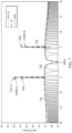
- FIG. 7 illustrates a portion of the frequency response of a two-antenna full IQ phased array receiver (waveform 702), the response of a two-antenna real phased array receiver (waveform 704), and the response of a two-antenna hybrid phased array receiver (waveform 706) to a wideband, baseband chirp interferer.
- the SIR is normalized to values for a single antenna, the direction of arrival of the target signal is 15 degrees, and the direction of arrival of the interferer is zero degrees.
- the real receiver signal spectrum is comb-like.
- a quadrature signal component would also have a comb-like spectrum but with peaks and nulls that are swapped as compared to the in-phase component (i.e., the quadrature signal component would have a frequency orthogonal ripple as compared to the in-phase signal component). Therefore, the full-IQ interferer (see waveform 702) has a flat spectrum that is the sum of the in-phase received digital signal spectrum (see waveform 704) and the quadrature received digital signal spectrum.
- the in-phase received digital signal spectrum and the quadrature received digital signal spectrum each have a comb-like spectrum that cause complex signal I + j Q to have the same spectral peak envelope (e.g., -74.8 dBV 2 /Hz) as the individual -phase received digital signal spectrum and quadrature received digital signal spectrum.
- the SIR of the two-antenna hybrid phased array receiver and two-antenna, full IQ phased array receiver at a beat signal frequency is approximately 50.4 dB and is attenuated by approximately 6 dB in the two-antenna, real phased array receiver.
- the two-antenna full IQ phased array receiver fully suppresses the sideband signal image at 5 MHz.
- the two-antenna real phased array receiver attenuates the image at 5 MHz by 6 dB and the two-antenna hybrid beamformer system further suppresses the image, e.g., by another 3 dB.
- the beamforming signal response of the two-antenna full IQ phased array receiver response (i.e., I 0 + j Q 0 + I 1 + j Q 1 ) and the two-antenna hybrid beamformer (i.e., I 0 + j Q 1 ) is approximately 6 dB higher than the response of the two-antenna real phased array receiver response (i.e., I 0 + I 1 ) .
- the peak envelope of the interferer is the same for those four configurations for an interferer at approximately zero degrees direction of arrival. Therefore, both the two-antenna full IQ phased array receiver and the two-antenna hybrid phased array receiver configurations benefit from a maximum of 6 dB SIR advantage.
- Figures 8 and 9 illustrate the SINR as a function of direction of arrival of the target signal ( Fig. 8 with an interferer at zero degrees and a sweep of the target signal over the direction of arrival) and the SINR as a function of direction of arrival of interferer ( Fig. 9 with the target signal fixed at zero degrees and a sweep of the interferer over the direction of arrival) for a two-antenna full IQ phased array receiver, a two-antenna real phased array receiver, a two-antenna hybrid phased array receiver, and a single antenna full IQ receiver channel using antenna elements with a half-power beamwidth of +/-35°. Assuming that thermal noise is constant, the SINR is defined by the power received from one or more antenna.
- Beamforming causes coherent combination that focuses energy around zero degrees of waveform 806, which corresponds to a two-antenna real phased array receiver and waveform 804, which corresponds to the two-antenna full IQ phased array receiver or the two-antenna hybrid phased array receiver, as compared to waveform 802, which corresponds to a single antenna full IQ receiver channel.
- phased array receiver configurations When sweeping the target signal direction of arrival, phased array receiver configurations have an array factor power loss as compared to the single antenna full IQ receiver configuration.
- the two-antenna hybrid phased array receiver configuration and the two-antenna full IQ phased array receiver configuration have 6 dB greater SIR than the two-antenna real phased array receiver configuration.
- the two-antenna full IQ phased array receiver configuration maintains the 6 dB SIR advantage over the two-antenna real phased array receiver configuration (waveform 904)
- the two-antenna hybrid phased array receiver configuration is a compromise between the two-antenna real phased array receiver configuration (waveform 904) and the single antenna full IQ phased array receiver configuration (waveform 906) for a direction of arrival of the interferer having an absolute value of the less than thirty degrees (i.e.,
- the two-antenna hybrid phased array receiver configuration has less performance improvement as compared to the two-antenna real phased array receiver configuration.
- ⁇ A ⁇ sin ⁇ ⁇ 2 d ⁇ .
- orthogonality between in-phase received digital signal I 0 and quadrature received digital signal Q 1 of the two-antenna hybrid phased array receiver is completely lost.
- a method for receiving a radio frequency signal using a phased array receiver includes generating a first digital received signal based on a first signal received from a first antenna and a local clock signal. The method includes generating a second digital received signal based on a second signal received from a second antenna and the local clock signal. The method includes combining the first digital received signal and the second digital received signal to generate a first complex received signal.
- the second antenna is spaced by a predetermined distance from the first antenna.
- the first antenna and the second antenna are configured for a small direction of arrival of a received signal.
- the method further includes delaying the first signal received from the first antenna to generate a delayed signal.
- the delayed signal is ninety degrees out of phase from the first signal received from the first antenna.
- the first digital received signal is generated using the delayed signal.
- the method further includes generating a first clock signal based on the local clock signal. In an embodiment, the method further includes generating a second clock signal based on the local clock signal. In an embodiment of the method, the second clock signal is ninety degrees out of phase from the first clock signal. In an embodiment of the method, generating the first digital received signal uses the first clock signal, and generating the second digital received signal uses the second clock signal.
- the method further includes generating a third digital received signal based on a third signal received from a third antenna and the local clock signal. In an embodiment, the method further includes generating a fourth digital received signal based on a fourth signal received from a fourth antenna and the local clock signal. In an embodiment, the method further includes combining the third digital received signal and the fourth digital received signal to generate a second complex received signal. In an embodiment, the third antenna is spaced by the predetermined distance from the second antenna, and the fourth antenna is spaced by the predetermined distance from the third antenna.
- the method further includes delaying the first signal received from the first antenna to generate a delayed signal.
- the delayed signal is ninety degrees out of phase from the first signal received from the first antenna.
- the method further includes delaying the fourth signal received from the fourth antenna to generate a second delayed signal.
- the second delayed signal is ninety degrees out of phase from the fourth signal received from the fourth antenna.
- the first digital received signal is generated using the delayed signal and the local clock signal
- the fourth digital received signal is generated using the second delayed signal and the local clock signal.
- the method further includes generating a first clock signal based on the local clock signal. In an embodiment, the method further includes generating a second clock signal based on the local clock signal. In an embodiment, the method further includes generating a third clock signal based on the local clock signal and generating a fourth clock signal based on the local clock signal. In an embodiment, the second clock signal and the third clock signal are ninety degrees out of phase from the first clock signal and the fourth clock signal.
- the first antenna, the second antenna, the third antenna, and the fourth antenna are configured for a small direction of arrival of a received signal.
- a phased array receiver includes a first receiver path configured to generate a first digital received signal based on a first signal received from a first antenna and a local clock signal.
- the phased array receiver includes a second receiver path configured to generate a second digital received signal based on a second signal received from a second antenna and the local clock signal.
- the phased array receiver includes a circuit configured to combine the first digital received signal and the second digital received signal to generate a first complex received signal.
- the second antenna is spaced by a predetermined distance from the first antenna.
- the phased array receiver further includes the first antenna, and the second antenna.
- the first antenna and the second antenna are configured for a small direction of arrival of a received signal.
- the first receiver path comprises a delay element coupled between the first antenna and the circuit.
- the phased array receiver further includes a second circuit configured to provide a first clock signal based on the local clock signal and configured to provide a second clock signal based on the local clock signal.
- the second clock signal is ninety degrees out of phase from the first clock signal.
- the first receiver path comprises a first mixer circuit responsive to the first clock signal and the second receiver path includes a second mixer circuit responsive to the second clock signal.
- the phased array receiver further includes a third receiver path configured to generate a third digital received signal based on a third signal received from a third antenna and the local clock signal. In an embodiment, the phased array receiver further includes a fourth receiver path configured to generate a fourth digital received signal based on a fourth signal received from a fourth antenna and the local clock signal. In an embodiment of the phased array receiver, the circuit is further configured to combine the third digital received signal and the fourth digital received signal to generate a second complex received signal. In an embodiment of the phased array receiver, the third antenna is spaced by the predetermined distance from the second antenna and the fourth antenna is spaced by the predetermined distance from the third antenna.
- the first receiver path includes a delay element coupled between the first antenna and the circuit.
- the fourth receiver path includes a second delay element coupled between the fourth antenna and the circuit.
- the phased array receiver further includes a second circuit configured to provide a first clock signal based on the local clock signal and configured to provide a second clock signal based on the local clock signal.
- the second clock signal is ninety degrees out of phase from the first clock signal.
- the phased array receiver further includes a third circuit configured to provide a third clock signal based on the local clock signal and configured to provide a fourth clock signal based on the local clock signal.
- the fourth clock signal is ninety degrees out of phase from the third clock signal.
- the first receiver path comprises a first mixer circuit responsive to the first clock signal
- the second receiver path comprises a second mixer circuit responsive to the second clock signal
- the third receiver path comprises a third mixer circuit responsive to the third clock signal
- the fourth receiver path comprises a fourth mixer circuit responsive to the fourth clock signal.
- the phased array receiver further includes the first antenna, the second antenna, the third antenna, and the fourth antenna.
- the first antenna and the second antenna are configured for a small direction of arrival of a received signal.
- a hybrid beamforming technique reduces the cost of a phased array receiver.
- the hybrid phased array receiver topology has improved performance as compared to a real phased array receiver for a small direction of arrival of an interferer and has the same performance as a full IQ phased array receiver for a zero degree direction of arrival of the interferer.
- the embodiments are described as including a carrier signal that has a predetermined frequency of 80 GHz and ⁇ / 4 is approximately 1 mm, in other embodiments, other predetermined frequencies and other delays are used.
- the embodiments are described as including an array of antennas spaced apart by ⁇ / 2, where ⁇ is the wavelength of the carrier signal, in other embodiments, the antennas are spaced apart by different ratios of the wavelength of a carrier signal.
- the embodiments are described in a radar application, techniques described above are applicable to other beamforming applications.
Landscapes
- Engineering & Computer Science (AREA)
- Radar, Positioning & Navigation (AREA)
- Remote Sensing (AREA)
- Computer Networks & Wireless Communication (AREA)
- Physics & Mathematics (AREA)
- General Physics & Mathematics (AREA)
- Variable-Direction Aerials And Aerial Arrays (AREA)
Abstract
A method for receiving a radio frequency signal using a phased array receiver includes generating a first digital received signal based on a first signal received from a first antenna and a local clock signal. The method includes generating a second digital received signal based on a second signal received from a second antenna and the local clock signal. The method includes combining the first digital received signal and the second digital received signal to generate a first complex received signal. The second antenna is spaced by a predetermined distance from the first antenna.
Description
- This disclosure relates to receivers for radar applications.
- In general, a phased array receiver includes multiple receiver circuits coupled to multiple antennas. Each receiver circuit provides information about the angle of arrival of signals with respect to the antenna elements. Typically, each individual receiver circuit is coupled to an antenna in a phased array of identical antennas and is implemented using a real receiver topology or a full IQ receiver topology. The real receiver topology is relatively low-cost but is associated with reduced performance as compared to the full IQ receiver topology due to the inability of a real receiver to distinguish between positive frequencies and negative frequencies. The full IQ receiver allows distinction between positive frequencies and negative frequencies, thus enabling more functionality and higher performance than a real receiver topology. However, the full IQ receiver topology is more costly than the real receiver topology because it includes additional circuitry (e.g., an additional mixer, additional filters, an additional analog-to-digital converter, a phase shifting circuit, etc.). Thus, a full IQ receiver consumes more area and more current than a real receiver. Accordingly, improved techniques for receiving wireless signals using a phased array receiver are desired.
- The present invention is illustrated by way of example and is not limited by the accompanying figures, in which like references indicate similar elements. Elements in the figures are illustrated for simplicity and clarity and have not necessarily been drawn to scale.
-
Figure 1 illustrates a functional block diagram of a conventional IQ phased array receiver having two antennas. -
Figure 2 illustrates a functional block diagram of a conventional real receiver having two antennas. -
Figure 3 illustrates a functional block diagram of a hybrid IQ phased array receiver consistent with at least one embodiment of the invention. -
Figure 4 illustrates a functional block diagram of an alternative embodiment of a hybrid IQ phased array receiver consistent with at least one embodiment of the invention. -
Figure 5 illustrates waveforms of amplitude as a function of direction of arrival for positive and negative frequencies of a signal received using the receiver ofFig. 1 . -
Figure 6 illustrates waveforms of amplitude as a function of direction of arrival for positive and negative frequencies of a signal received using a hybrid IQ phased array receiver consistent with at least one embodiment of the invention. -
Figure 7 illustrates waveforms of Signal-to-Interference-Ratio (SIR) as a function of frequency for a conventional IQ phased array receiver, a real receiver, and a hybrid IQ phased array receiver. -
Figure 8 illustrates waveforms of Signal-to-Interference-plus Noise-Ratio (SINR) as a function of direction of arrival at an antenna array of a target signal in the presence of an interferer fixed at zero degrees for a conventional IQ phased array receiver, a real phased array receiver, a hybrid IQ phased array receiver, and a full IQ single antenna receiver. -
Figure 9 illustrates waveforms of Signal-to-Interference-plus Noise-Ratio (SINR) as a function of direction of arrival at an antenna array of an interferer in the presence of a target signal fixed at zero degrees for a conventional IQ phased array receiver, a real phased array receiver, a hybrid IQ phased array receiver, and a full IQ single antenna receiver. - The use of the same reference symbols in different drawings indicates similar or identical items.
- A hybrid phased array receiver includes N real receiver channels coupled to N corresponding antennas. Each of the N real receiver channels of the hybrid phased array receiver has a phase offset from a corresponding other real receiver channel of the hybrid phased array receiver. By appropriate combination of received signals, positive frequencies can be distinguished from negative frequencies, providing similar advantages as a phased array of N full IQ receiver channels, but at a cost approximately the same as the cost of N real receiver channels, which is less than the cost of N full IQ receiver channels. A hybrid phased array receiver has a higher signal-to-interferer ratio against wideband interference as compared to a real phased array receiver at a lower cost than a full IQ phased array receiver that provides a complex received signal per full IQ receiver channel.
- Referring to
Fig. 1 , full IQphased array receiver 100 includes two full IQ receiver channels (i.e., N= 2) in a beamforming receiver.Antenna 106 andantenna 108 are coupled to fullIQ receiver channel 102 and fullIQ receiver channel 104, respectively. In general, beamforming antennas are spaced by a distance that provides useful constructive and destructive interference patterns (e.g., λ / 2) that reduces or minimizes mutual coupling of the antennas. Larger spacings can result in higher grating lobes (i.e., unwanted beams).Antenna 106 is spaced by λ / 2 from antenna 108 (where λ is the wavelength of the radio frequency carrier signal) consistent with conventional beamforming techniques that estimate a direction of arrival at an antenna array of one or more signals received by full IQphased array receiver 100. In an embodiment of full IQphased array receiver 100, fullIQ receiver channel 102 and fullIQ receiver channel 104 are included inintegrated circuit 101. Each full IQ receiver channel n (where 0 ≤ n ≤ N-1) includes a low noise amplifier that is coupled to a corresponding antenna, an IQ clock generator configured to generate quadrature clock signals, and quadrature receiver paths that provide in-phase received digital signal In and quadrature received digital signal Qn todigital signal processor 122. For example, fullIQ receiver channel 102 includesquadrature clock generator 118, which generates two clock signals that are 90 degrees out of phase with each other based on local oscillator signal LO.Quadrature clock generator 118 provides one of those clock signals (e.g., 0° clock signal) to mixer 110 for use in reducing the received signal frequency to an intermediate frequency or baseband frequency to generate in-phase received digital signal I0.Quadrature clock generator 118 provides the other clock signal (e.g., 90° clock signal) to mixer 112 for use in reducing the received signal frequency to an intermediate frequency or a baseband frequency to generate quadrature received digital signal Q0. Similarly, fullIQ receiver channel 104 includesquadrature clock generator 120, which generates two clock signals that are 90 degrees out of phase with each other based on local oscillator signal LO.Quadrature clock generator 120 provides one of those clock signals (e.g., 90° clock signal) to mixer 114 for use in generating quadrature received digital signal Q1 and the other clock signal (e.g., 0° clock signal) to mixer 116 for use in generating in-phase received digital signal I1 . - Full
IQ receiver channel 102 provides in-phase received digital signal I0 and quadrature received digital signal Q0 todigital signal processor 122 and fullIQ receiver channel 104 provides in-phase received digital signal I1 and quadrature received digital signal Q1 todigital signal processor 122.Digital signal processor 122 combines the in-phase and quadrature components of each receiver channel to generate complex received digital signals (e.g., I0 + jQ0 and I1 + jQ1 ) that may be further processed according to conventional beamforming techniques. The two full IQ receiver channels of full IQphased array receiver 100 consume substantial area of integratedcircuit 101 and consume a substantial amount of current in operation. - In an alternative phased array receiver topology of a beamforming receiver, rather than generate an in-phase received digital signal and a quadrature digital signal for each receiver channel and antenna, a phased array receiver topology includes N real receiver channels that generate only a real signal for each channel and antenna, i.e., only one phase of a local oscillator clock signal and one antenna are used per channel and antenna. Referring to
Fig. 2 , realphased array receiver 200 includes two antennas (i.e., N = 2) and two real receiver channels in a beamforming receiver.Antenna 206 andantenna 208 are coupled toreal receiver channel 202 andreal receiver channel 204, respectively.Antenna 206 is spaced by λ / 2 fromantenna 208, consistent with conventional beamforming techniques that estimate a direction of arrival at a phased array of antennas of signals received byreal receiver array 200. In an embodiment,real receiver channel 202 andreal receiver channel 204 are included inintegrated circuit 201. Each real receiver channel n includes a low noise amplifier coupled to a corresponding antenna and a corresponding receiver path that provides real received digital signal In todigital signal processor 222. - For example,
real receiver channel 202 andreal receiver channel 204 each include a low noise amplifier, a frequency mixer to convert the corresponding RF signal to an intermediate frequency signal using a local oscillator signal, intermediate frequency filtering and gain stages, and an analog-to-digital converter to provide an output digital real received signal I0 and output digital real received signal I1 , respectively.Digital signal processor 122 combines the real signals provided by each channel to generate a received digital signal (e.g., I0 + I1 ) according to conventional beamforming techniques. The real topology substantially reduces the integrated circuit area and substantially reduces the current consumed by the phased array receiver in operation as compared to the full IQ receiver topology. However, the signals generated by a real topology do not distinguish between positive and negative frequencies. As a result, the real topology reduces SIR of a phased array receiver system by approximately 6 dB, thus substantially degrading system performance. - A hybrid phased array receiver in a beamforming receiver system includes N real receiver channels coupled to N corresponding antennas. Each of the N real receiver channels has a phase offset from a corresponding other real receiver channel of the N receiver channels. Digital received signals generated by the N real receiver channels are combined to generate N / 2 complex received signals. The hybrid phased array receiver has reduced power consumption in operation and consumes less integrated circuit area than a full IQ phased array receiver topology described above and has improved performance as compared to a real phased array receiver topology described above. Each antenna of hybrid
phased array receiver 300 is coupled to a real receiver channel that includes a low noise amplifier, a frequency mixer to convert the RF signal to an intermediate frequency signal, intermediate frequency filtering and gain stages, and an analog-to-digital converter to provide an output digital signal i.e., in-phase received digital signal In or quadrature received digital signal Qn+1 , where n is an antenna index and 0 ≤ n ≤ N-1. Each hybrid receiver channel includes two antennas coupled to corresponding real receiver paths that generate in-phase received digital signal I n and a quadrature received digital signal Qn+1. The corresponding real receiver paths provide a phase shift of 90 degrees between in-phase received digital signal In and quadrature received digital signal Qn+1. - Referring to
Fig. 3 , hybridphased array receiver 300 includes two hybrid receiver channels formed from four real receiver channels coupled to four corresponding antennas (i.e., N = 4) in a beamforming receiver.Antenna 306 andantenna 308 are coupled tohybrid receiver channel 302.Antenna 310 andantenna 312 are coupled tohybrid receiver channel 304.Antenna 306 is spaced by λ / 2 fromantenna 308, which is spaced by λ / 2 fromantenna 310.Antenna 310 is spaced by λ / 2 fromantenna 312. In an embodiment,hybrid receiver channel 302 andhybrid receiver channel 304 are included in integratedcircuit 301. - In an embodiment,
hybrid receiver channel 302 includesquadrature clock generator 326, which generates two clock signals that are 90 degrees out of phase with each other based on local oscillator signal LO.Quadrature clock generator 326 provides one of those clock signals (e.g., 0° clock signal) tomixer 318 for use in generating in-phase received signal I0 and the other clock signal (e.g., 90° clock signal) tomixer 320 for use in generating quadrature received digital signal Q1. Similarly,hybrid receiver channel 304 includesquadrature clock generator 328, which generates two clock signals that are 90 degrees out of phase with each other based on local oscillator signal LO.Quadrature clock generator 328 provides one of those clock signals (e.g., 90° clock signal) tomixer 322 for use in generating quadrature received digital signal Q3 and the other clock signal (e.g., 0° clock signal) tomixer 324 for use in generating in-phase received digital signal I3 . -
Hybrid receiver channel 302 provides in-phase received digital signal I0, which corresponds to the real receiver channel coupled toantenna 306, and quadrature received digital signal Q1, which corresponds to the real receiver channel coupled toantenna 308, todigital signal processor 330.Hybrid receiver channel 304 provides quadrature received digital signal Q2, which corresponds to the real receiver channel coupled toantenna 310, and in-phase received digital signal I3 , which corresponds to the real receiver channel coupled toantenna 312, todigital signal processor 330.Digital signal processor 330 combines the in-phase received digital signal and quadrature received digital signal provided by each hybrid channel to generate complex received signals (e.g., I0 + jQ1 and I3 + jQ2 ) that may be further processed according to conventional beamforming techniques. Although two hybrid receiver channels including four real receiver channels and four corresponding antennas are illustrated, other numbers of N / 2 hybrid receiver channels corresponding to N real receiver channels and N antennas may be used to generate N / 2 received complex digital signals. - In another embodiment of a hybrid phased array receiver, rather than use a quadrature clock generator to generate a phase shift for alternate receiver paths, a phase shift is generated by delaying the received signal between an antenna and a mixer of one real receiver path in a pair of real receiver paths. In at least one embodiment, the delay is implemented using an integrated circuit delay element (e.g., a conductive trace having a length of λ / 4 for antennas spaced apart by λ / 2). In at least one embodiment, the delay is implemented using a delay element formed on the printed circuit board (e.g., a conductive trace having a length of λ / 4 for antennas spaced apart by λ / 2). In at least one embodiment, the delay is implemented in the antenna (e.g., increased length by λ / 4 of an antenna in a pair of antennas coupled to a hybrid receiver path).
- Referring to
Fig. 4 , hybridphase array receiver 400 includes four (i.e., N = 4) real receiver channels coupled to four corresponding antennas and configured as two (i.e., N / 2 = 2) hybrid receiver channels in a beamforming receiver.Antenna 406 andantenna 408 are coupled to corresponding real receiver channels ofhybrid receiver channel 402.Antenna 410 andantenna 412 are coupled to corresponding real receiver channels ofhybrid receiver channel 404.Antenna 406 is spaced by λ / 2 fromantenna 408, which is spaced by λ / 2 fromantenna 410.Antenna 410 is spaced by λ / 2 fromantenna 412. In an embodiment,hybrid receiver channel 402 andhybrid receiver channel 404 are included inintegrated circuit 401. Each antenna is coupled to a real receiver channel that includes a low noise amplifier, a frequency mixer to convert the RF signal to an intermediate frequency signal, intermediate frequency filtering and gain stages, and an analog-to-digital converter to provide in-phase received digital signal I n or quadrature received digital signal Q n+1 , where n is the antenna index and 0 ≤ n ≤ N-1. - Each hybrid receiver channel includes two antennas coupled to corresponding real receiver paths that generate an in-phase received signal or a quadrature received signal. The receiver path coupled to
antenna 406 and the receiver path coupled toantenna 412 includedelay element 414 anddelay element 416, respectively.Hybrid receiver channel 402 provides in-phase received digital signal I0 and quadrature received digital signal Q1 todigital signal processor 426 andhybrid receiver channel 404 provides in-phase received digital signal I3 and quadrature received digital signal Q2 todigital signal processor 426.Digital signal processor 426 combines the in-phase and quadrature received digital signals generated by each hybrid receiver channel to generate a corresponding complex received signal (e.g., I0 + jQ1 and I3 +jQ2 ) that may be further processed according to conventional beamforming techniques. - In at least one embodiment of a beamforming communications system, an RF carrier signal has a predetermined frequency of 80 GHz and λ / 4 is approximately 1 mm for antennas spaced apart by λ / 2. In general, implementing the delay using a conductive trace on a printed circuit board is less expensive than implementing the delay on the integrated circuit. A conventional printed circuit board physical design includes centimeters of conductive traces coupled to corresponding antennas. Therefore, including an additional millimeter of conductive material on the printed circuit board to implement a phase delay for the hybrid phased array receiver topology does not substantially affect the cost of the printed circuit board. In contrast, integrated circuit die are typically measured in millimeters, thus an additional millimeter of conductive material consumes a substantial area of the integrated circuit die.
- Referring to
Figs. 1 and5 , in an embodiment of full IQ phasedarray receiver 100 that includes two antennas spaced apart by λ / 2, the gain (AMP) is the sum of the amplitude of the signal received by the first antenna (i.e., A1) and the amplitude of the signal received by the second antenna (i.e., A2):

array receiver 100 is as follows:
- Referring to
Figs. 3 and6 , an embodiment of a hybrid phased array receiver that includes two antennas spaced apart by λ / 2 (e.g., hybrid receiver channel 302) has a gain as follows:


- In a typical radar application (e.g., frequency modulated continuous wave radar), interferers tend to appear as wideband, baseband chirps. Such interferers contribute to the noise floor of the received signal.
Figure 7 illustrates a portion of the frequency response of a two-antenna full IQ phased array receiver (waveform 702), the response of a two-antenna real phased array receiver (waveform 704), and the response of a two-antenna hybrid phased array receiver (waveform 706) to a wideband, baseband chirp interferer. The SIR is normalized to values for a single antenna, the direction of arrival of the target signal is 15 degrees, and the direction of arrival of the interferer is zero degrees. The real receiver signal spectrum is comb-like. A quadrature signal component would also have a comb-like spectrum but with peaks and nulls that are swapped as compared to the in-phase component (i.e., the quadrature signal component would have a frequency orthogonal ripple as compared to the in-phase signal component). Therefore, the full-IQ interferer (see waveform 702) has a flat spectrum that is the sum of the in-phase received digital signal spectrum (see waveform 704) and the quadrature received digital signal spectrum. The in-phase received digital signal spectrum and the quadrature received digital signal spectrum each have a comb-like spectrum that cause complex signal I + jQ to have the same spectral peak envelope (e.g., -74.8 dBV2/Hz) as the individual -phase received digital signal spectrum and quadrature received digital signal spectrum. - The SIR of the two-antenna hybrid phased array receiver and two-antenna, full IQ phased array receiver at a beat signal frequency (e.g., -5 MHz) is approximately 50.4 dB and is attenuated by approximately 6 dB in the two-antenna, real phased array receiver. The two-antenna full IQ phased array receiver fully suppresses the sideband signal image at 5 MHz. The two-antenna real phased array receiver attenuates the image at 5 MHz by 6 dB and the two-antenna hybrid beamformer system further suppresses the image, e.g., by another 3 dB. The beamforming signal response of the two-antenna full IQ phased array receiver response (i.e., I0 + jQ0 + I1 + jQ1 ) and the two-antenna hybrid beamformer (i.e., I0 + jQ1 ) is approximately 6 dB higher than the response of the two-antenna real phased array receiver response (i.e., I0 + I1 ). In addition, the peak envelope of the interferer is the same for those four configurations for an interferer at approximately zero degrees direction of arrival. Therefore, both the two-antenna full IQ phased array receiver and the two-antenna hybrid phased array receiver configurations benefit from a maximum of 6 dB SIR advantage.
-
Figures 8 and9 illustrate the SINR as a function of direction of arrival of the target signal (Fig. 8 with an interferer at zero degrees and a sweep of the target signal over the direction of arrival) and the SINR as a function of direction of arrival of interferer (Fig. 9 with the target signal fixed at zero degrees and a sweep of the interferer over the direction of arrival) for a two-antenna full IQ phased array receiver, a two-antenna real phased array receiver, a two-antenna hybrid phased array receiver, and a single antenna full IQ receiver channel using antenna elements with a half-power beamwidth of +/-35°. Assuming that thermal noise is constant, the SINR is defined by the power received from one or more antenna. Beamforming causes coherent combination that focuses energy around zero degrees ofwaveform 806, which corresponds to a two-antenna real phased array receiver andwaveform 804, which corresponds to the two-antenna full IQ phased array receiver or the two-antenna hybrid phased array receiver, as compared towaveform 802, which corresponds to a single antenna full IQ receiver channel. - When sweeping the target signal direction of arrival, phased array receiver configurations have an array factor power loss as compared to the single antenna full IQ receiver configuration. The two-antenna hybrid phased array receiver configuration and the two-antenna full IQ phased array receiver configuration have 6 dB greater SIR than the two-antenna real phased array receiver configuration. When sweeping the interferer direction of arrival, the two-antenna full IQ phased array receiver configuration (waveform 902) maintains the 6 dB SIR advantage over the two-antenna real phased array receiver configuration (waveform 904), whereas the two-antenna hybrid phased array receiver configuration (waveform 908) is a compromise between the two-antenna real phased array receiver configuration (waveform 904) and the single antenna full IQ phased array receiver configuration (waveform 906) for a direction of arrival of the interferer having an absolute value of the less than thirty degrees (i.e., |DOA| < 30°). Beyond thirty degrees of the absolute value of the direction of arrival of the interferer (i.e., |DOA| > 30°), the two-antenna hybrid phased array receiver configuration has less performance improvement as compared to the two-antenna real phased array receiver configuration. The relationship described with reference to
Figs. 7 ,8 , and9 are specific for antennas spaced apart by λ/2, where interelement phase delay
- In an embodiment, a method for receiving a radio frequency signal using a phased array receiver includes generating a first digital received signal based on a first signal received from a first antenna and a local clock signal. The method includes generating a second digital received signal based on a second signal received from a second antenna and the local clock signal. The method includes combining the first digital received signal and the second digital received signal to generate a first complex received signal. The second antenna is spaced by a predetermined distance from the first antenna.
- In an embodiment of the method, the first antenna and the second antenna are configured for a small direction of arrival of a received signal.
- In an embodiment of the method, the predetermined distance is λ / 2, where λ = c/f, c is the speed of light, f is a predetermined frequency of a carrier signal.
- In an embodiment, the method further includes delaying the first signal received from the first antenna to generate a delayed signal. The delayed signal is ninety degrees out of phase from the first signal received from the first antenna. The first digital received signal is generated using the delayed signal.
- In an embodiment, the method further includes generating a first clock signal based on the local clock signal. In an embodiment, the method further includes generating a second clock signal based on the local clock signal. In an embodiment of the method, the second clock signal is ninety degrees out of phase from the first clock signal. In an embodiment of the method, generating the first digital received signal uses the first clock signal, and generating the second digital received signal uses the second clock signal.
- In an embodiment, the method further includes generating a third digital received signal based on a third signal received from a third antenna and the local clock signal. In an embodiment, the method further includes generating a fourth digital received signal based on a fourth signal received from a fourth antenna and the local clock signal. In an embodiment, the method further includes combining the third digital received signal and the fourth digital received signal to generate a second complex received signal. In an embodiment, the third antenna is spaced by the predetermined distance from the second antenna, and the fourth antenna is spaced by the predetermined distance from the third antenna.
- In an embodiment, the method further includes delaying the first signal received from the first antenna to generate a delayed signal. The delayed signal is ninety degrees out of phase from the first signal received from the first antenna. In an embodiment, the method further includes delaying the fourth signal received from the fourth antenna to generate a second delayed signal. The second delayed signal is ninety degrees out of phase from the fourth signal received from the fourth antenna. In an embodiment, the first digital received signal is generated using the delayed signal and the local clock signal, and the fourth digital received signal is generated using the second delayed signal and the local clock signal.
- In an embodiment, the method further includes generating a first clock signal based on the local clock signal. In an embodiment, the method further includes generating a second clock signal based on the local clock signal. In an embodiment, the method further includes generating a third clock signal based on the local clock signal and generating a fourth clock signal based on the local clock signal. In an embodiment, the second clock signal and the third clock signal are ninety degrees out of phase from the first clock signal and the fourth clock signal.
- In an embodiment of the method, the first antenna, the second antenna, the third antenna, and the fourth antenna are configured for a small direction of arrival of a received signal. In an embodiment, the predetermined distance is λ / 2, where λ = c / f, c is the speed of light, f is a predetermined frequency of a carrier signal.
- In an embodiment, a phased array receiver includes a first receiver path configured to generate a first digital received signal based on a first signal received from a first antenna and a local clock signal. The phased array receiver includes a second receiver path configured to generate a second digital received signal based on a second signal received from a second antenna and the local clock signal. The phased array receiver includes a circuit configured to combine the first digital received signal and the second digital received signal to generate a first complex received signal. The second antenna is spaced by a predetermined distance from the first antenna.
- In an embodiment, the phased array receiver further includes the first antenna, and the second antenna. In an embodiment of the phased array receiver, the first antenna and the second antenna are configured for a small direction of arrival of a received signal.
- In an embodiment of the phased array receiver, the predetermined distance is λ / 2, where λ = c / f, c is the speed of light, f is a predetermined frequency of a carrier signal.
- In an embodiment of the phased array receiver, the first receiver path comprises a delay element coupled between the first antenna and the circuit.
- In an embodiment of the phased array receiver, the predetermined distance is λ / 2, where λ = c / f, c is the speed of light, f is a predetermined frequency of a carrier signal, and the delay element is a conductive trace on a printed circuit board having a length of λ / 4.
- In an embodiment, the phased array receiver further includes a second circuit configured to provide a first clock signal based on the local clock signal and configured to provide a second clock signal based on the local clock signal. The second clock signal is ninety degrees out of phase from the first clock signal. In an embodiment of the phased array receiver, the first receiver path comprises a first mixer circuit responsive to the first clock signal and the second receiver path includes a second mixer circuit responsive to the second clock signal.
- In an embodiment, the phased array receiver further includes a third receiver path configured to generate a third digital received signal based on a third signal received from a third antenna and the local clock signal. In an embodiment, the phased array receiver further includes a fourth receiver path configured to generate a fourth digital received signal based on a fourth signal received from a fourth antenna and the local clock signal. In an embodiment of the phased array receiver, the circuit is further configured to combine the third digital received signal and the fourth digital received signal to generate a second complex received signal. In an embodiment of the phased array receiver, the third antenna is spaced by the predetermined distance from the second antenna and the fourth antenna is spaced by the predetermined distance from the third antenna.
- In an embodiment of the phased array receiver, the first receiver path includes a delay element coupled between the first antenna and the circuit. In an embodiment of the phased array receiver, the fourth receiver path includes a second delay element coupled between the fourth antenna and the circuit.
- In an embodiment, the phased array receiver further includes a second circuit configured to provide a first clock signal based on the local clock signal and configured to provide a second clock signal based on the local clock signal. The second clock signal is ninety degrees out of phase from the first clock signal. In an embodiment, the phased array receiver further includes a third circuit configured to provide a third clock signal based on the local clock signal and configured to provide a fourth clock signal based on the local clock signal. The fourth clock signal is ninety degrees out of phase from the third clock signal. In an embodiment of the phased array receiver, the first receiver path comprises a first mixer circuit responsive to the first clock signal, the second receiver path comprises a second mixer circuit responsive to the second clock signal, the third receiver path comprises a third mixer circuit responsive to the third clock signal, and the fourth receiver path comprises a fourth mixer circuit responsive to the fourth clock signal.
- In an embodiment, the phased array receiver further includes the first antenna, the second antenna, the third antenna, and the fourth antenna. In an embodiment of the phased array receiver, the first antenna and the second antenna are configured for a small direction of arrival of a received signal. In an embodiment of the phased array receiver, the predetermined distance is λ / 2, where λ = c If, c is the speed of light, and f is a predetermined frequency of a carrier signal.
- Thus, a hybrid beamforming technique reduces the cost of a phased array receiver. The hybrid phased array receiver topology has improved performance as compared to a real phased array receiver for a small direction of arrival of an interferer and has the same performance as a full IQ phased array receiver for a zero degree direction of arrival of the interferer.
- Although the invention is described herein with reference to specific embodiments, various modifications and changes can be made without departing from the scope of the present invention as set forth in the claims below. For example, although the embodiments are described as including a carrier signal that has a predetermined frequency of 80 GHz and λ / 4 is approximately 1 mm, in other embodiments, other predetermined frequencies and other delays are used. In addition, although the embodiments are described as including an array of antennas spaced apart by λ / 2, where λ is the wavelength of the carrier signal, in other embodiments, the antennas are spaced apart by different ratios of the wavelength of a carrier signal. Further, although the embodiments are described in a radar application, techniques described above are applicable to other beamforming applications. Accordingly, the specification and figures are to be regarded in an illustrative rather than a restrictive sense, and all such modifications are intended to be included within the scope of the present invention. Any benefits, advantages, or solutions to problems that are described herein with regard to specific embodiments are not intended to be construed as a critical, required, or essential feature or element of any or all the claims.
- Unless stated otherwise, terms such as "first" and "second" are used to arbitrarily distinguish between the elements such terms describe. Thus, these terms are not necessarily intended to indicate temporal or other prioritization of such elements.
Claims (15)
- A phased array receiver comprising:a first receiver path configured to generate a first digital received signal based on a first signal received from a first antenna and a local clock signal;a second receiver path configured to generate a second digital received signal based on a second signal received from a second antenna and the local clock signal; anda circuit configured to combine the first digital received signal and the second digital received signal to generate a first complex received signal,wherein the second antenna is spaced by a predetermined distance from the first antenna.
- The phased array receiver as recited in claim 1, further comprising:the first antenna; andthe second antenna,wherein the first antenna and the second antenna are configured for a small direction of arrival of a received signal.
- The phased array receiver as recited in claim 2,
wherein the predetermined distance is λ / 2, where λ = c / f, c is the speed of light, and f is a predetermined frequency of a carrier signal. - The phased array receiver as recited in any preceding claim, wherein the first receiver path comprises a delay element coupled between the first antenna and the circuit.
- The phased array receiver as recited in claim 4,wherein the predetermined distance is λ / 2, where λ = c / f, c is the speed of light, and f is a predetermined frequency of a carrier signal, andwherein the delay element is a conductive trace on a printed circuit board having a length of λ / 4.
- The phased array receiver as recited in any preceding claim, further comprising:a second circuit configured to provide a first clock signal based on the local clock signal and configured to provide a second clock signal based on the local clock signal, the second clock signal being ninety degrees out of phase from the first clock signal,wherein the first receiver path comprises a first mixer circuit responsive to the first clock signal, andwherein the second receiver path comprises a second mixer circuit responsive to the second clock signal.
- The phased array receiver as recited in any preceding claim, further comprising:a third receiver path configured to generate a third digital received signal based on a third signal received from a third antenna and the local clock signal; anda fourth receiver path configured to generate a fourth digital received signal based on a fourth signal received from a fourth antenna and the local clock signal,wherein the circuit is further configured to combine the third digital received signal and the fourth digital received signal to generate a second complex received signal,wherein the third antenna is spaced by the predetermined distance from the second antenna and the fourth antenna is spaced by the predetermined distance from the third antenna.
- The phased array receiver as recited in claim 7,wherein the first receiver path comprises a delay element coupled between the first antenna and the circuit, andwherein the fourth receiver path comprises a second delay element coupled between the fourth antenna and the circuit.
- The phased array receiver as recited in claim 7 or 8, further comprising:a second circuit configured to provide a first clock signal based on the local clock signal and configured to provide a second clock signal based on the local clock signal, the second clock signal being ninety degrees out of phase from the first clock signal; anda third circuit configured to provide a third clock signal based on the local clock signal and configured to provide a fourth clock signal based on the local clock signal, the fourth clock signal being ninety degrees out of phase from the third clock signal,wherein the first receiver path comprises a first mixer circuit responsive to the first clock signal,wherein the second receiver path comprises a second mixer circuit responsive to the second clock signal,wherein the third receiver path comprises a third mixer circuit responsive to the third clock signal, andwherein the fourth receiver path comprises a fourth mixer circuit responsive to the fourth clock signal.
- The phased array receiver as recited in any of claims 7 to 9, further comprising:the first antenna;the second antenna,the third antenna; andthe fourth antenna,wherein the first antenna and the second antenna are configured for a small direction of arrival of a received signal, andwherein the predetermined distance is λ / 2, where λ = c / f, c is the speed of light, and f is a predetermined frequency of a carrier signal.
- A method for receiving a radio frequency signal using a phased array receiver, the method comprising:generating a first digital received signal based on a first signal received from a first antenna and a local clock signal;generating a second digital received signal based on a second signal received from a second antenna and the local clock signal; andcombining the first digital received signal and the second digital received signal to generate a first complex received signal,wherein the second antenna is spaced by a predetermined distance from the first antenna.
- The method as recited in claim 11, wherein the first antenna and the second antenna are configured for a small direction of arrival of a received signal.
- The method as recited in claim 11 or 12,
wherein the predetermined distance is λ / 2, where λ = c / f, c is the speed of light, and f is a predetermined frequency of a carrier signal. - The method as recited in any of claims 11 to 13, further comprising:delaying the first signal received from the first antenna to generate a delayed signal, the delayed signal being ninety degrees out of phase from the first signal received from the first antenna,wherein the first digital received signal is generated using the delayed signal.
- The method as recited in any of claims 11 to 14, further comprising:generating a first clock signal based on the local clock signal,generating a second clock signal based on the local clock signal, the second clock signal being ninety degrees out of phase from the first clock signal,wherein generating the first digital received signal uses the first clock signal, andwherein generating the second digital received signal uses the second clock signal.
Applications Claiming Priority (1)
| Application Number | Priority Date | Filing Date | Title |
|---|---|---|---|
| US18/524,517 US20250180695A1 (en) | 2023-11-30 | 2023-11-30 | Hybrid quadrature receive array |
Publications (1)
| Publication Number | Publication Date |
|---|---|
| EP4564043A1 true EP4564043A1 (en) | 2025-06-04 |
Family
ID=93741183
Family Applications (1)
| Application Number | Title | Priority Date | Filing Date |
|---|---|---|---|
| EP24216217.0A Pending EP4564043A1 (en) | 2023-11-30 | 2024-11-28 | Hybrid quadrature receive array |
Country Status (3)
| Country | Link |
|---|---|
| US (1) | US20250180695A1 (en) |
| EP (1) | EP4564043A1 (en) |
| CN (1) | CN120065130A (en) |
Citations (2)
| Publication number | Priority date | Publication date | Assignee | Title |
|---|---|---|---|---|
| US20200363520A1 (en) * | 2018-01-18 | 2020-11-19 | Robert Bosch Gmbh | Fmcw radar sensor |
| US20230184889A1 (en) * | 2021-12-14 | 2023-06-15 | Infineon Technologies Ag | Receiver down-converter architecture including an hybrid coupler, a quadrature down-converter and a baseband signal linear combiner |
Family Cites Families (7)
| Publication number | Priority date | Publication date | Assignee | Title |
|---|---|---|---|---|
| US7076227B1 (en) * | 1998-12-03 | 2006-07-11 | Apex/Eclipse Systems, Inc. | Receiving system with improved directivity and signal to noise ratio |
| US9041602B2 (en) * | 2011-11-14 | 2015-05-26 | Earl W. McCune, Jr. | Phased array transmission methods and apparatus |
| DE102012009402B3 (en) * | 2012-05-10 | 2013-07-04 | Eads Deutschland Gmbh | Phased array antenna and method for processing received signals in a phased array antenna |
| CN102857280B (en) * | 2012-07-24 | 2014-12-31 | 电子科技大学 | Four-dimensional antenna array based secret communication system and method thereof |
| US20230129253A1 (en) * | 2018-11-02 | 2023-04-27 | Innophase, Inc. | Reconfigurable phase array |
| CN113395232B (en) * | 2021-08-16 | 2021-11-05 | 深圳捷扬微电子有限公司 | Pulse ultra-wideband multi-antenna delay receiver and method for acquiring incident angle |
| DE102024100870A1 (en) * | 2024-01-12 | 2025-07-17 | Friedrich-Alexander-Universität Erlangen-Nürnberg, Körperschaft des öffentlichen Rechts | Procedure and recipient |
-
2023
- 2023-11-30 US US18/524,517 patent/US20250180695A1/en active Pending
-
2024
- 2024-11-28 EP EP24216217.0A patent/EP4564043A1/en active Pending
- 2024-11-29 CN CN202411736896.XA patent/CN120065130A/en active Pending
Patent Citations (2)
| Publication number | Priority date | Publication date | Assignee | Title |
|---|---|---|---|---|
| US20200363520A1 (en) * | 2018-01-18 | 2020-11-19 | Robert Bosch Gmbh | Fmcw radar sensor |
| US20230184889A1 (en) * | 2021-12-14 | 2023-06-15 | Infineon Technologies Ag | Receiver down-converter architecture including an hybrid coupler, a quadrature down-converter and a baseband signal linear combiner |
Non-Patent Citations (1)
| Title |
|---|
| SALMON NEIL A ET AL: "Minimising the costs of next generation aperture synthesis passive millimetre wave imagers", MILLIMETRE WAVE AND TERAHERTZ SENSORS AND TECHNOLOGY IV, SPIE, 1000 20TH ST. BELLINGHAM WA 98225-6705 USA, vol. 8188, no. 1, 6 October 2011 (2011-10-06), pages 1 - 6, XP060020492, DOI: 10.1117/12.899309 * |
Also Published As
| Publication number | Publication date |
|---|---|
| CN120065130A (en) | 2025-05-30 |
| US20250180695A1 (en) | 2025-06-05 |
Similar Documents
| Publication | Publication Date | Title |
|---|---|---|
| US7683833B2 (en) | Phase shifting and combining architecture for phased arrays | |
| CN1820429B (en) | Millimeter wave band wireless communication method and system | |
| US20210266052A1 (en) | Flexible beamforming using frequency-division multiplexing | |
| US20120086602A1 (en) | Hybrid beam forming apparatus in wideband wireless communication system | |
| Leong et al. | A full duplex capable retrodirective array system for high-speed beam tracking and pointing applications | |
| US20060262013A1 (en) | Full-duplex dual-frequency self-steering array using phase detection & phase shifting | |
| Statnikov et al. | A lens-coupled 210–270 GHz circularly polarized FMCW radar transceiver module in SiGe technology | |
| Ko et al. | 24-GHz 4TX–4RX phased array transceiver with automatic beam steering mode for FMCW radar applications | |
| US10630322B2 (en) | High power signal communications within a power limit | |
| CN102725651A (en) | Detector system | |
| JP2018032892A (en) | Wireless communication device, and phase adjustment method | |
| Sakhnini et al. | A codebook approach to spillover cancellation in multi-antenna radar and communication systems | |
| Fusco et al. | High-performance IQ modulator-based phase conjugator for modular retrodirective antenna array implementation | |
| US20250180695A1 (en) | Hybrid quadrature receive array | |
| Liu et al. | Progress in HFSWR research at Harbin Institute of Technology | |
| O'Donoughue | Analysis of dual-transmit beams | |
| Umehira et al. | Experimental Evaluation of Interference Suppression using Interference Replica to Improve Spectrum Efficiency for Automotive CS Radars | |
| Wang et al. | Impact of phase noise on sidelobe cancellation system utilizing distributed phase-lock-loops | |
| Chen et al. | A 140GHz FMCW Radar with 22dB Wideband RF-Domain Multipath Self-Interference Cancellation in 28nm CMOS | |
| Entesari et al. | Integrated Phased-Array Frequency-Modulated Continuous-Wave Radar Transceivers on Silicon | |
| Adams | Beam tagging for control of adaptive transmitting arrays | |
| O'Hagan et al. | Signal and interference analysis: Proposed analogue signal suppression techniques for PCL radar | |
| Ardakani et al. | Time Division Duplex Beam Switching System Using a Common Multi-Port Junction Transceiver | |
| Fazzini et al. | Simplified Frequency-Diverse Array Architecture for Surveillance Purposes | |
| Suban et al. | OFDM based Waveform Design and Digital Beamforming Technique for RADCOM System |
Legal Events
| Date | Code | Title | Description |
|---|---|---|---|
| PUAI | Public reference made under article 153(3) epc to a published international application that has entered the european phase |
Free format text: ORIGINAL CODE: 0009012 |
|
| STAA | Information on the status of an ep patent application or granted ep patent |
Free format text: STATUS: THE APPLICATION HAS BEEN PUBLISHED |
|
| AK | Designated contracting states |
Kind code of ref document: A1 Designated state(s): AL AT BE BG CH CY CZ DE DK EE ES FI FR GB GR HR HU IE IS IT LI LT LU LV MC ME MK MT NL NO PL PT RO RS SE SI SK SM TR |
|
| STAA | Information on the status of an ep patent application or granted ep patent |
Free format text: STATUS: REQUEST FOR EXAMINATION WAS MADE |
|
| 17P | Request for examination filed |
Effective date: 20251204 |