EP4563926A1 - Heat exchanger - Google Patents
Heat exchanger Download PDFInfo
- Publication number
- EP4563926A1 EP4563926A1 EP24215900.2A EP24215900A EP4563926A1 EP 4563926 A1 EP4563926 A1 EP 4563926A1 EP 24215900 A EP24215900 A EP 24215900A EP 4563926 A1 EP4563926 A1 EP 4563926A1
- Authority
- EP
- European Patent Office
- Prior art keywords
- inclined surface
- mountain portion
- mountain
- fin
- refrigerant
- Prior art date
- Legal status (The legal status is an assumption and is not a legal conclusion. Google has not performed a legal analysis and makes no representation as to the accuracy of the status listed.)
- Pending
Links
Images



Classifications
-
- F—MECHANICAL ENGINEERING; LIGHTING; HEATING; WEAPONS; BLASTING
- F28—HEAT EXCHANGE IN GENERAL
- F28D—HEAT-EXCHANGE APPARATUS, NOT PROVIDED FOR IN ANOTHER SUBCLASS, IN WHICH THE HEAT-EXCHANGE MEDIA DO NOT COME INTO DIRECT CONTACT
- F28D1/00—Heat-exchange apparatus having stationary conduit assemblies for one heat-exchange medium only, the media being in contact with different sides of the conduit wall, in which the other heat-exchange medium is a large body of fluid, e.g. domestic or motor car radiators
- F28D1/02—Heat-exchange apparatus having stationary conduit assemblies for one heat-exchange medium only, the media being in contact with different sides of the conduit wall, in which the other heat-exchange medium is a large body of fluid, e.g. domestic or motor car radiators with heat-exchange conduits immersed in the body of fluid
- F28D1/04—Heat-exchange apparatus having stationary conduit assemblies for one heat-exchange medium only, the media being in contact with different sides of the conduit wall, in which the other heat-exchange medium is a large body of fluid, e.g. domestic or motor car radiators with heat-exchange conduits immersed in the body of fluid with tubular conduits
- F28D1/053—Heat-exchange apparatus having stationary conduit assemblies for one heat-exchange medium only, the media being in contact with different sides of the conduit wall, in which the other heat-exchange medium is a large body of fluid, e.g. domestic or motor car radiators with heat-exchange conduits immersed in the body of fluid with tubular conduits the conduits being straight
- F28D1/0535—Heat-exchange apparatus having stationary conduit assemblies for one heat-exchange medium only, the media being in contact with different sides of the conduit wall, in which the other heat-exchange medium is a large body of fluid, e.g. domestic or motor car radiators with heat-exchange conduits immersed in the body of fluid with tubular conduits the conduits being straight the conduits having a non-circular cross-section
- F28D1/05366—Assemblies of conduits connected to common headers, e.g. core type radiators
- F28D1/05383—Assemblies of conduits connected to common headers, e.g. core type radiators with multiple rows of conduits or with multi-channel conduits
-
- F—MECHANICAL ENGINEERING; LIGHTING; HEATING; WEAPONS; BLASTING
- F28—HEAT EXCHANGE IN GENERAL
- F28F—DETAILS OF HEAT-EXCHANGE AND HEAT-TRANSFER APPARATUS, OF GENERAL APPLICATION
- F28F1/00—Tubular elements; Assemblies of tubular elements
- F28F1/10—Tubular elements and assemblies thereof with means for increasing heat-transfer area, e.g. with fins, with projections, with recesses
- F28F1/12—Tubular elements and assemblies thereof with means for increasing heat-transfer area, e.g. with fins, with projections, with recesses the means being only outside the tubular element
- F28F1/24—Tubular elements and assemblies thereof with means for increasing heat-transfer area, e.g. with fins, with projections, with recesses the means being only outside the tubular element and extending transversely
- F28F1/32—Tubular elements and assemblies thereof with means for increasing heat-transfer area, e.g. with fins, with projections, with recesses the means being only outside the tubular element and extending transversely the means having portions engaging further tubular elements
-
- F—MECHANICAL ENGINEERING; LIGHTING; HEATING; WEAPONS; BLASTING
- F28—HEAT EXCHANGE IN GENERAL
- F28F—DETAILS OF HEAT-EXCHANGE AND HEAT-TRANSFER APPARATUS, OF GENERAL APPLICATION
- F28F1/00—Tubular elements; Assemblies of tubular elements
- F28F1/10—Tubular elements and assemblies thereof with means for increasing heat-transfer area, e.g. with fins, with projections, with recesses
- F28F1/12—Tubular elements and assemblies thereof with means for increasing heat-transfer area, e.g. with fins, with projections, with recesses the means being only outside the tubular element
- F28F1/126—Tubular elements and assemblies thereof with means for increasing heat-transfer area, e.g. with fins, with projections, with recesses the means being only outside the tubular element consisting of zig-zag shaped fins
-
- F—MECHANICAL ENGINEERING; LIGHTING; HEATING; WEAPONS; BLASTING
- F28—HEAT EXCHANGE IN GENERAL
- F28D—HEAT-EXCHANGE APPARATUS, NOT PROVIDED FOR IN ANOTHER SUBCLASS, IN WHICH THE HEAT-EXCHANGE MEDIA DO NOT COME INTO DIRECT CONTACT
- F28D1/00—Heat-exchange apparatus having stationary conduit assemblies for one heat-exchange medium only, the media being in contact with different sides of the conduit wall, in which the other heat-exchange medium is a large body of fluid, e.g. domestic or motor car radiators
- F28D1/02—Heat-exchange apparatus having stationary conduit assemblies for one heat-exchange medium only, the media being in contact with different sides of the conduit wall, in which the other heat-exchange medium is a large body of fluid, e.g. domestic or motor car radiators with heat-exchange conduits immersed in the body of fluid
- F28D1/04—Heat-exchange apparatus having stationary conduit assemblies for one heat-exchange medium only, the media being in contact with different sides of the conduit wall, in which the other heat-exchange medium is a large body of fluid, e.g. domestic or motor car radiators with heat-exchange conduits immersed in the body of fluid with tubular conduits
- F28D1/053—Heat-exchange apparatus having stationary conduit assemblies for one heat-exchange medium only, the media being in contact with different sides of the conduit wall, in which the other heat-exchange medium is a large body of fluid, e.g. domestic or motor car radiators with heat-exchange conduits immersed in the body of fluid with tubular conduits the conduits being straight
- F28D1/0535—Heat-exchange apparatus having stationary conduit assemblies for one heat-exchange medium only, the media being in contact with different sides of the conduit wall, in which the other heat-exchange medium is a large body of fluid, e.g. domestic or motor car radiators with heat-exchange conduits immersed in the body of fluid with tubular conduits the conduits being straight the conduits having a non-circular cross-section
- F28D1/05366—Assemblies of conduits connected to common headers, e.g. core type radiators
-
- F—MECHANICAL ENGINEERING; LIGHTING; HEATING; WEAPONS; BLASTING
- F28—HEAT EXCHANGE IN GENERAL
- F28F—DETAILS OF HEAT-EXCHANGE AND HEAT-TRANSFER APPARATUS, OF GENERAL APPLICATION
- F28F13/00—Arrangements for modifying heat-transfer, e.g. increasing, decreasing
- F28F13/06—Arrangements for modifying heat-transfer, e.g. increasing, decreasing by affecting the pattern of flow of the heat-exchange media
-
- F—MECHANICAL ENGINEERING; LIGHTING; HEATING; WEAPONS; BLASTING
- F28—HEAT EXCHANGE IN GENERAL
- F28F—DETAILS OF HEAT-EXCHANGE AND HEAT-TRANSFER APPARATUS, OF GENERAL APPLICATION
- F28F21/00—Constructions of heat-exchange apparatus characterised by the selection of particular materials
- F28F21/08—Constructions of heat-exchange apparatus characterised by the selection of particular materials of metal
- F28F21/081—Heat exchange elements made from metals or metal alloys
- F28F21/084—Heat exchange elements made from metals or metal alloys from aluminium or aluminium alloys
-
- F—MECHANICAL ENGINEERING; LIGHTING; HEATING; WEAPONS; BLASTING
- F28—HEAT EXCHANGE IN GENERAL
- F28D—HEAT-EXCHANGE APPARATUS, NOT PROVIDED FOR IN ANOTHER SUBCLASS, IN WHICH THE HEAT-EXCHANGE MEDIA DO NOT COME INTO DIRECT CONTACT
- F28D1/00—Heat-exchange apparatus having stationary conduit assemblies for one heat-exchange medium only, the media being in contact with different sides of the conduit wall, in which the other heat-exchange medium is a large body of fluid, e.g. domestic or motor car radiators
- F28D1/02—Heat-exchange apparatus having stationary conduit assemblies for one heat-exchange medium only, the media being in contact with different sides of the conduit wall, in which the other heat-exchange medium is a large body of fluid, e.g. domestic or motor car radiators with heat-exchange conduits immersed in the body of fluid
- F28D1/04—Heat-exchange apparatus having stationary conduit assemblies for one heat-exchange medium only, the media being in contact with different sides of the conduit wall, in which the other heat-exchange medium is a large body of fluid, e.g. domestic or motor car radiators with heat-exchange conduits immersed in the body of fluid with tubular conduits
- F28D1/053—Heat-exchange apparatus having stationary conduit assemblies for one heat-exchange medium only, the media being in contact with different sides of the conduit wall, in which the other heat-exchange medium is a large body of fluid, e.g. domestic or motor car radiators with heat-exchange conduits immersed in the body of fluid with tubular conduits the conduits being straight
- F28D1/0535—Heat-exchange apparatus having stationary conduit assemblies for one heat-exchange medium only, the media being in contact with different sides of the conduit wall, in which the other heat-exchange medium is a large body of fluid, e.g. domestic or motor car radiators with heat-exchange conduits immersed in the body of fluid with tubular conduits the conduits being straight the conduits having a non-circular cross-section
- F28D1/05366—Assemblies of conduits connected to common headers, e.g. core type radiators
- F28D1/05391—Assemblies of conduits connected to common headers, e.g. core type radiators with multiple rows of conduits or with multi-channel conduits combined with a particular flow pattern, e.g. multi-row multi-stage radiators
-
- F—MECHANICAL ENGINEERING; LIGHTING; HEATING; WEAPONS; BLASTING
- F28—HEAT EXCHANGE IN GENERAL
- F28F—DETAILS OF HEAT-EXCHANGE AND HEAT-TRANSFER APPARATUS, OF GENERAL APPLICATION
- F28F2215/00—Fins
-
- F—MECHANICAL ENGINEERING; LIGHTING; HEATING; WEAPONS; BLASTING
- F28—HEAT EXCHANGE IN GENERAL
- F28F—DETAILS OF HEAT-EXCHANGE AND HEAT-TRANSFER APPARATUS, OF GENERAL APPLICATION
- F28F2225/00—Reinforcing means
- F28F2225/06—Reinforcing means for fins
Definitions
- This disclosure relates to a heat exchanger having excellent heat exchange efficiency without tint or foreign matter being caught between fins.
- a heat exchanger can be used as a condenser or evaporator in a refrigeration cycle device consisting of a compressor, a condenser, an expansion device, and an evaporator.
- a heat exchanger is installed in vehicles, refrigerators, and clothing processing equipments to exchange heat between refrigerant and air.
- a clothing processing equipment is a device that evaporates moisture contained in laundry by blowing hot air generated by a heater into the inside of a drum to dry laundry.
- a clothing processing equipment can be classified into an exhaust type clothing processing equipment and a condensation type clothing processing equipment.
- the exhaust type clothing processing equipment exhausts the humid air passed through a drum to the outside of the clothing processing equipment.
- the condensation type clothing processing equipment does not exhaust the humid air passed through a drum to the outside of the clothing processing equipment, but circulates it, and cools the humid air to below a dew point temperature through a condenser to condense the moisture contained in the humid air.
- the condensation type clothing processing equipment heats the condensed water condensed in the condenser by a heater before resupplying it to a drum, and then flows the heated air into the drum.
- the humid air is cooled during the condensation process, so that a loss of thermal energy contained in the air occurs, and a separate heater, etc., is required to heat it to the temperature required for drying.
- the exhaust-type clothing processing equipment also needs to discharge a high-temperature humid air to the outside and bring in a room temperature outside air to heat it to a required temperature level through a heater or the like.
- a heater or the like In particular, as drying progresses, the humidity of the air discharged from a drum outlet decreases, thereby losing the heat of the air that is discharged to the outside without being used to dry a drying target in a drum, so that the thermal efficiency is reduced.
- the condensation type clothing processing equipment of Patent Document 1 ( Korean Publication No. 2016-0069333 ) includes a drum 1 into which a drying target flows, a circulation duct 2 providing a path for air to circulate through the drum 1, a circulation fan 3 for flowing a circulating air along the circulation duct 2, and a heat pump cycle 4 equipped with an evaporator 5 and a condenser 6 that are installed in series in the circulation duct 2 so that the air circulating along the circulation duct 2 passes through.
- the heat pump cycle 4 may be equipped with a circulation pipe forming a circulation path for refrigerant to circulate through the evaporator 5 and the condenser 6, and a compressor 7 and an expansion valve 8 that are installed in the circulation pipe between the evaporator 5 and the condenser 6.
- the heat pump cycle 4 configured as described above, transmits the heat energy of the air passed through the drum 1 to the refrigerant through the evaporator 5, and then transmits the heat energy of the refrigerant to the air flowing into the drum 1 through the condenser 6.
- one of the evaporator and the condenser uses a general microchannel heat exchanger, and the fins of the microchannel are formed with a louver to increase heat exchange efficiency.
- a louver has many shapes that are open in the direction of air flow, there is a problem in that small pieces of clothing (tints) are get caught in the louver, thereby hindering the air flow and reducing the heat exchange efficiency.
- Patent Document 2 Korean Patent Publication No. 10-2391896
- it discloses a corrugated fin in which a convex line 4 and a concave line 5 are alternately arranged in parallel
- Patent Document 2 Korean Patent Publication No. 10-2391896
- the disclosure has been made in view of the above problems, and may provide a heat exchanger that suppresses tint from being caught in a fin of a microchannel condenser in a machine room of a clothing processing equipment and improves heat exchange efficiency.
- the disclosure may further provide a heat exchanger that suppresses tint from being caught in a fin of a microchannel condenser in a machine room of a clothing processing equipment, improves the reliability of the heat exchanger, and improves the rigidity of the fin.
- the disclosure may further provide a clothing processing equipment that suppresses tint from being caught in a fin of a microchannel condenser in a machine room of a clothing processing equipment and improves heat exchange efficiency.
- the disclosure may further provide a clothing processing equipment that simultaneously uses a microchannel condenser and a fin-tube evaporator in a machine room of a clothing processing equipment, improves heat exchange performance, and reduces airflow resistance.
- the heat exchanger according to the present disclosure includes two mountain portions in the fin, and two mountain portions are arranged symmetrically with respect to the center of the fin.
- the heat exchanger according to another embodiment of the present disclosure includes three mountain portions in the fin, and two mountain portions protrude in the opposite direction to the remaining one mountain portion and are arranged symmetrically with respect to the center of the fin.
- a heat exchanger includes: a plurality of refrigerant tubes through which refrigerant flows; and a fin which is arranged between adjacent refrigerant tubes, conducts heat, and extends in a first direction, in which the fin includes: a flat portion defining a surface parallel to the first direction; a first mountain portion having a step from the flat portion; and a second mountain portion having a step from the flat portion, in which the first mountain portion and the second mountain portion are arranged symmetrically with respect to a center of the fin.
- the flat portion is arranged to surround the first mountain portion and the second mountain portion.
- the first mountain portion and the second mountain portion protrude in the same direction from the flat portion.
- One end of the first mountain portion is connected to one end of the second mountain portion.
- the first mountain portion includes a plurality of inclined surfaces having an incline with respect to the first direction.
- the second mountain portion includes a plurality of inclined surfaces having an incline with respect to the first direction.
- the first mountain portion includes: a first inclined surface having an incline with respect to the first direction; a second inclined surface which has an incline with respect to the first direction, and has one end connected to the first inclined surface; a third inclined surface which has an incline in the first direction, and is connected to the first inclined surface and the second inclined surface; and a fourth inclined surface which has an incline in the first direction, and is connected to the first inclined surface and the second inclined surface.
- a length of the second inclined surface is longer than a length of the first inclined surface.
- the first mountain portion further includes a first top portion having the highest height in the first mountain portion, in which the first top portion is a portion connecting the first inclined surface and the second inclined surface, and extends in a direction intersecting with the first direction.
- the first top portion is connected to the third inclined surface and the fourth inclined surface, both ends of the first top portion in the first direction are connected to the first inclined surface and the second inclined surface, respectively, and both ends of the first top portion in a second direction intersecting with the first direction are connected to the third inclined surface and the fourth inclined surface, respectively.
- a length of the first top portion in the second direction is longer than a length of the first top portion in the first direction.
- the second inclined surface is located closer to the second mountain portion than the first inclined surface.
- a height of the first mountain portion or the second mountain portion is greater than a thickness value of the flat portion.
- the length of the first top portion in the second direction is greater than a height of the first mountain portion or a height of the second mountain portion.
- An inclination angle of the first inclined surface is greater than an inclination angle of the second inclined surface.
- a heat exchanger includes: a plurality of refrigerant tubes through which refrigerant flows; and a fin which is arranged between adjacent refrigerant tubes, conducts heat, and extends in a first direction, in which the fin includes: a flat portion defining a surface parallel to the first direction; a first mountain portion protruding in a second direction intersecting with the first direction from the flat portion; a second mountain portion protruding in the second direction from the flat portion; and a third mountain portion protruding in a direction opposite to the second direction from the flat portion at between the first mountain portion and the second mountain portion, in which the first mountain portion and the second mountain portion are arranged symmetrically with respect to the third mountain portion.
- the flat portion is arranged to surround the first mountain portion, the second mountain portion, and the third mountain portion.
- One end of the third mountain portion is connected to the first mountain portion, and the other end of the third mountain portion is connected to the second mountain portion.
- the first mountain portion includes a plurality of inclined surfaces having an incline with respect to the first direction
- the second mountain portion includes a plurality of inclined surfaces having an incline with respect to the first direction, in which a partial inclined surface of the first mountain portion and a partial inclined surface of the second mountain portion define the third mountain portion.
- a heat exchanger includes: a plurality of refrigerant tubes through which refrigerant flows; and a fin which is arranged between adjacent refrigerant tubes, conducts heat, and extends in a first direction, in which the fin includes: a flat portion defining a surface parallel to the first direction; a first top line protruding in a direction intersecting with the first direction from the flat portion; a second top line protruding in a direction intersecting with the first direction from the flat portion; and a third top line protruding in a direction from the flat portion at between the first top line and the second top line, in which the first top line and the third top line are connected to each other by an inclined surface, the second top line and the third top line are connected to each other by an inclined surface, and the third top line protrudes from the flat portion in a direction opposite to the first top line and the second top line.
- spatially-relative terms such as “below”, “beneath”, “lower”, “above”, or “upper” may be used herein to describe one element's relationship to another element as illustrated in the Figures. It will be understood that spatially-relative terms are intended to encompass different orientations of the device in addition to the orientation depicted in the Figures. For example, if the device in one of the figures is turned over, elements described as “below” or “beneath” other elements would then be oriented “above” the other elements. The exemplary terms “below” or “beneath” can, therefore, encompass both an orientation of above and below. Since the device may be oriented in another direction, the spatially-relative terms may be interpreted in accordance with the orientation of the device.
- each layer is exaggerated, omitted, or schematically illustrated for convenience of description and clarity. Also, the size or area of each constituent element does not entirely reflect the actual size thereof.
- FIG. 1 is a schematic diagram showing the flow of air and refrigerant in a clothing processing equipment according to an embodiment of the present disclosure
- FIG. 2 is a schematic diagram showing a configuration of a clothing processing equipment according to an embodiment of the present disclosure.
- a clothing processing equipment 100 is an example of a drum-type dryer, and may be configured to include a cabinet 110, a drum 130, a driving unit (not shown), a blower fan 170, and a heat pump 160, and the air of the drum 130 is connected to the heat pump 160 by an air path 150.
- the cabinet 110 may include a door 112 provided on a front side to insert clothing while forming an outer shape of a product, and a base 114 on which an internal configuration of the clothing processing equipment 100 is installed.
- the drum 130 may rotate around a rotation axis that is arranged horizontally or inclined at a certain angle inside the cabinet. Meanwhile, the drum 130 has a hollow cylindrical shape, and provides an accommodation space for drying clothing, which are drying target, by putting the clothing into the space.
- the drum 130 is formed in a cylindrical shape having front and rear sides that are open.
- the drum 130 has a front support portion 132 that rotatably supports the drum 130 at a front side.
- the drum 130 has a rear support portion 133 that rotatably supports the drum 130 at a rear side.
- a front roller 142 and a rear roller 143 in the form of roller that rotatably support the drum 130 may be additionally provided at the front and rear lower portions of the drum 130. That is, the front support portion 132 and the rear support portion 133 block the front and rear surfaces of the drum 130 to form a drying space for drying target, and at the same time, serve to support the front and rear ends of the drum 130.
- an inlet 132b for inserting the drying target into the drum 130 is formed in the front support portion 132, and the inlet is selectively opened and closed by the door 112.
- an air discharge port 132a to which an air path 150 described later is connected is located at the lower portion of the front support portion 132.
- a suction port 151 of air path 150 described later is provided in the air discharge port 132a to communicate.
- an air inlet 133a formed with a plurality of holes is formed in the rear support portion 133 so that air is supplied to the drum 130.
- the air inlet 133a is provided so that an exhaust path 152 of the air path 150 described later is communicated.
- a lifter 131a for tumbling the clothing that is put in may be further provided on the inner surface of the drum 130.
- a driving unit provides rotational power by using a motor (not shown), and the output shaft of the motor and the drum 130 are connected by a power transmission means such as a belt, and the rotational power of the motor is transmitted to the drum 130, thereby rotating the drum 130.
- the air path 150 may be connected to the drum 130 to form a closed loop for air circulation.
- the air path 150 may be formed in the form of duct.
- the suction path 151 for air discharge is formed at the lower portion of the front support portion 132 of the drum 130, and the exhaust path 152 for air supply is formed at the rear support portion 133 of the drum 130.
- blower fan 170 may be installed inside the air path 150 extending from the suction path 151 to an evaporator 300 of the heat pump 160, or installed inside the air path 150 extending from the condenser 400 of the heat pump 160 to the exhaust path 152.
- blower fan 170 may be driven by a separate fan motor, and may apply power to the air to pass it through the inside of the drum 130, and may circulate the air discharged from the drum 130 back into the drum 130.
- a lint filter 162 (see FIG. 3 ) for filtering a lint in the circulating air is installed in the suction path 151.
- the lint filter 162 may capture the lint contained in the air as the air sucked from the drum 130 passes through the suction path 151.
- the clothing also called 'cloth'
- the clothing evaporates moisture by a hot air supplied into the drum 130, and the air passing through the drum 130 is discharged from the drum 130 while containing the moisture evaporated from the clothing.
- the high-temperature and humid air discharged from the drum 130 moves along the air path 150, receives heat from the heat pump 160 to be heated, and then is circulated to the drum 130.
- the heat pump 160 is configured to include an evaporator 300, a compressor 163, a condenser 400, and an expansion valve 164.
- the heat pump 160 may use a refrigerant as a working fluid.
- the refrigerant moves along a refrigerant pipe 165, and the refrigerant pipe 165 forms a closed loop for the circulation of the refrigerant.
- the evaporator 300, the compressor 163, the condenser 400, and the expansion valve 164 are connected by the refrigerant pipe 165, so that the refrigerant passes through the evaporator 300, the compressor 163, the condenser 400, and the expansion valve 164 in sequence.
- the evaporator 300 is installed in the air path 150 so as to be connected to a drum outlet, and heat-exchanges the air discharged from the drum outlet with the refrigerant, thereby recovering the heat of the air discharged from the drum 130 without discharging it to the outside of a dryer.
- the condenser 400 is installed in the air path 150 so as to be connected to a drum inlet, and heat-exchanges the air passing through the evaporator 300 with the refrigerant, thereby dissipating the heat of the refrigerant absorbed in the evaporator 300 to the air to be flowed into the drum 130.
- the compressor 163 compresses the refrigerant evaporated in the evaporator 300 to create a high-temperature, high-pressure refrigerant, and moves the high-temperature, high-pressure refrigerant to the condenser 400 along the refrigerant pipe 165.
- the compressor 163 may be an inverter-type compressor 163 capable of varying a frequency to control the discharge amount of the refrigerant.
- the expansion valve 164 is installed in the refrigerant pipe 165 extending from the condenser 400 to the evaporator 300, and expands the refrigerant condensed in the condenser 400 to make a low-temperature, low-pressure refrigerant and transmits it to the evaporator 300.
- the refrigerant is flowed into the compressor 163 in a gaseous state and becomes high-temperature, high-pressure by compression of the compressor 163, and the high-temperature, high-pressure refrigerant is flowed into the condenser 400 and changed from a gaseous state to a liquid state as the condenser 400 dissipates heat to the air.
- the liquid refrigerant flows into the expansion valve 164 and is changed into low-temperature, low-pressure by a wire drawing effect of the expansion valve 164 (or including a capillary tube, etc.), and the low-temperature, low-pressure liquid refrigerant flows into the evaporator 300 and absorbs heat from the air in the evaporator 300, thereby evaporating the refrigerant from the liquid state into the gas state.
- the heat pump 160 repeatedly circulates the refrigerant in the order of the compressor 163, the condenser 400, the expansion valve 164, and the evaporator 300, and provides a heat source to the air circulated to the drum 130.
- the clothing processing equipment 100 can supply pressurized air into the inside of the drum 130 separately from the circulation supply of heated air by the heat pump 160, thereby shocking the drying target inside the drum 130 and changing the movement path of the heated air inside the drum 130 simultaneously.
- various types of moisture may be contained according to the material of the drying target, and by supplying pressurized air, relatively large moisture contained in the drying target may be removed from the drying target, or broken down into relatively small-sized moisture, thereby allowing faster drying of the moisture by the heated air.
- the drying degree of the drying target may be improved as the heated air is in contact with the drying target over a large area and for a long time.
- pressurized air supplied separately from the heated air it is supplied at a higher pressure than the heated air through a different location and different path from the heated air, thereby impacting the drying target and changing the path along which the heated air moves inside the drum 130, so that the heated air can dry moisture faster.
- a pressurized air generator 200 that generates pressurized air and a pressurized air nozzle 300 that sprays the pressurized air generated from the pressurized air generator 200 into the inside of the drum 130.
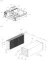
- FIG. 3 is a diagram showing a machine room and an air flow path section of a clothing processing equipment according to an embodiment of the present disclosure
- FIG. 4 is a diagram showing the evaporator 300 and the condenser 400 shown in FIG. 3 .
- the evaporator 300 and the condenser 400 may be installed inside the air flow path 150.
- the evaporator 300 may be connected to the drum outlet, and the condenser 400 may be connected to the drum inlet.
- the present disclosure may include a machine room 161 in which a compressor 163, an expansion valve, and a refrigerant pipe 165 are located.
- the machine room 161 may be arranged next to the air flow path 150.
- the high temperature and humidity air discharged from the drum 130 has a higher temperature than the refrigerant of the evaporator 300, as it passes through the evaporator 300, the heat of the air is absorbed by the refrigerant of the evaporator 300, thereby being condensed and generating condensed water. Accordingly, the moisture of the high temperature-humidity air is removed by the evaporator 300, and the condensed water can be collected into a separate condensed water tank (not shown) and drained.
- the heat source of the air absorbed in the evaporator 300 is moved to the condenser 400 via the refrigerant, and the compressor 163 may be located between the evaporator 300 and the condenser 400 to move the heat source from the evaporator 300 (low heat source portion) to the condenser 400 (high heat source portion).
- the evaporator 300 may be a fin & tube type heat exchanger.
- the fin & tube type is a type in which a plurality of flat fins are attached to a hollow tube, and the refrigerant flows along the inside of the tube, and the air can exchange heat with the refrigerant as it passes between the plurality of fins attached to the tube.
- the fin is used to expand the heat exchange area between the air and the refrigerant.
- the evaporator 300 may include a plurality of evaporation refrigerant tubes 310 through which refrigerant flows, and an evaporation fin 320 that conducts heat of the evaporation refrigerant.
- the evaporator 300 may include an evaporation inlet pipe 391 that supplies refrigerant to the evaporation refrigerant tube 310, and an evaporation outlet pipe 392 through which refrigerant is discharged from the evaporation refrigerant tube 310.
- the evaporation inlet pipe 391 is connected to the expansion valve 164 and the evaporation refrigerant tube 310, and the evaporation outlet pipe 392 is connected to the compressor 163 and the evaporation refrigerant tube 310.
- the detailed structure of the evaporator 300 is described later in FIG. 10 .
- the condenser 400 may include a microchannel type heat exchanger.
- the condenser 400 includes a condensation refrigerant tube 410 including a plurality of channels 410a through which refrigerant flows, and a condensation fin 420 for conducting heat of the condensation refrigerant tube 410.
- the condenser 400 may include a condensation inlet pipe 491 for supplying refrigerant to the condensation refrigerant tube 410, and a condensation outlet pipe 492 for discharging refrigerant from the condensation refrigerant tube 410.
- the condensation inlet pipe 491 is connected to the compressor 163 and the condensation refrigerant tube 410, and the condensation outlet pipe 492 is connected to the expansion valve 164 and the condensation refrigerant tube 410.
- the detailed structure of the condenser 400 is described later in FIGS. 5 to 9 .
- a micro-channel type heat exchanger is used for the condenser 400, the temperature of the air passing through the condenser 400 can be increased more than when a fin tube heat exchanger is used, and the air can be heated to a target temperature in a much shorter heat exchange time. Therefore, if a micro-channel type heat exchanger is used for the condenser 400, the drying efficiency of the clothing processing equipment can be improved.
- each channel 410a of the refrigerant tube of the condenser 400 is smaller than the cross-sectional area of the refrigerant tube of the evaporator 300.
- a fin tube heat exchanger is used rather than a micro-channel heat exchanger because a large amount of heat exchange is not required.
- the air flowing in the air flow path 150 exchanges heat with the evaporator 300 and then flows into the condenser 400. At this time, if the evaporator 300 and the condenser 400 are disposed too close together, the condensed water generated in the evaporator 300 flows into the condenser 400, thereby reducing the heat exchange efficiency of the condenser 400.
- the separation distance D1 between the evaporator 300 and the condenser 400 may be larger than the width W1 of the air flow direction of the evaporator 300.
- the width W1 of the airflow direction of the evaporator 300 may be larger than the width W2 of the airflow direction of the condenser 400.
- the height H1 of the evaporator 300 may be smaller than the height H2 of the condenser 400.
- the separation distance D1 of the condenser 400 may be larger than the sum of the width W1 of the airflow direction of the evaporator 300 and the width W2 of the airflow direction of the condenser 400.
- the separation distance D1 of the condenser 400 may be 100 mm to 250 mm.
- the separation distance D1 of the condenser 400 is larger than the sum of the width W1 of the air flow direction of the evaporator 300 and the width W2 of the air flow direction of the condenser 400, the condensed water generated in the evaporator 300 by the air flow falls into a space between the condenser 400 and the evaporator 300.
- the condensation inlet pipe 491 and the condensation outlet pipe 492 may be located in the same direction with respect to the condensation refrigerant tube 410. Specifically, the condensation inlet pipe 491 and the condensation outlet pipe 492 may extend from the condensation refrigerant tube 410 toward the machine room.
- the condensation inlet pipe 491 and the condensation outlet pipe 492 extend to the right from the condensation refrigerant tube 410.
- condensation inlet pipe 491 and the condensation outlet pipe 492 are located in the same direction with respect to the condensation refrigerant tube 410, a space for arranging the refrigerant pipe can be reduced, the length of the refrigerant pipe can be reduced, and a sufficient space for the air flow path 150 can be secured.
- An evaporation inlet pipe 391 and an evaporation outlet pipe 392 can be located in the same direction with respect to an evaporation refrigerant tube 310. Specifically, the evaporation inlet pipe 391 and the evaporation outlet pipe 392 can be extended from the evaporation refrigerant tube 310 toward the machine room.
- the evaporation inlet pipe 391 and the evaporation outlet pipe 392 are extended to the right from the evaporation refrigerant tube 310.
- a space for arranging the refrigerant pipe can be reduced, the length of the refrigerant pipe can be reduced, and sufficient space for the air path 150 can be secured.
- the evaporation inlet pipe 391, the evaporation outlet pipe 392, the condensation inlet pipe 491, and the condensation outlet pipe 492 can extend in the same direction from the air path 150.
- the evaporation inlet pipe 391, the evaporation outlet pipe 392, the condensation inlet pipe 491, and the condensation outlet pipe 492 extend in the right direction from the air path 150.
- the condenser 400 includes a heat exchanger.
- the condenser 400 means a heat exchanger.
- FIG. 5 is a perspective view showing the condenser 400 shown in FIG. 3 .
- the condenser 400 is a microchannel type heat exchanger.
- the condenser 400 is made of aluminum material.
- the condenser 400 may include a first heat exchange unit P1, a second heat exchange unit P2, and a third heat exchange unit P3. Unlike the present embodiment, the condenser 400 may have three or more heat exchange units that are stacked.
- the first heat exchange unit P1, the second heat exchange unit P2, and the third heat exchange unit P3 may be arranged to overlap with each other in the front-rear direction which is the air flow direction.
- the first heat exchange unit P1, the second heat exchange unit P2, and the third heat exchange unit P3 may be arranged to completely overlap in the front-rear direction or may be arranged to overlap in some area.
- the first heat exchange unit P1, the second heat exchange unit P2, and the third heat exchange unit P3 may be arranged along the air flow direction.
- the condenser 400 includes a first heat exchange unit P1, a second heat exchange unit P2 located to overlap with the first heat exchange unit P1 in the air flow direction, a third heat exchange unit P3 located to overlap the second heat exchange unit P2 in the air flow direction, a condensation inlet pipe 491 connected to the first heat exchange unit P1 to supply refrigerant, a condensation outlet pipe 492 connected to the third heat exchange unit P3 to discharge refrigerant, a first connection pipe 493 that connects the first heat exchange unit P1 and the second heat exchange unit P2, and allows the refrigerant to flow from the first heat exchange unit P1 to the second heat exchange unit P2, and a second connection pipe 494 that connects the second heat exchange unit P2 and the third heat exchange unit P3, and allows the refrigerant to flow from the second heat exchange unit P2 to the third heat exchange unit P3.
- the first heat exchange unit P1 is arranged to exchange heat with air that has been heat-exchanged with the second heat exchange unit P2, and the second heat exchange unit P2 is arranged to exchange heat with air that has been heat-exchanged with the third heat exchange unit P3. That is, air that has been heat-exchanged in the third heat exchange unit P3 is heat-exchanged in the second heat exchange unit P2, and then heat-exchanged in the first heat exchange unit P1.
- the first heat exchange unit P1, the second heat exchange unit P2, and the third heat exchange unit P3 are arranged on a path through which external air flows, and the external air is firstly heat-exchanged with the third heat exchange unit P3, secondly heat-exchanged with the second heat exchange unit P2, and thirdly heat-exchanged with the first heat exchange unit P1.
- the third heat exchange unit P3 may be located upstream of the air flow direction than the second heat exchange unit P2, and the second heat exchange unit P2 may be located upstream of the air flow direction than the first heat exchange unit P1.
- the third heat exchange unit P3 may be located closer to the suction path 151 through which air is flowed in than the second heat exchange unit P2, and the first heat exchange unit P1 may be located closer to the exhaust path 152 through which air is discharged than the second heat exchange unit P2.
- the first heat exchange unit P1 through which the high-temperature refrigerant flows is disposed in an area where the temperature of the outside air is high
- the third heat exchange unit P3 through which the low-temperature refrigerant flows is disposed in an area where the temperature of the outside air is low, so that the temperature of the refrigerant in each heat exchange unit and the temperature of the outside air are appropriately different, thereby improving the heat exchange efficiency of the condenser 400.
- the first heat exchange unit P1, the second heat exchange unit P2, and the third heat exchange unit P3 may include a plurality of refrigerant tubes 50 and a fin which is located between the refrigerant tubes 50 that are adjacent to each other to conduct heat.
- the first heat exchange unit P1, the second heat exchange unit P2, and the third heat exchange unit P3 are manufactured by stacking a plurality of refrigerant tubes 50.
- Each refrigerant tube 50 extends in a horizontal direction so that the refrigerant moves horizontally.
- the refrigerant tube 50 of the first heat exchange unit P1, the second heat exchange unit P2, and the third heat exchange unit P3 are arranged long in a horizontal direction (transverse direction) when the air flow direction is front-rear direction, and a plurality of refrigerant tubes 50 can be stacked vertically. As air passes through a space between the plurality of refrigerant tubes 50 stacked in a vertical direction (longitudinal direction), heat is exchanged with the refrigerant in the refrigerant tube 50.
- the plurality of refrigerant tubes 50 stacked vertically define a heat exchange surface together with the fin described below.
- FIG. 6 is a cross-sectional view of the refrigerant tube and the fin of the condenser shown in FIG. 3 .
- FIG. 6 illustrates the first heat exchange unit P1
- the structure of the refrigerant tube 50 and the fin of the second heat exchange unit P2 and the third heat exchange unit P3 are the same as that of the first heat exchange unit P1.
- the cross-sectional shape of the refrigerant tube 50 may be a rectangular shape that has a left-right direction length longer than an up-down direction length, and the cross-sectional shape of the microchannel 50a may be a rectangular shape.
- the microchannel 50a is usually stacked in a single row in a direction intersecting with the longitudinal direction of the refrigerant tube 50.
- a fin 60 transmits heat of the refrigerant tube 50.
- the fin 60 increases the contact area with air to improve heat dissipation performance.
- the fin 60 is arranged between adjacent refrigerant tubes 50.
- the fin 60 may have various shapes, but may be formed by bending a plate having the same width as the refrigerant tube 50.
- the fin 60 may be coated with a clad 601.
- the fin 60 may conduct heat by connecting two refrigerant tubes 50 that are stacked in the up-down direction.
- the fin 60 may be in direct contact with the refrigerant tube 50, or may be connected to the refrigerant tube 50 by a sacrificial sheet 90.
- the contact area between the fin 60 and the sacrificial sheet 90 becomes a U-shape or V-shape.
- the fin 60 and the refrigerant tube 50 are alternately stacked in the up-down direction, and have an arrangement in which the refrigerant tube 50 is located at the lowermost and uppermost ends.
- the refrigerant tube 50 located at the uppermost end is defined as a first refrigerant tube 50, 51, and the refrigerant tube 50 located below the first refrigerant tube 50, 51 is defined as a second refrigerant tube 50, 52
- the fin 60 between the first refrigerant tube 50, 51 and the second refrigerant tube 50, 52 may be defined as a first fin 60, 61.
- a n-th refrigerant tube and a n-th fin may be defined.
- the corrosion potential of the sacrificial sheet 90 may be lower than the corrosion potential of the refrigerant tube 50.
- the metal with the lower corrosion potential is corroded first, so that the sacrificial sheet 90 is corroded instead of the refrigerant tube 50, thereby preventing the refrigerant tube 50 from corroding and causing the refrigerant to leak out.
- the corrosion potential of the sacrificial sheet 90 may be lower than the corrosion potential of the fin 60. Even when only the refrigerant tube 50 is not corroded, the refrigerant leakage is prevented, so there is no problem. However, if the fin 60 is corroded, the flow of air is impeded and the refrigerant efficiency is reduced, so it is preferable that the corrosion potential of the sacrificial sheet 90 is lower than the corrosion potential of the fin 60.
- the corrosion potential of the sacrificial sheet 90 is lower than the corrosion potential of the fin 60, the sacrificial sheet 90 is corroded first instead of the fin 60, so that corrosion of the fin 60 can be prevented.
- the corrosion potential of the fin 60 may be lower than the corrosion potential of the refrigerant tube 50.
- the portion that is dangerous when corroded is the refrigerant tube 50. If the fin 60 corrodes, the efficiency is slightly reduced, but if the refrigerant tube 50 corrodes, the refrigerant leaks and the air conditioner does not operate, which is a big problem.
- the present disclosure makes the corrosion potential of the fin 60 to be lower than the corrosion potential of the refrigerant tube 50, thereby corroding the fin 60 before the refrigerant tube 50, and preventing corrosion of the refrigerant tube 50.
- the corrosion potential of the sacrificial sheet 90 may be lower than the corrosion potential of the refrigerant tube 50
- the corrosion potential of the sacrificial sheet 90 may be lower than the corrosion potential of the fin 60
- the corrosion potential of the fin 60 may be lower than the corrosion potential of the refrigerant tube 50.
- FIG. 7 is an enlarged view of a partial area of FIG. 6
- FIG. 8 is a perspective view of FIG. 7
- FIG. 9 is a diagram viewing FIG. 8 from the air flow direction.
- the fin 60 may be formed by bending a plurality of bodies.
- the fin 60 may include a plurality of first bodies 611 extending in the up-down direction, a plurality of second bodies 613 that extend in the up-down direction (based on FIG. 8 ) and are located between the plurality of first bodies 611, an upper body 615 connecting the upper end of the first body 611 and the upper end of the second body 613 that are adjacent to each other, and a lower body 617 connecting the lower end of the first body 611 and the lower end of the second body 613 that are adjacent to each other.
- first body 611 and the second body 613 may have an incline with respect to the up-down direction.
- the upper body 615 is connected to the lower end of the refrigerant tube 50 located at the upper portion among the adjacent refrigerant tubes 50, and the lower body 617 is connected to the upper end of the refrigerant tube 50 located at the upper portion among the adjacent refrigerant tubes 50.
- the upper body 615 of the first fin 60, 61 is connected to the lower end of the first refrigerant tube 51, and the lower body 617 of the first fin 60, 61 is connected to the upper end of the second refrigerant tube 52.
- the upper body 615 is located so as not to overlap the lower body 617 in the up-down direction.
- the upper body 615 and the lower body 617 are located alternately in the left-right direction.
- a flat portion 620, a first mountain portion 630, a second mountain portion 640, and a third mountain portion described below may be formed in the first body 611 and the second body 613.
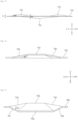
- FIG. 10 is a plan view of the fin shown in FIG. 8
- FIG. 11 is a side view of the fin shown in FIG. 10
- FIG. 12 is a cross-sectional view taken along line 12-12' of the fin shown in FIG. 10 .
- the fin extends in a first direction (front-rear direction). Therefore, the first direction means a longitudinal direction.
- the fin 60 includes a flat portion 620 defining a plane parallel to the first direction, a first mountain portion 630 having a step from the flat portion 620, and a second mountain portion 640 having a step from the flat portion 620.
- the flat portion 620 may be a portion having a step from the first mountain portion 630 and the second mountain portion 640. Specifically, the flat portion 620 is located lower than the first mountain portion 630 and the second mountain portion 640.
- the flat portion 620 may have various shapes, but may be a flat plate shape with respect to the first direction.
- the flat portion 620 is arranged to surround the first mountain portion 630 and the second mountain portion 640.
- the flat portion 620 is arranged close to the portion where the fin is bent, so that the rigidity of the fin can be improved.
- the flat portion 620 may be a plate shape in a longitudinal direction, and a portion of the flat portion 620 in the center of the flat portion 620 may be pressed and deformed to define a mountain portion.
- the mountain portion is located at the outer edge of the fin 60, there is a risk that the bent fin portions may be deformed.
- the distance D1 between the upper end of the flat portion 620 and each mountain portion may be greater than the distance D2 between the front end (or rear end) of the flat portion 620 and each mountain portion.
- the bending portion of the fin is the upper end and lower end of the flat portion 620, so that the bending portion of the fin is sufficiently separated, thereby not reducing the rigidity, and improving the heat exchange efficiency.
- the first mountain portion 630 and the second mountain portion 640 may be arranged symmetrically with respect to the center of the fin.
- the first mountain portion 630 and the second mountain portion 640 may be spaced apart from each other, or may be connected to each other.
- At least one end of the first mountain portion 630 and the second mountain portion 640 may be connected to the flat portion 620.
- the first mountain portion 630 and the second mountain portion 640 may be arranged along the longitudinal direction of the fin. That is, the first mountain portion 630 is located in front of the second mountain portion 640.
- one end of the first mountain portion 630 may be connected to one end of the second mountain portion 640.
- the first mountain portion 630 and the second mountain portion 640 may protrude in the same direction from the flat portion 620. Specifically, the first mountain portion 630 and the second mountain portion 640 protrude upward from the flat portion 620.
- the cross-sectional shape of the first mountain portion 630 and the second mountain portion 640 may be a curved or linear shape.
- the first mountain portion 630 may include a plurality of inclined surfaces having an incline in a first direction
- the second mountain portion 640 may include a plurality of inclined surfaces having an incline in the first direction
- the first mountain portion 630 may include a first inclined surface 631 having an incline in the first direction, a second inclined surface 632 that has an incline in the first direction and has one end connected to the first inclined surface 631, a third inclined surface 635 that has an incline in the first direction and is connected to the first inclined surface 631 and the second inclined surface 632, and a fourth inclined surface 634 that has an incline in the first direction and is connected to the first inclined surface 631 and the second inclined surface 632.
- the front end of the first inclined surface 631 is connected to the flat portion 620, the first inclined surface 631 is inclined upward from the front to the rear, and the second inclined surface 632 is inclined downward from the front to the rear.
- the rear end of the second inclined surface 632 is connected to the second mountain portion 640.
- the length D4 of the second inclined surface 632 is greater than the length D6 of the first inclined surface 631.
- the inclination angle of the first inclined surface 631 is greater than the inclination angle of the second inclined surface 632.
- the inclination angle of a fifth inclined surface 641 and the inclination angle of a sixth inclined surface 642 mean the inclination angle with respect to the flat portion 620.
- the left-right width of the first inclined surface 631 may become smaller as it progresses from the front to the rear.
- the left-right width of the second inclined surface 632 may become larger as it progresses from the front to the rear.
- the left-right width of the rear end of the first inclined surface 631 may be the same as the left-right width of the front end of the second inclined surface 632.
- the upper end of the third inclined surface 635 is connected to the flat portion 620, a part of the lower end of the third inclined surface 635 is connected to the first inclined surface 631, and another part of the lower end of the third inclined surface 635 is connected to the second inclined surface 632.
- the third inclined surface 635 is inclined upward from the right to the left.
- the lower end of the fourth inclined surface 634 is connected to the flat portion 620, a part of the upper end of the fourth inclined surface 634 is connected to the first inclined surface 631, and another part of the upper end of the fourth inclined surface 634 is connected to the second inclined surface 632.
- the fourth inclined surface 634 is inclined upward from the left to the right.
- the first mountain portion 630 may further include a first top portion 633 having the highest height in the first mountain portion 630.
- the first top portion 633 may be a portion where the first inclined surface 631 and the second inclined surface 632 are connected. Specifically, the first top portion 633 may be a portion where the rear end of the first inclined surface 631 and the front end of the second inclined surface 632 meet.
- the first top portion 633 may be extended in a direction intersecting with a first direction. Specifically, the first top portion 633 may be extended in the left-right direction.
- the first top portion 633 may have a line shape.
- the length D3 of the first top portion 633 in a second direction may be longer than the length of the first top portion 633 in the first direction.
- the first top portion 633 may be connected to the third inclined surface 635 and the fourth inclined surface 634. Both ends of the first top portion 633 in the first direction (front-rear direction) may be connected to the first inclined surface 631 and the second inclined surface 632, respectively, and both ends of the first top portion 633 in the second direction (left-right direction) intersecting with the first direction may be connected to the third inclined surface 635 and the fourth inclined surface 634, respectively.
- the second inclined surface 632 may be closer to the second mountain portion 640 than the first inclined surface 631.
- the second mountain portion 640 may have the same shape as the first mountain portion 630 and may be formed symmetrically with respect to the center of the fin.
- the second mountain portion 640 may include a fifth inclined surface 641 having an incline in the first direction, a sixth inclined surface 642 that has an incline in the first direction and has one end connected to the fifth inclined surface 641, a seventh inclined surface 645 that has an incline in the first direction and is connected to the fifth inclined surface 641 and the sixth inclined surface 642, and an eighth inclined surface 644 that has an incline in the first direction and is connected to the fifth inclined surface 641 and the sixth inclined surface 642.
- the front end of the fifth inclined surface 641 is connected to the first mountain portion 630, the fifth inclined surface 641 is inclined upward from the front to the rear, and the sixth inclined surface 642 is inclined downward from the front to the rear.
- the rear end of the sixth inclined surface 642 is connected to the flat portion 620.
- the length of the sixth inclined surface 642 is smaller than the length of the fifth inclined surface 641.
- the inclination angle of the fifth inclined surface 641 is smaller than the inclination angle of the sixth inclined surface 642.
- the inclination angle of the fifth inclined surface 641 and the inclination angle of the sixth inclined surface 642 mean the inclination angle with respect to the flat portion 620.
- the left-right width of the fifth inclined surface 641 may become smaller as it goes from the front to the rear.
- the left-right width of the sixth inclined surface 642 may become larger as it goes from the front to the rear.
- the left-right width of the rear end of the fifth inclined surface 641 may be the same as the left-right width of the front end of the sixth inclined surface 642.
- the upper end of the seventh inclined surface 645 is connected to the flat portion 620, a part of the lower end of the seventh inclined surface 645 is connected to the fifth inclined surface 641, and another part of the lower end of the seventh inclined surface 645 is connected to the sixth inclined surface 642.
- the seventh inclined surface 645 is inclined upward from the right to the left.
- the eighth inclined surface 644 has a lower end connected to the flat portion 620, a part of the upper end of the eighth inclined surface 644 is connected to the fifth inclined surface 641, and another part of the upper end of the eighth inclined surface 644 is connected to the sixth inclined surface 642.
- the eighth inclined surface 644 is inclined upward from the left to the right.
- the second mountain portion 640 may further include a second top portion 643 having the highest height in the second mountain portion 640.
- the second top portion 643 may be a portion where the fifth inclined surface 641 and the sixth inclined surface 642 are connected. Specifically, the second top portion 643 may be a portion where the rear end of the fifth inclined surface 641 and the front end of the sixth inclined surface 642 meet.
- the second top portion 643 may be extended in a direction intersecting with the first direction. Specifically, the second top portion 643 may be extended in the left-right direction. The second top portion 643 may have a line shape. The length D3 of the second top portion 643 in the second direction may be longer than the length of the second top portion 643 in the first direction.
- the second top portion 643 may be connected to the seventh inclined surface 645 and the eighth inclined surface 644. Both ends of the second top portion 643 in the first direction (front-rear direction) may be connected to the fifth inclined surface 641 and the sixth inclined surface 642, respectively, and both ends of the second top portion 643 in the second direction (left-right direction) intersecting with the first direction may be connected to the seventh inclined surface 645 and the eighth inclined surface 644, respectively.
- the fifth inclined surface 641 may be closer to the first mountain portion 630 than the sixth inclined surface 642.
- a bottom portion may be located between the first top portion 633 and the second top portion 643.
- the bottom portion may be a portion where the rear end of the second inclined surface 632 and the front end of the fifth inclined surface 641 meet.
- the bottom portion may extend in a left-right direction in a line shape.
- the bottom portion may be located at the same height as the flat portion 620 or at a higher height than the flat portion 620.
- the bottom portion may be the lowermost portion among the first mountain portion 630 and the second mountain portion 640.
- the height H1 of the first mountain portion 630 or the second mountain portion 640 may be greater than the thickness T1 of the flat portion 620.
- the length D3 of the first top portion 633 in the second direction may be greater than the height H1 of the first mountain portion 630 or the height H1 of the second mountain portion 640.
- the length L of the first body 611 (or fin) may be 1.7 to 2.5 times the width W of the first body 611 (or fin).
- the width D7 of the mountain portion may be 0.6 to 0.9 times the width W of the first body 611 (or fin).
- the first mountain portion 630 may include various shapes having a vertex protruding in a direction intersecting with the first direction
- the second mountain portion 640 may include various shapes having a vertex protruding in an intersecting direction.
- the first mountain portion 630 may have a hemispherical shape that protrudes in a direction intersecting with the first direction.
- FIG. 13 is a partial diagram of a condenser according to another embodiment of the present disclosure
- FIG. 14 is a plan view of the fin shown in FIG. 13
- FIG. 15 is a side view of the fin shown in FIG. 14
- FIG. 16 is a cross-sectional view taken along line 16-16' of the fin shown in FIG. 14
- FIG. 17 is a cross-sectional view taken along line 17-17' of the fin shown in FIG. 14 .
- the heat exchanger according to another embodiment has a difference in the structure of the flat portion 720 and the mountain portion formed in the fin, in comparison with the embodiment of FIGS. 10 to 12 .
- Another fin according to another embodiment includes a flat portion 720, a first mountain portion 730 protruding than the flat portion 720 in a second direction intersecting with a first direction, a second mountain portion 740 protruding than the flat portion 720 in the second direction, and a third mountain portion 750 protruding than the flat portion 720 in a direction opposite to the second direction between the first mountain portion 730 and the second mountain portion 740.
- the first mountain portion 730 and the second mountain portion 740 may be arranged symmetrically with respect to the third mountain portion 750.
- the flat portion 720 may be arranged to surround the first mountain portion 730, the second mountain portion 740, and the third mountain portion 750.
- One end of the third mountain portion 750 may be connected to the first mountain portion 730, and the other end of the third mountain portion 750 may be connected to the second mountain portion 740.
- the first mountain portion 730 may include a plurality of inclined surfaces having an incline with respect to the first direction
- the second mountain portion 740 may include a plurality of inclined surfaces having an incline with respect to the first direction
- partial inclined surface of the first mountain portion 730 and partial inclined surface of the second mountain portion 740 may define the third mountain portion 750.
- a part of the inclined surface may be located at the same height as the flat portion 720.
- the first mountain portion 730, the second mountain portion 740, and the third mountain portion 750 can be formed separately.
- a part of the inclined surface of the first mountain portion 730 and a part of the inclined surface of the second mountain portion 740 define the third mountain portion 750.
- the fin 60A may include a first inclined surface 731 having an incline in the first direction, a second inclined surface 732 that has an incline in the first direction and has one end connected to the first inclined surface 731, a third inclined surface 735 that has an incline in the first direction and is connected to the first inclined surface 731 and the second inclined surface 732, a fourth inclined surface 734 that has an incline in the first direction and is connected to the first inclined surface 731 and the second inclined surface 732, a fifth inclined surface 741 that has one end having an incline in the first direction connected to the second inclined surface 732, a sixth inclined surface 742 that has an incline in the first direction and has one end connected to the fifth inclined surface 741, a seventh inclined surface 745 that has an incline in the first direction and is connected to the fifth inclined surface 741 and the sixth inclined surface 742, an eighth inclined surface 744 that has an incline in the first direction and is connected to the fifth inclined surface 741 and the sixth inclined surface 742,
- the front end of the first inclined surface 731 is connected to the flat portion 720, the first inclined surface 731 is inclined upward from the front to the rear, and the second inclined surface 732 is inclined downward from the front to the rear.
- the second inclined surface 732 has a rear end connected to the fifth inclined surface 741.
- the length of the second inclined surface 732 in the front-rear direction is greater than the length of the first inclined surface 731 in the front-rear direction.
- the inclination angle of the first inclined surface 731 is greater than the inclination angle of the second inclined surface 732.
- the second inclined surface 732 may have a front end that is the first top portion 733 of the first mountain portion 730, and a rear end of the second inclined surface 732 may be located below the flat portion 720. That is, the rear end of the second inclined surface 732 is the lowermost location in the fin, and is defined as the third top portion 755 of the third mountain portion 750.
- the left-right width of the first inclined surface 731 may become smaller as it goes from the front to the rear.
- the left-right width of the second inclined surface 732 may become larger as it goes from the front to the rear.
- the left-right width of the rear end of the first inclined surface 731 may be the same as the left-right width of the front end of the second inclined surface 732.
- a part of the upper end of the third inclined surface 735 is connected to the flat portion 720, and another part of the upper end of the third inclined surface 735 is connected to the ninth inclined surface 752.
- the front end of the upper end of the third inclined surface 735 is connected to the flat portion 720, and the rear end of the upper end of the third inclined surface 735 is connected to the ninth inclined surface 752.
- a part of the lower end of the third inclined surface 735 is connected to the first inclined surface 731, and another part of the lower end of the third inclined surface 735 is connected to the second inclined surface 732.
- the third inclined surface 735 is inclined upward from the right to the left.
- a part of the lower end of the fourth inclined surface 734 is connected to the flat portion 720, and another part of the lower end of the fourth inclined surface 734 is connected to the tenth inclined surface 751.
- a part of the upper end of the fourth inclined surface 734 is connected to the first inclined surface 731, and another part of the upper end of the fourth inclined surface 734 is connected to the second inclined surface 732.
- the fourth inclined surface 734 is inclined upward from the left to the right.
- the front end of the fifth inclined surface 741 is connected to the second inclined surface 732, the fifth inclined surface 741 is inclined upward from the front to the rear, and the sixth inclined surface 742 is inclined downward from the front to the rear.
- the rear end of the sixth inclined surface 742 is connected to the flat portion 720.
- the length of the sixth inclined surface 742 is smaller than the length of the fifth inclined surface 741.
- the inclination angle of the fifth inclined surface 741 is smaller than the inclination angle of the sixth inclined surface 742.
- the left-right width of the fifth inclined surface 741 may become smaller as it goes from the front to the rear.
- the left-right width of the sixth inclined surface 742 may become larger as it goes from the front to the rear.
- the left-right width of the rear end of the fifth inclined surface 741 may be the same as the left-right width of the front end of the sixth inclined surface 742.
- a part of the upper end of the seventh inclined surface 745 is connected to the flat portion 720, another part of the upper end of the seventh inclined surface 745 is connected to the ninth inclined surface 752, a part of the lower end of the seventh inclined surface 745 is connected to the fifth inclined surface 741, and another part of the lower end of the seventh inclined surface 745 is connected to the sixth inclined surface 742.
- the seventh inclined surface 745 is inclined upward from the right to the left.
- a part of the lower end of the eighth inclined surface 744 is connected to the flat portion 720, another part of the lower end of the eighth inclined surface 744 is connected to the tenth inclined surface 751, another part of the upper end of the eighth inclined surface 744 is connected to the fifth inclined surface 741, and another part of the upper end of the eighth inclined surface 744 is connected to the sixth inclined surface 742.
- the eighth inclined surface 744 is inclined upward from the left to the right.
- the upper end of the ninth inclined surface 752 is connected to the flat portion 720, the front portion of the lower end of the ninth inclined surface 752 is connected to the third inclined surface 735, and the rear portion of the lower end of the ninth inclined surface 752 is connected to the seventh inclined surface 745.
- the center of the lower end of the ninth inclined surface 752 may be connected to the boundary (the third top portion 755) between the second inclined surface 732 and the fifth inclined surface 741.
- the ninth inclined surface 752 may be inclined downward as it goes toward the left.
- the lower end of the tenth inclined surface 751 is connected to the flat portion 720, the front portion of the upper end of the tenth inclined surface 751 is connected to the fourth inclined surface 734, and the rear portion of the upper end of the tenth inclined surface 751 is connected to the eighth inclined surface 744.
- the center of the upper end of the tenth inclined surface 751 may be connected to the boundary (the third top portion 755) between the second inclined surface 732 and the fifth inclined surface 741.
- the tenth inclined surface 751 may be inclined downward as it goes toward the right.
- the inclination angle of the third inclined surface 735 and the fourth inclined surface 734 may be the same.
- the inclination angle O1 of the third inclined surface 735 and the fourth inclined surface 734 may be smaller than the inclination angle 02 of the ninth inclined surface 752 and the tenth inclined surface 751.
- the inclination angle of the ninth inclined surface 752 and the inclination angle of the tenth inclined surface 751 may be the same.
- the inclination angle refers to the angle formed by the flat portion 720 and the inclined surface.
- the first top portion 733 may be a portion where the first inclined surface 731 and the second inclined surface 732 are connected. Specifically, the first top portion 733 may be a portion where the rear end of the first inclined surface 731 and the front end of the second inclined surface 732 meet.
- the first top portion 733 may be extended in a direction intersecting with the first direction. Specifically, the first top portion 733 may be extended in the left-right direction. The first top portion 733 may have a line shape. The length of the first top portion 733 in the second direction may be longer than the length of the first top portion 733 in the first direction.
- the first top portion 733 may be connected to the third inclined surface 735 and the fourth inclined surface 734. Both ends of the first top portion 733 in the first direction (front-rear direction) may be connected to the first inclined surface 731 and the second inclined surface 732, respectively, and both ends of the first top portion 733 in the second direction (left-right direction) intersecting with the first direction may be connected to the third inclined surface 735 and the fourth inclined surface 734, respectively.
- the second inclined surface 732 may be closer to the second mountain portion 740 than the first inclined surface 731.
- the second mountain portion 740 may have the same shape as the first mountain portion 730 and may be formed symmetrically with respect to the center of the fin.
- the second mountain portion 740 may further include a second top portion 743 having the highest height in the second mountain portion 740.
- the second top portion 743 may be a portion where the fifth inclined surface 741 and the sixth inclined surface 742 are connected.
- the second top portion 743 may be a portion where the rear end of the fifth inclined surface 741 and the front end of the sixth inclined surface 742 meet.
- the second top portion 743 may extend in a direction intersecting with the first direction. Specifically, the second top portion 743 may extend in the left-right direction. The second top portion 743 may have a line shape. The length D3 of the second top portion 743 in the second direction may be longer than the length of the second top portion 743 in the first direction.
- the second top portion 743 may be connected to the seventh inclined surface 745 and the eighth inclined surface 744. Both ends of the second top portion 743 in the first direction (front-rear direction) may be connected to the fifth inclined surface 741 and the sixth inclined surface 742, respectively, and both ends of the second top portion 743 in the second direction (left-right direction) intersecting with the first direction may be connected to the seventh inclined surface 745 and the eighth inclined surface 744, respectively.
- the third mountain portion 750 may include a third top portion 755.
- the third top portion 755 may be located between the first top portion 733 and the second top portion 743.
- the third mountain portion 750 may be defined as an inclined surface located at a lower height than the flat portion 720 among the inclined surfaces
- the first mountain portion 730 may be an inclined surface located in the front among the inclined surfaces located at a higher height than the flat portion 720 among the inclined surfaces
- the second mountain portion 740 may be an inclined surface located in the rear among the inclined surfaces located at a higher height than the flat portion 720 among the inclined surfaces.
- the third mountain portion 750 is defined as the rear end of the second inclined surface 732, the rear end of the third inclined surface 735, the rear end of the fourth inclined surface 734, the front end of the fifth inclined surface 741, the front end of the sixth inclined surface 742, the front end of the eighth inclined surface 744, a part of the ninth inclined surface 752, and a part of the tenth inclined surface 751.
- the first mountain portion 730 is defined as the first inclined surface 731, the front end of the second inclined surface 732, a part of the third inclined surface 735, and a part of the fourth inclined surface 734.
- the first mountain portion 730 is defined as the sixth inclined surface 742, the rear end of the fifth inclined surface 741, a part of the seventh inclined surface 745, and a part of the eighth inclined surface 744.
- the third top portion 755 may be a portion where the rear end of the second inclined surface 732 and the front end of the fifth inclined surface 741 meet.
- the third top portion 755 may extend in a line shape in the left-right direction.
- the third top portion 755 is located at a lower height than the flat portion 720.
- the height H2 of the first mountain portion 730 or the second mountain portion 740 may be greater than the thickness T1 of the flat portion 720.
- the length of the first top portion 733 in the second direction may be greater than the height H2 of the first mountain portion 730 or the height H2 of the second mountain portion 740.
- the height H2 of the first mountain portion 730 or the second mountain portion 740 may be smaller than the height H3 of the third mountain portion 750.
- the height H3 of the third mountain portion 750 may be 1.8 to 2.2 times greater than the height H2 of the first mountain portion 730 or the second mountain portion 740.
- the first top portion 733 may be referred to as a first top line, the second top portion 743 as a second top line, and the third top portion 755 as a third top line.
- the first top line protrudes upwardly than the flat portion 720
- the second top line protrudes upwardly from the flat portion 720
- the third top line protrudes downwardly from the flat portion 720 at between the first top line and the second top line.
- the first top line and the third top line may be connected to each other by an inclined surface, and the second top line and the third top line may be connected to each other by an inclined surface.
- first mountain portion 730 and the second mountain portion 740 may have various shapes having a peak higher than the flat portion 720
- the third mountain portion 750 may have various shapes having a peak lower than the flat portion 720.
- first mountain portion 730 and the second mountain portion 740 may have a hemispherical shape protruding higher from the flat portion 720
- third mountain portion 750 may have a hemispherical shape protruding lower from the flat portion 720.
- the clothing processing equipment and heat exchanger of the present disclosure have one or more of the following effects.
- the present disclosure provides an advantage in that the fin of a micro heat exchanger used in the clothing processing equipment include two protrusions protruding from the fin, and the two protrusions are arranged along the air flow direction, so that the flow path of air flowing between the fins becomes longer, and the contact time between the air and the fin increases. Accordingly, the heat exchange efficiency is improved, and even if tint is flowed in between the fins spaced apart from each other, it is discharged without being caught by the protrusions.
- the present disclosure provides an advantage in that the fin of a micro heat exchanger used in the clothing processing equipment include two protrusions protruding from the fin and one protrusion protruding in the opposite direction to the two protrusions at between the two protrusions, and the three protrusions are arranged along the air flow direction, so that the flow path of air flowing between the fins becomes longer. Accordingly, the contact time between the air and the fins increases, so that the heat exchange efficiency is improved, and even if tint is flowed in between the fins spaced apart from each other, it is discharged without being caught by the protrusions, and even if it is protruded to only one side, it prevents the rigidity of the fins from being reduced.
- the present disclosure includes aluminum in the fins of the heat exchanger, thereby being resistant to corrosion.
- the present disclosure provides an advantage in that a microchannel heat exchanger is used as a condenser and a fin-tube heat exchanger is used as an evaporator in the machine room of the clothing processing equipment, so that a fin-tube heat exchanger having a low manufacturing cost is used for the evaporator as the evaporator requires relatively little energy, and a microchannel heat exchanger is used for the condenser which requires a large amount of heat to reheat the air in the air flow path and supply it to a tub, thereby improving heat exchange performance, reducing airflow resistance, and lowering the manufacturing cost.
Landscapes
- Engineering & Computer Science (AREA)
- Physics & Mathematics (AREA)
- Thermal Sciences (AREA)
- Mechanical Engineering (AREA)
- General Engineering & Computer Science (AREA)
- Geometry (AREA)
- Heat-Exchange Devices With Radiators And Conduit Assemblies (AREA)
Abstract
A heat exchanger of the present disclosure includes: a plurality of refrigerant tubes through which refrigerant flows; and a fin which is arranged between adjacent refrigerant tubes, conducts heat, and extends in a first direction, wherein the fin includes: a flat portion defining a surface parallel to the first direction; a first mountain portion having a step from the flat portion; and a second mountain portion having a step from the flat portion, wherein the first mountain portion and the second mountain portion are arranged symmetrically with respect to a center of the fin.
Description
- This disclosure relates to a heat exchanger having excellent heat exchange efficiency without tint or foreign matter being caught between fins.
- In general, a heat exchanger can be used as a condenser or evaporator in a refrigeration cycle device consisting of a compressor, a condenser, an expansion device, and an evaporator.
- In addition, a heat exchanger is installed in vehicles, refrigerators, and clothing processing equipments to exchange heat between refrigerant and air.
- In general, a clothing processing equipment is a device that evaporates moisture contained in laundry by blowing hot air generated by a heater into the inside of a drum to dry laundry.
- Depending on a method of processing the moist air that passed through a drum after drying a laundry, a clothing processing equipment can be classified into an exhaust type clothing processing equipment and a condensation type clothing processing equipment.
- The exhaust type clothing processing equipment exhausts the humid air passed through a drum to the outside of the clothing processing equipment. The condensation type clothing processing equipment does not exhaust the humid air passed through a drum to the outside of the clothing processing equipment, but circulates it, and cools the humid air to below a dew point temperature through a condenser to condense the moisture contained in the humid air.
- The condensation type clothing processing equipment heats the condensed water condensed in the condenser by a heater before resupplying it to a drum, and then flows the heated air into the drum. Here, the humid air is cooled during the condensation process, so that a loss of thermal energy contained in the air occurs, and a separate heater, etc., is required to heat it to the temperature required for drying.
- The exhaust-type clothing processing equipment also needs to discharge a high-temperature humid air to the outside and bring in a room temperature outside air to heat it to a required temperature level through a heater or the like. In particular, as drying progresses, the humidity of the air discharged from a drum outlet decreases, thereby losing the heat of the air that is discharged to the outside without being used to dry a drying target in a drum, so that the thermal efficiency is reduced.
- Therefore, recently, a clothing processing equipment having a heat pump cycle that can increase energy efficiency by recovering the energy discharged from a drum and using it to heat the air flowing into the drum has been introduced.
- The condensation type clothing processing equipment of Patent Document 1 (
Korean Publication No. 2016-0069333 drum 1 into which a drying target flows, a circulation duct 2 providing a path for air to circulate through thedrum 1, a circulation fan 3 for flowing a circulating air along the circulation duct 2, and a heat pump cycle 4 equipped with an evaporator 5 and a condenser 6 that are installed in series in the circulation duct 2 so that the air circulating along the circulation duct 2 passes through. - The heat pump cycle 4 may be equipped with a circulation pipe forming a circulation path for refrigerant to circulate through the evaporator 5 and the condenser 6, and a compressor 7 and an
expansion valve 8 that are installed in the circulation pipe between the evaporator 5 and the condenser 6. - The heat pump cycle 4, configured as described above, transmits the heat energy of the air passed through the
drum 1 to the refrigerant through the evaporator 5, and then transmits the heat energy of the refrigerant to the air flowing into thedrum 1 through the condenser 6. - Here, one of the evaporator and the condenser uses a general microchannel heat exchanger, and the fins of the microchannel are formed with a louver to increase heat exchange efficiency. However, since such a louver has many shapes that are open in the direction of air flow, there is a problem in that small pieces of clothing (tints) are get caught in the louver, thereby hindering the air flow and reducing the heat exchange efficiency.
- In the case of Patent Document 2(
Korean Patent Publication No. 10-2391896 Korean Patent Publication No. 10-2391896 - The disclosure has been made in view of the above problems, and may provide a heat exchanger that suppresses tint from being caught in a fin of a microchannel condenser in a machine room of a clothing processing equipment and improves heat exchange efficiency.
- The disclosure may further provide a heat exchanger that suppresses tint from being caught in a fin of a microchannel condenser in a machine room of a clothing processing equipment, improves the reliability of the heat exchanger, and improves the rigidity of the fin.
- The disclosure may further provide a clothing processing equipment that suppresses tint from being caught in a fin of a microchannel condenser in a machine room of a clothing processing equipment and improves heat exchange efficiency.
- The disclosure may further provide a clothing processing equipment that simultaneously uses a microchannel condenser and a fin-tube evaporator in a machine room of a clothing processing equipment, improves heat exchange performance, and reduces airflow resistance.
- The problems of the present disclosure are not limited to the problems mentioned above, and other problems not mentioned can be clearly understood by those skilled in the art from the description below.
- The heat exchanger according to the present disclosure includes two mountain portions in the fin, and two mountain portions are arranged symmetrically with respect to the center of the fin.
- In addition, the heat exchanger according to another embodiment of the present disclosure includes three mountain portions in the fin, and two mountain portions protrude in the opposite direction to the remaining one mountain portion and are arranged symmetrically with respect to the center of the fin.
- In accordance with an aspect of the present disclosure, a heat exchanger includes: a plurality of refrigerant tubes through which refrigerant flows; and a fin which is arranged between adjacent refrigerant tubes, conducts heat, and extends in a first direction, in which the fin includes: a flat portion defining a surface parallel to the first direction; a first mountain portion having a step from the flat portion; and a second mountain portion having a step from the flat portion, in which the first mountain portion and the second mountain portion are arranged symmetrically with respect to a center of the fin.
- The flat portion is arranged to surround the first mountain portion and the second mountain portion.
- The first mountain portion and the second mountain portion protrude in the same direction from the flat portion.
- One end of the first mountain portion is connected to one end of the second mountain portion.
- The first mountain portion includes a plurality of inclined surfaces having an incline with respect to the first direction.
- The second mountain portion includes a plurality of inclined surfaces having an incline with respect to the first direction.
- The first mountain portion includes: a first inclined surface having an incline with respect to the first direction; a second inclined surface which has an incline with respect to the first direction, and has one end connected to the first inclined surface; a third inclined surface which has an incline in the first direction, and is connected to the first inclined surface and the second inclined surface; and a fourth inclined surface which has an incline in the first direction, and is connected to the first inclined surface and the second inclined surface.
- In the first direction, a length of the second inclined surface is longer than a length of the first inclined surface.
- The first mountain portion further includes a first top portion having the highest height in the first mountain portion, in which the first top portion is a portion connecting the first inclined surface and the second inclined surface, and extends in a direction intersecting with the first direction.
- The first top portion is connected to the third inclined surface and the fourth inclined surface, both ends of the first top portion in the first direction are connected to the first inclined surface and the second inclined surface, respectively, and both ends of the first top portion in a second direction intersecting with the first direction are connected to the third inclined surface and the fourth inclined surface, respectively.
- A length of the first top portion in the second direction is longer than a length of the first top portion in the first direction.
- The second inclined surface is located closer to the second mountain portion than the first inclined surface.
- A height of the first mountain portion or the second mountain portion is greater than a thickness value of the flat portion.
- The length of the first top portion in the second direction is greater than a height of the first mountain portion or a height of the second mountain portion.
- An inclination angle of the first inclined surface is greater than an inclination angle of the second inclined surface.
- In addition, in accordance with another aspect of the present disclosure, a heat exchanger includes: a plurality of refrigerant tubes through which refrigerant flows; and a fin which is arranged between adjacent refrigerant tubes, conducts heat, and extends in a first direction, in which the fin includes: a flat portion defining a surface parallel to the first direction; a first mountain portion protruding in a second direction intersecting with the first direction from the flat portion; a second mountain portion protruding in the second direction from the flat portion; and a third mountain portion protruding in a direction opposite to the second direction from the flat portion at between the first mountain portion and the second mountain portion, in which the first mountain portion and the second mountain portion are arranged symmetrically with respect to the third mountain portion.
- The flat portion is arranged to surround the first mountain portion, the second mountain portion, and the third mountain portion.
- One end of the third mountain portion is connected to the first mountain portion, and the other end of the third mountain portion is connected to the second mountain portion.
- The first mountain portion includes a plurality of inclined surfaces having an incline with respect to the first direction, in which the second mountain portion includes a plurality of inclined surfaces having an incline with respect to the first direction, in which a partial inclined surface of the first mountain portion and a partial inclined surface of the second mountain portion define the third mountain portion.
- In addition, in accordance with another aspect of the present disclosure, a heat exchanger includes: a plurality of refrigerant tubes through which refrigerant flows; and a fin which is arranged between adjacent refrigerant tubes, conducts heat, and extends in a first direction, in which the fin includes: a flat portion defining a surface parallel to the first direction; a first top line protruding in a direction intersecting with the first direction from the flat portion; a second top line protruding in a direction intersecting with the first direction from the flat portion; and a third top line protruding in a direction from the flat portion at between the first top line and the second top line, in which the first top line and the third top line are connected to each other by an inclined surface, the second top line and the third top line are connected to each other by an inclined surface, and the third top line protrudes from the flat portion in a direction opposite to the first top line and the second top line.
- The above and other objects, features and advantages of the present disclosure will be more apparent from the following detailed description in conjunction with the accompanying drawings, in which:
-
FIG. 1 is a schematic diagram showing the flow of air and refrigerant in a clothing processing equipment according to an embodiment of the present disclosure; -
FIG. 2 is a schematic diagram showing the configuration of a clothing processing equipment according to an embodiment of the present disclosure; -
FIG. 3 is a diagram showing a machine room and an air passage portion of a clothing processing equipment according to an embodiment of the present disclosure; -
FIG. 4 is a diagram showing an evaporator and a condenser shown inFIG. 3 ; -
FIG. 5 is a perspective view showing a condenser shown inFIG. 3 ; -
FIG. 6 is a cross-sectional view showing the refrigerant tube and fin of the condenser shown inFIG. 3 ; -
FIG. 7 is an enlarged view of a partial area ofFIG. 6 ; -
FIG. 8 is a perspective view ofFIG. 7 ; -
FIG. 9 is a diagram viewingFIG. 8 from the air flow direction; -
FIG. 10 is a plan view of the fin shown inFIG. 8 ; -
FIG. 11 is a side view of the fin shown inFIG. 10 ; -
FIG. 12 is a cross-sectional view taken along line 12-12' of the fin shown inFIG. 10 ; -
FIG. 13 is a partial diagram of a condenser according to another embodiment of the present disclosure; -
FIG. 14 is a plan view of the fin shown inFIG. 13 ; -
FIG. 15 is a side view of the fin shown inFIG. 14 ; -
FIG. 16 is a cross-sectional view taken along line 16-16' of the fin shown inFIG. 14 ; and -
FIG. 17 is a cross-sectional view taken along line 17-17' of the fin shown inFIG. 14 . - Advantages and features of the present invention and methods for achieving those of the present invention will become apparent upon referring to embodiments described later in detail with reference to the attached drawings. However, embodiments are not limited to the embodiments disclosed hereinafter and may be embodied in different ways. The embodiments are provided for perfection of disclosure and for informing persons skilled in this field of art of the scope of the present invention. The same reference numerals may refer to the same elements throughout the specification.
- Spatially-relative terms such as "below", "beneath", "lower", "above", or "upper" may be used herein to describe one element's relationship to another element as illustrated in the Figures. It will be understood that spatially-relative terms are intended to encompass different orientations of the device in addition to the orientation depicted in the Figures. For example, if the device in one of the figures is turned over, elements described as "below" or "beneath" other elements would then be oriented "above" the other elements. The exemplary terms "below" or "beneath" can, therefore, encompass both an orientation of above and below. Since the device may be oriented in another direction, the spatially-relative terms may be interpreted in accordance with the orientation of the device.
- The terminology used in the present invention is for the purpose of describing particular embodiments only and is not intended to limit the disclosure. As used in the disclosure and the appended claims, the singular forms "a", "an" and "the" are intended to include the plural forms as well, unless context clearly indicates otherwise. It will be further understood that the terms "comprises" and/or "comprising," when used in this specification, specify the presence of stated features, integers, steps, operations, elements, and/or components, but do not preclude the presence or addition of one or more other features, integers, steps, operations, elements, components, and/or groups thereof.
- Unless otherwise defined, all terms (including technical and scientific terms) used herein have the same meaning as commonly understood by one of ordinary skill in the art. It will be further understood that terms, such as those defined in commonly used dictionaries, should be interpreted as having a meaning that is consistent with their meaning in the context of the relevant art and the present invention, and will not be interpreted in an idealized or overly formal sense unless expressly so defined herein.
- In the drawings, the thickness or size of each layer is exaggerated, omitted, or schematically illustrated for convenience of description and clarity. Also, the size or area of each constituent element does not entirely reflect the actual size thereof.
- Hereinafter, exemplary embodiments of the present invention will be described with reference to the accompanying drawings.
-
FIG. 1 is a schematic diagram showing the flow of air and refrigerant in a clothing processing equipment according to an embodiment of the present disclosure, andFIG. 2 is a schematic diagram showing a configuration of a clothing processing equipment according to an embodiment of the present disclosure. - Referring to
FIG. 1 and FIG. 2 , aclothing processing equipment 100 according to the present disclosure is an example of a drum-type dryer, and may be configured to include acabinet 110, adrum 130, a driving unit (not shown), ablower fan 170, and aheat pump 160, and the air of thedrum 130 is connected to theheat pump 160 by anair path 150. - Here, the
cabinet 110 may include adoor 112 provided on a front side to insert clothing while forming an outer shape of a product, and a base 114 on which an internal configuration of theclothing processing equipment 100 is installed. - Meanwhile, the
drum 130 may rotate around a rotation axis that is arranged horizontally or inclined at a certain angle inside the cabinet. Meanwhile, thedrum 130 has a hollow cylindrical shape, and provides an accommodation space for drying clothing, which are drying target, by putting the clothing into the space. - The
drum 130 is formed in a cylindrical shape having front and rear sides that are open. Thedrum 130 has afront support portion 132 that rotatably supports thedrum 130 at a front side. In addition, thedrum 130 has arear support portion 133 that rotatably supports thedrum 130 at a rear side. - In addition, a
front roller 142 and arear roller 143 in the form of roller that rotatably support thedrum 130 may be additionally provided at the front and rear lower portions of thedrum 130. That is, thefront support portion 132 and therear support portion 133 block the front and rear surfaces of thedrum 130 to form a drying space for drying target, and at the same time, serve to support the front and rear ends of thedrum 130. - Meanwhile, an inlet 132b for inserting the drying target into the
drum 130 is formed in thefront support portion 132, and the inlet is selectively opened and closed by thedoor 112. In addition, anair discharge port 132a to which anair path 150 described later is connected is located at the lower portion of thefront support portion 132. Asuction port 151 ofair path 150 described later is provided in theair discharge port 132a to communicate. - In addition, an air inlet 133a formed with a plurality of holes is formed in the
rear support portion 133 so that air is supplied to thedrum 130. The air inlet 133a is provided so that an exhaust path 152 of theair path 150 described later is communicated. - Here, in order to efficiently dry the clothing, which are the objects to be dried, a lifter 131a for tumbling the clothing that is put in may be further provided on the inner surface of the
drum 130. - In addition, a driving unit provides rotational power by using a motor (not shown), and the output shaft of the motor and the
drum 130 are connected by a power transmission means such as a belt, and the rotational power of the motor is transmitted to thedrum 130, thereby rotating thedrum 130. - In addition, the
air path 150 may be connected to thedrum 130 to form a closed loop for air circulation. For example, theair path 150 may be formed in the form of duct. Thesuction path 151 for air discharge is formed at the lower portion of thefront support portion 132 of thedrum 130, and the exhaust path 152 for air supply is formed at therear support portion 133 of thedrum 130. - Meanwhile, the
blower fan 170 may be installed inside theair path 150 extending from thesuction path 151 to anevaporator 300 of theheat pump 160, or installed inside theair path 150 extending from thecondenser 400 of theheat pump 160 to the exhaust path 152. - Here, the
blower fan 170 may be driven by a separate fan motor, and may apply power to the air to pass it through the inside of thedrum 130, and may circulate the air discharged from thedrum 130 back into thedrum 130. - In addition, a lint filter 162 (see
FIG. 3 ) for filtering a lint in the circulating air is installed in thesuction path 151. Thelint filter 162 may capture the lint contained in the air as the air sucked from thedrum 130 passes through thesuction path 151. - Therefore, the clothing (also called 'cloth') evaporates moisture by a hot air supplied into the
drum 130, and the air passing through thedrum 130 is discharged from thedrum 130 while containing the moisture evaporated from the clothing. The high-temperature and humid air discharged from thedrum 130 moves along theair path 150, receives heat from theheat pump 160 to be heated, and then is circulated to thedrum 130. - Meanwhile, the
heat pump 160 is configured to include anevaporator 300, acompressor 163, acondenser 400, and anexpansion valve 164. Theheat pump 160 may use a refrigerant as a working fluid. The refrigerant moves along arefrigerant pipe 165, and therefrigerant pipe 165 forms a closed loop for the circulation of the refrigerant. Theevaporator 300, thecompressor 163, thecondenser 400, and theexpansion valve 164 are connected by therefrigerant pipe 165, so that the refrigerant passes through theevaporator 300, thecompressor 163, thecondenser 400, and theexpansion valve 164 in sequence. - Here, the
evaporator 300 is installed in theair path 150 so as to be connected to a drum outlet, and heat-exchanges the air discharged from the drum outlet with the refrigerant, thereby recovering the heat of the air discharged from thedrum 130 without discharging it to the outside of a dryer. - In addition, the
condenser 400 is installed in theair path 150 so as to be connected to a drum inlet, and heat-exchanges the air passing through theevaporator 300 with the refrigerant, thereby dissipating the heat of the refrigerant absorbed in theevaporator 300 to the air to be flowed into thedrum 130. - The
compressor 163 compresses the refrigerant evaporated in theevaporator 300 to create a high-temperature, high-pressure refrigerant, and moves the high-temperature, high-pressure refrigerant to thecondenser 400 along therefrigerant pipe 165. Thecompressor 163 may be an inverter-type compressor 163 capable of varying a frequency to control the discharge amount of the refrigerant. - The
expansion valve 164 is installed in therefrigerant pipe 165 extending from thecondenser 400 to theevaporator 300, and expands the refrigerant condensed in thecondenser 400 to make a low-temperature, low-pressure refrigerant and transmits it to theevaporator 300. - Looking at the movement path of the refrigerant according to a configuration, the refrigerant is flowed into the
compressor 163 in a gaseous state and becomes high-temperature, high-pressure by compression of thecompressor 163, and the high-temperature, high-pressure refrigerant is flowed into thecondenser 400 and changed from a gaseous state to a liquid state as thecondenser 400 dissipates heat to the air. - Next, the liquid refrigerant flows into the
expansion valve 164 and is changed into low-temperature, low-pressure by a wire drawing effect of the expansion valve 164 (or including a capillary tube, etc.), and the low-temperature, low-pressure liquid refrigerant flows into theevaporator 300 and absorbs heat from the air in theevaporator 300, thereby evaporating the refrigerant from the liquid state into the gas state. - As described above, the
heat pump 160 repeatedly circulates the refrigerant in the order of thecompressor 163, thecondenser 400, theexpansion valve 164, and theevaporator 300, and provides a heat source to the air circulated to thedrum 130. - Meanwhile, the
clothing processing equipment 100 according to the present disclosure can supply pressurized air into the inside of thedrum 130 separately from the circulation supply of heated air by theheat pump 160, thereby shocking the drying target inside thedrum 130 and changing the movement path of the heated air inside thedrum 130 simultaneously. - That is, in the case of the drying target loaded into the
drum 130, various types of moisture may be contained according to the material of the drying target, and by supplying pressurized air, relatively large moisture contained in the drying target may be removed from the drying target, or broken down into relatively small-sized moisture, thereby allowing faster drying of the moisture by the heated air. - In addition, in the case of the heated air supplied to the
drum 130, while moving from the air inlet 133a at the rear of thedrum 130 to theair outlet 132a at the front of thedrum 130, it dries the drying target inside thedrum 130, passes through theair path 150 and circulates thedrum 130 and theheat pump 160. In the case of the movement path of such heated air, the drying degree of the drying target may be improved as the heated air is in contact with the drying target over a large area and for a long time. Here, in the case of pressurized air supplied separately from the heated air, it is supplied at a higher pressure than the heated air through a different location and different path from the heated air, thereby impacting the drying target and changing the path along which the heated air moves inside thedrum 130, so that the heated air can dry moisture faster. - Meanwhile, in order to supply pressurized air into the inside of the
drum 130, there may be provided a pressurized air generator 200 that generates pressurized air and apressurized air nozzle 300 that sprays the pressurized air generated from the pressurized air generator 200 into the inside of thedrum 130. - Hereinafter, the arrangement of the
evaporator 300 and thecondenser 400 will be described in detail. -
FIG. 3 is a diagram showing a machine room and an air flow path section of a clothing processing equipment according to an embodiment of the present disclosure, andFIG. 4 is a diagram showing theevaporator 300 and thecondenser 400 shown inFIG. 3 . - Referring to
FIGS. 3 and 4 , theevaporator 300 and thecondenser 400 may be installed inside theair flow path 150. Theevaporator 300 may be connected to the drum outlet, and thecondenser 400 may be connected to the drum inlet. - Meanwhile, the present disclosure may include a
machine room 161 in which acompressor 163, an expansion valve, and arefrigerant pipe 165 are located. Themachine room 161 may be arranged next to theair flow path 150. - Since the high temperature and humidity air discharged from the
drum 130 has a higher temperature than the refrigerant of theevaporator 300, as it passes through theevaporator 300, the heat of the air is absorbed by the refrigerant of theevaporator 300, thereby being condensed and generating condensed water. Accordingly, the moisture of the high temperature-humidity air is removed by theevaporator 300, and the condensed water can be collected into a separate condensed water tank (not shown) and drained. - Meanwhile, the heat source of the air absorbed in the
evaporator 300 is moved to thecondenser 400 via the refrigerant, and thecompressor 163 may be located between theevaporator 300 and thecondenser 400 to move the heat source from the evaporator 300 (low heat source portion) to the condenser 400 (high heat source portion). - Meanwhile, the
evaporator 300 may be a fin & tube type heat exchanger. The fin & tube type is a type in which a plurality of flat fins are attached to a hollow tube, and the refrigerant flows along the inside of the tube, and the air can exchange heat with the refrigerant as it passes between the plurality of fins attached to the tube. Here, the fin is used to expand the heat exchange area between the air and the refrigerant. - For example, the
evaporator 300 may include a plurality ofevaporation refrigerant tubes 310 through which refrigerant flows, and anevaporation fin 320 that conducts heat of the evaporation refrigerant. Theevaporator 300 may include anevaporation inlet pipe 391 that supplies refrigerant to theevaporation refrigerant tube 310, and anevaporation outlet pipe 392 through which refrigerant is discharged from theevaporation refrigerant tube 310. - The
evaporation inlet pipe 391 is connected to theexpansion valve 164 and theevaporation refrigerant tube 310, and theevaporation outlet pipe 392 is connected to thecompressor 163 and theevaporation refrigerant tube 310. The detailed structure of theevaporator 300 is described later inFIG. 10 . - The
condenser 400 may include a microchannel type heat exchanger. Thecondenser 400 includes a condensation refrigerant tube 410 including a plurality of channels 410a through which refrigerant flows, and a condensation fin 420 for conducting heat of the condensation refrigerant tube 410. - The
condenser 400 may include acondensation inlet pipe 491 for supplying refrigerant to the condensation refrigerant tube 410, and acondensation outlet pipe 492 for discharging refrigerant from the condensation refrigerant tube 410. Thecondensation inlet pipe 491 is connected to thecompressor 163 and the condensation refrigerant tube 410, and thecondensation outlet pipe 492 is connected to theexpansion valve 164 and the condensation refrigerant tube 410. The detailed structure of thecondenser 400 is described later inFIGS. 5 to 9 . - If a micro-channel type heat exchanger is used for the
condenser 400, the temperature of the air passing through thecondenser 400 can be increased more than when a fin tube heat exchanger is used, and the air can be heated to a target temperature in a much shorter heat exchange time. Therefore, if a micro-channel type heat exchanger is used for thecondenser 400, the drying efficiency of the clothing processing equipment can be improved. - Here, the cross-sectional area of each channel 410a of the refrigerant tube of the
condenser 400 is smaller than the cross-sectional area of the refrigerant tube of theevaporator 300. In the case of theevaporator 300, a fin tube heat exchanger is used rather than a micro-channel heat exchanger because a large amount of heat exchange is not required. - The air flowing in the
air flow path 150 exchanges heat with theevaporator 300 and then flows into thecondenser 400. At this time, if theevaporator 300 and thecondenser 400 are disposed too close together, the condensed water generated in theevaporator 300 flows into thecondenser 400, thereby reducing the heat exchange efficiency of thecondenser 400. - In order to prevent the condensed water generated in the
evaporator 300 from flowing into thecondenser 400, the separation distance D1 between theevaporator 300 and thecondenser 400 may be larger than the width W1 of the air flow direction of theevaporator 300. - The width W1 of the airflow direction of the
evaporator 300 may be larger than the width W2 of the airflow direction of thecondenser 400. The height H1 of theevaporator 300 may be smaller than the height H2 of thecondenser 400. - Preferably, the separation distance D1 of the
condenser 400 may be larger than the sum of the width W1 of the airflow direction of theevaporator 300 and the width W2 of the airflow direction of thecondenser 400. - More preferably, the separation distance D1 of the
condenser 400 may be 100 mm to 250 mm. - If the separation distance D1 of the
condenser 400 is larger than the sum of the width W1 of the air flow direction of theevaporator 300 and the width W2 of the air flow direction of thecondenser 400, the condensed water generated in theevaporator 300 by the air flow falls into a space between thecondenser 400 and theevaporator 300. - The
condensation inlet pipe 491 and thecondensation outlet pipe 492 may be located in the same direction with respect to the condensation refrigerant tube 410. Specifically, thecondensation inlet pipe 491 and thecondensation outlet pipe 492 may extend from the condensation refrigerant tube 410 toward the machine room. - More specifically, if the air flow direction is defined as a front-rear direction FR, the
condensation inlet pipe 491 and thecondensation outlet pipe 492 extend to the right from the condensation refrigerant tube 410. - If the
condensation inlet pipe 491 and thecondensation outlet pipe 492 are located in the same direction with respect to the condensation refrigerant tube 410, a space for arranging the refrigerant pipe can be reduced, the length of the refrigerant pipe can be reduced, and a sufficient space for theair flow path 150 can be secured. - An
evaporation inlet pipe 391 and anevaporation outlet pipe 392 can be located in the same direction with respect to anevaporation refrigerant tube 310. Specifically, theevaporation inlet pipe 391 and theevaporation outlet pipe 392 can be extended from theevaporation refrigerant tube 310 toward the machine room. - More specifically, the
evaporation inlet pipe 391 and theevaporation outlet pipe 392 are extended to the right from theevaporation refrigerant tube 310. - If the
evaporation inlet pipe 391 and theevaporation outlet pipe 392 are located in the same direction with respect to theevaporation refrigerant tube 310, a space for arranging the refrigerant pipe can be reduced, the length of the refrigerant pipe can be reduced, and sufficient space for theair path 150 can be secured. - Preferably, the
evaporation inlet pipe 391, theevaporation outlet pipe 392, thecondensation inlet pipe 491, and thecondensation outlet pipe 492 can extend in the same direction from theair path 150. Theevaporation inlet pipe 391, theevaporation outlet pipe 392, thecondensation inlet pipe 491, and thecondensation outlet pipe 492 extend in the right direction from theair path 150. - Hereinafter, the structure of the
condenser 400 in which heat exchange efficiency is improved and tint is discharged without being caught in a protrusion even if it is introduced between fins spaced apart from each other is described in detail. Thecondenser 400 includes a heat exchanger. Hereinafter, thecondenser 400 means a heat exchanger. -
FIG. 5 is a perspective view showing thecondenser 400 shown inFIG. 3 . - Referring to
FIG. 5 , thecondenser 400 is a microchannel type heat exchanger. Thecondenser 400 is made of aluminum material. - The
condenser 400 may include a first heat exchange unit P1, a second heat exchange unit P2, and a third heat exchange unit P3. Unlike the present embodiment, thecondenser 400 may have three or more heat exchange units that are stacked. - The first heat exchange unit P1, the second heat exchange unit P2, and the third heat exchange unit P3 may be arranged to overlap with each other in the front-rear direction which is the air flow direction. The first heat exchange unit P1, the second heat exchange unit P2, and the third heat exchange unit P3 may be arranged to completely overlap in the front-rear direction or may be arranged to overlap in some area.
- The first heat exchange unit P1, the second heat exchange unit P2, and the third heat exchange unit P3 may be arranged along the air flow direction.
- The
condenser 400 includes a first heat exchange unit P1, a second heat exchange unit P2 located to overlap with the first heat exchange unit P1 in the air flow direction, a third heat exchange unit P3 located to overlap the second heat exchange unit P2 in the air flow direction, acondensation inlet pipe 491 connected to the first heat exchange unit P1 to supply refrigerant, acondensation outlet pipe 492 connected to the third heat exchange unit P3 to discharge refrigerant, a first connection pipe 493 that connects the first heat exchange unit P1 and the second heat exchange unit P2, and allows the refrigerant to flow from the first heat exchange unit P1 to the second heat exchange unit P2, and a second connection pipe 494 that connects the second heat exchange unit P2 and the third heat exchange unit P3, and allows the refrigerant to flow from the second heat exchange unit P2 to the third heat exchange unit P3. - The first heat exchange unit P1 is arranged to exchange heat with air that has been heat-exchanged with the second heat exchange unit P2, and the second heat exchange unit P2 is arranged to exchange heat with air that has been heat-exchanged with the third heat exchange unit P3. That is, air that has been heat-exchanged in the third heat exchange unit P3 is heat-exchanged in the second heat exchange unit P2, and then heat-exchanged in the first heat exchange unit P1.
- Specifically, the first heat exchange unit P1, the second heat exchange unit P2, and the third heat exchange unit P3 are arranged on a path through which external air flows, and the external air is firstly heat-exchanged with the third heat exchange unit P3, secondly heat-exchanged with the second heat exchange unit P2, and thirdly heat-exchanged with the first heat exchange unit P1.
- The third heat exchange unit P3 may be located upstream of the air flow direction than the second heat exchange unit P2, and the second heat exchange unit P2 may be located upstream of the air flow direction than the first heat exchange unit P1.
- Specifically, the third heat exchange unit P3 may be located closer to the
suction path 151 through which air is flowed in than the second heat exchange unit P2, and the first heat exchange unit P1 may be located closer to the exhaust path 152 through which air is discharged than the second heat exchange unit P2. - Since the heat exchange efficiency decreases when the temperature difference between the refrigerant and the air is too large, the heat exchange efficiency is improved by maintaining the temperature difference between the refrigerant and the air appropriately. The first heat exchange unit P1 through which the high-temperature refrigerant flows is disposed in an area where the temperature of the outside air is high, and the third heat exchange unit P3 through which the low-temperature refrigerant flows is disposed in an area where the temperature of the outside air is low, so that the temperature of the refrigerant in each heat exchange unit and the temperature of the outside air are appropriately different, thereby improving the heat exchange efficiency of the
condenser 400. - The first heat exchange unit P1, the second heat exchange unit P2, and the third heat exchange unit P3 may include a plurality of
refrigerant tubes 50 and a fin which is located between therefrigerant tubes 50 that are adjacent to each other to conduct heat. - The first heat exchange unit P1, the second heat exchange unit P2, and the third heat exchange unit P3 are manufactured by stacking a plurality of
refrigerant tubes 50. Eachrefrigerant tube 50 extends in a horizontal direction so that the refrigerant moves horizontally. - Specifically, the
refrigerant tube 50 of the first heat exchange unit P1, the second heat exchange unit P2, and the third heat exchange unit P3 are arranged long in a horizontal direction (transverse direction) when the air flow direction is front-rear direction, and a plurality ofrefrigerant tubes 50 can be stacked vertically. As air passes through a space between the plurality ofrefrigerant tubes 50 stacked in a vertical direction (longitudinal direction), heat is exchanged with the refrigerant in therefrigerant tube 50. The plurality ofrefrigerant tubes 50 stacked vertically define a heat exchange surface together with the fin described below. - Hereinafter, the structure of the
refrigerant tube 50 and the fin of each heat exchanger will be described in detail. -
FIG. 6 is a cross-sectional view of the refrigerant tube and the fin of the condenser shown inFIG. 3 . - Although
FIG. 6 illustrates the first heat exchange unit P1, the structure of therefrigerant tube 50 and the fin of the second heat exchange unit P2 and the third heat exchange unit P3 are the same as that of the first heat exchange unit P1. - Referring to
FIG. 6 , as illustrated inFIG. 5 , the cross-sectional shape of therefrigerant tube 50 may be a rectangular shape that has a left-right direction length longer than an up-down direction length, and the cross-sectional shape of themicrochannel 50a may be a rectangular shape. - The
microchannel 50a is usually stacked in a single row in a direction intersecting with the longitudinal direction of therefrigerant tube 50. - A
fin 60 transmits heat of therefrigerant tube 50. Thefin 60 increases the contact area with air to improve heat dissipation performance. - The
fin 60 is arranged between adjacentrefrigerant tubes 50. Thefin 60 may have various shapes, but may be formed by bending a plate having the same width as therefrigerant tube 50. Thefin 60 may be coated with a clad 601. - The
fin 60 may conduct heat by connecting tworefrigerant tubes 50 that are stacked in the up-down direction. Thefin 60 may be in direct contact with therefrigerant tube 50, or may be connected to therefrigerant tube 50 by asacrificial sheet 90. - When viewed from the direction of refrigerant flow, the contact area between the
fin 60 and thesacrificial sheet 90 becomes a U-shape or V-shape. Thefin 60 and therefrigerant tube 50 are alternately stacked in the up-down direction, and have an arrangement in which therefrigerant tube 50 is located at the lowermost and uppermost ends. - If the
refrigerant tube 50 located at the uppermost end is defined as a firstrefrigerant tube 50, 51, and therefrigerant tube 50 located below the firstrefrigerant tube 50, 51 is defined as a secondrefrigerant tube 50, 52, thefin 60 between the firstrefrigerant tube 50, 51 and the secondrefrigerant tube 50, 52 may be defined as afirst fin 60, 61. In this way, a n-th refrigerant tube and a n-th fin may be defined. - For example, the corrosion potential of the
sacrificial sheet 90 may be lower than the corrosion potential of therefrigerant tube 50. When corrosion occurs while the two metals are in contact, the metal with the lower corrosion potential is corroded first, so that thesacrificial sheet 90 is corroded instead of therefrigerant tube 50, thereby preventing therefrigerant tube 50 from corroding and causing the refrigerant to leak out. - In addition, the corrosion potential of the
sacrificial sheet 90 may be lower than the corrosion potential of thefin 60. Even when only therefrigerant tube 50 is not corroded, the refrigerant leakage is prevented, so there is no problem. However, if thefin 60 is corroded, the flow of air is impeded and the refrigerant efficiency is reduced, so it is preferable that the corrosion potential of thesacrificial sheet 90 is lower than the corrosion potential of thefin 60. - If the corrosion potential of the
sacrificial sheet 90 is lower than the corrosion potential of thefin 60, thesacrificial sheet 90 is corroded first instead of thefin 60, so that corrosion of thefin 60 can be prevented. Preferably, the corrosion potential of thefin 60 may be lower than the corrosion potential of therefrigerant tube 50. Among thefin 60 and therefrigerant tube 50, the portion that is dangerous when corroded is therefrigerant tube 50. If thefin 60 corrodes, the efficiency is slightly reduced, but if therefrigerant tube 50 corrodes, the refrigerant leaks and the air conditioner does not operate, which is a big problem. - Therefore, the present disclosure makes the corrosion potential of the
fin 60 to be lower than the corrosion potential of therefrigerant tube 50, thereby corroding thefin 60 before therefrigerant tube 50, and preventing corrosion of therefrigerant tube 50. - In conclusion, the corrosion potential of the
sacrificial sheet 90 may be lower than the corrosion potential of therefrigerant tube 50, the corrosion potential of thesacrificial sheet 90 may be lower than the corrosion potential of thefin 60, and the corrosion potential of thefin 60 may be lower than the corrosion potential of therefrigerant tube 50. Hereinafter, the detailed structure of the fin is described. -
FIG. 7 is an enlarged view of a partial area ofFIG. 6 ,FIG. 8 is a perspective view ofFIG. 7 , andFIG. 9 is a diagram viewingFIG. 8 from the air flow direction. - The
fin 60 may be formed by bending a plurality of bodies. For example, thefin 60 may include a plurality offirst bodies 611 extending in the up-down direction, a plurality ofsecond bodies 613 that extend in the up-down direction (based onFIG. 8 ) and are located between the plurality offirst bodies 611, anupper body 615 connecting the upper end of thefirst body 611 and the upper end of thesecond body 613 that are adjacent to each other, and alower body 617 connecting the lower end of thefirst body 611 and the lower end of thesecond body 613 that are adjacent to each other. - Obviously, in some embodiment, the
first body 611 and thesecond body 613 may have an incline with respect to the up-down direction. - The
upper body 615 is connected to the lower end of therefrigerant tube 50 located at the upper portion among the adjacentrefrigerant tubes 50, and thelower body 617 is connected to the upper end of therefrigerant tube 50 located at the upper portion among the adjacentrefrigerant tubes 50. - The
upper body 615 of thefirst fin 60, 61 is connected to the lower end of the first refrigerant tube 51, and thelower body 617 of thefirst fin 60, 61 is connected to the upper end of the second refrigerant tube 52. - The
upper body 615 is located so as not to overlap thelower body 617 in the up-down direction. Theupper body 615 and thelower body 617 are located alternately in the left-right direction. - A
flat portion 620, afirst mountain portion 630, asecond mountain portion 640, and a third mountain portion described below may be formed in thefirst body 611 and thesecond body 613. -
FIG. 10 is a plan view of the fin shown inFIG. 8 ,FIG. 11 is a side view of the fin shown inFIG. 10 , andFIG. 12 is a cross-sectional view taken along line 12-12' of the fin shown inFIG. 10 . - Referring to
FIGS. 10 to 12 , the fin extends in a first direction (front-rear direction). Therefore, the first direction means a longitudinal direction. - For example, the
fin 60 includes aflat portion 620 defining a plane parallel to the first direction, afirst mountain portion 630 having a step from theflat portion 620, and asecond mountain portion 640 having a step from theflat portion 620. - The
flat portion 620 may be a portion having a step from thefirst mountain portion 630 and thesecond mountain portion 640. Specifically, theflat portion 620 is located lower than thefirst mountain portion 630 and thesecond mountain portion 640. Theflat portion 620 may have various shapes, but may be a flat plate shape with respect to the first direction. - It is preferable that the
flat portion 620 is arranged to surround thefirst mountain portion 630 and thesecond mountain portion 640. When theflat portion 620 is arranged to surround thefirst mountain portion 630 and thesecond mountain portion 640, theflat portion 620 is arranged close to the portion where the fin is bent, so that the rigidity of the fin can be improved. - That is, the
flat portion 620 may be a plate shape in a longitudinal direction, and a portion of theflat portion 620 in the center of theflat portion 620 may be pressed and deformed to define a mountain portion. In this case, if the mountain portion is located at the outer edge of thefin 60, there is a risk that the bent fin portions may be deformed. Preferably, the distance D1 between the upper end of theflat portion 620 and each mountain portion may be greater than the distance D2 between the front end (or rear end) of theflat portion 620 and each mountain portion. If the distance D1 between the upper end of theflat portion 620 and each mountain portion is greater than the distance D2 between the front end (or rear end) of theflat portion 620 and each mountain portion, the bending portion of the fin is the upper end and lower end of theflat portion 620, so that the bending portion of the fin is sufficiently separated, thereby not reducing the rigidity, and improving the heat exchange efficiency. - The
first mountain portion 630 and thesecond mountain portion 640 may be arranged symmetrically with respect to the center of the fin. Thefirst mountain portion 630 and thesecond mountain portion 640 may be spaced apart from each other, or may be connected to each other. - At least one end of the
first mountain portion 630 and thesecond mountain portion 640 may be connected to theflat portion 620. Thefirst mountain portion 630 and thesecond mountain portion 640 may be arranged along the longitudinal direction of the fin. That is, thefirst mountain portion 630 is located in front of thesecond mountain portion 640. Preferably, one end of thefirst mountain portion 630 may be connected to one end of thesecond mountain portion 640. - The
first mountain portion 630 and thesecond mountain portion 640 may protrude in the same direction from theflat portion 620. Specifically, thefirst mountain portion 630 and thesecond mountain portion 640 protrude upward from theflat portion 620. - The cross-sectional shape of the
first mountain portion 630 and thesecond mountain portion 640 may be a curved or linear shape. - For example, the
first mountain portion 630 may include a plurality of inclined surfaces having an incline in a first direction, and thesecond mountain portion 640 may include a plurality of inclined surfaces having an incline in the first direction. - Specifically, the
first mountain portion 630 may include a firstinclined surface 631 having an incline in the first direction, a secondinclined surface 632 that has an incline in the first direction and has one end connected to the firstinclined surface 631, a thirdinclined surface 635 that has an incline in the first direction and is connected to the firstinclined surface 631 and the secondinclined surface 632, and a fourthinclined surface 634 that has an incline in the first direction and is connected to the firstinclined surface 631 and the secondinclined surface 632. - The front end of the first
inclined surface 631 is connected to theflat portion 620, the firstinclined surface 631 is inclined upward from the front to the rear, and the secondinclined surface 632 is inclined downward from the front to the rear. The rear end of the secondinclined surface 632 is connected to thesecond mountain portion 640. - The length D4 of the second
inclined surface 632 is greater than the length D6 of the firstinclined surface 631. The inclination angle of the firstinclined surface 631 is greater than the inclination angle of the secondinclined surface 632. The inclination angle of a fifthinclined surface 641 and the inclination angle of a sixthinclined surface 642 mean the inclination angle with respect to theflat portion 620. - The left-right width of the first
inclined surface 631 may become smaller as it progresses from the front to the rear. The left-right width of the secondinclined surface 632 may become larger as it progresses from the front to the rear. The left-right width of the rear end of the firstinclined surface 631 may be the same as the left-right width of the front end of the secondinclined surface 632. - The upper end of the third
inclined surface 635 is connected to theflat portion 620, a part of the lower end of the thirdinclined surface 635 is connected to the firstinclined surface 631, and another part of the lower end of the thirdinclined surface 635 is connected to the secondinclined surface 632. The thirdinclined surface 635 is inclined upward from the right to the left. - The lower end of the fourth
inclined surface 634 is connected to theflat portion 620, a part of the upper end of the fourthinclined surface 634 is connected to the firstinclined surface 631, and another part of the upper end of the fourthinclined surface 634 is connected to the secondinclined surface 632. The fourthinclined surface 634 is inclined upward from the left to the right. - The
first mountain portion 630 may further include a firsttop portion 633 having the highest height in thefirst mountain portion 630. The firsttop portion 633 may be a portion where the firstinclined surface 631 and the secondinclined surface 632 are connected. Specifically, the firsttop portion 633 may be a portion where the rear end of the firstinclined surface 631 and the front end of the secondinclined surface 632 meet. - The first
top portion 633 may be extended in a direction intersecting with a first direction. Specifically, the firsttop portion 633 may be extended in the left-right direction. The firsttop portion 633 may have a line shape. The length D3 of the firsttop portion 633 in a second direction may be longer than the length of the firsttop portion 633 in the first direction. - The first
top portion 633 may be connected to the thirdinclined surface 635 and the fourthinclined surface 634. Both ends of the firsttop portion 633 in the first direction (front-rear direction) may be connected to the firstinclined surface 631 and the secondinclined surface 632, respectively, and both ends of the firsttop portion 633 in the second direction (left-right direction) intersecting with the first direction may be connected to the thirdinclined surface 635 and the fourthinclined surface 634, respectively. - The second
inclined surface 632 may be closer to thesecond mountain portion 640 than the firstinclined surface 631. - The
second mountain portion 640 may have the same shape as thefirst mountain portion 630 and may be formed symmetrically with respect to the center of the fin. - Specifically, the
second mountain portion 640 may include a fifthinclined surface 641 having an incline in the first direction, a sixthinclined surface 642 that has an incline in the first direction and has one end connected to the fifthinclined surface 641, a seventhinclined surface 645 that has an incline in the first direction and is connected to the fifthinclined surface 641 and the sixthinclined surface 642, and an eighthinclined surface 644 that has an incline in the first direction and is connected to the fifthinclined surface 641 and the sixthinclined surface 642. - The front end of the fifth
inclined surface 641 is connected to thefirst mountain portion 630, the fifthinclined surface 641 is inclined upward from the front to the rear, and the sixthinclined surface 642 is inclined downward from the front to the rear. The rear end of the sixthinclined surface 642 is connected to theflat portion 620. - The length of the sixth
inclined surface 642 is smaller than the length of the fifthinclined surface 641. The inclination angle of the fifthinclined surface 641 is smaller than the inclination angle of the sixthinclined surface 642. The inclination angle of the fifthinclined surface 641 and the inclination angle of the sixthinclined surface 642 mean the inclination angle with respect to theflat portion 620. - The left-right width of the fifth
inclined surface 641 may become smaller as it goes from the front to the rear. The left-right width of the sixthinclined surface 642 may become larger as it goes from the front to the rear. The left-right width of the rear end of the fifthinclined surface 641 may be the same as the left-right width of the front end of the sixthinclined surface 642. - The upper end of the seventh
inclined surface 645 is connected to theflat portion 620, a part of the lower end of the seventhinclined surface 645 is connected to the fifthinclined surface 641, and another part of the lower end of the seventhinclined surface 645 is connected to the sixthinclined surface 642. The seventhinclined surface 645 is inclined upward from the right to the left. - The eighth
inclined surface 644 has a lower end connected to theflat portion 620, a part of the upper end of the eighthinclined surface 644 is connected to the fifthinclined surface 641, and another part of the upper end of the eighthinclined surface 644 is connected to the sixthinclined surface 642. The eighthinclined surface 644 is inclined upward from the left to the right. - The
second mountain portion 640 may further include a secondtop portion 643 having the highest height in thesecond mountain portion 640. The secondtop portion 643 may be a portion where the fifthinclined surface 641 and the sixthinclined surface 642 are connected. Specifically, the secondtop portion 643 may be a portion where the rear end of the fifthinclined surface 641 and the front end of the sixthinclined surface 642 meet. - The second
top portion 643 may be extended in a direction intersecting with the first direction. Specifically, the secondtop portion 643 may be extended in the left-right direction. The secondtop portion 643 may have a line shape. The length D3 of the secondtop portion 643 in the second direction may be longer than the length of the secondtop portion 643 in the first direction. - The second
top portion 643 may be connected to the seventhinclined surface 645 and the eighthinclined surface 644. Both ends of the secondtop portion 643 in the first direction (front-rear direction) may be connected to the fifthinclined surface 641 and the sixthinclined surface 642, respectively, and both ends of the secondtop portion 643 in the second direction (left-right direction) intersecting with the first direction may be connected to the seventhinclined surface 645 and the eighthinclined surface 644, respectively. - The fifth
inclined surface 641 may be closer to thefirst mountain portion 630 than the sixthinclined surface 642. - A bottom portion may be located between the first
top portion 633 and the secondtop portion 643. The bottom portion may be a portion where the rear end of the secondinclined surface 632 and the front end of the fifthinclined surface 641 meet. The bottom portion may extend in a left-right direction in a line shape. The bottom portion may be located at the same height as theflat portion 620 or at a higher height than theflat portion 620. The bottom portion may be the lowermost portion among thefirst mountain portion 630 and thesecond mountain portion 640. - The height H1 of the
first mountain portion 630 or thesecond mountain portion 640 may be greater than the thickness T1 of theflat portion 620. The length D3 of the firsttop portion 633 in the second direction may be greater than the height H1 of thefirst mountain portion 630 or the height H1 of thesecond mountain portion 640. - The length L of the first body 611 (or fin) may be 1.7 to 2.5 times the width W of the first body 611 (or fin). The width D7 of the mountain portion may be 0.6 to 0.9 times the width W of the first body 611 (or fin).
- For example, the
first mountain portion 630 may include various shapes having a vertex protruding in a direction intersecting with the first direction, and thesecond mountain portion 640 may include various shapes having a vertex protruding in an intersecting direction. Specifically, although not shown in the drawing, thefirst mountain portion 630 may have a hemispherical shape that protrudes in a direction intersecting with the first direction. -
FIG. 13 is a partial diagram of a condenser according to another embodiment of the present disclosure,FIG. 14 is a plan view of the fin shown inFIG. 13 ,FIG. 15 is a side view of the fin shown inFIG. 14 ,FIG. 16 is a cross-sectional view taken along line 16-16' of the fin shown inFIG. 14 , andFIG. 17 is a cross-sectional view taken along line 17-17' of the fin shown inFIG. 14 . - Referring to
FIGS. 13 to 17 , the heat exchanger according to another embodiment has a difference in the structure of theflat portion 720 and the mountain portion formed in the fin, in comparison with the embodiment ofFIGS. 10 to 12 . - Hereinafter, the difference from the embodiment of
FIGS. 10 to 12 will be mainly described, and the configurations that are not specifically mentioned are considered to be the same as the embodiment ofFIGS. 10 to 12 . - Another fin according to another embodiment includes a
flat portion 720, afirst mountain portion 730 protruding than theflat portion 720 in a second direction intersecting with a first direction, asecond mountain portion 740 protruding than theflat portion 720 in the second direction, and athird mountain portion 750 protruding than theflat portion 720 in a direction opposite to the second direction between thefirst mountain portion 730 and thesecond mountain portion 740. - The
first mountain portion 730 and thesecond mountain portion 740 may be arranged symmetrically with respect to thethird mountain portion 750. - The
flat portion 720 may be arranged to surround thefirst mountain portion 730, thesecond mountain portion 740, and thethird mountain portion 750. - One end of the
third mountain portion 750 may be connected to thefirst mountain portion 730, and the other end of thethird mountain portion 750 may be connected to thesecond mountain portion 740. - The
first mountain portion 730 may include a plurality of inclined surfaces having an incline with respect to the first direction, thesecond mountain portion 740 may include a plurality of inclined surfaces having an incline with respect to the first direction, and partial inclined surface of thefirst mountain portion 730 and partial inclined surface of thesecond mountain portion 740 may define thethird mountain portion 750. At this time, a part of the inclined surface may be located at the same height as theflat portion 720. - Obviously, depending on the embodiment, the
first mountain portion 730, thesecond mountain portion 740, and thethird mountain portion 750 can be formed separately. - In order to form three mountain portions on one plate, it is preferable that a part of the inclined surface of the
first mountain portion 730 and a part of the inclined surface of thesecond mountain portion 740 define thethird mountain portion 750. - Specifically, the
fin 60A may include a firstinclined surface 731 having an incline in the first direction, a secondinclined surface 732 that has an incline in the first direction and has one end connected to the firstinclined surface 731, a thirdinclined surface 735 that has an incline in the first direction and is connected to the firstinclined surface 731 and the secondinclined surface 732, a fourthinclined surface 734 that has an incline in the first direction and is connected to the firstinclined surface 731 and the secondinclined surface 732, a fifthinclined surface 741 that has one end having an incline in the first direction connected to the secondinclined surface 732, a sixthinclined surface 742 that has an incline in the first direction and has one end connected to the fifthinclined surface 741, a seventhinclined surface 745 that has an incline in the first direction and is connected to the fifthinclined surface 741 and the sixthinclined surface 742, an eighth inclined surface 744 that has an incline in the first direction and is connected to the fifthinclined surface 741 and the sixthinclined surface 742, a ninthinclined surface 752 connected to the thirdinclined surface 735 and the seventhinclined surface 745, and a tenthinclined surface 751 connected to the fourthinclined surface 734 and the eighth inclined surface 744. - The front end of the first
inclined surface 731 is connected to theflat portion 720, the firstinclined surface 731 is inclined upward from the front to the rear, and the secondinclined surface 732 is inclined downward from the front to the rear. The secondinclined surface 732 has a rear end connected to the fifthinclined surface 741. - The length of the second
inclined surface 732 in the front-rear direction is greater than the length of the firstinclined surface 731 in the front-rear direction. The inclination angle of the firstinclined surface 731 is greater than the inclination angle of the secondinclined surface 732. - The second
inclined surface 732 may have a front end that is the firsttop portion 733 of thefirst mountain portion 730, and a rear end of the secondinclined surface 732 may be located below theflat portion 720. That is, the rear end of the secondinclined surface 732 is the lowermost location in the fin, and is defined as the thirdtop portion 755 of thethird mountain portion 750. - The left-right width of the first
inclined surface 731 may become smaller as it goes from the front to the rear. The left-right width of the secondinclined surface 732 may become larger as it goes from the front to the rear. The left-right width of the rear end of the firstinclined surface 731 may be the same as the left-right width of the front end of the secondinclined surface 732. - A part of the upper end of the third
inclined surface 735 is connected to theflat portion 720, and another part of the upper end of the thirdinclined surface 735 is connected to the ninthinclined surface 752. The front end of the upper end of the thirdinclined surface 735 is connected to theflat portion 720, and the rear end of the upper end of the thirdinclined surface 735 is connected to the ninthinclined surface 752. - A part of the lower end of the third
inclined surface 735 is connected to the firstinclined surface 731, and another part of the lower end of the thirdinclined surface 735 is connected to the secondinclined surface 732. The thirdinclined surface 735 is inclined upward from the right to the left. - A part of the lower end of the fourth
inclined surface 734 is connected to theflat portion 720, and another part of the lower end of the fourthinclined surface 734 is connected to the tenthinclined surface 751. - A part of the upper end of the fourth
inclined surface 734 is connected to the firstinclined surface 731, and another part of the upper end of the fourthinclined surface 734 is connected to the secondinclined surface 732. The fourthinclined surface 734 is inclined upward from the left to the right. - The front end of the fifth
inclined surface 741 is connected to the secondinclined surface 732, the fifthinclined surface 741 is inclined upward from the front to the rear, and the sixthinclined surface 742 is inclined downward from the front to the rear. The rear end of the sixthinclined surface 742 is connected to theflat portion 720. - The length of the sixth
inclined surface 742 is smaller than the length of the fifthinclined surface 741. The inclination angle of the fifthinclined surface 741 is smaller than the inclination angle of the sixthinclined surface 742. - The left-right width of the fifth
inclined surface 741 may become smaller as it goes from the front to the rear. The left-right width of the sixthinclined surface 742 may become larger as it goes from the front to the rear. The left-right width of the rear end of the fifthinclined surface 741 may be the same as the left-right width of the front end of the sixthinclined surface 742. - A part of the upper end of the seventh
inclined surface 745 is connected to theflat portion 720, another part of the upper end of the seventhinclined surface 745 is connected to the ninthinclined surface 752, a part of the lower end of the seventhinclined surface 745 is connected to the fifthinclined surface 741, and another part of the lower end of the seventhinclined surface 745 is connected to the sixthinclined surface 742. The seventhinclined surface 745 is inclined upward from the right to the left. - A part of the lower end of the eighth inclined surface 744 is connected to the
flat portion 720, another part of the lower end of the eighth inclined surface 744 is connected to the tenthinclined surface 751, another part of the upper end of the eighth inclined surface 744 is connected to the fifthinclined surface 741, and another part of the upper end of the eighth inclined surface 744 is connected to the sixthinclined surface 742. The eighth inclined surface 744 is inclined upward from the left to the right. - The upper end of the ninth
inclined surface 752 is connected to theflat portion 720, the front portion of the lower end of the ninthinclined surface 752 is connected to the thirdinclined surface 735, and the rear portion of the lower end of the ninthinclined surface 752 is connected to the seventhinclined surface 745. Obviously, in some embodiment, the center of the lower end of the ninthinclined surface 752 may be connected to the boundary (the third top portion 755) between the secondinclined surface 732 and the fifthinclined surface 741. The ninthinclined surface 752 may be inclined downward as it goes toward the left. - The lower end of the tenth
inclined surface 751 is connected to theflat portion 720, the front portion of the upper end of the tenthinclined surface 751 is connected to the fourthinclined surface 734, and the rear portion of the upper end of the tenthinclined surface 751 is connected to the eighth inclined surface 744. Obviously, in some embodiment, the center of the upper end of the tenthinclined surface 751 may be connected to the boundary (the third top portion 755) between the secondinclined surface 732 and the fifthinclined surface 741. The tenthinclined surface 751 may be inclined downward as it goes toward the right. - The inclination angle of the third
inclined surface 735 and the fourthinclined surface 734 may be the same. The inclination angle O1 of the thirdinclined surface 735 and the fourthinclined surface 734 may be smaller than the inclination angle 02 of the ninthinclined surface 752 and the tenthinclined surface 751. The inclination angle of the ninthinclined surface 752 and the inclination angle of the tenthinclined surface 751 may be the same. - Here, the inclination angle refers to the angle formed by the
flat portion 720 and the inclined surface. - The first
top portion 733 may be a portion where the firstinclined surface 731 and the secondinclined surface 732 are connected. Specifically, the firsttop portion 733 may be a portion where the rear end of the firstinclined surface 731 and the front end of the secondinclined surface 732 meet. - The first
top portion 733 may be extended in a direction intersecting with the first direction. Specifically, the firsttop portion 733 may be extended in the left-right direction. The firsttop portion 733 may have a line shape. The length of the firsttop portion 733 in the second direction may be longer than the length of the firsttop portion 733 in the first direction. - The first
top portion 733 may be connected to the thirdinclined surface 735 and the fourthinclined surface 734. Both ends of the firsttop portion 733 in the first direction (front-rear direction) may be connected to the firstinclined surface 731 and the secondinclined surface 732, respectively, and both ends of the firsttop portion 733 in the second direction (left-right direction) intersecting with the first direction may be connected to the thirdinclined surface 735 and the fourthinclined surface 734, respectively. - The second
inclined surface 732 may be closer to thesecond mountain portion 740 than the firstinclined surface 731. - The
second mountain portion 740 may have the same shape as thefirst mountain portion 730 and may be formed symmetrically with respect to the center of the fin. - The
second mountain portion 740 may further include a secondtop portion 743 having the highest height in thesecond mountain portion 740. The secondtop portion 743 may be a portion where the fifthinclined surface 741 and the sixthinclined surface 742 are connected. Specifically, the secondtop portion 743 may be a portion where the rear end of the fifthinclined surface 741 and the front end of the sixthinclined surface 742 meet. - The second
top portion 743 may extend in a direction intersecting with the first direction. Specifically, the secondtop portion 743 may extend in the left-right direction. The secondtop portion 743 may have a line shape. The length D3 of the secondtop portion 743 in the second direction may be longer than the length of the secondtop portion 743 in the first direction. - The second
top portion 743 may be connected to the seventhinclined surface 745 and the eighth inclined surface 744. Both ends of the secondtop portion 743 in the first direction (front-rear direction) may be connected to the fifthinclined surface 741 and the sixthinclined surface 742, respectively, and both ends of the secondtop portion 743 in the second direction (left-right direction) intersecting with the first direction may be connected to the seventhinclined surface 745 and the eighth inclined surface 744, respectively. - The
third mountain portion 750 may include a thirdtop portion 755. The thirdtop portion 755 may be located between the firsttop portion 733 and the secondtop portion 743. - The
third mountain portion 750 may be defined as an inclined surface located at a lower height than theflat portion 720 among the inclined surfaces, thefirst mountain portion 730 may be an inclined surface located in the front among the inclined surfaces located at a higher height than theflat portion 720 among the inclined surfaces, and thesecond mountain portion 740 may be an inclined surface located in the rear among the inclined surfaces located at a higher height than theflat portion 720 among the inclined surfaces. - The
third mountain portion 750 is defined as the rear end of the secondinclined surface 732, the rear end of the thirdinclined surface 735, the rear end of the fourthinclined surface 734, the front end of the fifthinclined surface 741, the front end of the sixthinclined surface 742, the front end of the eighth inclined surface 744, a part of the ninthinclined surface 752, and a part of the tenthinclined surface 751. - The
first mountain portion 730 is defined as the firstinclined surface 731, the front end of the secondinclined surface 732, a part of the thirdinclined surface 735, and a part of the fourthinclined surface 734. - The
first mountain portion 730 is defined as the sixthinclined surface 742, the rear end of the fifthinclined surface 741, a part of the seventhinclined surface 745, and a part of the eighth inclined surface 744. - The third
top portion 755 may be a portion where the rear end of the secondinclined surface 732 and the front end of the fifthinclined surface 741 meet. The thirdtop portion 755 may extend in a line shape in the left-right direction. The thirdtop portion 755 is located at a lower height than theflat portion 720. - The height H2 of the
first mountain portion 730 or thesecond mountain portion 740 may be greater than the thickness T1 of theflat portion 720. The length of the firsttop portion 733 in the second direction may be greater than the height H2 of thefirst mountain portion 730 or the height H2 of thesecond mountain portion 740. - The height H2 of the
first mountain portion 730 or thesecond mountain portion 740 may be smaller than the height H3 of thethird mountain portion 750. The height H3 of thethird mountain portion 750 may be 1.8 to 2.2 times greater than the height H2 of thefirst mountain portion 730 or thesecond mountain portion 740. - The first
top portion 733 may be referred to as a first top line, the secondtop portion 743 as a second top line, and the thirdtop portion 755 as a third top line. - The first top line protrudes upwardly than the
flat portion 720, the second top line protrudes upwardly from theflat portion 720, and the third top line protrudes downwardly from theflat portion 720 at between the first top line and the second top line. - The first top line and the third top line may be connected to each other by an inclined surface, and the second top line and the third top line may be connected to each other by an inclined surface.
- For another example, the
first mountain portion 730 and thesecond mountain portion 740 may have various shapes having a peak higher than theflat portion 720, and thethird mountain portion 750 may have various shapes having a peak lower than theflat portion 720. - Specifically, although not shown in the drawing, the
first mountain portion 730 and thesecond mountain portion 740 may have a hemispherical shape protruding higher from theflat portion 720, and thethird mountain portion 750 may have a hemispherical shape protruding lower from theflat portion 720. - The clothing processing equipment and heat exchanger of the present disclosure have one or more of the following effects.
- First, the present disclosure provides an advantage in that the fin of a micro heat exchanger used in the clothing processing equipment include two protrusions protruding from the fin, and the two protrusions are arranged along the air flow direction, so that the flow path of air flowing between the fins becomes longer, and the contact time between the air and the fin increases. Accordingly, the heat exchange efficiency is improved, and even if tint is flowed in between the fins spaced apart from each other, it is discharged without being caught by the protrusions.
- Second, the present disclosure provides an advantage in that the fin of a micro heat exchanger used in the clothing processing equipment include two protrusions protruding from the fin and one protrusion protruding in the opposite direction to the two protrusions at between the two protrusions, and the three protrusions are arranged along the air flow direction, so that the flow path of air flowing between the fins becomes longer. Accordingly, the contact time between the air and the fins increases, so that the heat exchange efficiency is improved, and even if tint is flowed in between the fins spaced apart from each other, it is discharged without being caught by the protrusions, and even if it is protruded to only one side, it prevents the rigidity of the fins from being reduced.
- Third, the present disclosure includes aluminum in the fins of the heat exchanger, thereby being resistant to corrosion.
- Fourth, the present disclosure provides an advantage in that a microchannel heat exchanger is used as a condenser and a fin-tube heat exchanger is used as an evaporator in the machine room of the clothing processing equipment, so that a fin-tube heat exchanger having a low manufacturing cost is used for the evaporator as the evaporator requires relatively little energy, and a microchannel heat exchanger is used for the condenser which requires a large amount of heat to reheat the air in the air flow path and supply it to a tub, thereby improving heat exchange performance, reducing airflow resistance, and lowering the manufacturing cost.
- The above described features, configurations, effects, and the like are included in at least one of the embodiments of the present invention, and should not be limited to only one embodiment. In addition, the features, configurations, effects, and the like as illustrated in each embodiment may be implemented with regard to other embodiments as they are combined with one another or modified by those skilled in the art. Thus, content related to these combinations and modifications should be construed as including in the scope and spirit of the invention as disclosed in the accompanying claims.
- The above described features, configurations, effects, and the like are included in at least one of the embodiments of the present invention, and should not be limited to only one embodiment. In addition, the features, configurations, effects, and the like as illustrated in each embodiment may be implemented with regard to other embodiments as they are combined with one another or modified by those skilled in the art. Thus, content related to these combinations and modifications should be construed as including in the scope and spirit of the invention as disclosed in the accompanying claims.
Claims (15)
- A heat exchanger comprising:a plurality of refrigerant tubes (50, 51) through which refrigerant flows; anda fin (60, 60A) which is arranged between adjacent refrigerant tubes (50, 51), conducts heat, and extends in a first direction,wherein the fin (60, 60A) comprises:a flat portion (620, 720) defining a surface parallel to the first direction;a first mountain portion (630, 730) having a step from the flat portion (620, 720); anda second mountain portion (640, 740) having a step from the flat portion (620, 720),wherein the first mountain portion (630, 730) and the second mountain portion (640, 740) are arranged symmetrically with respect to a center of the fin (60, 60A), andwherein the flat portion (620, 720) is arranged to surround the first mountain portion (630, 730) and the second mountain portion (640, 740).
- The heat exchanger of claim 1, wherein the first mountain portion (630, 730) and the second mountain portion (640, 740) protrude in the same direction from the flat portion (620, 720).
- The heat exchanger of claim 1 or 2, wherein one end of the first mountain portion (630, 730) is connected to one end of the second mountain portion (640, 740).
- The heat exchanger of any one of the preceding claims, wherein the first mountain portion (630, 730) comprises a plurality of inclined surfaces (631, 632, 635, 634, 731, 732, 734, 735) having an incline with respect to the first direction, and
wherein the second mountain portion (640, 740) comprises a plurality of inclined surfaces (641, 642, 644, 645, 741, 742, 744, 745) having an incline with respect to the first direction. - The heat exchanger of any one of the preceding claims, wherein the first mountain portion (630, 730) comprises:a first inclined surface (631, 731) having an incline with respect to the first direction;a second inclined surface (632, 732) which has an incline with respect to the first direction, and has one end connected to the first inclined surface (631, 731);a third inclined surface (635, 735) which has an incline in the first direction, and is connected to the first inclined surface (631, 731) and the second inclined surface (632, 732); anda fourth inclined surface (634, 734) which has an incline in the first direction, and is connected to the first inclined surface (631, 731) and the second inclined surface (632, 732).
- The heat exchanger of claim 5, wherein, in the first direction, a length of the second inclined surface (632, 732) is longer than a length of the first inclined surface (631, 731).
- The heat exchanger of claim 5 or 6, wherein the first mountain portion (630, 730) further comprises a first top portion (633, 733) having the highest height in the first mountain portion (630, 730),
wherein the first top portion (633, 733) is a portion connecting the first inclined surface (631, 731) and the second inclined surface (632, 732), and extends in a direction intersecting with the first direction. - The heat exchanger of claim 7, wherein the first top portion (633, 733) is connected to the third inclined surface (635, 735) and the fourth inclined surface (634, 734),both ends of the first top portion (633, 733) in the first direction are connected to the first inclined surface (631, 731) and the second inclined surface (632, 732), respectively, andboth ends of the first top portion (633, 733) in a second direction intersecting with the first direction are connected to the third inclined surface (635, 735) and the fourth inclined surface (634, 734), respectively.
- The heat exchanger of claim 7 or 8, wherein a length of the first top portion (633, 733) in the second direction is longer than a length of the first top portion (633, 733) in the first direction.
- The heat exchanger of claim 7, 8 or 9, wherein the second inclined surface (632, 732) is located closer to the second mountain portion (640, 740) than the first inclined surface (631, 731).
- The heat exchanger according to any one of claims 8 to 10, wherein a height of the first mountain portion (630, 730) or the second mountain portion (640, 740) is greater than a thickness value of the flat portion (620, 720).
- The heat exchanger according to any one of claims 9 to 11, wherein the length of the first top portion (633, 733) in the second direction is greater than a height of the first mountain portion (630, 730) or a height of the second mountain portion (640, 740).
- The heat exchanger according to any one of claims 5 to 12, wherein an inclination angle of the first inclined surface (631, 731) is greater than an inclination angle of the second inclined surface (632, 732).
- The heat exchanger any one of the preceding claims, further comprising:a third mountain portion (650, 750) protruding in a direction opposite to the second direction from the flat portion (620, 720) at between the first mountain portion (630, 730) and the second mountain portion (640, 740),wherein the first mountain portion (630, 730) and the second mountain portion (640, 740) are arranged symmetrically with respect to the third mountain portion (650, 750), andwherein the first mountain portion (630, 730) and the second mountain portion (640, 740) protrude in the second direction.
- The heat exchanger of claim 14, wherein one end of the third mountain portion (650, 750) is connected to the first mountain portion (630, 730), and the other end of the third mountain portion (650, 750) is connected to the second mountain portion (640, 740).
Applications Claiming Priority (1)
| Application Number | Priority Date | Filing Date | Title |
|---|---|---|---|
| KR1020230169346A KR20250081223A (en) | 2023-11-29 | 2023-11-29 | Heat exchanger |
Publications (1)
| Publication Number | Publication Date |
|---|---|
| EP4563926A1 true EP4563926A1 (en) | 2025-06-04 |
Family
ID=93704606
Family Applications (1)
| Application Number | Title | Priority Date | Filing Date |
|---|---|---|---|
| EP24215900.2A Pending EP4563926A1 (en) | 2023-11-29 | 2024-11-27 | Heat exchanger |
Country Status (3)
| Country | Link |
|---|---|
| US (1) | US20250172350A1 (en) |
| EP (1) | EP4563926A1 (en) |
| KR (1) | KR20250081223A (en) |
Citations (6)
| Publication number | Priority date | Publication date | Assignee | Title |
|---|---|---|---|---|
| US20050056407A1 (en) * | 2003-09-15 | 2005-03-17 | Oh Sai Kee | Heat exchanger |
| WO2015058452A1 (en) * | 2013-10-21 | 2015-04-30 | 美的集团股份有限公司 | Heat exchanger fin and heat exchanger using heat exchanger fin |
| KR20160069333A (en) | 2014-12-08 | 2016-06-16 | 엘지전자 주식회사 | Condensing type clothes dryer having a heat pump cycle and control method for the same |
| CN111059953A (en) * | 2019-12-03 | 2020-04-24 | 珠海格力电器股份有限公司 | Heat exchanger fin and heat exchanger |
| KR102391896B1 (en) | 2014-09-19 | 2022-04-27 | 가부시키가이샤 티라도 | Corrugated fins for heat exchanger |
| EP4130634A1 (en) * | 2020-03-30 | 2023-02-08 | Mitsubishi Electric Corporation | Heat exchanger and refrigeration cycle device |
-
2023
- 2023-11-29 KR KR1020230169346A patent/KR20250081223A/en active Pending
-
2024
- 2024-11-27 US US18/962,052 patent/US20250172350A1/en active Pending
- 2024-11-27 EP EP24215900.2A patent/EP4563926A1/en active Pending
Patent Citations (6)
| Publication number | Priority date | Publication date | Assignee | Title |
|---|---|---|---|---|
| US20050056407A1 (en) * | 2003-09-15 | 2005-03-17 | Oh Sai Kee | Heat exchanger |
| WO2015058452A1 (en) * | 2013-10-21 | 2015-04-30 | 美的集团股份有限公司 | Heat exchanger fin and heat exchanger using heat exchanger fin |
| KR102391896B1 (en) | 2014-09-19 | 2022-04-27 | 가부시키가이샤 티라도 | Corrugated fins for heat exchanger |
| KR20160069333A (en) | 2014-12-08 | 2016-06-16 | 엘지전자 주식회사 | Condensing type clothes dryer having a heat pump cycle and control method for the same |
| CN111059953A (en) * | 2019-12-03 | 2020-04-24 | 珠海格力电器股份有限公司 | Heat exchanger fin and heat exchanger |
| EP4130634A1 (en) * | 2020-03-30 | 2023-02-08 | Mitsubishi Electric Corporation | Heat exchanger and refrigeration cycle device |
Also Published As
| Publication number | Publication date |
|---|---|
| KR20250081223A (en) | 2025-06-05 |
| US20250172350A1 (en) | 2025-05-29 |
Similar Documents
| Publication | Publication Date | Title |
|---|---|---|
| US7386989B2 (en) | Air conditioner | |
| KR101729107B1 (en) | Clothes treating apparatus | |
| US6938356B2 (en) | Drying machine | |
| EP3014010B1 (en) | Heat pump laundry dryer and method to optimize the heat exchange of such a heat pump laundry dryer | |
| EP3014011B1 (en) | Heat pump laundry dryer | |
| EP3068940B1 (en) | Heat pump laundry dryer | |
| AU2013405474A1 (en) | Heat pump laundry dryer | |
| EP3617393A1 (en) | Laundry dryer including a heat pump system | |
| US20230203744A1 (en) | Clothes dryer | |
| EP4563926A1 (en) | Heat exchanger | |
| JP2016123770A (en) | Washing and drying machine | |
| EP3068279B1 (en) | Heat pump laundry dryer | |
| EP4553416A1 (en) | Clothing processing equipment | |
| JP2953453B2 (en) | Air conditioner | |
| US20250155204A1 (en) | Heat exchanger and clothing processing equipment having the same | |
| KR20260032169A (en) | Heat exchanger and Clothing processing equipment having the same | |
| JP2018175444A (en) | Clothes dryer | |
| WO2016047196A1 (en) | Dryer | |
| EP3388571B1 (en) | Clothes drying appliance | |
| JP7213628B2 (en) | Heat exchangers, vehicle air conditioners | |
| EP3617388A1 (en) | Laundry dryer including a heat pump system | |
| TW202238050A (en) | Condenser subcooler for a chiller | |
| CN121761478A (en) | Air conditioner | |
| JP2009074780A (en) | Heat exchanger and its manufacturing method | |
| JP2017042211A (en) | Clothes dryer |
Legal Events
| Date | Code | Title | Description |
|---|---|---|---|
| PUAI | Public reference made under article 153(3) epc to a published international application that has entered the european phase |
Free format text: ORIGINAL CODE: 0009012 |
|
| STAA | Information on the status of an ep patent application or granted ep patent |
Free format text: STATUS: THE APPLICATION HAS BEEN PUBLISHED |
|
| AK | Designated contracting states |
Kind code of ref document: A1 Designated state(s): AL AT BE BG CH CY CZ DE DK EE ES FI FR GB GR HR HU IE IS IT LI LT LU LV MC ME MK MT NL NO PL PT RO RS SE SI SK SM TR |
|
| STAA | Information on the status of an ep patent application or granted ep patent |
Free format text: STATUS: REQUEST FOR EXAMINATION WAS MADE |
|
| 17P | Request for examination filed |
Effective date: 20251204 |