EP4563903A1 - Air conditioner - Google Patents
Air conditioner Download PDFInfo
- Publication number
- EP4563903A1 EP4563903A1 EP24216236.0A EP24216236A EP4563903A1 EP 4563903 A1 EP4563903 A1 EP 4563903A1 EP 24216236 A EP24216236 A EP 24216236A EP 4563903 A1 EP4563903 A1 EP 4563903A1
- Authority
- EP
- European Patent Office
- Prior art keywords
- outlet
- vane
- guide
- disposed
- air
- Prior art date
- Legal status (The legal status is an assumption and is not a legal conclusion. Google has not performed a legal analysis and makes no representation as to the accuracy of the status listed.)
- Pending
Links
Images


Classifications
-
- F—MECHANICAL ENGINEERING; LIGHTING; HEATING; WEAPONS; BLASTING
- F24—HEATING; RANGES; VENTILATING
- F24F—AIR-CONDITIONING; AIR-HUMIDIFICATION; VENTILATION; USE OF AIR CURRENTS FOR SCREENING
- F24F1/00—Room units for air-conditioning, e.g. separate or self-contained units or units receiving primary air from a central station
- F24F1/0007—Indoor units, e.g. fan coil units
- F24F1/0011—Indoor units, e.g. fan coil units characterised by air outlets
- F24F1/0014—Indoor units, e.g. fan coil units characterised by air outlets having two or more outlet openings
-
- F—MECHANICAL ENGINEERING; LIGHTING; HEATING; WEAPONS; BLASTING
- F24—HEATING; RANGES; VENTILATING
- F24F—AIR-CONDITIONING; AIR-HUMIDIFICATION; VENTILATION; USE OF AIR CURRENTS FOR SCREENING
- F24F1/00—Room units for air-conditioning, e.g. separate or self-contained units or units receiving primary air from a central station
- F24F1/0007—Indoor units, e.g. fan coil units
- F24F1/0043—Indoor units, e.g. fan coil units characterised by mounting arrangements
- F24F1/0057—Indoor units, e.g. fan coil units characterised by mounting arrangements mounted in or on a wall
-
- F—MECHANICAL ENGINEERING; LIGHTING; HEATING; WEAPONS; BLASTING
- F24—HEATING; RANGES; VENTILATING
- F24F—AIR-CONDITIONING; AIR-HUMIDIFICATION; VENTILATION; USE OF AIR CURRENTS FOR SCREENING
- F24F1/00—Room units for air-conditioning, e.g. separate or self-contained units or units receiving primary air from a central station
- F24F1/0007—Indoor units, e.g. fan coil units
- F24F1/0059—Indoor units, e.g. fan coil units characterised by heat exchangers
- F24F1/0063—Indoor units, e.g. fan coil units characterised by heat exchangers by the mounting or arrangement of the heat exchangers
-
- F—MECHANICAL ENGINEERING; LIGHTING; HEATING; WEAPONS; BLASTING
- F24—HEATING; RANGES; VENTILATING
- F24F—AIR-CONDITIONING; AIR-HUMIDIFICATION; VENTILATION; USE OF AIR CURRENTS FOR SCREENING
- F24F11/00—Control or safety arrangements
- F24F11/50—Control or safety arrangements characterised by user interfaces or communication
- F24F11/52—Indication arrangements, e.g. displays
-
- F—MECHANICAL ENGINEERING; LIGHTING; HEATING; WEAPONS; BLASTING
- F24—HEATING; RANGES; VENTILATING
- F24F—AIR-CONDITIONING; AIR-HUMIDIFICATION; VENTILATION; USE OF AIR CURRENTS FOR SCREENING
- F24F11/00—Control or safety arrangements
- F24F11/70—Control systems characterised by their outputs; Constructional details thereof
- F24F11/72—Control systems characterised by their outputs; Constructional details thereof for controlling the supply of treated air, e.g. its pressure
- F24F11/79—Control systems characterised by their outputs; Constructional details thereof for controlling the supply of treated air, e.g. its pressure for controlling the direction of the supplied air
-
- F—MECHANICAL ENGINEERING; LIGHTING; HEATING; WEAPONS; BLASTING
- F24—HEATING; RANGES; VENTILATING
- F24F—AIR-CONDITIONING; AIR-HUMIDIFICATION; VENTILATION; USE OF AIR CURRENTS FOR SCREENING
- F24F13/00—Details common to, or for air-conditioning, air-humidification, ventilation or use of air currents for screening
- F24F13/08—Air-flow control members, e.g. louvres, grilles, flaps or guide plates
- F24F13/082—Grilles, registers or guards
-
- F—MECHANICAL ENGINEERING; LIGHTING; HEATING; WEAPONS; BLASTING
- F24—HEATING; RANGES; VENTILATING
- F24F—AIR-CONDITIONING; AIR-HUMIDIFICATION; VENTILATION; USE OF AIR CURRENTS FOR SCREENING
- F24F13/00—Details common to, or for air-conditioning, air-humidification, ventilation or use of air currents for screening
- F24F13/08—Air-flow control members, e.g. louvres, grilles, flaps or guide plates
- F24F13/082—Grilles, registers or guards
- F24F13/085—Grilles, registers or guards including an air filter
-
- F—MECHANICAL ENGINEERING; LIGHTING; HEATING; WEAPONS; BLASTING
- F24—HEATING; RANGES; VENTILATING
- F24F—AIR-CONDITIONING; AIR-HUMIDIFICATION; VENTILATION; USE OF AIR CURRENTS FOR SCREENING
- F24F13/00—Details common to, or for air-conditioning, air-humidification, ventilation or use of air currents for screening
- F24F13/08—Air-flow control members, e.g. louvres, grilles, flaps or guide plates
- F24F13/10—Air-flow control members, e.g. louvres, grilles, flaps or guide plates movable, e.g. dampers
- F24F13/14—Air-flow control members, e.g. louvres, grilles, flaps or guide plates movable, e.g. dampers built up of tilting members, e.g. louvre
-
- F—MECHANICAL ENGINEERING; LIGHTING; HEATING; WEAPONS; BLASTING
- F24—HEATING; RANGES; VENTILATING
- F24F—AIR-CONDITIONING; AIR-HUMIDIFICATION; VENTILATION; USE OF AIR CURRENTS FOR SCREENING
- F24F13/00—Details common to, or for air-conditioning, air-humidification, ventilation or use of air currents for screening
- F24F13/08—Air-flow control members, e.g. louvres, grilles, flaps or guide plates
- F24F13/10—Air-flow control members, e.g. louvres, grilles, flaps or guide plates movable, e.g. dampers
- F24F13/14—Air-flow control members, e.g. louvres, grilles, flaps or guide plates movable, e.g. dampers built up of tilting members, e.g. louvre
- F24F13/1426—Air-flow control members, e.g. louvres, grilles, flaps or guide plates movable, e.g. dampers built up of tilting members, e.g. louvre characterised by actuating means
-
- F—MECHANICAL ENGINEERING; LIGHTING; HEATING; WEAPONS; BLASTING
- F24—HEATING; RANGES; VENTILATING
- F24F—AIR-CONDITIONING; AIR-HUMIDIFICATION; VENTILATION; USE OF AIR CURRENTS FOR SCREENING
- F24F13/00—Details common to, or for air-conditioning, air-humidification, ventilation or use of air currents for screening
- F24F13/20—Casings or covers
-
- F—MECHANICAL ENGINEERING; LIGHTING; HEATING; WEAPONS; BLASTING
- F24—HEATING; RANGES; VENTILATING
- F24F—AIR-CONDITIONING; AIR-HUMIDIFICATION; VENTILATION; USE OF AIR CURRENTS FOR SCREENING
- F24F13/00—Details common to, or for air-conditioning, air-humidification, ventilation or use of air currents for screening
- F24F13/08—Air-flow control members, e.g. louvres, grilles, flaps or guide plates
- F24F13/10—Air-flow control members, e.g. louvres, grilles, flaps or guide plates movable, e.g. dampers
- F24F13/14—Air-flow control members, e.g. louvres, grilles, flaps or guide plates movable, e.g. dampers built up of tilting members, e.g. louvre
- F24F13/1426—Air-flow control members, e.g. louvres, grilles, flaps or guide plates movable, e.g. dampers built up of tilting members, e.g. louvre characterised by actuating means
- F24F2013/1433—Air-flow control members, e.g. louvres, grilles, flaps or guide plates movable, e.g. dampers built up of tilting members, e.g. louvre characterised by actuating means with electric motors
-
- F—MECHANICAL ENGINEERING; LIGHTING; HEATING; WEAPONS; BLASTING
- F24—HEATING; RANGES; VENTILATING
- F24F—AIR-CONDITIONING; AIR-HUMIDIFICATION; VENTILATION; USE OF AIR CURRENTS FOR SCREENING
- F24F13/00—Details common to, or for air-conditioning, air-humidification, ventilation or use of air currents for screening
- F24F13/08—Air-flow control members, e.g. louvres, grilles, flaps or guide plates
- F24F13/10—Air-flow control members, e.g. louvres, grilles, flaps or guide plates movable, e.g. dampers
- F24F13/14—Air-flow control members, e.g. louvres, grilles, flaps or guide plates movable, e.g. dampers built up of tilting members, e.g. louvre
- F24F13/1426—Air-flow control members, e.g. louvres, grilles, flaps or guide plates movable, e.g. dampers built up of tilting members, e.g. louvre characterised by actuating means
- F24F2013/1473—Air-flow control members, e.g. louvres, grilles, flaps or guide plates movable, e.g. dampers built up of tilting members, e.g. louvre characterised by actuating means with cams or levers
-
- F—MECHANICAL ENGINEERING; LIGHTING; HEATING; WEAPONS; BLASTING
- F24—HEATING; RANGES; VENTILATING
- F24F—AIR-CONDITIONING; AIR-HUMIDIFICATION; VENTILATION; USE OF AIR CURRENTS FOR SCREENING
- F24F13/00—Details common to, or for air-conditioning, air-humidification, ventilation or use of air currents for screening
- F24F13/20—Casings or covers
- F24F2013/205—Mounting a ventilator fan therein
Definitions
- the present disclosure relates to an air conditioner and, more particularly, to an air conditioner having one inlet and two outlets.
- An air conditioner may supply heat-exchanged air to an indoor space so as to control the temperature of the indoor space.
- a wall-mounted air conditioner may have an outlet that is opened toward the front or bottom. Since a structure where only one outlet is formed may not cover a wider area, it is difficult to achieve user satisfaction in terms of comfort. That is, if the outlet is formed in the front, it is difficult to form a direct airflow that discharged to the bottom of the air conditioner. If the outlet is formed in the bottom, it is difficult to deliver air to a distant area in front.
- Korean Patent Publication No. KR 2020-0095936 discloses the structure of an air conditioner in which two outlets are formed.
- this air conditioner requires a separate structure to open and close each of the two outlets.
- a distance that air may flow forward may be structurally limited.
- the disclosure provides an air conditioner that sends air to a long distance.
- the disclosure provides an air conditioner that regulates the flow of air discharged through two outlets with one vane.
- the disclosure provides an air conditioner that forms a discharge path through which air flows to a first outlet according to the arrangement of a moving vane.
- the disclosure provides an air conditioner that is configured to form an ascending path between a first outlet and a second outlet, thereby allowing air to move upward when the air flows to the first outlet.
- an air conditioner may include air conditioner including a casing in which an inlet, a first outlet positioned at a front thereof, and a second outlet positioned at a lower surface thereof are formed, a fan causing air to flow from the inlet to the first outlet or the second outlet, and a first vane opening or closing the second outlet.
- the first vane may close the second outlet to discharge air through the first outlet, or open the second outlet to discharge air under the first outlet.
- the first vane when placed in the second outlet, may guide air moved by the fan to the first outlet.
- the first outlet may be positioned in front of a rotation center of the fan.
- the second outlet may be positioned between the first outlet and the rotation center of the fan in a front-back direction.
- the air conditioner may further include a front guide partitioning the first outlet and the second outlet.
- An upper surface of the front guide may extend in forward and upward directions where the first outlet is positioned.
- the front guide may include an upper guide forming a surface inclined forward and upward, and a lower guide forming a surface inclined forward and downward.
- a front end of the first vane may form an inclined surface that extends downward as it goes forward.
- the front end of the first vane may be positioned under the lower guide, when the first vane closes the second outlet.
- a front vane may be disposed in the first outlet.
- the front vane may be disposed to be inclined forward and upward.
- the air conditioner may further include a second vane guiding a flow generated by the fan.
- the second vane When the first vane is disposed in the second outlet, the second vane may be positioned so that a front end of the second moving vane faces a front to guide air to the first outlet.
- An air conditioner includes a casing in which an inlet, a first outlet positioned at a front thereof, and a second outlet positioned at a lower surface thereof are formed, a fan discharging air from the inlet to the first outlet or the second outlet, and a vane guiding air discharged from the fan.
- the vane may include a first vane and a second vane.
- the first vane may be disposed in a position for closing the second outlet so that air is discharged through the first outlet.
- the second vane When the first vane is in the position for closing the second outlet, the second vane may be disposed to guide air to the first outlet.
- the air conditioner may include a front guide that partitions the second outlet and the first outlet.
- An area of the first outlet is formed to be smaller than that of the second outlet.
- the front guide may include an upper guide that forms a surface inclined forward and upward.
- an upper surface of the first vane may be disposed to be connected to the upper guide.
- the air conditioner may include a front vane that is disposed in the first outlet and is inclined forward and upward.
- An upper surface of the front guide is disposed to be inclined above the front vane.
- a vertical gap between the front vane and the upper surface of the front guide may decrease as it goes forward.
- the front guide may include a lower guide having a surface that is inclined forward and downward.
- a front end of the first vane may form an inclined surface that extends downward as it goes forward.
- the front end of the vane When the first vane closes the second outlet, the front end of the vane may be placed under the lower guide.
- a length of the first vane may be formed to be longer than that of the second vane.
- the second vane may be formed in a downwardly convex shape.
- An air conditioner includes a casing in which an inlet, a first outlet positioned at a front thereof, and a second outlet positioned at a lower surface thereof are formed, a fan discharging air from the inlet to the first outlet or the second outlet, and a vane guiding air discharged from the fan.
- the vane may include a first vane and a second vane.
- the first vane may be positioned under the second outlet so that air is discharged through the first outlet and air is discharged to the front lower side of the second outlet.
- the air conditioner may further include a front guide that partitions the first outlet and the second outlet.
- the front guide may include a lower guide forming a surface that is inclined forward and downward.
- An area of the first outlet may be formed to be smaller than that of the second outlet.
- the first vane may include a front end forming an inclined surface.
- the front end When the first vane is disposed under the second outlet, the front end may be disposed under the lower guide.
- the air conditioner may include a first guide that is disposed in the casing and extends to the second outlet under the fan.
- the first vane and the second vane may guide air, discharged to the second outlet along the first guide, downward from the first outlet.
- An air conditioner according to the present disclosure has one or more effects as follows.
- air flowing to a first outlet formed in a front can be discharged forward and upward by an internal component or a front vane.
- the present disclosure is advantageous in that air flowing to the first outlet is discharged forward and upward, thereby allowing air to be sent to a long distance in front.
- the present disclosure is advantageous in that the arrangement of one vane is adjusted by the shape of an internal discharge path and the arrangement of first and second outlets, thereby allowing air to be sent to the first outlet or the second outlet.
- the present disclosure is advantageous in that a discharge path along which air flows to a first outlet is formed depending on the arrangement of a vane, thereby allowing air to stably flow to the first outlet.
- the present disclosure is advantageous in that air flowing to a first outlet moves upward by an upwardly inclined internal structure (inclined guide wall or discharge cover), thereby allowing air to be sent to a long distance in front.
- FIG. 1 the configuration of an air conditioner according to the present disclosure will be described.
- the air conditioner includes a casing 10 that defines an external appearance thereof.
- An inlet 12 is formed in a top of the casing 10. Air from the upper side of the casing 10 may be introduced into the casing 10 through an inlet 12.
- the casing 10 defines a space where a fan 50 (see Fig. 4 ) and a heat exchanger 70 (see Fig. 4 ) are arranged.
- the casing 10 forms a first outlet 36 in the front.
- the air conditioner may include a discharge cover 30 that is disposed on the front of the casing 10 and forms the first outlet 36.
- the air conditioner may include a front vane 40 that is disposed on a side of the discharge cover 30 and guides the direction of air discharged through the first outlet 36.
- a display 170 may be disposed on the front surface of the casing 10.
- a suction grill 20 may be disposed on the upper side of the casing 10.
- the suction grill 20 is detachably disposed on the casing 10.
- the suction grill 20 may be disposed on the upper side of the casing 10 where the inlet 12 is formed.
- the suction grill 20 may include a plurality of ribs 22 extending in a left-right direction or in a front-back direction.
- a mesh 24 may be disposed in the suction grill 20 to filter out foreign substances in the air introduced into the inlet 12.
- the mesh 24 may be disposed between the plurality of ribs 22.
- the display 170 may be disposed on the front surface of the casing 10.
- the display 170 may display information such as the operating state of the air conditioner or the temperature of the indoor space.
- the suction grill 20 may have a shape that protrudes upward. Thus, when seeing the casing 10 from the front, it may have a structure in which a side of the suction grill 20 is exposed.
- the first outlet 36 is disposed on a lower portion of the front surface of the casing 10.
- the front vane 40 is disposed in the first outlet 36.
- the front vane 40 is fixedly disposed on a side of the casing 10. Therefore, the front vane 40 may guide air flowing to the first outlet 36 in one direction.
- the discharge cover 30 may be disposed in the casing 10 to form the first outlet 36.
- the discharge cover 30 may be disposed in the casing 10 forming the front surface.
- the discharge cover 30 may have a structure disposed inside the casing 10.
- the discharge cover 30 may form the first outlet 36 that is formed in the left-right direction.
- the front vane 40 may be disposed on the discharge cover 30.
- the air conditioner includes a lower cover 46.
- the lower cover 46 is disposed on the open lower side of the casing 10.
- a second outlet 48 is formed between the lower cover 46 and the casing 10.
- a first vane 120 is disposed between the lower cover 46 and the casing 10 to open or close the second outlet 48.
- the second outlet 48 may be formed in front of the lower cover 46.
- the second outlet 48 may be opened or closed.
- the air conditioner of the present disclosure includes the casing 10 that defines an external appearance.
- the casing 10 may have a structure covering the front surface and both sides thereof.
- the casing 10 may be open at the lower side thereof.
- the casing 10 may have a structure that is open at the upper side thereof.
- the casing 10 may form the inlet 12 on an upper surface thereof.
- An upper rib 14 may be disposed on the upper surface of the casing 10. The upper rib 14 may maintain the arrangement of the suction grill 20.
- the casing 10 may form the first outlet 36 in the front.
- the discharge cover 30 in which the first outlet 36 is formed may be disposed on the front of the casing 10.
- the discharge cover 30 may also be formed integrally with the casing 10.
- the casing 10 may have a shape that is open in a rear thereof.
- the casing 10 may define a space in which the fan 50 and the heat exchanger 70 are disposed.
- the air conditioner of the present disclosure includes the suction grill 20 that is disposed in the inlet 12 of the casing 10.
- the plurality of ribs 22 are arranged in the suction grill 20 to extend in the left-right direction or the front-back direction.
- the mesh 24 may be disposed between the plurality of ribs 22.
- the suction grill 20 may be disposed above the upper rib 14 that is formed in the casing 10.
- the air conditioner of the present disclosure includes the discharge cover 30 that forms the first outlet 36.
- the discharge cover 30 is fixedly disposed on the front surface of the casing 10.
- the first outlet 36 is formed in the discharge cover 30 to extend in the left-right direction.
- a plurality of front ribs 38 are disposed in the discharge cover 30 to extend in a vertical direction and to be spaced apart from each other in the left-right direction.
- the front ribs 38 may be connected to the front vane 40.
- the front ribs 38 may maintain the arrangement of the front vane 40.
- the air conditioner of the present disclosure includes the front vane 40 that guides the direction of the air discharged through the first outlet 36.
- the front vane 40 may be fixedly disposed on the discharge cover 30.
- the front vane 40 may be fixedly disposed in the casing 10.
- the front vane 40 may have a structure connected to each of the plurality of front ribs 38 of the discharge cover 30.
- the front vane 40 may direct the air flowing to the first outlet 36 in a direction horizontal to the ground or upward from the direction horizontal to the ground.
- the air conditioner of the present disclosure includes the lower cover 46 disposed on the lower surface of the casing 10.
- the lower cover 46 may be disposed to cover a portion of the open lower side of the casing 10.
- a second outlet 48 may be formed in the lower cover 46.
- the lower cover 46 is detachably disposed on the casing 10.
- the lower cover 46 may be fixedly disposed in the casing 10 or an inner body 80 that will be described below.
- the lower cover 46 may be in the shape of a "U"-shaped plate.
- the second outlet 48 may be formed between the casing 10 and the lower cover 46.
- the air conditioner of the present disclosure includes a stabilizer 100.
- the stabilizer 100 may guide the flow of air discharged by the fan 50.
- the stabilizer 100 may guide the upper side of the air flowing forward and downward with the fan 50.
- the stabilizer 100 may support a side of the heat exchanger 70.
- the vanes 120 and 130 may be arranged in the stabilizer 100.
- the vanes 120 and 130 may be arranged so that the arrangement is changed in the stabilizer 100.
- a vane motor 108 may be disposed on the stabilizer 100 to change the arrangement of the vanes 120 and 130.
- the air conditioner of the present disclosure includes the first vane 120 that opens or closes the second outlet 48.
- the vanes 120 and 130 may guide the direction of the air discharged from the second outlet 48.
- the vanes 120 and 130 may guide the air flowing through the fan 50 to the first outlet 36.
- the air conditioner of the present disclosure includes the inner body 80 that is disposed in the casing 10 and rotatably supports the fan 50.
- the fan 50 may be disposed in the inner body 80.
- a fan motor 52 may be disposed in the inner body 80 to rotate the fan 50.
- the inner body 80 is fixedly disposed in the casing 10.
- the inner body 80 may guide the air flowing rearward or downward by the fan 50.
- a louver 90 may be disposed in the inner body 80 to adjust the direction of the flowing air leftward or rightward.
- the louver 90 may guide the direction of the air flowing to the first outlet 36 or the second outlet 48 leftward or rightward.
- the air conditioner of the present disclosure includes the fan 50 that sends air from the inlet 12 to the first outlet 36 or the second outlet 48.
- the fan 50 is rotatably disposed in the casing 10.
- the fan 50 may use a cross-flow fan that sucks in air on one side in a radial direction relative to a rotation axis and discharges the air on the other side in the radial direction.
- the fan 50 may suck air from the inlet 12 located on the upper side of the fan 50. Further, the fan 50 may discharge air to the first outlet 36 or the second outlet 48 located on the lower side of the fan 50.
- the air conditioner of the present disclosure includes the fan motor 52 that rotates the fan 50.
- the fan motor 52 is disposed on one side of the inner body 80.
- the air conditioner of the present disclosure includes a motor cover 54 that covers one side of the fan motor 52.
- the motor cover 54 may be mounted on the inner body 80.
- the motor cover 54 may be mounted on one side of the inner body 80 or a control box 60 that will be described below.
- the air conditioner of the present disclosure includes the heat exchanger 70 that exchanges heat with air flowing through the interior of the casing 10.
- the heat exchanger 70 may exchange heat between refrigerant and air.
- the heat exchanger 70 may exchange heat with air discharged to the indoor space.
- the heat exchanger 70 may exchange heat with air flowing through the first outlet 36 or the second outlet 48.
- the heat exchanger 70 may have at least one bent shape.
- the heat exchanger 70 is disposed above the fan 50.
- the heat exchanger 70 may perform heat exchange on the air flowing through the fan 50.
- the air conditioner of the present disclosure includes the control box 60 in which an electrical component for controlling the operation of the air conditioner is disposed.
- the control box 60 may be mounted on one side of the inner body 80.
- the control box 60 may be disposed on one side of the fan motor 52.
- the fan motor 52 may be disposed between the control box 60 and the fan 50.
- the air conditioner of the present disclosure includes the display 170 that displays the temperature or the operating state.
- the display 170 may be disposed on one side of the control box 60.
- the display 170 is disposed on the inside of the casing 10.
- the display 170 is disposed on the rear of the front wall of the casing 10.
- the display 170 may output a state to the front wall of the casing 10.
- the air conditioner of the present disclosure includes a rear cover 190 positioned at the rear of the casing 10.
- the rear cover 190 may mount the air conditioner on a wall.
- the rear cover 190 may be configured to be coupled to the casing 10 or the inner body 80.
- the air conditioner of the present disclosure includes a heat exchanger holder 180 that is disposed on one side of the inner body 80 and holds the arrangement of the heat exchanger 70.
- the heat exchanger holder 180 is fixedly disposed in the inner body 80.
- the fan 50 is rotatably disposed.
- the heat exchanger holder 180 is disposed to be coupled to the inner body 80 on the opposite side where the fan motor 52 is disposed.
- the air conditioner of the present disclosure includes an upper cover 61 that covers the upper side of the control box 60 or the fan motor 52.
- the upper cover 61 may cover the upper side of the fan motor 52 in an area that is open to the upper side of the casing 10.
- the inlet 12 is formed in the upper side of the casing 10. The inlet 12 is formed above the fan 50.
- the heat exchanger 70 is disposed above the fan 50.
- the heat exchanger 70 may have a structure that is bent in at least one area.
- the heat exchanger 70 of the present disclosure may include sections bent in two areas.
- the heat exchanger 70 includes a first heat exchanger 70a disposed in front of the fan 50, a second heat exchanger 70b bent from the first heat exchanger 70a and extending upward and rearward, and a third heat exchanger 70c bent from the second heat exchanger 70b and extending downward and rearward.
- One end of the heat exchanger 70 is disposed on the upper side of the stabilizer 100.
- the other end of the heat exchanger 70 is disposed on the upper side of the inner body 80.
- the fan 50 is disposed between the inner body 80 and the stabilizer 100.
- the fan 50 rotates to suck in air from the front and upper side.
- the fan 50 rotates to discharge air to the rear and lower side.
- the air moved by the fan 50 may flow into a discharge path 18 defined by the inner body 80 and the stabilizer 100.
- the inner body 80 is positioned at the rear and lower side of the fan 50.
- the inner body 80 includes a support body 82 that is positioned at the rear of the fan 50 and supports one side of the heat exchanger 70, and a guide body 84 that guides air moved by the rotation of the fan 50 toward the front and lower side.
- the guide body 84 includes an inlet guide body 85 that protrudes upward from the fan 50 and guides air introduced into the fan 50.
- the guide body 84 includes a first guide 86 that guides air moved by the rotation of the fan 50 toward the front and lower side.
- the first guide 86 may be disposed to become farther from the fan 50 toward the lower side.
- the first guide 86 may include an upper guide 86a that is provided around the fan 50 and has a curved shape, and a lower guide 86b that extends forward and downward from a lower end of the upper guide 86a.
- the louver 90 may be disposed on one side of the first guide 86 to control the direction of air, moved downward by the rotation of the fan 50, in the left-right direction.
- the louver 90 may have its position changed in the left-right direction through a separate louver motor (not shown).
- a sterilization lamp 92 may be disposed on one side of the first guide 86 to emit ultraviolet light in a direction in which the fan 50 is positioned.
- the sterilization lamp 92 may be disposed on a side where the louver 90 is disposed.
- the stabilizer 100 is positioned upwardly apart from the first guide 86 of the inner body 80.
- the stabilizer 100 includes a second guide 102 that is positioned upwardly apart from the first guide 86, an end guide 104 that is bent from an upper end of the second guide 102 and extends upward, and a plurality of upper protrusions 106 that are provided on the upper surface of the second guide 102, are spaced apart from each other in the front-back direction, and extend upward.
- the second guide 102 includes at least two walls having different inclined surfaces.
- the discharge path 18 may be formed between the second guide 102 and the first guide 86.
- the vanes 120 and 130 may be disposed on the stabilizer 100. Inside the casing 10, the vanes 120 and 130 may be disposed to control the direction of air discharged through the second outlet 48.
- the vanes 120 and 130 include the first vane 120 that opens or closes the second outlet 48, and the second vane 130 that is disposed on the discharge path 18.
- the first vane 120 and the second vane 130 may be connected by a plurality of links.
- the air conditioner may include a drive link 140 connected to the vane motor 108, a first link 142 connecting the drive link 140 and the first vane 120, and a second link 144 connecting the drive link 140 and the second vane 130.
- the air conditioner may include an auxiliary link 146 connecting the stabilizer 100 and the first vane 120.
- the first vane 120 may open or close the second outlet 48.
- the second vane 130 may be disposed above the first vane 120.
- the length of the first vane 120 formed in the front-back direction may be longer than the length of the second vane 130 formed in the front-back direction.
- a net steel 160 may be disposed in the stabilizer 100.
- the net steel 160 may prevent a user or the like from approaching the fan 50 through the inside of the discharge path 18.
- the second outlet 48 is positioned on the lower surface of the casing 10.
- the first outlet 36 is positioned on the front surface of the casing 10.
- the first vane 120 may guide air moved by the fan 50 to the first outlet 36.
- the discharge cover 30 may be disposed on one side of the casing 10 that is open toward the front.
- the first outlet 36 is formed in the discharge cover 30.
- the discharge cover 30 includes a discharge-cover lower part 34 connected to the lower end of the casing 10, and a discharge-cover upper part 32 positioned upwardly apart from the discharge-cover lower part 34.
- the front vane 40 is disposed on the discharge cover 30 to guide air discharged through the first outlet 36.
- the casing 10 includes a border wall 16 connected to the discharge-cover lower part 34 at the lower end of the front surface.
- the first guide 86 of the inner body 80 and the second guide 102 of the stabilizer 100 define the discharge path 18.
- the first guide 86 of the inner body 80, the second guide 102 of the stabilizer 100, and the first vane 120 may define the discharge path 18.
- the discharge path 18 includes a first discharge path 18a formed between the first guide 86 and the second guide 102, and a second discharge path 18b formed between the first inner vane 120 and the second guide 102.
- the second discharge path 18b may be formed in a state where the first inner vane 120 closes the second outlet 48.
- An inclination angle ⁇ 1 formed between the first guide 86 and an imaginary horizontal line HL that is parallel to the ground may be formed to be greater than an inclination angle ⁇ 2 formed between the second guide 102 and the imaginary horizontal line HL.
- a width formed by the cross-section of the discharge path 18 formed between the first guide 86 of the inner body 80 and the second guide 102 of the stabilizer 100 nay increase as it goes farther away from the fan 50.
- the second guide 102 includes a rear guide 102a, a middle guide 102b extending forward from the rear guide 102a, and a front guide 102c extending forward from the middle guide 102b.
- the rear guide 102a may be arranged to extend forward and downward as it goes farther away from the fan 50.
- the rear guide 102a may have a shape that is inclined forward and downward.
- the rear guide 102a may form the discharge path 18 with the lower guide 86b of the first guide 86.
- the inclination angle ⁇ 2 formed between the rear guide 102a and the imaginary horizontal line HL may be formed smaller than the inclination angle ⁇ 1 formed between the first guide 86 and the imaginary horizontal line HL.
- a portion of the rear guide 102a is disposed above the first guide 86. Another portion of the rear guide 102a is disposed above the second outlet 48. Another portion of the rear guide 102a is disposed above the first vane 120.
- a length 102aL by which the rear guide 102a extends in the front-back direction may be formed longer than a length 102bL by which the middle guide 102b extends in the front-back direction.
- the length 102aL of the rear guide 102a extending in the front-back direction may be formed shorter than a length 86bL of the lower guide 86b of the first guide 86 extending in the front-back direction.
- the middle guide 102b may be disposed approximately parallel to the ground.
- the middle guide 102b is disposed above the second outlet 48.
- the middle guide 102b may be disposed above the first vane 120.
- the middle guide 102b is disposed approximately parallel to the first vane 120 with the second outlet 48 closed.
- the length 102bL of the middle guide 102b extending in the front-back direction may be formed shorter than a length 120L of the first vane 120 extending in the front-back direction.
- the length 120aL of the rear guide 102a extending in the front-back direction may be formed to be 1.5 to 3 times the length 102bL of the middle guide 102b extending in the front-back direction.
- An angle ⁇ 3 formed between the middle guide 102b and the rear guide 102a may be formed to be larger than an angle ⁇ 4 formed between the first guide 86 and the first vane 120 when the second outlet 48 is closed.
- the length 102bL of the middle guide 102b extending in the front-back direction may be formed longer than the length 102cL of the front guide 102c extending in the front-back direction.
- the length 102bL of the middle guide 102b extending in the front-back direction may be formed to be 2 to 4 times the length 102cL of the front guide 102c extending in the front-back direction.
- the front guide 102c may extend forward and downward from the middle guide 102b.
- the front guide 102c is connected to the discharge-cover upper part 32 of the discharge cover 30.
- the front guide 102c is disposed above the second outlet 48.
- the front guide 102c is disposed above the first vane 120.
- the first guide 86 includes the upper guide 86a that is arranged around the fan 50 and has a bent shape.
- the upper guide 86a may be formed so that a gap between the upper guide and the fan 50 increases as it goes downward.
- the upper guide 86a may be positioned above the second guide 102 in a vertical direction.
- the upper guide 86a may guide air, discharged to the rear by the rotation of the fan 50, downward.
- the first guide 86 includes the lower guide 86b that guides air moved downward by the rotation of the fan 50 forward.
- the lower guide 86b may have a structure extending forward and downward.
- the first guide 86 may guide air moved by the rotation of the fan 50 to the second outlet 48.
- the lower guide 86b of the first guide 86 has a structure extending toward the second outlet 48.
- the first vane 120 may be disposed in a position that closes the second outlet 48.
- the first vane 120 includes a vane upper surface 121 that contacts air moved by the rotation of the fan 50.
- the first vane 120 includes a vane lower surface 122 that is positioned in an opposite direction to the vane upper surface 121.
- the vane upper surface 121 and the vane lower surface 122 may be formed on different plates. However, unlike the drawing, the vane upper surface 121 and the vane lower surface 122 may also be formed on a single plate.
- the vane upper surface 121 may be disposed approximately parallel to the middle guide 102b of the second guide 102.
- the vane upper surface 121 may contact air flowing along the discharge path 18.
- the vane upper surface 121 may guide air flowing along the discharge path 18.
- a state in which the first vane 120 closes the second outlet 48 may be set as a first position P1 of the vane. That is, the vane may be arranged so that the first vane 120 closes the second outlet 48 at the first position P1.
- a plurality of protrusions 121c protruding upward and spaced apart from each other in the front-back direction may be formed on the vane upper surface 121 of the first vane 120.
- the plurality of protrusions 121c may prevent dew from forming on the upper side of the first vane 120.
- a rear end 121b of the vane upper surface 121 may form an inclined surface that extends downward as it goes rearward.
- a front end 121a of the vane upper surface 121 may form an inclined surface that extends downward as it goes forward.
- the rear end 121b may be formed to have a front-back length 121bL that is 0.1 to 0.2 times the front-back length 120L of the first vane 120.
- the front-back direction length 121aL of the front end 121a may be formed to be 0.1 to 0.2 times the front-back direction length 120L of the first vane 120.
- An insulation material may be disposed inside the first vane 120.
- the second vane 130 may be disposed above the first vane 120. When the first vane 120 closes the second outlet 48, the second vane 130 may be disposed to send air forward.
- the second vane 130 sends air flowing forward and downward through the discharge path 18 to the first outlet 36.
- the second vane 130 may be disposed in a downwardly convex shape.
- the rear end 121b of the second vane 130 may be positioned to face rearward and upward.
- the front end 121a of the second vane 130 may be positioned to face forward or face forward and upward.
- a length 130L of the second vane 130 in the front-back direction may be equal to or less than half the length 120L of the first vane 120 in the front-back direction.
- the discharge cover 30 is disposed at the front of the casing 10.
- the discharge cover 30 may be disposed inside the casing 10.
- a first outlet path 30a (or 'third discharge path') may be formed to guide air flowing through the discharge path 18 to the first outlet 36.
- the first outlet path 30a may send air flowing through the second discharge path 18b forward and upward.
- the first outlet path 30a may have a shape inclined forward and upward.
- the first outlet path 30a may be formed between the discharge-cover upper part 32 and the discharge-cover lower part 34.
- the first outlet 36 may be formed at the front end of the first outlet path 30a.
- the discharge-cover lower part 34 may include an inclined guide wall 34a that forms a surface inclined forward and upward, and a vane-responding wall 34b disposed to face the first vane 120.
- the inclined guide wall 34a causes air flowing along the vane upper surface 121 of the first vane 120 to flow forward and upward.
- the inclined guide wall 34a may guide air flowing along the vane upper surface 121 of the first vane 120 to the first outlet 36.
- the inclined guide wall 34a is disposed under the first outlet 36.
- the inclined guide wall 34a is disposed in front of the second outlet 48.
- the inclined guide wall 34a has a structure that extends upward as it moves away from the second outlet 48.
- the inclined guide wall 34a may be disposed to be inclined upward from a surface formed by the vane upper surface 121 of the first vane 120. That is, air flowing through the discharge path 18 and flowing along the upper surface of the first vane 120 may be directed upward. This may discharge air, which is discharged through the first outlet 36, in the forward horizontal direction or upward from the forward horizontal direction. This may send air discharged forward through the first outlet 36 to a long distance.
- the front end of the inclined guide wall 34a may be connected to the border wall 16 of the casing 10.
- the front end of the inclined guide wall 34a connected to the border wall 16 of the casing 10 may be arranged approximately horizontally.
- the air conditioner of the present disclosure may include the inclined guide wall 34a that is disposed inside the casing 10 and guides air flowing along the first vane 120 to the first outlet 36.
- the inclined guide wall 34a may be a separate component placed inside the casing 10.
- the inclined guide wall 34a may be formed integrally with the casing 10 and may be arranged in an internal space defined by the casing 10.
- the inclined guide wall 34a may connect one side of the first inner vane 120 with the second outlet 48 closed and the lower end of the first outlet 36.
- the inclined guide wall 34a may be disposed in front of the second outlet 48 and under the first outlet 36.
- the inclined guide wall 34a may have a shape inclined toward the front and upward.
- the vane-responding wall 34b is disposed to face the front end 121a of the first vane 120 positioned at the first position P1.
- the vane-responding wall 34b has a structure that extends downward as it moves farther forward from the second outlet 48.
- the discharge-cover upper part 32 may form a substantially horizontal surface.
- the discharge-cover upper part 32 may have a structure extending from the second guide 102.
- the front vane 40 is disposed between the discharge-cover lower part 34 and the discharge-cover upper part 32.
- the front vane 40 may extend in the front-back direction to guide the flow of air discharged through the first outlet 36.
- the front vane 40 may have a structure that extends upward as it goes forward.
- An inclination angle ⁇ 5 formed between the front vane 40 and the imaginary horizontal line HL may be formed smaller than an inclination angle ⁇ 6 formed between the discharge-cover lower part 34 and the imaginary horizontal line HL.
- the discharge-cover lower part 34 is arranged to be further inclined upward as it goes forward compared to the front vane 40.
- the inclination angle ⁇ 5 formed between the front vane 40 and the imaginary horizontal line HL may be formed smaller than the inclination angle ⁇ 6 formed between the inclined guide wall 34a of the discharge-cover lower part 34 and the imaginary horizontal line HL.
- the inclination angle ⁇ 5 formed between the front vane 40 and the imaginary horizontal line HL may be formed larger than an inclination angle ⁇ 7 formed between the vane upper surface 121 of the first vane 120 and the imaginary horizontal line HL.
- the inclination angle ⁇ 5 formed between the front vane 40 and the imaginary horizontal line HL may be formed larger than an inclination angle ⁇ 8 formed between the discharge-cover upper part 32 and the imaginary horizontal line HL.
- the first outlet path 30a may be formed so that a cross-sectional area of the path becomes smaller as it goes forward.
- the first outlet path 30a may be formed with a smaller vertical gap as it goes forward.
- the area of the first outlet 36 may be formed smaller than that of the second outlet 48. Referring to Fig. 6 , a gap 36h formed by the first outlet 36 in the vertical direction may be smaller than a gap 48w formed by the second outlet 48 in the front-back direction.
- Air moved by the rotation of the fan 50 flows forward and downward along the discharge path 18. Further, air flowing between the first vane 120 and the second guide 102 may be discharged through the first outlet path 30a to the first outlet 36. Air discharged through the first outlet path 30a to the first outlet 36 may flow forward and upward.
- air may be discharged through the first outlet 36.
- air may be discharged through the first outlet 36 to the front of the casing 10 by operating the fan 50. At this time, air discharged through the first outlet 36 may flow forward to a long distance.
- the second position P2 of the vane may be in a state where the second outlet 48 is open. Therefore, in the second position P2 of the vane, the first vane 120 may be disposed under the second outlet 48. In the second position P2 of the vane, the first vane 120 may be disposed under the second outlet 48 to be spaced apart therefrom. In the second position P2 of the vane, the first vane 120 may cause air flowing to the second outlet 48 to flow forward and downward or to flow downward.
- the second vane 130 When moving from the first position P1 of the vane to the second position P2 of the vane, the second vane 130 may move downward. When moving from the first position P1 of the vane to the second position P2 of the vane, the second vane 130 may move obliquely downward.
- the first vane 120 may guide the direction of air flowing to the second outlet 48.
- air discharged through the second outlet 48 may flow forward and downward along the first vane 120.
- both the first outlet 36 and the second outlet 48 are opened. At this time, air flowing through the discharge path 18 may mainly flow forward and downward to the second outlet 48 that is open downward. Some air may be discharged to the first outlet 36. However, most of the air is discharged through the second outlet 48 and may flow forward and downward or flow downward along the first vane 120 that is arranged to open the second outlet 48.
- the third position P3 of the vane is in a state where the second outlet 48 is open. Therefore, in the third position P3 of the vane, the first vane 120 may be disposed under the second outlet 48. In the third position P3 of the vane, the lower end of the first vane 120 is disposed under the second outlet 48. Further, in the third position P3 of the vane, the upper end of the first vane 120 is disposed above the second outlet 48.
- the first vane 120 may cause air flowing to the second outlet 48 to flow under the second outlet 48.
- the rear end of the first vane 120 may move upward.
- the front end of the first vane 120 may move downward.
- the first vane 120 When moving from the second position P2 of the vane to the third position P3 of the vane, the first vane 120 may move while rotating counterclockwise.
- the lower end of the second vane 130 is disposed under the second outlet 48.
- the upper end of the second vane 130 is disposed above the second outlet 48.
- the second vane 130 When moving from the second position P2 of the vane to the third position P3 of the vane, the second vane 130 may move downward to some extent. When moving from the second position P2 of the vane to the third position P3 of the vane, the second vane 130 may move downward while rotating counterclockwise.
- the first vane 120 may guide the direction of air flowing to the second outlet 48.
- air discharged through the second outlet 48 may flow under the second outlet 48 along the first vane 120.
- both the first vane 120 and the second vane 130 are arranged to be inclined downward.
- both the first outlet 36 and the second outlet 48 are opened. At this time, air flowing through the discharge path 18 may mainly flow under the second outlet 48.
- Some air may be discharged to the first outlet 36. However, most of the air is discharged through the second outlet 48. Further, air may flow under the second outlet 48 by the first vane 120 and the second vane 130.
Landscapes
- Engineering & Computer Science (AREA)
- Chemical & Material Sciences (AREA)
- Combustion & Propulsion (AREA)
- Mechanical Engineering (AREA)
- General Engineering & Computer Science (AREA)
- Human Computer Interaction (AREA)
- Physics & Mathematics (AREA)
- Thermal Sciences (AREA)
- Air-Flow Control Members (AREA)
- Air Filters, Heat-Exchange Apparatuses, And Housings Of Air-Conditioning Units (AREA)
- Air-Conditioning Room Units, And Self-Contained Units In General (AREA)
Abstract
The disclosure relates to an air conditioner. The air conditioner of the disclosure includes a casing in which an inlet, a first outlet positioned at a front thereof, and a second outlet positioned at a lower surface thereof are formed, a fan causing air to flow from the inlet to the first outlet or the second outlet, and a first vane opening or closing the second outlet. The first vane closes the second outlet to discharge air through the first outlet, or opens the second outlet to discharge air under the first outlet.
Description
- The present disclosure relates to an air conditioner and, more particularly, to an air conditioner having one inlet and two outlets.
- An air conditioner may supply heat-exchanged air to an indoor space so as to control the temperature of the indoor space.
- A wall-mounted air conditioner may have an outlet that is opened toward the front or bottom. Since a structure where only one outlet is formed may not cover a wider area, it is difficult to achieve user satisfaction in terms of comfort. That is, if the outlet is formed in the front, it is difficult to form a direct airflow that discharged to the bottom of the air conditioner. If the outlet is formed in the bottom, it is difficult to deliver air to a distant area in front.
- Korean Patent Publication No.
KR 2020-0095936 - In view of the above, the disclosure provides an air conditioner that sends air to a long distance.
- The disclosure provides an air conditioner that regulates the flow of air discharged through two outlets with one vane.
- The disclosure provides an air conditioner that forms a discharge path through which air flows to a first outlet according to the arrangement of a moving vane.
- The disclosure provides an air conditioner that is configured to form an ascending path between a first outlet and a second outlet, thereby allowing air to move upward when the air flows to the first outlet.
- Technical objects to be achieved by the present disclosure are not limited to those described above, and other technical objects that are not mentioned above may also be clearly understood from the descriptions given below by those skilled in the art.
- The object is solved by the features of the independent claims. Preferred embodiments are given in the dependent claims.
- In order to accomplish the objects, an air conditioner according to an embodiment of the present disclosure may include air conditioner including a casing in which an inlet, a first outlet positioned at a front thereof, and a second outlet positioned at a lower surface thereof are formed, a fan causing air to flow from the inlet to the first outlet or the second outlet, and a first vane opening or closing the second outlet.
- The first vane may close the second outlet to discharge air through the first outlet, or open the second outlet to discharge air under the first outlet.
- The first vane, when placed in the second outlet, may guide air moved by the fan to the first outlet.
- The first outlet may be positioned in front of a rotation center of the fan. The second outlet may be positioned between the first outlet and the rotation center of the fan in a front-back direction.
- The air conditioner may further include a front guide partitioning the first outlet and the second outlet.
- An upper surface of the front guide may extend in forward and upward directions where the first outlet is positioned.
- The front guide may include an upper guide forming a surface inclined forward and upward, and a lower guide forming a surface inclined forward and downward.
- A front end of the first vane may form an inclined surface that extends downward as it goes forward.
- The front end of the first vane may be positioned under the lower guide, when the first vane closes the second outlet.
- A front vane may be disposed in the first outlet. The front vane may be disposed to be inclined forward and upward.
- The air conditioner may further include a second vane guiding a flow generated by the fan.
- When the first vane is disposed in the second outlet, the second vane may be positioned so that a front end of the second moving vane faces a front to guide air to the first outlet.
- An air conditioner according to an embodiment of the present disclosure includes a casing in which an inlet, a first outlet positioned at a front thereof, and a second outlet positioned at a lower surface thereof are formed, a fan discharging air from the inlet to the first outlet or the second outlet, and a vane guiding air discharged from the fan.
- The vane may include a first vane and a second vane.
- The first vane may be disposed in a position for closing the second outlet so that air is discharged through the first outlet.
- When the first vane is in the position for closing the second outlet, the second vane may be disposed to guide air to the first outlet.
- The air conditioner may include a front guide that partitions the second outlet and the first outlet.
- An area of the first outlet is formed to be smaller than that of the second outlet.
- The front guide may include an upper guide that forms a surface inclined forward and upward.
- When the first vane closes the second outlet, an upper surface of the first vane may be disposed to be connected to the upper guide.
- The air conditioner may include a front vane that is disposed in the first outlet and is inclined forward and upward.
- An upper surface of the front guide is disposed to be inclined above the front vane.
- A vertical gap between the front vane and the upper surface of the front guide may decrease as it goes forward.
- The front guide may include a lower guide having a surface that is inclined forward and downward.
- A front end of the first vane may form an inclined surface that extends downward as it goes forward.
- When the first vane closes the second outlet, the front end of the vane may be placed under the lower guide.
- A length of the first vane may be formed to be longer than that of the second vane.
- The second vane may be formed in a downwardly convex shape.
- An air conditioner according to an embodiment of the present disclosure includes a casing in which an inlet, a first outlet positioned at a front thereof, and a second outlet positioned at a lower surface thereof are formed, a fan discharging air from the inlet to the first outlet or the second outlet, and a vane guiding air discharged from the fan.
- The vane may include a first vane and a second vane.
- The first vane may be positioned under the second outlet so that air is discharged through the first outlet and air is discharged to the front lower side of the second outlet.
- The air conditioner may further include a front guide that partitions the first outlet and the second outlet.
- The front guide may include a lower guide forming a surface that is inclined forward and downward.
- An area of the first outlet may be formed to be smaller than that of the second outlet.
- The first vane may include a front end forming an inclined surface.
- When the first vane is disposed under the second outlet, the front end may be disposed under the lower guide.
- The air conditioner may include a first guide that is disposed in the casing and extends to the second outlet under the fan.
- When the vane opens the closed second outlet, the first vane and the second vane may guide air, discharged to the second outlet along the first guide, downward from the first outlet.
- Specific details of other embodiments are included in the detailed description and drawings.
- An air conditioner according to the present disclosure has one or more effects as follows.
- First, air flowing to a first outlet formed in a front can be discharged forward and upward by an internal component or a front vane. The present disclosure is advantageous in that air flowing to the first outlet is discharged forward and upward, thereby allowing air to be sent to a long distance in front.
- Second, the present disclosure is advantageous in that the arrangement of one vane is adjusted by the shape of an internal discharge path and the arrangement of first and second outlets, thereby allowing air to be sent to the first outlet or the second outlet.
- Third, the present disclosure is advantageous in that a discharge path along which air flows to a first outlet is formed depending on the arrangement of a vane, thereby allowing air to stably flow to the first outlet.
- Fourth, the present disclosure is advantageous in that air flowing to a first outlet moves upward by an upwardly inclined internal structure (inclined guide wall or discharge cover), thereby allowing air to be sent to a long distance in front.
- Effects of the present disclosure are not limited to the above-mentioned effects, and other effects that are not mentioned above will be clearly understood by those skilled in the art from the following claims.
-
-
Fig. 1 is a perspective view showing an air conditioner of an embodiment of the present disclosure. -
Fig. 2 is a front view showing the air conditioner of an embodiment of the present disclosure. -
Fig. 3 is a bottom view showing the air conditioner of an embodiment of the present disclosure. -
Fig. 4 exploded perspective view showing the air conditioner of an embodiment of the disclosure. -
Fig. 5 is a side sectional view showing the air conditioner of an embodiment of the disclosure. -
Fig. 6 is a side sectional view illustrating the internal configuration of the air conditioner at a first position of a vane according to an embodiment of the present disclosure. -
Fig. 7 is a side sectional view illustrating the internal configuration of the air conditioner at a second position of the vane according to an embodiment of the present disclosure. -
Fig. 8 is a side sectional view illustrating the internal configuration of the air conditioner at a third position of the vane according to an embodiment of the present disclosure. -
Fig. 9 is a diagram illustrating the flow direction of air discharged through the air conditioner in the arrangement of the vane as inFig. 6 . -
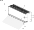
Fig. 10 is a diagram illustrating the flow direction of air discharged through the air conditioner in the arrangement of the vane as inFig. 7 . - The above and other objectives, features, and other advantages of the present disclosure will be more clearly understood from the following detailed description when taken conjointly with the accompanying drawings. The present disclosure may, however, be embodied in many different forms and should not be construed as being limited to only the embodiments set forth herein. These embodiments are provided solely to ensure that this disclosure is complete and will fully convey the scope of the invention to those skilled in the art. The present disclosure is defined solely by the claims. The same reference numerals are used throughout the drawings to designate the same or similar components.
- Hereinafter, air conditioners according to embodiments of the present disclosure will be described with reference to the accompanying drawings.
- Referring to
Fig. 1 , the configuration of an air conditioner according to the present disclosure will be described. - The air conditioner includes a
casing 10 that defines an external appearance thereof. Aninlet 12 is formed in a top of thecasing 10. Air from the upper side of thecasing 10 may be introduced into thecasing 10 through aninlet 12. Thecasing 10 defines a space where a fan 50 (seeFig. 4 ) and a heat exchanger 70 (seeFig. 4 ) are arranged. Thecasing 10 forms afirst outlet 36 in the front. The air conditioner may include adischarge cover 30 that is disposed on the front of thecasing 10 and forms thefirst outlet 36. The air conditioner may include afront vane 40 that is disposed on a side of thedischarge cover 30 and guides the direction of air discharged through thefirst outlet 36. - A
display 170 may be disposed on the front surface of thecasing 10. - A
suction grill 20 may be disposed on the upper side of thecasing 10. Thesuction grill 20 is detachably disposed on thecasing 10. - The
suction grill 20 may be disposed on the upper side of thecasing 10 where theinlet 12 is formed. Thesuction grill 20 may include a plurality ofribs 22 extending in a left-right direction or in a front-back direction. - A
mesh 24 may be disposed in thesuction grill 20 to filter out foreign substances in the air introduced into theinlet 12. Themesh 24 may be disposed between the plurality ofribs 22. - The structure of the air conditioner will be described with reference to
Fig. 2 . - The
display 170 may be disposed on the front surface of thecasing 10. Thedisplay 170 may display information such as the operating state of the air conditioner or the temperature of the indoor space. - The
suction grill 20 may have a shape that protrudes upward. Thus, when seeing thecasing 10 from the front, it may have a structure in which a side of thesuction grill 20 is exposed. - The
first outlet 36 is disposed on a lower portion of the front surface of thecasing 10. Thefront vane 40 is disposed in thefirst outlet 36. Thefront vane 40 is fixedly disposed on a side of thecasing 10. Therefore, thefront vane 40 may guide air flowing to thefirst outlet 36 in one direction. - The
discharge cover 30 may be disposed in thecasing 10 to form thefirst outlet 36. Thedischarge cover 30 may be disposed in thecasing 10 forming the front surface. Thedischarge cover 30 may have a structure disposed inside thecasing 10. Thedischarge cover 30 may form thefirst outlet 36 that is formed in the left-right direction. Thefront vane 40 may be disposed on thedischarge cover 30. - The lower configuration of the air conditioner will be described with reference to
Fig. 3 . - The air conditioner includes a
lower cover 46. Thelower cover 46 is disposed on the open lower side of thecasing 10. Asecond outlet 48 is formed between thelower cover 46 and thecasing 10. Afirst vane 120 is disposed between thelower cover 46 and thecasing 10 to open or close thesecond outlet 48. - The
second outlet 48 may be formed in front of thelower cover 46. - Depending on the arrangement of the vane, the
second outlet 48 may be opened or closed. - The entire configuration of the air conditioner will be schematically described with reference to
Fig. 4 . - The air conditioner of the present disclosure includes the
casing 10 that defines an external appearance. Thecasing 10 may have a structure covering the front surface and both sides thereof. Thecasing 10 may be open at the lower side thereof. - The
casing 10 may have a structure that is open at the upper side thereof. Thecasing 10 may form theinlet 12 on an upper surface thereof. Anupper rib 14 may be disposed on the upper surface of thecasing 10. Theupper rib 14 may maintain the arrangement of thesuction grill 20. - The
casing 10 may form thefirst outlet 36 in the front. The discharge cover 30 in which thefirst outlet 36 is formed may be disposed on the front of thecasing 10. Thedischarge cover 30 may also be formed integrally with thecasing 10. - The
casing 10 may have a shape that is open in a rear thereof. Thecasing 10 may define a space in which thefan 50 and theheat exchanger 70 are disposed. - The air conditioner of the present disclosure includes the
suction grill 20 that is disposed in theinlet 12 of thecasing 10. The plurality ofribs 22 are arranged in thesuction grill 20 to extend in the left-right direction or the front-back direction. Themesh 24 may be disposed between the plurality ofribs 22. - The
suction grill 20 may be disposed above theupper rib 14 that is formed in thecasing 10. - The air conditioner of the present disclosure includes the
discharge cover 30 that forms thefirst outlet 36. Thedischarge cover 30 is fixedly disposed on the front surface of thecasing 10. Thefirst outlet 36 is formed in thedischarge cover 30 to extend in the left-right direction. - A plurality of
front ribs 38 are disposed in thedischarge cover 30 to extend in a vertical direction and to be spaced apart from each other in the left-right direction. Thefront ribs 38 may be connected to thefront vane 40. Thefront ribs 38 may maintain the arrangement of thefront vane 40. - The air conditioner of the present disclosure includes the
front vane 40 that guides the direction of the air discharged through thefirst outlet 36. Thefront vane 40 may be fixedly disposed on thedischarge cover 30. Thefront vane 40 may be fixedly disposed in thecasing 10. - The
front vane 40 may have a structure connected to each of the plurality offront ribs 38 of thedischarge cover 30. Thefront vane 40 may direct the air flowing to thefirst outlet 36 in a direction horizontal to the ground or upward from the direction horizontal to the ground. - The air conditioner of the present disclosure includes the
lower cover 46 disposed on the lower surface of thecasing 10. Thelower cover 46 may be disposed to cover a portion of the open lower side of thecasing 10. Asecond outlet 48 may be formed in thelower cover 46. - The
lower cover 46 is detachably disposed on thecasing 10. Thelower cover 46 may be fixedly disposed in thecasing 10 or aninner body 80 that will be described below. Thelower cover 46 may be in the shape of a "U"-shaped plate. Thesecond outlet 48 may be formed between thecasing 10 and thelower cover 46. - The air conditioner of the present disclosure includes a
stabilizer 100. Thestabilizer 100 ma guide the flow of air discharged by thefan 50. Thestabilizer 100 may guide the upper side of the air flowing forward and downward with thefan 50. Thestabilizer 100 may support a side of theheat exchanger 70. - The
vanes stabilizer 100. Thevanes stabilizer 100. - A
vane motor 108 may be disposed on thestabilizer 100 to change the arrangement of thevanes - The air conditioner of the present disclosure includes the
first vane 120 that opens or closes thesecond outlet 48. Thevanes second outlet 48. Thevanes fan 50 to thefirst outlet 36. - The air conditioner of the present disclosure includes the
inner body 80 that is disposed in thecasing 10 and rotatably supports thefan 50. Thefan 50 may be disposed in theinner body 80. A fan motor 52 may be disposed in theinner body 80 to rotate thefan 50. - The
inner body 80 is fixedly disposed in thecasing 10. Theinner body 80 may guide the air flowing rearward or downward by thefan 50. Alouver 90 may be disposed in theinner body 80 to adjust the direction of the flowing air leftward or rightward. Thelouver 90 may guide the direction of the air flowing to thefirst outlet 36 or thesecond outlet 48 leftward or rightward. - The air conditioner of the present disclosure includes the
fan 50 that sends air from theinlet 12 to thefirst outlet 36 or thesecond outlet 48. Thefan 50 is rotatably disposed in thecasing 10. Thefan 50 may use a cross-flow fan that sucks in air on one side in a radial direction relative to a rotation axis and discharges the air on the other side in the radial direction. - The
fan 50 may suck air from theinlet 12 located on the upper side of thefan 50. Further, thefan 50 may discharge air to thefirst outlet 36 or thesecond outlet 48 located on the lower side of thefan 50. - The air conditioner of the present disclosure includes the fan motor 52 that rotates the
fan 50. The fan motor 52 is disposed on one side of theinner body 80. - The air conditioner of the present disclosure includes a
motor cover 54 that covers one side of the fan motor 52. Themotor cover 54 may be mounted on theinner body 80. Themotor cover 54 may be mounted on one side of theinner body 80 or acontrol box 60 that will be described below. - The air conditioner of the present disclosure includes the
heat exchanger 70 that exchanges heat with air flowing through the interior of thecasing 10. Theheat exchanger 70 may exchange heat between refrigerant and air. Theheat exchanger 70 may exchange heat with air discharged to the indoor space. Theheat exchanger 70 may exchange heat with air flowing through thefirst outlet 36 or thesecond outlet 48. - The
heat exchanger 70 may have at least one bent shape. Theheat exchanger 70 is disposed above thefan 50. Theheat exchanger 70 may perform heat exchange on the air flowing through thefan 50. - The air conditioner of the present disclosure includes the
control box 60 in which an electrical component for controlling the operation of the air conditioner is disposed. Thecontrol box 60 may be mounted on one side of theinner body 80. Thecontrol box 60 may be disposed on one side of the fan motor 52. The fan motor 52 may be disposed between thecontrol box 60 and thefan 50. - The air conditioner of the present disclosure includes the
display 170 that displays the temperature or the operating state. Thedisplay 170 may be disposed on one side of thecontrol box 60. Thedisplay 170 is disposed on the inside of thecasing 10. Thedisplay 170 is disposed on the rear of the front wall of thecasing 10. Thedisplay 170 may output a state to the front wall of thecasing 10. - The air conditioner of the present disclosure includes a
rear cover 190 positioned at the rear of thecasing 10. Therear cover 190 may mount the air conditioner on a wall. Therear cover 190 may be configured to be coupled to thecasing 10 or theinner body 80. - The air conditioner of the present disclosure includes a
heat exchanger holder 180 that is disposed on one side of theinner body 80 and holds the arrangement of theheat exchanger 70. Theheat exchanger holder 180 is fixedly disposed in theinner body 80. In an area where theheat exchanger holder 180 is coupled to theinner body 80, thefan 50 is rotatably disposed. - The
heat exchanger holder 180 is disposed to be coupled to theinner body 80 on the opposite side where the fan motor 52 is disposed. - The air conditioner of the present disclosure includes an upper cover 61 that covers the upper side of the
control box 60 or the fan motor 52. The upper cover 61 may cover the upper side of the fan motor 52 in an area that is open to the upper side of thecasing 10. - The arrangement of components revealed in the cross-section of the air conditioner will be described with reference to
Fig. 5 . - The
inlet 12 is formed in the upper side of thecasing 10. Theinlet 12 is formed above thefan 50. - The
heat exchanger 70 is disposed above thefan 50. Theheat exchanger 70 may have a structure that is bent in at least one area. Theheat exchanger 70 of the present disclosure may include sections bent in two areas. - The
heat exchanger 70 includes afirst heat exchanger 70a disposed in front of thefan 50, asecond heat exchanger 70b bent from thefirst heat exchanger 70a and extending upward and rearward, and athird heat exchanger 70c bent from thesecond heat exchanger 70b and extending downward and rearward. - One end of the
heat exchanger 70 is disposed on the upper side of thestabilizer 100. The other end of theheat exchanger 70 is disposed on the upper side of theinner body 80. - The
fan 50 is disposed between theinner body 80 and thestabilizer 100. Thefan 50 rotates to suck in air from the front and upper side. Thefan 50 rotates to discharge air to the rear and lower side. - The air moved by the
fan 50 may flow into adischarge path 18 defined by theinner body 80 and thestabilizer 100. - The
inner body 80 is positioned at the rear and lower side of thefan 50. - The
inner body 80 includes asupport body 82 that is positioned at the rear of thefan 50 and supports one side of theheat exchanger 70, and aguide body 84 that guides air moved by the rotation of thefan 50 toward the front and lower side. - The
guide body 84 includes aninlet guide body 85 that protrudes upward from thefan 50 and guides air introduced into thefan 50. Theguide body 84 includes afirst guide 86 that guides air moved by the rotation of thefan 50 toward the front and lower side. - The
first guide 86 may be disposed to become farther from thefan 50 toward the lower side. Thefirst guide 86 may include anupper guide 86a that is provided around thefan 50 and has a curved shape, and alower guide 86b that extends forward and downward from a lower end of theupper guide 86a. - The
louver 90 may be disposed on one side of thefirst guide 86 to control the direction of air, moved downward by the rotation of thefan 50, in the left-right direction. Thelouver 90 may have its position changed in the left-right direction through a separate louver motor (not shown). - A
sterilization lamp 92 may be disposed on one side of thefirst guide 86 to emit ultraviolet light in a direction in which thefan 50 is positioned. Thesterilization lamp 92 may be disposed on a side where thelouver 90 is disposed. - The
stabilizer 100 is positioned upwardly apart from thefirst guide 86 of theinner body 80. - The
stabilizer 100 includes asecond guide 102 that is positioned upwardly apart from thefirst guide 86, anend guide 104 that is bent from an upper end of thesecond guide 102 and extends upward, and a plurality ofupper protrusions 106 that are provided on the upper surface of thesecond guide 102, are spaced apart from each other in the front-back direction, and extend upward. - The
second guide 102 includes at least two walls having different inclined surfaces. Thedischarge path 18 may be formed between thesecond guide 102 and thefirst guide 86. - The
vanes stabilizer 100. Inside thecasing 10, thevanes second outlet 48. Thevanes first vane 120 that opens or closes thesecond outlet 48, and thesecond vane 130 that is disposed on thedischarge path 18. - The
first vane 120 and thesecond vane 130 may be connected by a plurality of links. The air conditioner may include adrive link 140 connected to thevane motor 108, afirst link 142 connecting thedrive link 140 and thefirst vane 120, and asecond link 144 connecting thedrive link 140 and thesecond vane 130. The air conditioner may include anauxiliary link 146 connecting thestabilizer 100 and thefirst vane 120. - The
first vane 120 may open or close thesecond outlet 48. Thesecond vane 130 may be disposed above thefirst vane 120. The length of thefirst vane 120 formed in the front-back direction may be longer than the length of thesecond vane 130 formed in the front-back direction. - A
net steel 160 may be disposed in thestabilizer 100. Thenet steel 160 may prevent a user or the like from approaching thefan 50 through the inside of thedischarge path 18. - The
second outlet 48 is positioned on the lower surface of thecasing 10. Thefirst outlet 36 is positioned on the front surface of thecasing 10. When the first vane is positioned to close thesecond outlet 48, thefirst vane 120 may guide air moved by thefan 50 to thefirst outlet 36. - The
discharge cover 30 may be disposed on one side of thecasing 10 that is open toward the front. Thefirst outlet 36 is formed in thedischarge cover 30. Thedischarge cover 30 includes a discharge-coverlower part 34 connected to the lower end of thecasing 10, and a discharge-coverupper part 32 positioned upwardly apart from the discharge-coverlower part 34. - The
front vane 40 is disposed on thedischarge cover 30 to guide air discharged through thefirst outlet 36. - The
casing 10 includes aborder wall 16 connected to the discharge-coverlower part 34 at the lower end of the front surface. - Hereinafter, with reference to
Fig. 6 , a configuration for allowing air discharged by thefan 50 to flow while thefirst vane 120 closes thesecond outlet 48 will be described in detail. - The
first guide 86 of theinner body 80 and thesecond guide 102 of thestabilizer 100 define thedischarge path 18. Thefirst guide 86 of theinner body 80, thesecond guide 102 of thestabilizer 100, and thefirst vane 120 may define thedischarge path 18. - The
discharge path 18 includes afirst discharge path 18a formed between thefirst guide 86 and thesecond guide 102, and asecond discharge path 18b formed between the firstinner vane 120 and thesecond guide 102. - The
second discharge path 18b may be formed in a state where the firstinner vane 120 closes thesecond outlet 48. - An inclination angle θ1 formed between the
first guide 86 and an imaginary horizontal line HL that is parallel to the ground may be formed to be greater than an inclination angle θ2 formed between thesecond guide 102 and the imaginary horizontal line HL. - That is, a width formed by the cross-section of the
discharge path 18 formed between thefirst guide 86 of theinner body 80 and thesecond guide 102 of thestabilizer 100 nay increase as it goes farther away from thefan 50. - The
second guide 102 includes arear guide 102a, amiddle guide 102b extending forward from therear guide 102a, and afront guide 102c extending forward from themiddle guide 102b. - The
rear guide 102a may be arranged to extend forward and downward as it goes farther away from thefan 50. Therear guide 102a may have a shape that is inclined forward and downward. - The
rear guide 102a may form thedischarge path 18 with thelower guide 86b of thefirst guide 86. The inclination angle θ2 formed between therear guide 102a and the imaginary horizontal line HL may be formed smaller than the inclination angle θ1 formed between thefirst guide 86 and the imaginary horizontal line HL. - A portion of the
rear guide 102a is disposed above thefirst guide 86. Another portion of therear guide 102a is disposed above thesecond outlet 48. Another portion of therear guide 102a is disposed above thefirst vane 120. - A length 102aL by which the
rear guide 102a extends in the front-back direction may be formed longer than a length 102bL by which themiddle guide 102b extends in the front-back direction. The length 102aL of therear guide 102a extending in the front-back direction may be formed shorter than a length 86bL of thelower guide 86b of thefirst guide 86 extending in the front-back direction. - The
middle guide 102b may be disposed approximately parallel to the ground. Themiddle guide 102b is disposed above thesecond outlet 48. Themiddle guide 102b may be disposed above thefirst vane 120. Themiddle guide 102b is disposed approximately parallel to thefirst vane 120 with thesecond outlet 48 closed. - The length 102bL of the
middle guide 102b extending in the front-back direction may be formed shorter than alength 120L of thefirst vane 120 extending in the front-back direction. The length 120aL of therear guide 102a extending in the front-back direction may be formed to be 1.5 to 3 times the length 102bL of themiddle guide 102b extending in the front-back direction. - An angle θ3 formed between the
middle guide 102b and therear guide 102a may be formed to be larger than an angle θ4 formed between thefirst guide 86 and thefirst vane 120 when thesecond outlet 48 is closed. - The length 102bL of the
middle guide 102b extending in the front-back direction may be formed longer than the length 102cL of thefront guide 102c extending in the front-back direction. The length 102bL of themiddle guide 102b extending in the front-back direction may be formed to be 2 to 4 times the length 102cL of thefront guide 102c extending in the front-back direction. - The
front guide 102c may extend forward and downward from themiddle guide 102b. Thefront guide 102c is connected to the discharge-coverupper part 32 of thedischarge cover 30. - The
front guide 102c is disposed above thesecond outlet 48. Thefront guide 102c is disposed above thefirst vane 120. - The
first guide 86 includes theupper guide 86a that is arranged around thefan 50 and has a bent shape. Theupper guide 86a may be formed so that a gap between the upper guide and thefan 50 increases as it goes downward. - The
upper guide 86a may be positioned above thesecond guide 102 in a vertical direction. Theupper guide 86a may guide air, discharged to the rear by the rotation of thefan 50, downward. - The
first guide 86 includes thelower guide 86b that guides air moved downward by the rotation of thefan 50 forward. Thelower guide 86b may have a structure extending forward and downward. - The
first guide 86 may guide air moved by the rotation of thefan 50 to thesecond outlet 48. Thelower guide 86b of thefirst guide 86 has a structure extending toward thesecond outlet 48. - The
first vane 120 may be disposed in a position that closes thesecond outlet 48. Thefirst vane 120 includes a vaneupper surface 121 that contacts air moved by the rotation of thefan 50. Thefirst vane 120 includes a vanelower surface 122 that is positioned in an opposite direction to the vaneupper surface 121. - Referring to the drawing, the vane
upper surface 121 and the vanelower surface 122 may be formed on different plates. However, unlike the drawing, the vaneupper surface 121 and the vanelower surface 122 may also be formed on a single plate. - The vane
upper surface 121 may be disposed approximately parallel to themiddle guide 102b of thesecond guide 102. The vaneupper surface 121 may contact air flowing along thedischarge path 18. The vaneupper surface 121 may guide air flowing along thedischarge path 18. - As shown in
Fig. 6 , when thefirst vane 120 closes thesecond outlet 48, air flowing through thedischarge path 18 may move along the vaneupper surface 121 of thefirst vane 120 and then flow to thefirst outlet 36. - As shown in
Fig. 6 , a state in which thefirst vane 120 closes thesecond outlet 48 may be set as a first position P1 of the vane. That is, the vane may be arranged so that thefirst vane 120 closes thesecond outlet 48 at the first position P1. - A plurality of
protrusions 121c protruding upward and spaced apart from each other in the front-back direction may be formed on the vaneupper surface 121 of thefirst vane 120. The plurality ofprotrusions 121c may prevent dew from forming on the upper side of thefirst vane 120. - A rear end 121b of the vane
upper surface 121 may form an inclined surface that extends downward as it goes rearward. Afront end 121a of the vaneupper surface 121 may form an inclined surface that extends downward as it goes forward. - The rear end 121b may be formed to have a front-back length 121bL that is 0.1 to 0.2 times the front-
back length 120L of thefirst vane 120. The front-back direction length 121aL of thefront end 121a may be formed to be 0.1 to 0.2 times the front-back direction length 120L of thefirst vane 120. - An insulation material may be disposed inside the
first vane 120. - The
second vane 130 may be disposed above thefirst vane 120. When thefirst vane 120 closes thesecond outlet 48, thesecond vane 130 may be disposed to send air forward. - At a first position P1 of the vane, the
second vane 130 sends air flowing forward and downward through thedischarge path 18 to thefirst outlet 36. At the first position P1 of the vane, thesecond vane 130 may be disposed in a downwardly convex shape. - At the first position P1 of the vane, the rear end 121b of the
second vane 130 may be positioned to face rearward and upward. At the first position P1 of the vane, thefront end 121a of thesecond vane 130 may be positioned to face forward or face forward and upward. - A
length 130L of thesecond vane 130 in the front-back direction may be equal to or less than half thelength 120L of thefirst vane 120 in the front-back direction. - The
discharge cover 30 is disposed at the front of thecasing 10. Thedischarge cover 30 may be disposed inside thecasing 10. Inside thedischarge cover 30, a first outlet path 30a (or 'third discharge path') may be formed to guide air flowing through thedischarge path 18 to thefirst outlet 36. - The first outlet path 30a may send air flowing through the
second discharge path 18b forward and upward. The first outlet path 30a may have a shape inclined forward and upward. - The first outlet path 30a may be formed between the discharge-cover
upper part 32 and the discharge-coverlower part 34. Thefirst outlet 36 may be formed at the front end of the first outlet path 30a. - The discharge-cover
lower part 34 may include aninclined guide wall 34a that forms a surface inclined forward and upward, and a vane-respondingwall 34b disposed to face thefirst vane 120. - The
inclined guide wall 34a causes air flowing along the vaneupper surface 121 of thefirst vane 120 to flow forward and upward. Theinclined guide wall 34a may guide air flowing along the vaneupper surface 121 of thefirst vane 120 to thefirst outlet 36. - The
inclined guide wall 34a is disposed under thefirst outlet 36. Theinclined guide wall 34a is disposed in front of thesecond outlet 48. Theinclined guide wall 34a has a structure that extends upward as it moves away from thesecond outlet 48. - The
inclined guide wall 34a may be disposed to be inclined upward from a surface formed by the vaneupper surface 121 of thefirst vane 120. That is, air flowing through thedischarge path 18 and flowing along the upper surface of thefirst vane 120 may be directed upward. This may discharge air, which is discharged through thefirst outlet 36, in the forward horizontal direction or upward from the forward horizontal direction. This may send air discharged forward through thefirst outlet 36 to a long distance. - The front end of the
inclined guide wall 34a may be connected to theborder wall 16 of thecasing 10. The front end of theinclined guide wall 34a connected to theborder wall 16 of thecasing 10 may be arranged approximately horizontally. - The air conditioner of the present disclosure may include the
inclined guide wall 34a that is disposed inside thecasing 10 and guides air flowing along thefirst vane 120 to thefirst outlet 36. Theinclined guide wall 34a may be a separate component placed inside thecasing 10. Theinclined guide wall 34a may be formed integrally with thecasing 10 and may be arranged in an internal space defined by thecasing 10. - The
inclined guide wall 34a may connect one side of the firstinner vane 120 with thesecond outlet 48 closed and the lower end of thefirst outlet 36. Theinclined guide wall 34a may be disposed in front of thesecond outlet 48 and under thefirst outlet 36. Theinclined guide wall 34a may have a shape inclined toward the front and upward. - The vane-responding
wall 34b is disposed to face thefront end 121a of thefirst vane 120 positioned at the first position P1. The vane-respondingwall 34b has a structure that extends downward as it moves farther forward from thesecond outlet 48. - The discharge-cover
upper part 32 may form a substantially horizontal surface. The discharge-coverupper part 32 may have a structure extending from thesecond guide 102. - The
front vane 40 is disposed between the discharge-coverlower part 34 and the discharge-coverupper part 32. Thefront vane 40 may extend in the front-back direction to guide the flow of air discharged through thefirst outlet 36. Thefront vane 40 may have a structure that extends upward as it goes forward. - An inclination angle θ5 formed between the
front vane 40 and the imaginary horizontal line HL may be formed smaller than an inclination angle θ6 formed between the discharge-coverlower part 34 and the imaginary horizontal line HL. In other words, the discharge-coverlower part 34 is arranged to be further inclined upward as it goes forward compared to thefront vane 40. - The inclination angle θ5 formed between the
front vane 40 and the imaginary horizontal line HL may be formed smaller than the inclination angle θ6 formed between theinclined guide wall 34a of the discharge-coverlower part 34 and the imaginary horizontal line HL. - The inclination angle θ5 formed between the
front vane 40 and the imaginary horizontal line HL may be formed larger than an inclination angle θ7 formed between the vaneupper surface 121 of thefirst vane 120 and the imaginary horizontal line HL. The inclination angle θ5 formed between thefront vane 40 and the imaginary horizontal line HL may be formed larger than an inclination angle θ8 formed between the discharge-coverupper part 32 and the imaginary horizontal line HL. - The first outlet path 30a may be formed so that a cross-sectional area of the path becomes smaller as it goes forward. The first outlet path 30a may be formed with a smaller vertical gap as it goes forward.
- The area of the
first outlet 36 may be formed smaller than that of thesecond outlet 48. Referring toFig. 6 , a gap 36h formed by thefirst outlet 36 in the vertical direction may be smaller than a gap 48w formed by thesecond outlet 48 in the front-back direction. - Air moved by the rotation of the
fan 50 flows forward and downward along thedischarge path 18. Further, air flowing between thefirst vane 120 and thesecond guide 102 may be discharged through the first outlet path 30a to thefirst outlet 36. Air discharged through the first outlet path 30a to thefirst outlet 36 may flow forward and upward. - Therefore, when the vane is in the first position P1, air may be discharged through the
first outlet 36. Referring toFig. 9 , air may be discharged through thefirst outlet 36 to the front of thecasing 10 by operating thefan 50. At this time, air discharged through thefirst outlet 36 may flow forward to a long distance. - Referring to
Fig. 7 , the arrangement of the vane and the flow of air in the second position P2 of the vane will be described. - The second position P2 of the vane may be in a state where the
second outlet 48 is open. Therefore, in the second position P2 of the vane, thefirst vane 120 may be disposed under thesecond outlet 48. In the second position P2 of the vane, thefirst vane 120 may be disposed under thesecond outlet 48 to be spaced apart therefrom. In the second position P2 of the vane, thefirst vane 120 may cause air flowing to thesecond outlet 48 to flow forward and downward or to flow downward. - Unlike the drawing, in the second position P2 of the vane, it is also possible for a portion of the
first vane 120 to be positioned above thesecond outlet 48. - When moving from the first position P1 of the vane to the second position P2 of the vane, the
second vane 130 may move downward. When moving from the first position P1 of the vane to the second position P2 of the vane, thesecond vane 130 may move obliquely downward. - In the second position P2 of the vane, the
first vane 120 may guide the direction of air flowing to thesecond outlet 48. In the second position P2 of the vane, air discharged through thesecond outlet 48 may flow forward and downward along thefirst vane 120. - In the second position P2 of the vane, both the
first outlet 36 and thesecond outlet 48 are opened. At this time, air flowing through thedischarge path 18 may mainly flow forward and downward to thesecond outlet 48 that is open downward. Some air may be discharged to thefirst outlet 36. However, most of the air is discharged through thesecond outlet 48 and may flow forward and downward or flow downward along thefirst vane 120 that is arranged to open thesecond outlet 48. - Referring to
Fig. 10 , when the vane is placed at the second position P2, air discharged through thesecond outlet 48 and/or thefirst outlet 36 may flow forward and downward. Since the main airflow of the discharged air is discharged through thesecond outlet 48, the air may be discharged forward and downward. - Referring to
Fig. 8 , the arrangement of the vane and the flow of air in a third position P3 of the vane will be described. - The third position P3 of the vane is in a state where the
second outlet 48 is open. Therefore, in the third position P3 of the vane, thefirst vane 120 may be disposed under thesecond outlet 48. In the third position P3 of the vane, the lower end of thefirst vane 120 is disposed under thesecond outlet 48. Further, in the third position P3 of the vane, the upper end of thefirst vane 120 is disposed above thesecond outlet 48. - In the third position P3 of the vane, the
first vane 120 may cause air flowing to thesecond outlet 48 to flow under thesecond outlet 48. - When moving from the second position P2 of the vane to the third position P3 of the vane, the rear end of the
first vane 120 may move upward. When moving from the second position P2 of the vane to the third position P3 of the vane, the front end of thefirst vane 120 may move downward. - When moving from the second position P2 of the vane to the third position P3 of the vane, the
first vane 120 may move while rotating counterclockwise. - In the third position P3 of the vane, the lower end of the
second vane 130 is disposed under thesecond outlet 48. In the third position P3 of the vane, the upper end of thesecond vane 130 is disposed above thesecond outlet 48. - When moving from the second position P2 of the vane to the third position P3 of the vane, the
second vane 130 may move downward to some extent. When moving from the second position P2 of the vane to the third position P3 of the vane, thesecond vane 130 may move downward while rotating counterclockwise. - In the third position P3 of the vane, the
first vane 120 may guide the direction of air flowing to thesecond outlet 48. In the third position P3 of the vane, air discharged through thesecond outlet 48 may flow under thesecond outlet 48 along thefirst vane 120. - In the third position P3 of the vane, both the
first vane 120 and thesecond vane 130 are arranged to be inclined downward. - In the third position P3 of the vane, both the
first outlet 36 and thesecond outlet 48 are opened. At this time, air flowing through thedischarge path 18 may mainly flow under thesecond outlet 48. - Some air may be discharged to the
first outlet 36. However, most of the air is discharged through thesecond outlet 48. Further, air may flow under thesecond outlet 48 by thefirst vane 120 and thesecond vane 130. - Although the present disclosure was provided above in relation to specific embodiments shown in the drawings, it is apparent to those skilled in the art that the present disclosure may be changed and modified in various ways without departing from the scope of the present disclosure, which is described in the following claims.
Claims (11)
- An air conditioner comprising:a casing (10) comprising an inlet (12), a first outlet (36) disposed at a front of the casing (10) and a second outlet (48) disposed at a lower surface of the casing (10) are formed;a fan (50) causing air to flow from the inlet (12) to the first outlet (36) or the second outlet (48); anda first vane (120) for opening or closing the second outlet (48), wherein the first vane (120) is configured to close the second outlet (48) to discharge air through the first outlet (36) or to open the second outlet (48) to discharge air under the first outlet (36).
- The air conditioner of claim 1, wherein the first vane (120) is configured to guide air moved by the fan (50) to the first outlet (36) when placed in the second outlet (48).
- The air conditioner of claim 1 or 2, wherein:the first outlet (36) is disposed in front of a rotation center of the fan (50), andthe second outlet (48) is disposed between the first outlet (36) and the rotation center of the fan (50) in a front-back direction.
- The air conditioner of any one of the preceding claims, further comprising:a first guide (86) disposed in the casing (10) and extending to the second outlet (48) under the fan (50);a second guide (102) disposed upwardly apart from the first guide (86),wherein a discharge path (18) is formed between the second guide (102) and the first guide (86).
- The air conditioner of any one of the preceding claims, further comprising a front guide (102c) partitioning the first outlet (36) and the second outlet (48).
- The air conditioner of claim 5, wherein an upper surface of the front guide (102c) extends in forward and upward directions where the first outlet (36) is disposed.
- The air conditioner of claim 4, 5 or 6, wherein the first guide (86) comprises:an upper guide (86a) forming a surface inclined forward and upward, anda lower guide (86b) forming a surface inclined forward and downward.
- The air conditioner of claim 7, wherein:a front end of the first vane (120) forms an inclined surface that extends downward as it goes forward, andthe front end of the first vane (120) is disposed under the lower guide (86b), when the first vane (120) closes the second outlet (48).
- The air conditioner of any one of the preceding claims, wherein a front vane (40) is disposed in the first outlet (36), preferably the front vane (120) is configured to be disposed to be inclined forward and upwardly
- The air conditioner of any one of the preceding claims, further comprising a second vane (130) guiding a flow generated by the fan (50).
- The air conditioner of claim 10, wherein, when the first vane (120) is disposed in the second outlet (48), the second vane (130) is disposed so that a front end of the second moving vane (130) faces a front to guide air to the first outlet (36).
Applications Claiming Priority (1)
| Application Number | Priority Date | Filing Date | Title |
|---|---|---|---|
| KR1020230170003A KR20250081552A (en) | 2023-11-29 | 2023-11-29 | Air Conditioner |
Publications (1)
| Publication Number | Publication Date |
|---|---|
| EP4563903A1 true EP4563903A1 (en) | 2025-06-04 |
Family
ID=93741502
Family Applications (1)
| Application Number | Title | Priority Date | Filing Date |
|---|---|---|---|
| EP24216236.0A Pending EP4563903A1 (en) | 2023-11-29 | 2024-11-28 | Air conditioner |
Country Status (6)
| Country | Link |
|---|---|
| US (1) | US20250172317A1 (en) |
| EP (1) | EP4563903A1 (en) |
| JP (1) | JP2025087664A (en) |
| KR (3) | KR20250081552A (en) |
| CN (1) | CN120062683A (en) |
| WO (1) | WO2025116435A1 (en) |
Families Citing this family (6)
| Publication number | Priority date | Publication date | Assignee | Title |
|---|---|---|---|---|
| USD1114967S1 (en) * | 2023-08-25 | 2026-02-24 | Lg Electronics Inc. | Wall-mounted air conditioner |
| USD1114968S1 (en) * | 2023-08-25 | 2026-02-24 | Lg Electronics Inc. | Wall-mounted air conditioner |
| USD1114966S1 (en) * | 2023-08-25 | 2026-02-24 | Lg Electronics Inc. | Wall-mounted air conditioner |
| USD1114964S1 (en) * | 2023-08-25 | 2026-02-24 | Lg Electronics Inc. | Wall-mounted air conditioner |
| USD1114963S1 (en) * | 2023-08-25 | 2026-02-24 | Lg Electronics Inc. | Wall-mounted air conditioner |
| USD1114965S1 (en) * | 2023-08-25 | 2026-02-24 | Lg Electronics Inc. | Wall-mounted air conditioner |
Citations (4)
| Publication number | Priority date | Publication date | Assignee | Title |
|---|---|---|---|---|
| KR20200095936A (en) | 2019-02-01 | 2020-08-11 | 엘지전자 주식회사 | Indoor unit for air conditioner and a method controlling the same |
| WO2023005329A1 (en) * | 2021-07-28 | 2023-02-02 | 青岛海尔空调器有限总公司 | Wall-mounted air conditioner indoor unit |
| WO2023082631A1 (en) * | 2021-11-15 | 2023-05-19 | 青岛海尔空调器有限总公司 | Wall-mounted air conditioner indoor unit |
| CN116635676A (en) * | 2020-11-13 | 2023-08-22 | Lg电子株式会社 | air conditioner |
Family Cites Families (5)
| Publication number | Priority date | Publication date | Assignee | Title |
|---|---|---|---|---|
| JPH0814408B2 (en) * | 1987-06-30 | 1996-02-14 | 株式会社東芝 | Louver mechanism of air conditioner |
| JP2545590Y2 (en) * | 1991-10-09 | 1997-08-25 | 松下冷機株式会社 | Air conditioner wind direction deflector |
| JPH07139797A (en) * | 1993-11-19 | 1995-05-30 | Fujitsu General Ltd | Air conditioner |
| JP4209912B2 (en) * | 2006-12-07 | 2009-01-14 | ダイキン工業株式会社 | Air conditioner |
| JP2021076283A (en) * | 2019-11-07 | 2021-05-20 | 三菱電機株式会社 | Indoor machine of air conditioner |
-
2023
- 2023-11-29 KR KR1020230170003A patent/KR20250081552A/en active Pending
-
2024
- 2024-11-22 WO PCT/KR2024/018650 patent/WO2025116435A1/en active Pending
- 2024-11-27 US US18/962,080 patent/US20250172317A1/en active Pending
- 2024-11-28 EP EP24216236.0A patent/EP4563903A1/en active Pending
- 2024-11-29 JP JP2024208285A patent/JP2025087664A/en active Pending
- 2024-11-29 CN CN202411735128.2A patent/CN120062683A/en active Pending
-
2025
- 2025-02-13 KR KR1020250018934A patent/KR20250081827A/en active Pending
- 2025-02-13 KR KR1020250018935A patent/KR20250081828A/en active Pending
Patent Citations (4)
| Publication number | Priority date | Publication date | Assignee | Title |
|---|---|---|---|---|
| KR20200095936A (en) | 2019-02-01 | 2020-08-11 | 엘지전자 주식회사 | Indoor unit for air conditioner and a method controlling the same |
| CN116635676A (en) * | 2020-11-13 | 2023-08-22 | Lg电子株式会社 | air conditioner |
| WO2023005329A1 (en) * | 2021-07-28 | 2023-02-02 | 青岛海尔空调器有限总公司 | Wall-mounted air conditioner indoor unit |
| WO2023082631A1 (en) * | 2021-11-15 | 2023-05-19 | 青岛海尔空调器有限总公司 | Wall-mounted air conditioner indoor unit |
Also Published As
| Publication number | Publication date |
|---|---|
| CN120062683A (en) | 2025-05-30 |
| WO2025116435A1 (en) | 2025-06-05 |
| US20250172317A1 (en) | 2025-05-29 |
| KR20250081552A (en) | 2025-06-05 |
| JP2025087664A (en) | 2025-06-10 |
| KR20250081827A (en) | 2025-06-05 |
| KR20250081828A (en) | 2025-06-05 |
Similar Documents
| Publication | Publication Date | Title |
|---|---|---|
| EP4563903A1 (en) | Air conditioner | |
| EP3690328B1 (en) | Indoor unit for air conditioner | |
| CN109764408B (en) | Air conditioner | |
| KR20190053594A (en) | Indoor unit of air conditioner | |
| WO2005052463A1 (en) | Air conditioner | |
| KR101611327B1 (en) | Stand type air conditioner | |
| KR20190051677A (en) | Indoor unit of air conditioner | |
| CN101298927B (en) | Air conditioner | |
| JP6507654B2 (en) | Air conditioner | |
| KR20220167149A (en) | Air conditioner | |
| KR100699257B1 (en) | microwave | |
| KR102940945B1 (en) | Air Conditioner | |
| KR20190051676A (en) | Indoor unit of air conditioner | |
| KR102938376B1 (en) | Air Conditioner | |
| KR20220104557A (en) | Air-conditioner | |
| JPH08270974A (en) | Air conditioner | |
| KR102666142B1 (en) | Air conditioner | |
| CN212870001U (en) | An air conditioner shell structure and wall-mounted machine | |
| JP2012042181A (en) | Indoor unit of air conditioner | |
| KR100437395B1 (en) | Indoor unit for airconditioner | |
| KR102104436B1 (en) | Air conditioner | |
| KR100420367B1 (en) | Indoor unit for airconditioner | |
| KR20260056532A (en) | Air Conditioner | |
| JP2022174354A (en) | Indoor unit of air conditioner | |
| KR20260056533A (en) | Air conditioner |
Legal Events
| Date | Code | Title | Description |
|---|---|---|---|
| PUAI | Public reference made under article 153(3) epc to a published international application that has entered the european phase |
Free format text: ORIGINAL CODE: 0009012 |
|
| STAA | Information on the status of an ep patent application or granted ep patent |
Free format text: STATUS: REQUEST FOR EXAMINATION WAS MADE |
|
| 17P | Request for examination filed |
Effective date: 20241128 |
|
| AK | Designated contracting states |
Kind code of ref document: A1 Designated state(s): AL AT BE BG CH CY CZ DE DK EE ES FI FR GB GR HR HU IE IS IT LI LT LU LV MC ME MK MT NL NO PL PT RO RS SE SI SK SM TR |