EP4563826A1 - Impeller, blower, and air conditioner - Google Patents
Impeller, blower, and air conditioner Download PDFInfo
- Publication number
- EP4563826A1 EP4563826A1 EP23860531.5A EP23860531A EP4563826A1 EP 4563826 A1 EP4563826 A1 EP 4563826A1 EP 23860531 A EP23860531 A EP 23860531A EP 4563826 A1 EP4563826 A1 EP 4563826A1
- Authority
- EP
- European Patent Office
- Prior art keywords
- blade
- blade thickness
- impeller
- thickness change
- center plate
- Prior art date
- Legal status (The legal status is an assumption and is not a legal conclusion. Google has not performed a legal analysis and makes no representation as to the accuracy of the status listed.)
- Pending
Links
Images





Classifications
-
- F—MECHANICAL ENGINEERING; LIGHTING; HEATING; WEAPONS; BLASTING
- F04—POSITIVE - DISPLACEMENT MACHINES FOR LIQUIDS; PUMPS FOR LIQUIDS OR ELASTIC FLUIDS
- F04D—NON-POSITIVE-DISPLACEMENT PUMPS
- F04D25/00—Pumping installations or systems
- F04D25/16—Combinations of two or more pumps ; Producing two or more separate gas flows
- F04D25/166—Combinations of two or more pumps ; Producing two or more separate gas flows using fans
-
- F—MECHANICAL ENGINEERING; LIGHTING; HEATING; WEAPONS; BLASTING
- F04—POSITIVE - DISPLACEMENT MACHINES FOR LIQUIDS; PUMPS FOR LIQUIDS OR ELASTIC FLUIDS
- F04D—NON-POSITIVE-DISPLACEMENT PUMPS
- F04D29/00—Details, component parts, or accessories
- F04D29/26—Rotors specially for elastic fluids
- F04D29/28—Rotors specially for elastic fluids for centrifugal or helico-centrifugal pumps for radial-flow or helico-centrifugal pumps
- F04D29/281—Rotors specially for elastic fluids for centrifugal or helico-centrifugal pumps for radial-flow or helico-centrifugal pumps for fans or blowers
- F04D29/282—Rotors specially for elastic fluids for centrifugal or helico-centrifugal pumps for radial-flow or helico-centrifugal pumps for fans or blowers the leading edge of each vane being substantially parallel to the rotation axis
-
- F—MECHANICAL ENGINEERING; LIGHTING; HEATING; WEAPONS; BLASTING
- F04—POSITIVE - DISPLACEMENT MACHINES FOR LIQUIDS; PUMPS FOR LIQUIDS OR ELASTIC FLUIDS
- F04D—NON-POSITIVE-DISPLACEMENT PUMPS
- F04D29/00—Details, component parts, or accessories
- F04D29/26—Rotors specially for elastic fluids
- F04D29/28—Rotors specially for elastic fluids for centrifugal or helico-centrifugal pumps for radial-flow or helico-centrifugal pumps
- F04D29/30—Vanes
-
- F—MECHANICAL ENGINEERING; LIGHTING; HEATING; WEAPONS; BLASTING
- F04—POSITIVE - DISPLACEMENT MACHINES FOR LIQUIDS; PUMPS FOR LIQUIDS OR ELASTIC FLUIDS
- F04D—NON-POSITIVE-DISPLACEMENT PUMPS
- F04D29/00—Details, component parts, or accessories
- F04D29/40—Casings; Connections of working fluid
- F04D29/42—Casings; Connections of working fluid for radial or helico-centrifugal pumps
- F04D29/4206—Casings; Connections of working fluid for radial or helico-centrifugal pumps especially adapted for elastic fluid pumps
- F04D29/4226—Fan casings
- F04D29/424—Double entry casings
-
- F—MECHANICAL ENGINEERING; LIGHTING; HEATING; WEAPONS; BLASTING
- F05—INDEXING SCHEMES RELATING TO ENGINES OR PUMPS IN VARIOUS SUBCLASSES OF CLASSES F01-F04
- F05D—INDEXING SCHEME FOR ASPECTS RELATING TO NON-POSITIVE-DISPLACEMENT MACHINES OR ENGINES, GAS-TURBINES OR JET-PROPULSION PLANTS
- F05D2240/00—Components
- F05D2240/20—Rotors
- F05D2240/30—Characteristics of rotor blades, i.e. of any element transforming dynamic fluid energy to or from rotational energy and being attached to a rotor
- F05D2240/305—Characteristics of rotor blades, i.e. of any element transforming dynamic fluid energy to or from rotational energy and being attached to a rotor related to the pressure side of a rotor blade
Definitions
- the present disclosure relates to an impeller, a blower, and an air conditioner.
- air flow may be separated from a blade surface due to a difference in an angle of a flow between the shroud ring side and the center plate side of the blade.
- a discharge air volume is biased to the center plate side, noise is generated, or the blowing efficiency is lowered.
- PTL 1 discloses a configuration made such that an outlet angle is different between a center plate side and a shroud ring side of a blade in order to prevent flow separation.
- the present disclosure has been made in view of such circumstances, and an object of the present disclosure is to provide an impeller, a blower, and an air conditioner in which it is possible to suppress a decrease in blowing efficiency or suppress a decrease in heat exchange performance.
- the impeller, the blower, and the air conditioner according to the present disclosure adopt the following means.
- an impeller having a rotation center on an axis, including: an annular shroud ring that forms an air suction port and is centered on the axis; a disk-shaped center plate that is provided to face the shroud ring and is centered on the axis; and a plurality of blades, each of which has a blade width along a direction of the axis between the shroud ring and the center plate, and which are disposed around the axis at predetermined intervals, in which a blade surface of each of the blades has, in a blade width direction, a blade thickness change surface, a center plate-side surface connected to a center plate side of the blade thickness change surface, and a shroud ring-side surface connected to a shroud ring side of the blade thickness change surface, and in the blade thickness change surface, an angle of the blade surface with respect to the axis in the blade width direction changes with respect to angles of the center plate-side surface and the
- a blower includes the impeller described above and a drive unit that rotates the impeller around the axis.
- an air conditioner includes the blower described above and a heat exchanger.
- a blower 20 is a sirocco fan that sends out air by rotating an impeller 30, and is mounted on, for example, an air conditioner indoor unit of ceiling duct type 1.
- the air conditioner 1 includes a housing 11, a heat exchanger 13, and the blower 20.
- the housing 11 is, for example, an outer box configured in a rectangular parallelepiped shape, and the heat exchanger 13 and the blower 20 are accommodated and installed in an internal space thereof.
- An air outlet 12 is open on a front surface of the housing 11, and is configured to blow out air that has been sent from the blower 20 and passed through the heat exchanger 13.
- the heat exchanger 13 is a device that performs heat exchange between a refrigerant and air, and extends along a longitudinal direction of the housing 11.
- the heat exchanger 13 is disposed on the air outlet 12 side (a front surface side of the housing 11) inside the housing 11.
- the blower 20 is a device that sends out air by rotating the impeller 30, as described above.
- the blower 20 is disposed on a back surface side of the heat exchanger 13 inside the housing 11. By disposing the blower 20 in this way, the air sent out from the blower 20 passes through the heat exchanger 13.
- a plurality of blowers 20 may be installed along the longitudinal direction of the heat exchanger 13, and in the case of Fig. 3 , three blowers 20 are installed.
- the blower 20 includes the impeller 30, a volute casing 21, an electric motor 22, and a drive shaft 23.
- the impeller 30 is a component having a substantially tubular outer shape centered on an axis X, in which a plurality of blades 40 are disposed at intervals around the axis X.
- the volute casing 21 is a container having a known scroll shape and accommodating the impeller 30.
- a bell mouth 21a and a discharge port 21b are formed in the volute casing 21. Air outside the volute casing 21 is taken into through the bell mouth 21a while being rectified by the rotating impeller 30. In addition, the air discharged from the rotating impeller 30 is rectified and pressurized inside the volute casing 21 and is sent out from the discharge port 21b.
- the electric motor 22 is a device for rotating the impeller 30 around the axis X via the drive shaft 23.
- the drive shaft 23 is connected to a center plate 31 of the impeller 30, which will be described later. Accordingly, the driving force (rotation) of the drive shaft 23 connected to the electric motor 22 is transmitted to the impeller 30.
- the electric motor 22 does not need to correspond to the impeller 30 on a one-to-one basis, and two impellers 30 may be rotated by one electric motor 22.
- the impellers 30 are disposed on both sides of the electric motor 22.
- three or more impellers 30 may be rotated by one electric motor 22.
- the impeller 30 includes the center plate 31, a shroud ring 32, and a plurality of blades 40, and has a substantially tubular outer shape centered on the axis X.
- the impeller 30 rotates in a direction of an arrow R shown in, for example, Fig. 5 or Fig. 6 with the axis X as a rotation center.
- the impeller 30 is made of resin or metal, and may be integrally molded by, for example, injection molding, or may be configured by assembling a plurality of components.
- the impeller 30 shown in Fig. 5 is of a type including two shroud rings 32 on both sides of the center plate 31.
- the impeller 30 according to the present invention is not limited to this type and may be, for example, a type including one shroud ring 32.
- the center plate 31 is a disk-shaped portion centered on the axis X.
- the drive shaft 23 connected to the electric motor 22 is connected to the center of the center plate 31.
- the axis X coincides with a rotational axis of the drive shaft 23.
- the shroud ring 32 is an annular portion centered on the axis X.
- the shroud ring 32 is disposed to be spaced from the center plate 31 in the direction of the axis X and to face the center plate 31 in parallel.
- the shroud ring 32 is disposed to face the bell mouth 21a, and the air taken into the inside of the volute casing 21 from the bell mouth 21a flows into an inner region (a region surrounded by the blades 40) of the impeller 30 from a suction port 33 (an inner region of the shroud ring 32). That is, the shroud ring 32 defines the suction port 33 for air in the impeller 30.
- the blade 40 is disposed in parallel with the axis X between an outer peripheral edge of the center plate 31 and the shroud ring 32, and a blade width direction WD is along the direction of the axis X.
- a blade end on the center plate 31 side in the blade width direction WD is referred to as a base end 41
- a blade end on the shroud ring 32 side in the blade width direction WD is referred to as a tip 42.
- the blades 40 are disposed at predetermined intervals (gaps G) around the axis X.
- the gap G is an opening for discharging the air that has flowed into the inside of the impeller 30 (the inside region surrounded by all the blades 40) to the outside of the impeller 30.
- the blade 40 has a pressure surface 43 and a suction surface 44 as blade surfaces, and the cross-sectional shape thereof is a streamline shape.
- cross section means a cross section in a plane orthogonal to the axis X.
- the pressure surface 43 is a blade surface that is located at the front with respect to a rotation direction of the impeller 30.
- suction surface 44 is a blade surface that is located at the back with respect to the rotation direction of the impeller 30.
- the suction surface 44 is, for example, a smooth surface continuous in the blade width direction WD, and is substantially parallel to the axis X in the blade width direction WD.
- the pressure surface 43 has, for example, a base end-side surface 43a (a center plate-side surface), a blade thickness change surface 43b, and a tip-side surface 43c (a shroud ring-side surface), and these surfaces are connected to each other to form one pressure surface 43.
- the base end-side surface 43a is a surface located in a region on the base end 41 side of the blade 40 (a region closer to the base end 41 with respect to the blade thickness change surface 43b in the blade 40), one end of which is connected to the center plate 31, and the other end of which is connected to an edge of the blade thickness change surface 43b.
- the base end-side surface 43a is, for example, a surface substantially parallel to the axis X in the blade width direction WD. Therefore, the portion (range) of the blade 40 corresponding to the base end-side surface 43a has a substantially constant blade thickness in the blade width direction WD.
- the blade thickness change surface 43b is a surface located in a substantially central region of the blade 40, one end of which is connected to an edge of the base end-side surface 43a, and the other end of which is connected to an edge of the tip-side surface 43c.
- the blade thickness change surface 43b is a surface that changes a blade thickness of the blade 40 in the blade width direction WD from the center plate 31 toward the shroud ring 32. Details of the blade thickness change surface 43b will be described later.
- the tip-side surface 43c is a surface located in a region on the tip 42 side of the blade 40 (a region closer to the tip 42 with respect to the blade thickness change surface 43b in the blade 400), one end of which is connected to an edge of the blade thickness change surface 43b, and an outer edge of the other end of which is connected to the shroud ring 32.
- the tip-side surface 43c is, for example, a surface substantially parallel to the axis X in the blade width direction WD. Therefore, the portion (range) of the blade 40 corresponding to the tip-side surface 43c has a substantially constant blade thickness in the blade width direction WD. However, the blade thickness is thinner than the blade thickness of the portion of the blade 40 corresponding to the base end-side surface 43a.
- the blade thickness change surface 43b is a surface in which an angle with respect to the axis X in the blade width direction WD changes with respect to angles of the base end-side surface 43a and the tip-side surface 43c (an angle with respect to the axis X in the blade width direction WD).
- the blade thickness change surface 43b is not a surface substantially parallel to the axis X in the blade width direction WD, but is a surface inclined with respect to the axis X in the blade width direction WD.
- the blade thickness of the blade 40 changes in the blade width direction WD from the center plate 31 toward the shroud ring 32. Specifically, the blade thickness of the portion of the blade 40 corresponding to the tip-side surface 43c is thinner than the blade thickness of the portion of the blade 40 corresponding to the base end-side surface 43a. That is, when the blade 40 is viewed from the direction of the axis X, the cross-sectional shape of the portion of the blade 40 corresponding to the tip-side surface 43c falls within the range of the cross-sectional shape of the portion of the blade 40 corresponding to the base end-side surface 43a.
- blade thickness means, for example, a maximum blade thickness or a blade thickness in the same longitudinal cross section.
- the blade thickness of the portion of the blade 40 corresponding to the tip-side surface 43c is set to a blade thickness in a range of about 50% to 70% of the blade thickness of the portion of the blade 40 corresponding to the base end-side surface 43a.
- the tip-side surface 43c is offset to the suction surface 44 side along a normal direction with respect to the base end-side surface 43a, and the offset amount is in a range of 30% to 50% of the maximum blade thickness.
- the tip-side surface 43c is uniformly offset by 2 mm.
- the blade thickness of the portion of the blade 40 corresponding to the tip-side surface 43c is thinner than the blade thickness of the portion of the blade 40 corresponding to the base end-side surface 43a, when the gap G between the blades 40 adjacent to each other is viewed, the gap G in the region corresponding to the tip-side surface 43c is larger than the gap G in the region corresponding to the base end-side surface 43a.
- the blade thickness change surface 43b may be a surface perpendicular to the axis X, as shown in Fig. 9 , and may be a surface inclined with respect to the axis X, as shown in Fig. 11 .
- a gradient is generated on the pressure surface 43 due to the blade thickness change surface 43b.
- An angle ⁇ of the gradient is preferably, for example, 45 degrees or larger and 90 degrees or smaller with respect to the axis X.
- the blade thickness change surface 43b is a surface perpendicular to the axis X (refer to Fig. 9 ).
- the blade thickness change surface 43b is a protrusion portion/hooking portion of the pressure surface 43 in the blade width direction WD from the shroud ring 32 toward the center plate 31.
- the air taken into the inside of the volute casing 21 flows into an inner region (a region surrounded by the blades 40) of the impeller 30 along the direction of the axis X from the suction port 33 of the impeller 30.
- the air discharged from the gap G is rectified and pressurized in the inside of the volute casing 21 and is sent out from the discharge port 21b.
- the blade 40 of the impeller 30 according to the present embodiment is provided with the blade thickness change surface 43b, the following flow is formed when the air is discharged from each gap G.
- the air flowing from the shroud ring 32 toward the center plate 31 on the pressure surface 43 collides with the blade thickness change surface 43b.
- the direction of the flow of the air is turned to the outer side in the radial direction (a radial direction with respect to the axis X). Therefore, the air is actively discharged to the outside of the impeller 30 from the gap G in a region in the vicinity of the blade thickness change surface 43b.
- the air is actively discharged from the gap G in the region corresponding to the tip-side surface 43c to the outside of the impeller 30.
- the gap G in the region corresponding to the base end-side surface 43a is smaller than the gap G in the region corresponding to the tip-side surface 43c. Therefore, compared to the gap G corresponding to the tip-side surface 43c, the air is less likely to be discharged from the gap G corresponding to the base end-side surface 43a due to the influence of the flow path resistance.
- the blade thickness change surface 43b is provided in a range of 25% or more and 75% or less, and preferably in a range of 25% or more and 60% or less.
- the blade thickness change surface 43b may be provided at a plurality of locations on the pressure surface 43 along the blade width direction WD.
- the intermediate surface 43d corresponds to a center plate-side surface
- the tip-side surface 43c corresponds to a shroud ring-side surface
- the intermediate surface 43d corresponds to a shroud ring-side surface
- the base end-side surface 43a corresponds to a center plate-side surface.
- At least one of the plurality of blade thickness change surfaces 43b may be provided in a range of 25% or more and 75% or less, and preferably in a range of 25% or more and 60% or less.
- the blade thickness change surface 43b may be inclined from the shroud ring 32 side toward the center plate 31 side over a range from a leading edge 46 to a trailing edge 45 of the blade 40.
- a two-dot chain line shown in Fig. 15 indicates a blade thickness change surface 43b in a normal state where the inclination is not given (shown for reference).
- the gap G in the region corresponding to the tip-side surface 43c is larger than the gap G in the region corresponding to the base end-side surface 43a, the air is actively discharged from the gap G in the region corresponding to the tip-side surface 43c to the outside of the impeller 30.
- the air is less likely to be discharged from the gap G corresponding to the base end-side surface 43a due to the influence of the flow path resistance. Accordingly, it is possible to suppress the phenomenon in which the region in which the air is discharged is biased toward the center plate 31 side.
- the bias of the flow velocity in the inside of the volute casing 21 accommodating the impeller 30 is improved, and for example, the static pressure efficiency can be improved by suppressing a blowing loss occurring due to the generation of a swirling flow caused by the bias of the wind speed, or a decrease in heat exchange performance can be suppressed by making the wind speed distribution of the air blown from the volute casing 21 toward the heat exchanger 13 uniform.
- the blade thickness on the shroud ring 32 side is thinner than that on the center plate 31 side, when the blade 40 is injection-molded, it is possible to easily perform mold releasing in the direction of the axis X by using a mold having a simple shape. Therefore, the manufacturing cost of the impeller 30 can be reduced.
- the blade thickness change surface 43b is a surface perpendicular to the axis X, so that the direction of the flow of air can be rapidly turned.
- the suction surface 44 is a smooth surface continuous in the blade width direction WD, so that a draft angle required for mold releasing during injection molding can be provided on the suction surface 44 side.
- the blade thickness change surface 43b is located in a range of 25% or more and 60% or less, so that a region where air is easily discharged can be brought closer to the shroud ring 32 side.
- the blade thickness change surface 43b is provided at a plurality of locations on the pressure surface 43 along the blade width direction WD, so that, for example, even with respect to the impeller 30 having a large blade width with respect to the diameter of the impeller 30, the same effect can be obtained.
- the blade thickness change surface 43b is inclined from the shroud ring 32 side toward the center plate 31 side over a range from the leading edge 46 to the trailing edge 45 of the blade 40, so that the direction of the flow of the air flowing in from the suction port 33 can be smoothly turned. Therefore, it is possible to reduce a loss when the direction is turned, and it is possible to further improve the static pressure efficiency.
- the area (the area in contact with air) of the blade thickness change surface 43b is increased by an amount corresponding to the inclination, and the direction of the flow of air can be efficiently changed.
- the input of the electric motor 22 can be reduced due to the impeller 30 in which the static pressure efficiency is improved.
- the suction surface 44 may be provided with the same configuration as the blade thickness change surface 43b.
- a blade outlet angle of the portion of the blade 40 corresponding to the tip-side surface 43c and a blade outlet angle of the portion of the blade 40 corresponding to the base end-side surface 43a may be different from each other in a range in which the cross-sectional shape of the portion of the blade 40 corresponding to the tip-side surface 43c fits into the cross-sectional shape of the portion of the blade 40 corresponding to the base end-side surface 43a.
- An impeller (30) is an impeller having a rotation center on an axis (X), including: an annular shroud ring (32) that forms an air suction port (33) and is centered on the axis; a disk-shaped center plate (31) that is provided to face the shroud ring and is centered on the axis; and a plurality of blades (40), each of which has a blade width along a direction of the axis between the shroud ring and the center plate, and which are disposed around the axis at predetermined intervals, in which a blade surface (43) of each of the blades has, in a blade width direction (WD), a blade thickness change surface (43b), a base end-side surface (43a) connected to the center plate side of the blade thickness change surface, and a tip-side surface (43c) connected to the shroud ring side of the blade thickness change surface, and in the blade thickness change surface, an angle of the blade surface with respect to the axis (X), including: an annular
- the blade surface has, in the blade width direction, the blade thickness change surface, the base end-side surface connected to the center plate side of the blade thickness change surface, and the tip-side surface connected to the shroud ring side of the blade thickness change surface, and in the blade thickness change surface, the angle of the blade surface with respect to the axis in the blade width direction changes with respect to the angles of the base end-side surface and the tip-side surface such that the blade thickness on the center plate side with respect to the blade thickness change surface is thicker than the blade thickness on the shroud ring side with respect to the blade thickness change surface.
- part of the air that flows in from a suction port formed in the shroud ring collides with the blade thickness change surface along the direction of the axis, so that the direction of the flow is turned to the outer side in the radial direction. Therefore, part of the air can be discharged to the outer side in the radial direction in the region corresponding to the tip-side surface of the blade. Accordingly, it is possible to suppress the phenomenon in which the region in which the air is discharged is biased toward the center plate side.
- the gap (G) between the blades adjacent to each other is large on the shroud ring side, so that air flows easily, whereas the gap on the center plate side is small, so that air is difficult to flow due to the flow path resistance. Accordingly, it is possible to suppress the phenomenon in which the region in which the air is discharged is biased toward the center plate side.
- the bias of the flow velocity in the inside of the casing (21) accommodating the impeller is improved, and for example, the static pressure efficiency can be improved by suppressing a blowing loss occurring due to the generation of a swirling flow caused by the bias of the wind speed, or a decrease in heat exchange performance can be suppressed by making the wind speed distribution of the air blown from the casing toward the heat exchanger (13) uniform.
- the blade thickness on the shroud ring side is thinner than that on the center plate side, when the blade is injection-molded, it is possible to easily perform mold releasing in the direction of the axis by using a mold having a simple shape. Therefore, the manufacturing cost of the impeller can be reduced.
- the blade thickness change surface is a surface substantially perpendicular to the axis.
- the blade thickness change surface is a surface substantially perpendicular to the axis, the direction of the flow of the air flowing in from the suction port can be rapidly turned by a stepped surface.
- a suction surface (44) of the blade surface is a smooth surface continuous in the blade width direction.
- the suction surface is a smooth surface continuous in the blade width direction, a draft angle required for mold releasing during injection molding can be provided on the suction surface side.
- the blade thickness change surface is located in a range of 25% or more and 60% or less.
- the blade thickness change surface is located in a range of 25% or more and 60% or less. Therefore, the region where air is easily discharged can be brought closer to the shroud ring side.
- the blade thickness change surface is provided at a plurality of locations on the blade surface along the blade width direction.
- the blade thickness change surface is provided at a plurality of locations on the blade surface along the blade width direction, the same effect can be obtained even with respect to an impeller having a large blade width with respect to the diameter of the impeller, for example.
- the blade thickness change surface is inclined from the shroud ring side toward the center plate side over a range from a leading edge to a trailing edge of the blade.
- the impeller according to the present aspect since the blade thickness change surface is inclined from the shroud ring side toward the center plate side over a range of the leading edge to the trailing edge of the blade, the direction of the flow of the air flowing in from the suction port can be smoothly turned. Therefore, it is possible to reduce a loss when the direction is turned, and it is possible to further improve the static pressure efficiency.
- the area of the blade thickness change surface (the area that can be in contact with air) is increased by an amount corresponding to the inclination, and the direction of the flow of air can be efficiently changed.
- a blower (20) according to a seventh aspect of the present disclosure includes the impeller according to any one of the first to sixth aspects, and a drive unit (22) that rotates the impeller around the axis.
- the blower since the blower includes the impeller described above and the drive unit that rotationally drives the impeller around the axis, the input (consumed power) of the drive unit can be reduced due to the impeller with improved static pressure efficiency.
- an air conditioner (1) according to an eighth aspect of the present disclosure includes the blower according to the sixth aspect, and a heat exchanger (13).
- the air conditioner since the air conditioner includes the blower described above and the heat exchanger, in a case where the wind speed distribution of the air that is blown from the casing toward the heat exchanger is uniform, a decrease in heat exchange performance can be suppressed.
Landscapes
- Engineering & Computer Science (AREA)
- Mechanical Engineering (AREA)
- General Engineering & Computer Science (AREA)
- Structures Of Non-Positive Displacement Pumps (AREA)
Abstract
Description
- The present disclosure relates to an impeller, a blower, and an air conditioner.
- For example, in an impeller of a sirocco fan, in a case where a cross-sectional shape of a blade is the same over a range from a shroud ring side where a suction port is formed to a center plate side, air flow may be separated from a blade surface due to a difference in an angle of a flow between the shroud ring side and the center plate side of the blade. In a case where the flow separation occurs, a discharge air volume is biased to the center plate side, noise is generated, or the blowing efficiency is lowered.
- Here,
PTL 1 discloses a configuration made such that an outlet angle is different between a center plate side and a shroud ring side of a blade in order to prevent flow separation. - [PTL 1]
Japanese Patent No. 6415741 - However, even in a case where the configuration disclosed in
PTL 1 is adopted, there is a possibility that a phenomenon in which the discharge air volume is biased toward the center plate side may not be improved. - In a case where the discharge air volume is biased toward the center plate side, blowing efficiency is lowered. In addition, since biasing also occurs in flow velocity in a casing that accommodates the impeller, biasing also occurs in the discharge air volume from the casing, so that heat exchange performance is lowered.
- The present disclosure has been made in view of such circumstances, and an object of the present disclosure is to provide an impeller, a blower, and an air conditioner in which it is possible to suppress a decrease in blowing efficiency or suppress a decrease in heat exchange performance.
- In order to solve the above-described problems, the impeller, the blower, and the air conditioner according to the present disclosure adopt the following means.
- That is, an impeller according to an aspect of the present disclosure is an impeller having a rotation center on an axis, including: an annular shroud ring that forms an air suction port and is centered on the axis; a disk-shaped center plate that is provided to face the shroud ring and is centered on the axis; and a plurality of blades, each of which has a blade width along a direction of the axis between the shroud ring and the center plate, and which are disposed around the axis at predetermined intervals, in which a blade surface of each of the blades has, in a blade width direction, a blade thickness change surface, a center plate-side surface connected to a center plate side of the blade thickness change surface, and a shroud ring-side surface connected to a shroud ring side of the blade thickness change surface, and in the blade thickness change surface, an angle of the blade surface with respect to the axis in the blade width direction changes with respect to angles of the center plate-side surface and the shroud ring-side surface such that a blade thickness on the center plate side with respect to the blade thickness change surface is thicker than a blade thickness on the shroud ring side with respect to the blade thickness change surface.
- In addition, a blower according to an aspect of the present disclosure includes the impeller described above and a drive unit that rotates the impeller around the axis.
- In addition, an air conditioner according to an aspect of the present disclosure includes the blower described above and a heat exchanger.
- According to the present disclosure, it is possible to suppress a decrease in blowing efficiency or to suppress a decrease in heat exchange performance.
-
-
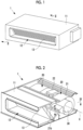
Fig. 1 is a perspective view of an air conditioner equipped with a blower according to an embodiment of the present disclosure. -
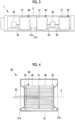
Fig. 2 is a cross-sectional view of the air conditioner taken along a cutting line II-II shown inFig. 1 . -
Fig. 3 is a rear view of the air conditioner equipped with the blower according to the embodiment of the present disclosure. -
Fig. 4 is a longitudinal sectional view of the blower taken along a cutting line IV-IV shown inFig. 2 . -
Fig. 5 is a perspective view of an impeller according to the embodiment of the present disclosure. -
Fig. 6 is a side view of the impeller as viewed from a direction of an arrow A shown inFig. 5 . -
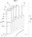
Fig. 7 is a partial perspective view of the impeller according to the embodiment of the present disclosure as viewed from an inside. -
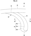
Fig. 8 is an enlarged view of a portion B of the impeller shown inFig. 6 . -
Fig. 9 is a longitudinal sectional view of a blade taken along a cutting line IX-IX shown inFig. 8 . -
Fig. 10 is a longitudinal sectional view of the blade in which a gap between the blades is shown. -
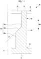
Fig. 11 is another example of the longitudinal sectional view of the blade in the cutting line IX-IX shown inFig. 8 . -
Fig. 12 is a partial perspective view of the impeller according to the embodiment of the present disclosure as viewed from the inside. -
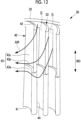
Fig. 13 is an enlarged view of Modification Example 2 of the portion B of the impeller shown inFig. 6 . -
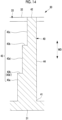
Fig. 14 is a longitudinal sectional view of the blade taken along a cutting line XIV-XIV shown inFig. 13 . -
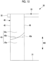
Fig. 15 is a view of a blade of an impeller according to Modification Example 3 as viewed from a pressure surface side. - Hereinafter, an impeller and a blower according to an embodiment of the present disclosure will be described with reference to the drawings.
- A
blower 20 is a sirocco fan that sends out air by rotating animpeller 30, and is mounted on, for example, an air conditioner indoor unit ofceiling duct type 1. - As shown in
Figs. 1 to 3 , theair conditioner 1 includes ahousing 11, aheat exchanger 13, and theblower 20. - The
housing 11 is, for example, an outer box configured in a rectangular parallelepiped shape, and theheat exchanger 13 and theblower 20 are accommodated and installed in an internal space thereof. - An
air outlet 12 is open on a front surface of thehousing 11, and is configured to blow out air that has been sent from theblower 20 and passed through theheat exchanger 13. - The
heat exchanger 13 is a device that performs heat exchange between a refrigerant and air, and extends along a longitudinal direction of thehousing 11. - The
heat exchanger 13 is disposed on theair outlet 12 side (a front surface side of the housing 11) inside thehousing 11. - The
blower 20 is a device that sends out air by rotating theimpeller 30, as described above. - The
blower 20 is disposed on a back surface side of theheat exchanger 13 inside thehousing 11. By disposing theblower 20 in this way, the air sent out from theblower 20 passes through theheat exchanger 13. - A plurality of
blowers 20 may be installed along the longitudinal direction of theheat exchanger 13, and in the case ofFig. 3 , threeblowers 20 are installed. - The
blower 20 includes theimpeller 30, avolute casing 21, anelectric motor 22, and adrive shaft 23. - The
impeller 30 is a component having a substantially tubular outer shape centered on an axis X, in which a plurality ofblades 40 are disposed at intervals around the axis X. - A detailed configuration of the
impeller 30 will be described later. - The
volute casing 21 is a container having a known scroll shape and accommodating theimpeller 30. - As shown in
Figs. 2 and4 , abell mouth 21a and adischarge port 21b are formed in thevolute casing 21. Air outside thevolute casing 21 is taken into through thebell mouth 21a while being rectified by the rotatingimpeller 30. In addition, the air discharged from the rotatingimpeller 30 is rectified and pressurized inside thevolute casing 21 and is sent out from thedischarge port 21b. - As shown in
Figs. 2 and3 , theelectric motor 22 is a device for rotating theimpeller 30 around the axis X via thedrive shaft 23. - The
drive shaft 23 is connected to acenter plate 31 of theimpeller 30, which will be described later. Accordingly, the driving force (rotation) of thedrive shaft 23 connected to theelectric motor 22 is transmitted to theimpeller 30. - The
electric motor 22 does not need to correspond to theimpeller 30 on a one-to-one basis, and twoimpellers 30 may be rotated by oneelectric motor 22. In this case, for example, theimpellers 30 are disposed on both sides of theelectric motor 22. In addition, three ormore impellers 30 may be rotated by oneelectric motor 22. - As shown in
Figs. 5 to 7 , theimpeller 30 includes thecenter plate 31, ashroud ring 32, and a plurality ofblades 40, and has a substantially tubular outer shape centered on the axis X. - The
impeller 30 rotates in a direction of an arrow R shown in, for example,Fig. 5 orFig. 6 with the axis X as a rotation center. - The
impeller 30 is made of resin or metal, and may be integrally molded by, for example, injection molding, or may be configured by assembling a plurality of components. - Here, the
impeller 30 shown inFig. 5 is of a type including two shroud rings 32 on both sides of thecenter plate 31. However, theimpeller 30 according to the present invention is not limited to this type and may be, for example, a type including oneshroud ring 32. - The
center plate 31 is a disk-shaped portion centered on the axis X. - As shown in
Figs. 5 and6 , thedrive shaft 23 connected to theelectric motor 22 is connected to the center of thecenter plate 31. In this case, the axis X coincides with a rotational axis of thedrive shaft 23. - The
shroud ring 32 is an annular portion centered on the axis X. - The
shroud ring 32 is disposed to be spaced from thecenter plate 31 in the direction of the axis X and to face thecenter plate 31 in parallel. - The
shroud ring 32 is disposed to face thebell mouth 21a, and the air taken into the inside of the volute casing 21 from thebell mouth 21a flows into an inner region (a region surrounded by the blades 40) of theimpeller 30 from a suction port 33 (an inner region of the shroud ring 32). That is, theshroud ring 32 defines thesuction port 33 for air in theimpeller 30. - As shown in
Figs. 5 to 7 , theblade 40 is disposed in parallel with the axis X between an outer peripheral edge of thecenter plate 31 and theshroud ring 32, and a blade width direction WD is along the direction of the axis X. Here, a blade end on thecenter plate 31 side in the blade width direction WD is referred to as abase end 41, and a blade end on theshroud ring 32 side in the blade width direction WD is referred to as atip 42. - The
blades 40 are disposed at predetermined intervals (gaps G) around the axis X. The gap G is an opening for discharging the air that has flowed into the inside of the impeller 30 (the inside region surrounded by all the blades 40) to the outside of theimpeller 30. - As shown in
Figs. 6 to 9 , theblade 40 has apressure surface 43 and asuction surface 44 as blade surfaces, and the cross-sectional shape thereof is a streamline shape. - The term "cross section" as referred to herein means a cross section in a plane orthogonal to the axis X.
- The
pressure surface 43 is a blade surface that is located at the front with respect to a rotation direction of theimpeller 30. - In addition, the
suction surface 44 is a blade surface that is located at the back with respect to the rotation direction of theimpeller 30. - The
suction surface 44 is, for example, a smooth surface continuous in the blade width direction WD, and is substantially parallel to the axis X in the blade width direction WD. - The
pressure surface 43 has, for example, a base end-side surface 43a (a center plate-side surface), a bladethickness change surface 43b, and a tip-side surface 43c (a shroud ring-side surface), and these surfaces are connected to each other to form onepressure surface 43. - The base end-
side surface 43a is a surface located in a region on thebase end 41 side of the blade 40 (a region closer to thebase end 41 with respect to the bladethickness change surface 43b in the blade 40), one end of which is connected to thecenter plate 31, and the other end of which is connected to an edge of the bladethickness change surface 43b. - The base end-
side surface 43a is, for example, a surface substantially parallel to the axis X in the blade width direction WD. Therefore, the portion (range) of theblade 40 corresponding to the base end-side surface 43a has a substantially constant blade thickness in the blade width direction WD. - The blade
thickness change surface 43b is a surface located in a substantially central region of theblade 40, one end of which is connected to an edge of the base end-side surface 43a, and the other end of which is connected to an edge of the tip-side surface 43c. - The blade
thickness change surface 43b is a surface that changes a blade thickness of theblade 40 in the blade width direction WD from thecenter plate 31 toward theshroud ring 32. Details of the bladethickness change surface 43b will be described later. - The tip-
side surface 43c is a surface located in a region on thetip 42 side of the blade 40 (a region closer to thetip 42 with respect to the bladethickness change surface 43b in the blade 400), one end of which is connected to an edge of the bladethickness change surface 43b, and an outer edge of the other end of which is connected to theshroud ring 32. - The tip-
side surface 43c is, for example, a surface substantially parallel to the axis X in the blade width direction WD. Therefore, the portion (range) of theblade 40 corresponding to the tip-side surface 43c has a substantially constant blade thickness in the blade width direction WD. However, the blade thickness is thinner than the blade thickness of the portion of theblade 40 corresponding to the base end-side surface 43a. - As shown in
Figs. 7 to 9 , the bladethickness change surface 43b is a surface in which an angle with respect to the axis X in the blade width direction WD changes with respect to angles of the base end-side surface 43a and the tip-side surface 43c (an angle with respect to the axis X in the blade width direction WD). - For example, in a case where the base end-
side surface 43a and the tip-side surface 43c are surfaces substantially parallel to the axis X in the blade width direction WD, the bladethickness change surface 43b is not a surface substantially parallel to the axis X in the blade width direction WD, but is a surface inclined with respect to the axis X in the blade width direction WD. - Accordingly, the blade thickness of the
blade 40 changes in the blade width direction WD from thecenter plate 31 toward theshroud ring 32. Specifically, the blade thickness of the portion of theblade 40 corresponding to the tip-side surface 43c is thinner than the blade thickness of the portion of theblade 40 corresponding to the base end-side surface 43a. That is, when theblade 40 is viewed from the direction of the axis X, the cross-sectional shape of the portion of theblade 40 corresponding to the tip-side surface 43c falls within the range of the cross-sectional shape of the portion of theblade 40 corresponding to the base end-side surface 43a. - The term "blade thickness" as referred to herein means, for example, a maximum blade thickness or a blade thickness in the same longitudinal cross section.
- Here, the expression "(blade thickness is) thinner" will be described using a specific example.
- As a first example, the blade thickness of the portion of the
blade 40 corresponding to the tip-side surface 43c is set to a blade thickness in a range of about 50% to 70% of the blade thickness of the portion of theblade 40 corresponding to the base end-side surface 43a. - As a second example, the tip-
side surface 43c is offset to thesuction surface 44 side along a normal direction with respect to the base end-side surface 43a, and the offset amount is in a range of 30% to 50% of the maximum blade thickness. For example, in a case where the maximum blade thickness is 4 mm, the tip-side surface 43c is uniformly offset by 2 mm. - In addition, as shown in
Fig. 10 , since the blade thickness of the portion of theblade 40 corresponding to the tip-side surface 43c is thinner than the blade thickness of the portion of theblade 40 corresponding to the base end-side surface 43a, when the gap G between theblades 40 adjacent to each other is viewed, the gap G in the region corresponding to the tip-side surface 43c is larger than the gap G in the region corresponding to the base end-side surface 43a. - The blade
thickness change surface 43b may be a surface perpendicular to the axis X, as shown inFig. 9 , and may be a surface inclined with respect to the axis X, as shown inFig. 11 . - In a case where the blade
thickness change surface 43b is a surface perpendicular to the axis X, a level difference is generated on thepressure surface 43 due to the bladethickness change surface 43b. - As shown in
Fig. 11 , in a case where the bladethickness change surface 43b is a surface inclined with respect to the axis X, a gradient is generated on thepressure surface 43 due to the bladethickness change surface 43b. An angle θ of the gradient is preferably, for example, 45 degrees or larger and 90 degrees or smaller with respect to the axis X. In a case where the angle θ of the gradient is 90 degrees, the bladethickness change surface 43b is a surface perpendicular to the axis X (refer toFig. 9 ). - In any case, the blade
thickness change surface 43b is a protrusion portion/hooking portion of thepressure surface 43 in the blade width direction WD from theshroud ring 32 toward thecenter plate 31. - As the
impeller 30 rotates, air is taken into the inside of thevolute casing 21 via thebell mouth 21a. - The air taken into the inside of the
volute casing 21 flows into an inner region (a region surrounded by the blades 40) of theimpeller 30 along the direction of the axis X from thesuction port 33 of theimpeller 30. - The air that has flowed into the inner region of the
impeller 30 is discharged from each gap G with a centrifugal force by theblades 40 disposed annularly integrally rotating around the axis X. - The air discharged from the gap G is rectified and pressurized in the inside of the
volute casing 21 and is sent out from thedischarge port 21b. - Here, since the
blade 40 of theimpeller 30 according to the present embodiment is provided with the bladethickness change surface 43b, the following flow is formed when the air is discharged from each gap G. - As shown in
Fig. 12 , part of the air that has flowed into the inner region of theimpeller 30 along the direction of the axis X flows along thepressure surface 43 of theblade 40. - In this case, the air flowing from the
shroud ring 32 toward thecenter plate 31 on thepressure surface 43 collides with the bladethickness change surface 43b. As a result, the direction of the flow of the air is turned to the outer side in the radial direction (a radial direction with respect to the axis X). Therefore, the air is actively discharged to the outside of theimpeller 30 from the gap G in a region in the vicinity of the bladethickness change surface 43b. - In addition, since the gap G in the region corresponding to the tip-
side surface 43c is larger than the gap G in the region corresponding to the base end-side surface 43a, the air is actively discharged from the gap G in the region corresponding to the tip-side surface 43c to the outside of theimpeller 30. - On the contrary, the gap G in the region corresponding to the base end-
side surface 43a is smaller than the gap G in the region corresponding to the tip-side surface 43c. Therefore, compared to the gap G corresponding to the tip-side surface 43c, the air is less likely to be discharged from the gap G corresponding to the base end-side surface 43a due to the influence of the flow path resistance. - In the blade width direction WD, when the position of the
tip 42 of theblade 40 is set to 0% and the position of thebase end 41 is set to 100%, the bladethickness change surface 43b is provided in a range of 25% or more and 75% or less, and preferably in a range of 25% or more and 60% or less. - <Modification Example 2>
- As shown in
Figs. 13 and14 , the bladethickness change surface 43b may be provided at a plurality of locations on thepressure surface 43 along the blade width direction WD. - In a case where an upper blade thickness change surface in
Fig. 14 is denoted by areference numeral 43b and a lower blade thickness change surface is denoted by a reference numeral 43b', thepressure surface 43 between the bladethickness change surface 43b and the bladethickness change surface 43b' is regarded as anintermediate surface 43d. - In this case, in a case where the blade
thickness change surface 43b is used as a reference, theintermediate surface 43d corresponds to a center plate-side surface, and the tip-side surface 43c corresponds to a shroud ring-side surface. On the other hand, in a case where the bladethickness change surface 43b' is used as a reference, theintermediate surface 43d corresponds to a shroud ring-side surface, and the base end-side surface 43a corresponds to a center plate-side surface. - In the case of the present modification example, at least one of the plurality of blade thickness change surfaces 43b may be provided in a range of 25% or more and 75% or less, and preferably in a range of 25% or more and 60% or less.
- As shown in
Fig. 15 , the bladethickness change surface 43b may be inclined from theshroud ring 32 side toward thecenter plate 31 side over a range from a leadingedge 46 to a trailingedge 45 of theblade 40. - A two-dot chain line shown in
Fig. 15 indicates a bladethickness change surface 43b in a normal state where the inclination is not given (shown for reference). - According to the present embodiment, the following effects are obtained.
- The air flowing from the
shroud ring 32 toward thecenter plate 31 on thepressure surface 43 collides with the bladethickness change surface 43b. As a result, the direction of the flow of the air is turned to the outer side in the radial direction. Therefore, the air is actively discharged to the outside of theimpeller 30 from the gap G in a region in the vicinity of the bladethickness change surface 43b. Accordingly, it is possible to suppress the phenomenon in which the region in which the air is discharged is biased toward thecenter plate 31 side. - In addition, since the gap G in the region corresponding to the tip-
side surface 43c is larger than the gap G in the region corresponding to the base end-side surface 43a, the air is actively discharged from the gap G in the region corresponding to the tip-side surface 43c to the outside of theimpeller 30. On the contrary, compared to the gap G corresponding to the tip-side surface 43c, the air is less likely to be discharged from the gap G corresponding to the base end-side surface 43a due to the influence of the flow path resistance. Accordingly, it is possible to suppress the phenomenon in which the region in which the air is discharged is biased toward thecenter plate 31 side. - As described above, by suppressing the phenomenon in which the region in which the air is discharged is biased toward the
center plate 31 side, the bias of the flow velocity in the inside of thevolute casing 21 accommodating theimpeller 30 is improved, and for example, the static pressure efficiency can be improved by suppressing a blowing loss occurring due to the generation of a swirling flow caused by the bias of the wind speed, or a decrease in heat exchange performance can be suppressed by making the wind speed distribution of the air blown from thevolute casing 21 toward theheat exchanger 13 uniform. - In addition, since the blade thickness on the
shroud ring 32 side is thinner than that on thecenter plate 31 side, when theblade 40 is injection-molded, it is possible to easily perform mold releasing in the direction of the axis X by using a mold having a simple shape. Therefore, the manufacturing cost of theimpeller 30 can be reduced. - In addition, the blade
thickness change surface 43b is a surface perpendicular to the axis X, so that the direction of the flow of air can be rapidly turned. - In addition, the
suction surface 44 is a smooth surface continuous in the blade width direction WD, so that a draft angle required for mold releasing during injection molding can be provided on thesuction surface 44 side. - In addition, the blade
thickness change surface 43b is located in a range of 25% or more and 60% or less, so that a region where air is easily discharged can be brought closer to theshroud ring 32 side. - In addition, the blade
thickness change surface 43b is provided at a plurality of locations on thepressure surface 43 along the blade width direction WD, so that, for example, even with respect to theimpeller 30 having a large blade width with respect to the diameter of theimpeller 30, the same effect can be obtained. - In addition, the blade
thickness change surface 43b is inclined from theshroud ring 32 side toward thecenter plate 31 side over a range from the leadingedge 46 to the trailingedge 45 of theblade 40, so that the direction of the flow of the air flowing in from thesuction port 33 can be smoothly turned. Therefore, it is possible to reduce a loss when the direction is turned, and it is possible to further improve the static pressure efficiency. - In addition, the area (the area in contact with air) of the blade
thickness change surface 43b is increased by an amount corresponding to the inclination, and the direction of the flow of air can be efficiently changed. - In addition, it is possible to suppress deterioration of aerodynamic noise associated with the sudden turning of the direction of the flow.
- In addition, the input of the
electric motor 22 can be reduced due to theimpeller 30 in which the static pressure efficiency is improved. - The
suction surface 44 may be provided with the same configuration as the bladethickness change surface 43b. - In addition, when the
blade 40 is viewed from the direction of the axis X, a blade outlet angle of the portion of theblade 40 corresponding to the tip-side surface 43c and a blade outlet angle of the portion of theblade 40 corresponding to the base end-side surface 43a may be different from each other in a range in which the cross-sectional shape of the portion of theblade 40 corresponding to the tip-side surface 43c fits into the cross-sectional shape of the portion of theblade 40 corresponding to the base end-side surface 43a. - The impeller and the blower according to the embodiment described above are understood as follows, for example.
- An impeller (30) according to a first aspect of the present disclosure is an impeller having a rotation center on an axis (X), including: an annular shroud ring (32) that forms an air suction port (33) and is centered on the axis; a disk-shaped center plate (31) that is provided to face the shroud ring and is centered on the axis; and a plurality of blades (40), each of which has a blade width along a direction of the axis between the shroud ring and the center plate, and which are disposed around the axis at predetermined intervals, in which a blade surface (43) of each of the blades has, in a blade width direction (WD), a blade thickness change surface (43b), a base end-side surface (43a) connected to the center plate side of the blade thickness change surface, and a tip-side surface (43c) connected to the shroud ring side of the blade thickness change surface, and in the blade thickness change surface, an angle of the blade surface with respect to the axis in the blade width direction changes with respect to angles of the base end-side surface and the tip-side surface such that a blade thickness on the center plate side with respect to the blade thickness change surface is thicker than a blade thickness on the shroud ring side with respect to the blade thickness change surface.
- According to the impeller of the present aspect, the blade surface has, in the blade width direction, the blade thickness change surface, the base end-side surface connected to the center plate side of the blade thickness change surface, and the tip-side surface connected to the shroud ring side of the blade thickness change surface, and in the blade thickness change surface, the angle of the blade surface with respect to the axis in the blade width direction changes with respect to the angles of the base end-side surface and the tip-side surface such that the blade thickness on the center plate side with respect to the blade thickness change surface is thicker than the blade thickness on the shroud ring side with respect to the blade thickness change surface. Therefore, part of the air that flows in from a suction port formed in the shroud ring collides with the blade thickness change surface along the direction of the axis, so that the direction of the flow is turned to the outer side in the radial direction. Therefore, part of the air can be discharged to the outer side in the radial direction in the region corresponding to the tip-side surface of the blade. Accordingly, it is possible to suppress the phenomenon in which the region in which the air is discharged is biased toward the center plate side.
- In addition, since the blade thickness on the shroud ring side is thinner than that on the center plate side, the gap (G) between the blades adjacent to each other is large on the shroud ring side, so that air flows easily, whereas the gap on the center plate side is small, so that air is difficult to flow due to the flow path resistance. Accordingly, it is possible to suppress the phenomenon in which the region in which the air is discharged is biased toward the center plate side.
- As described above, by suppressing the phenomenon in which the region in which the air is discharged is biased toward the center plate side, the bias of the flow velocity in the inside of the casing (21) accommodating the impeller is improved, and for example, the static pressure efficiency can be improved by suppressing a blowing loss occurring due to the generation of a swirling flow caused by the bias of the wind speed, or a decrease in heat exchange performance can be suppressed by making the wind speed distribution of the air blown from the casing toward the heat exchanger (13) uniform.
- In addition, since the blade thickness on the shroud ring side is thinner than that on the center plate side, when the blade is injection-molded, it is possible to easily perform mold releasing in the direction of the axis by using a mold having a simple shape. Therefore, the manufacturing cost of the impeller can be reduced.
- In addition, in an impeller according to a second aspect of the present disclosure, in the first aspect, the blade thickness change surface is a surface substantially perpendicular to the axis.
- According to the impeller according to the present aspect, since the blade thickness change surface is a surface substantially perpendicular to the axis, the direction of the flow of the air flowing in from the suction port can be rapidly turned by a stepped surface.
- In addition, in an impeller according to a third aspect of the present disclosure, in the first or second aspect, a suction surface (44) of the blade surface is a smooth surface continuous in the blade width direction.
- According to the impeller according to the present aspect, since the suction surface is a smooth surface continuous in the blade width direction, a draft angle required for mold releasing during injection molding can be provided on the suction surface side.
- In addition, in an impeller according to a fourth aspect of the present disclosure, in any one of the first to third aspects, in the blade width direction, when a position of an end portion (42) of the blade on the shroud ring side is set to 0% and a position of an end portion (41) of the blade on the center plate side is set to 100%, the blade thickness change surface is located in a range of 25% or more and 60% or less.
- According to the impeller according to the present aspect, in the blade width direction, when the position of the end portion of the blade on the shroud ring side is set to 0% and the position of the end portion of the blade on the center plate side is set to 100%, the blade thickness change surface is located in a range of 25% or more and 60% or less. Therefore, the region where air is easily discharged can be brought closer to the shroud ring side.
- In addition, in an impeller according to a fifth aspect of the present disclosure, in any one of the first to fourth aspects, the blade thickness change surface is provided at a plurality of locations on the blade surface along the blade width direction.
- According to the impeller according to the present aspect, since the blade thickness change surface is provided at a plurality of locations on the blade surface along the blade width direction, the same effect can be obtained even with respect to an impeller having a large blade width with respect to the diameter of the impeller, for example.
- In addition, in an impeller according to a sixth aspect of the present disclosure, in any one of the first to fifth aspects, the blade thickness change surface is inclined from the shroud ring side toward the center plate side over a range from a leading edge to a trailing edge of the blade.
- According to the impeller according to the present aspect, since the blade thickness change surface is inclined from the shroud ring side toward the center plate side over a range of the leading edge to the trailing edge of the blade, the direction of the flow of the air flowing in from the suction port can be smoothly turned. Therefore, it is possible to reduce a loss when the direction is turned, and it is possible to further improve the static pressure efficiency.
- In addition, the area of the blade thickness change surface (the area that can be in contact with air) is increased by an amount corresponding to the inclination, and the direction of the flow of air can be efficiently changed.
- In addition, it is possible to suppress deterioration of aerodynamic noise associated with the sudden turning of the direction of the flow.
- In addition, a blower (20) according to a seventh aspect of the present disclosure includes the impeller according to any one of the first to sixth aspects, and a drive unit (22) that rotates the impeller around the axis.
- According to the blower according to the present aspect, since the blower includes the impeller described above and the drive unit that rotationally drives the impeller around the axis, the input (consumed power) of the drive unit can be reduced due to the impeller with improved static pressure efficiency.
- In addition, an air conditioner (1) according to an eighth aspect of the present disclosure includes the blower according to the sixth aspect, and a heat exchanger (13).
- According to the air conditioner according to the present aspect, since the air conditioner includes the blower described above and the heat exchanger, in a case where the wind speed distribution of the air that is blown from the casing toward the heat exchanger is uniform, a decrease in heat exchange performance can be suppressed. Reference Signs List
-
- 1: air conditioner
- 11: housing
- 12: air outlet
- 13: heat exchanger
- 20: blower
- 21: volute casing
- 21a: bell mouth
- 21b: discharge port
- 22: electric motor (drive unit)
- 23: drive shaft
- 30: impeller
- 31: center plate
- 32: shroud ring
- 33: suction port
- 40: blade
- 41: base end (blade end on center plate side)
- 42: tip (blade end on shroud ring side)
- 43: pressure surface
- 43a: base end-side surface (center plate-side surface)
- 43b, 43b': blade thickness change surface
- 43c: tip-side surface (shroud ring-side surface)
- 43d: intermediate surface
- 44: suction surface
- 45: trailing edge
- 46: leading edge
- G: gap
- X: axis
Claims (8)
- An impeller having a rotation center on an axis, comprising:an annular shroud ring that forms an air suction port and is centered on the axis;a disk-shaped center plate that is provided to face the shroud ring and is centered on the axis; anda plurality of blades, each of which has a blade width along a direction of the axis between the shroud ring and the center plate, and which are disposed around the axis at predetermined intervals,wherein a blade surface of each of the blades has, in a blade width direction, a blade thickness change surface, a center plate-side surface connected to a center plate side of the blade thickness change surface, and a shroud ring-side surface connected to a shroud ring side of the blade thickness change surface, andin the blade thickness change surface, an angle of the blade surface with respect to the axis in the blade width direction changes with respect to angles of the center plate-side surface and the shroud ring-side surface such that a blade thickness on the center plate side with respect to the blade thickness change surface is thicker than a blade thickness on the shroud ring side with respect to the blade thickness change surface.
- The impeller according to Claim 1,
wherein the blade thickness change surface is a surface substantially perpendicular to the axis. - The impeller according to Claim 1 or 2,
wherein a suction surface of the blade surface is a smooth surface continuous in the blade width direction. - The impeller according to Claim 1 or 2,
wherein, in the blade width direction, when a position of an end portion of the blade on the shroud ring side is set to 0% and a position of an end portion of the blade on the center plate side is set to 100%, the blade thickness change surface is located in a range of 25% or more and 75% or less. - The impeller according to Claim 1 or 2,
wherein the blade thickness change surface is provided at a plurality of locations on the blade surface along the blade width direction. - The impeller according to Claim 1 or 2,
wherein the blade thickness change surface is inclined from the shroud ring side to the center plate side over a range from a leading edge to a trailing edge of the blade. - A blower comprising:the impeller according to Claim 1; anda drive unit that rotates the impeller around the axis.
- An air conditioner comprising:the blower according to Claim 7; anda heat exchanger.
Applications Claiming Priority (2)
| Application Number | Priority Date | Filing Date | Title |
|---|---|---|---|
| JP2022139969A JP2024035484A (en) | 2022-09-02 | 2022-09-02 | Impellers, blowers and air conditioners |
| PCT/JP2023/032031 WO2024048769A1 (en) | 2022-09-02 | 2023-08-31 | Impeller, blower, and air conditioner |
Publications (2)
| Publication Number | Publication Date |
|---|---|
| EP4563826A1 true EP4563826A1 (en) | 2025-06-04 |
| EP4563826A4 EP4563826A4 (en) | 2025-12-03 |
Family
ID=90097969
Family Applications (1)
| Application Number | Title | Priority Date | Filing Date |
|---|---|---|---|
| EP23860531.5A Pending EP4563826A4 (en) | 2022-09-02 | 2023-08-31 | IRON, BLOWER AND AIR CONDITIONER |
Country Status (5)
| Country | Link |
|---|---|
| EP (1) | EP4563826A4 (en) |
| JP (1) | JP2024035484A (en) |
| CN (1) | CN119677964A (en) |
| AU (1) | AU2023335197B2 (en) |
| WO (1) | WO2024048769A1 (en) |
Family Cites Families (5)
| Publication number | Priority date | Publication date | Assignee | Title |
|---|---|---|---|---|
| US6761539B2 (en) * | 2002-07-24 | 2004-07-13 | Ventilatoren Sirocco Howden B.V. | Rotor blade with a reduced tip |
| WO2007138673A1 (en) * | 2006-05-30 | 2007-12-06 | Mitsubishi Electric Corporation | Centrifugal multi-blade fan |
| US10634168B2 (en) | 2015-10-07 | 2020-04-28 | Mitsubishi Electric Corporation | Blower and air-conditioning apparatus including the same |
| JP2017180238A (en) * | 2016-03-30 | 2017-10-05 | 株式会社ケーヒン | Sirocco fan and centrifugal blower |
| JP7608825B2 (en) * | 2020-12-24 | 2025-01-07 | 株式会社富士通ゼネラル | Multi-blade fan and indoor unit |
-
2022
- 2022-09-02 JP JP2022139969A patent/JP2024035484A/en active Pending
-
2023
- 2023-08-31 CN CN202380061725.9A patent/CN119677964A/en active Pending
- 2023-08-31 WO PCT/JP2023/032031 patent/WO2024048769A1/en not_active Ceased
- 2023-08-31 AU AU2023335197A patent/AU2023335197B2/en active Active
- 2023-08-31 EP EP23860531.5A patent/EP4563826A4/en active Pending
Also Published As
| Publication number | Publication date |
|---|---|
| CN119677964A (en) | 2025-03-21 |
| AU2023335197B2 (en) | 2026-03-05 |
| WO2024048769A1 (en) | 2024-03-07 |
| EP4563826A4 (en) | 2025-12-03 |
| JP2024035484A (en) | 2024-03-14 |
| AU2023335197A1 (en) | 2025-03-13 |
Similar Documents
| Publication | Publication Date | Title |
|---|---|---|
| US7244099B2 (en) | Multi-vane centrifugal fan | |
| KR100548036B1 (en) | Axial fan shroud assembly with guide vane for axial fan and its guide vane | |
| US20070251680A1 (en) | Centrifugal Blower and Air Conditioner with Centrifugal Blower | |
| WO2012008238A1 (en) | Multi-vane centrifugal fan and air conditioning facility using same | |
| US10644363B2 (en) | Temperature conditioning unit, temperature conditioning system, and vehicle | |
| JP7308985B2 (en) | Centrifugal blower and air conditioner | |
| CN101313153B (en) | Multi-blade blower | |
| WO2022217957A1 (en) | Axial radial flow blower and air conditioning device | |
| JP7466683B2 (en) | Multi-blade centrifugal blower | |
| CN110506164B (en) | Propeller fans and outdoor units for air conditioners | |
| US10473113B2 (en) | Centrifugal blower | |
| CN113439163A (en) | Centrifugal blower and air conditioner using same | |
| KR20070101642A (en) | Turbo fan | |
| AU2023335197A1 (en) | Impeller, blower, and air conditioner | |
| JP2002005091A (en) | Multi-wing fan | |
| WO2020110967A1 (en) | Propeller fan | |
| JP7446469B2 (en) | multi-blade centrifugal blower | |
| JP2024126872A (en) | Centrifugal fans and air conditioners | |
| CN115773262A (en) | Axial flow fan | |
| CN108661950B (en) | Volute, fan and refrigeration equipment | |
| KR100572863B1 (en) | Turbo Fans for Air Conditioners | |
| JP7292549B2 (en) | Impeller and multi-blade blower | |
| WO2020110969A1 (en) | Propeller fan | |
| WO2020110968A1 (en) | Propeller fan | |
| JP7655094B2 (en) | Centrifugal Blower |
Legal Events
| Date | Code | Title | Description |
|---|---|---|---|
| STAA | Information on the status of an ep patent application or granted ep patent |
Free format text: STATUS: THE INTERNATIONAL PUBLICATION HAS BEEN MADE |
|
| PUAI | Public reference made under article 153(3) epc to a published international application that has entered the european phase |
Free format text: ORIGINAL CODE: 0009012 |
|
| STAA | Information on the status of an ep patent application or granted ep patent |
Free format text: STATUS: REQUEST FOR EXAMINATION WAS MADE |
|
| 17P | Request for examination filed |
Effective date: 20250226 |
|
| AK | Designated contracting states |
Kind code of ref document: A1 Designated state(s): AL AT BE BG CH CY CZ DE DK EE ES FI FR GB GR HR HU IE IS IT LI LT LU LV MC ME MK MT NL NO PL PT RO RS SE SI SK SM TR |
|
| A4 | Supplementary search report drawn up and despatched |
Effective date: 20251031 |
|
| RIC1 | Information provided on ipc code assigned before grant |
Ipc: F04D 29/30 20060101AFI20251027BHEP |
|
| DAV | Request for validation of the european patent (deleted) | ||
| DAX | Request for extension of the european patent (deleted) |