EP4563821A1 - Bearing for pump - Google Patents
Bearing for pump Download PDFInfo
- Publication number
- EP4563821A1 EP4563821A1 EP24216108.1A EP24216108A EP4563821A1 EP 4563821 A1 EP4563821 A1 EP 4563821A1 EP 24216108 A EP24216108 A EP 24216108A EP 4563821 A1 EP4563821 A1 EP 4563821A1
- Authority
- EP
- European Patent Office
- Prior art keywords
- bearing component
- bearing
- pump
- gears
- axial
- Prior art date
- Legal status (The legal status is an assumption and is not a legal conclusion. Google has not performed a legal analysis and makes no representation as to the accuracy of the status listed.)
- Pending
Links
Images





Classifications
-
- F—MECHANICAL ENGINEERING; LIGHTING; HEATING; WEAPONS; BLASTING
- F04—POSITIVE - DISPLACEMENT MACHINES FOR LIQUIDS; PUMPS FOR LIQUIDS OR ELASTIC FLUIDS
- F04C—ROTARY-PISTON, OR OSCILLATING-PISTON, POSITIVE-DISPLACEMENT MACHINES FOR LIQUIDS; ROTARY-PISTON, OR OSCILLATING-PISTON, POSITIVE-DISPLACEMENT PUMPS
- F04C2/00—Rotary-piston machines or pumps
- F04C2/08—Rotary-piston machines or pumps of intermeshing-engagement type, i.e. with engagement of co-operating members similar to that of toothed gearing
- F04C2/12—Rotary-piston machines or pumps of intermeshing-engagement type, i.e. with engagement of co-operating members similar to that of toothed gearing of other than internal-axis type
- F04C2/14—Rotary-piston machines or pumps of intermeshing-engagement type, i.e. with engagement of co-operating members similar to that of toothed gearing of other than internal-axis type with toothed rotary pistons
- F04C2/18—Rotary-piston machines or pumps of intermeshing-engagement type, i.e. with engagement of co-operating members similar to that of toothed gearing of other than internal-axis type with toothed rotary pistons with similar tooth forms
-
- F—MECHANICAL ENGINEERING; LIGHTING; HEATING; WEAPONS; BLASTING
- F04—POSITIVE - DISPLACEMENT MACHINES FOR LIQUIDS; PUMPS FOR LIQUIDS OR ELASTIC FLUIDS
- F04C—ROTARY-PISTON, OR OSCILLATING-PISTON, POSITIVE-DISPLACEMENT MACHINES FOR LIQUIDS; ROTARY-PISTON, OR OSCILLATING-PISTON, POSITIVE-DISPLACEMENT PUMPS
- F04C15/00—Component parts, details or accessories of machines, pumps or pumping installations, not provided for in groups F04C2/00 - F04C14/00
- F04C15/0003—Sealing arrangements in rotary-piston machines or pumps
- F04C15/0023—Axial sealings for working fluid
- F04C15/0026—Elements specially adapted for sealing of the lateral faces of intermeshing-engagement type machines or pumps, e.g. gear machines or pumps
-
- F—MECHANICAL ENGINEERING; LIGHTING; HEATING; WEAPONS; BLASTING
- F04—POSITIVE - DISPLACEMENT MACHINES FOR LIQUIDS; PUMPS FOR LIQUIDS OR ELASTIC FLUIDS
- F04C—ROTARY-PISTON, OR OSCILLATING-PISTON, POSITIVE-DISPLACEMENT MACHINES FOR LIQUIDS; ROTARY-PISTON, OR OSCILLATING-PISTON, POSITIVE-DISPLACEMENT PUMPS
- F04C15/00—Component parts, details or accessories of machines, pumps or pumping installations, not provided for in groups F04C2/00 - F04C14/00
- F04C15/0042—Systems for the equilibration of forces acting on the machines or pump
-
- F—MECHANICAL ENGINEERING; LIGHTING; HEATING; WEAPONS; BLASTING
- F04—POSITIVE - DISPLACEMENT MACHINES FOR LIQUIDS; PUMPS FOR LIQUIDS OR ELASTIC FLUIDS
- F04C—ROTARY-PISTON, OR OSCILLATING-PISTON, POSITIVE-DISPLACEMENT MACHINES FOR LIQUIDS; ROTARY-PISTON, OR OSCILLATING-PISTON, POSITIVE-DISPLACEMENT PUMPS
- F04C2/00—Rotary-piston machines or pumps
- F04C2/08—Rotary-piston machines or pumps of intermeshing-engagement type, i.e. with engagement of co-operating members similar to that of toothed gearing
- F04C2/082—Details specially related to intermeshing engagement type machines or pumps
- F04C2/086—Carter
-
- F—MECHANICAL ENGINEERING; LIGHTING; HEATING; WEAPONS; BLASTING
- F04—POSITIVE - DISPLACEMENT MACHINES FOR LIQUIDS; PUMPS FOR LIQUIDS OR ELASTIC FLUIDS
- F04C—ROTARY-PISTON, OR OSCILLATING-PISTON, POSITIVE-DISPLACEMENT MACHINES FOR LIQUIDS; ROTARY-PISTON, OR OSCILLATING-PISTON, POSITIVE-DISPLACEMENT PUMPS
- F04C2240/00—Components
- F04C2240/30—Casings or housings
-
- F—MECHANICAL ENGINEERING; LIGHTING; HEATING; WEAPONS; BLASTING
- F04—POSITIVE - DISPLACEMENT MACHINES FOR LIQUIDS; PUMPS FOR LIQUIDS OR ELASTIC FLUIDS
- F04C—ROTARY-PISTON, OR OSCILLATING-PISTON, POSITIVE-DISPLACEMENT MACHINES FOR LIQUIDS; ROTARY-PISTON, OR OSCILLATING-PISTON, POSITIVE-DISPLACEMENT PUMPS
- F04C2240/00—Components
- F04C2240/50—Bearings
- F04C2240/56—Bearing bushings or details thereof
Definitions
- the invention relates to the technical field of a bearing assembly for supporting gears and sealing against fluid leakage.
- journal bearings may be used to support gears within fuel pumps.
- the journal bearings can be configured to provide some sealing against fluid leakage at the gears.
- a first axial force is applied to movable ones of the journal bearings to press the journal bearings towards the gears relative to the outer housing.
- An example journal bearing of this type is disclosed by US Patent Publication No. US2023/0033416 .
- a pump comprises a housing defining a gear chamber.
- the housing defines an inlet and an outlet in fluid communication with the gear chamber.
- a gear arrangement is disposed within the gear chamber and is configured to drive fluid from the inlet to the outlet.
- the gear arrangement includes at least two gears rotatable about corresponding axes of rotation and each of the two gears define first and second axial gear faces that face in opposite axial directions. Journals are coupled to the two gear and are aligned along the axes of the two gears.
- a first bearing structure includes an inboard end that opposes the first axial gear face of the two gears.
- first bearing structure defines a first set of through-openings for radially supporting the journals relative to the housing such that the journals are rotatable about the axes of rotation relative to the housing.
- a second bearing structure includes an inboard end that opposes the second axial gear face of the two gears.
- the second bearing structure defines a second set of through-openings for radially supporting the journals relative to the housing such that the journals are rotatable about the axes of rotation relative to the housing and the second bearing structure also defines an outboard end.
- the second bearing structure comprising a first bearing component which defines the inboard end and a second bearing component which defines the outboard end.
- the first bearing component is axially movable relative to the second bearing component and is configured for directing a first axial force toward the second axial gear face of the two gears.
- the second bearing component is configured to transfer radial load from the two gears to the housing and to prevent radially load from being applied through the first bearing component.
- the first bearing component and the second bearing component each define portions of the second set of through-openings.
- inventive aspects can relate to individual features and to combinations of features. It is to be understood that both the forgoing general description and the following detailed description are exemplary and explanatory only and are not restrictive of the broad inventive concepts upon which the embodiments disclosed herein are based.
- the bearing assembly can be configured to separate radial bearing functionality and axial sealing functionality into separate bearing components.
- the bearing assembly can include a first bearing component adapted for providing axial sealing against axial gear faces of the gears and a second bearing component for accommodating radial loading.
- the first bearing component is axially moveable relative to the second bearing component and is positioned axially between the second bearing component and the axial gear faces.
- the first bearing component is biased axially toward the axial gear faces and away from the second bearing component.
- the biasing can be provided by one or more springs and/or by fluid pressure.
- the second bearing component prevents or limits radial load from being applied to the first bearing component to prevent the first bearing component from being axially locked in place via friction.
- Figs. 1-3 illustrates a pump 100 (e.g., a fuel pump) in accordance with the principles of the present disclosure.
- the pump 100 is adapted to pump fluid (e.g., fuel) from an inlet 102 through a gear chamber 118 to an outlet 104.
- the inlet 102, the outlet 104 (shown in FIG. 2 ), and the gear chamber 118 (shown in FIG. 3 ) can be defined by a pump housing 116 which may include a main housing body 117 and a cover 126.
- the outlet pressure is significantly higher than the inlet pressure.
- a gear arrangement 108 is rotationally supported within the pump housing 116 and is configured for pumping fluid through the gear chamber 118 from the inlet 102 to the outlet 104.
- the pump 100 can include one or more pumping stages, with the gear arrangement 108 corresponding to one of the stages.
- the housing 116 may define multiple inlets 102 and/or multiple outlets 104.
- the gear arrangement 108 includes two intermeshed gears 114 each configured to rotate relative the housing 116 about a corresponding axis 115.
- the axes 115 are parallel and extend through the gear chamber 118.
- the gears 114 are mounted on journals 120 aligned along the axes 115.
- the gears 114 and the journals 120 are configured to rotate in unison with each other about the axes 115.
- one of the journals 120 is coupled to a driveshaft that drives rotation of the journals 120 and their corresponding gears 114 about the axes 115.
- the driveshaft drives one of the gears 114 and the gear 114 driven by the driveshaft drives the other of the two gears. Since only one gear needs to be driven, a single driveshaft can be used.
- the gears 114 each include first and second axial gear faces 119, 121 that face in opposite directions.
- the journals 120 are supported for rotation relative to the housing 116 by a first bearing structure 122 positioned adjacent the first axial gear faces 119 and a second bearing structure 123 positioned adjacent the second axial gear faces 121.
- the gears 114 can be axially pressed between the first and second bearing structures 122, 123 to control leakage across the first and second axial gear faces 119, 121.
- the first bearing structure 122 has a first axial bearing face 125 that opposes the first axial gear faces 119 and the second bearing structure 123 has a second axial bearing face 128 that opposes the second axial gear faces 121.
- the first bearing structure 122 includes through openings 127 for receiving the journals 120.
- the through openings 127 can be in fluid communication with the inlet 102 such that the through openings 127 are maintained at inlet pressure.
- the through openings 127 can extend axially through the first bearing structure 122 from an inboard end 141 to an outboard end 143.
- the inboard end 141 can define the first axial bearing face 125.
- the first bearing structure 122 is rotationally and axially fixed relative to the pump housing 116 and the journals 120 rotate within the through openings 127 relative to the first bearing structure 122.
- the term fixed means axial movement is not intended during use; however, no welding or fastening exists.
- the first bearing structure 122 may abut against a first stop within the housing 116 which limits axial movement away from the gears. Because the inlet pressure and discharge pressure may be different, an uneven radial load may be asserted on the gears. The radial load can be greatest in one radial direction as a result of the difference in pressure between the inlet 102 and the outlet 104. The radial load is then transferred from the gears 114 to the journals 120 and from the journals 120 through the first bearing structure 122 to the pump housing 116.
- the first bearing structure 122 can define circumferential grooves 129 about the axes 115 at peripheral portions of the inboard end 141.
- the circumferential grooves 129 are in fluid communication with the outlet 104 and can be configured to enhance the application of outlet pressure at the first axial bearing face 125.
- the first bearing structure 122 can define an inlet region 131 corresponding to the inlet 102 and an outlet region 133 corresponding to the outlet 104.
- the inlet and outlet regions 131, 133 can be positioned adjacent the first axial bearing face 125 and can be separated by a divider 165.
- the second bearing structure 123 includes through-openings 147 for receiving the journals 120.
- the through-openings 147 can be in fluid communication with the inlet 102 such that the through-openings 147 are maintained at inlet pressure.
- the second bearing structure 123 defines an inboard end 149 and an outboard end 151.
- the inboard end 149 defines the second axial bearing face 128.
- the through-openings 147 extend axially through the second bearing structure 123 from the inboard end 149 to the outboard end 151.
- the second bearing structure 123 has a multi-part construction with different bearing components being designed to provide different bearing functionality.
- the second bearing structure 123 can include a first bearing component 153 that defines the inboard end 149 and a second bearing component 155 that defines the outboard end 151.
- the first bearing component 153 can include the second axial bearing face 128 can be configured for applying an axial sealing force toward the second axial gear faces 121 for causing the first and second axial gear faces 119, 121 to be pressed axially between the first and second axial bearing faces 125, 127 of the first and second bearing structures 122, 123.
- a layer of pressurized fluid exists between second axial gear faces 121 and the second axial bearing face 128.
- the axial sealing force helps pressurize the fluid and maintain a minimal gap between the second axial gear face 121, and the second axial bearing face 128.
- the first bearing component 153 is preferably positioned axially between the second bearing component 155 and the second axial gear face 121 and is preferably axially moveable relative to the second bearing component 155 and relative to the housing 116 and the gears 114.
- the first bearing component 153 can be forced axially away from the second bearing component 155 and axially toward the gears 114 (e.g., by a spring force generated by one or more springs and/or by fluid pressure).
- the second bearing component 155 can be configured to transfer radial load to the pump housing 116.
- the second bearing component 155 is rotationally and axially fixed relative to the pump housing 116 and the journals 120 rotate within the through-openings 147 relative to both the first and second bearing components 153, 155.
- the second bearing structure 123 may abut against the cover 126 such that the cover 126 acts as an axial stop, and sealing can be provided between the outboard end 151 of the second bearing component 155 and the cover 126.
- the through-openings 147 are defined at least partially by each of the first and second bearing components 153,155. The radial load applied through the second bearing component 155 can be greatest in one radial direction as a result of the difference in pressure between the inlet 102 and the outlet 104.
- the first and second bearing components 153, 155 can be relatively configured such that the second bearing component 155 limits or eliminates radial load that is applied through the first bearing component 153 thereby preventing the first bearing component 153 from being frictionally axially held in place with respect to the housing 116 in a way that would inhibit effective axial movement of the first bearing component 153.
- the second bearing component 155 is larger in a radial dimension than the first bearing component 153 or is otherwise configured to reduce, limit or prevent radial contact between the first bearing component and the pump housing 116.
- first bearing component 153 is configured to float or otherwise move axially relative to the second bearing component 155 to provide hydraulic face sealing against the gears 114 (e.g., a pressurized layer of fluid can be provided between the gears and the inboard ends of the first and second bearing structures 122,123).
- the first bearing component 153 is preferably urged in an inboard direction toward the gears 114 and away from the second bearing component 155.
- the urging of the first bearing component 153 forces the outboard end 151 of the second bearing component 155 against the cover 126 and also urges the outboard end 143 of the first bearing structure 122 against the axial stop within the housing 116. In this way, the first bearing structure 122 and the second bearing component 155 are maintained at a fixed axial position during use.
- the first bearing structure 153 can define circumferential grooves 159 about the axes 115 at peripheral portions of the second axial bearing face 128 (e.g., at the inboard end 149).
- the circumferential grooves 159 are in fluid communication with the outlet 104 and can be configured to enhance the application of outlet pressure at the second axial bearing face 128.
- the first bearing component 153 can define an inlet region 161 corresponding to the inlet 102 and an outlet region 163 corresponding to the outlet 104.
- the inlet and outlet regions 161, 163 can be positioned adjacent the inboard end 149 and can be separated by a divider 165.
- the inlet and outlet regions 161, 163 of the first bearing component 153 can align and be in fluid communication with the inlet and outlet regions 131, 133 of the first bearing structure 122.
- a transitional region 160 is positioned between the inlet region 161 and the circumferential groove 159.
- the second bearing component 155 may be two separated halves which form a unitary piece when assembled. In other instances, the second bearing component 155 may be a single piece.
- the second bearing component 155 is depicted including an outer groove 167 that preferably is in fluid communication with the outlet 104.
- the outer groove 167 is defined in part by an outer flange 169.
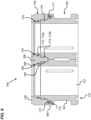
- Fig. 9 shows the springs 171 can be positioned between the flange 169 and the first bearing component 153 for biasing the first bearing component 153 in an inboard direction relative to the second bearing component 155.
- the outer flange 169 can define openings 173 (e.g., axial openings) for allowing outlet pressure from the outer groove 167 to act on the first bearing component 153 thereby forcing the first bearing component 153 in the inboard direction relative to the second bearing component 155 by fluid pressure.
- the openings 173 can be configured for receiving the springs 171 and can include internal spring seats.
- one or more annular seals can be provided between an interior of the first bearing component 153 and an exterior of the second bearing component.
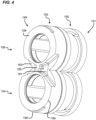
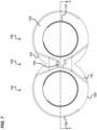
- Figs. 4 , 5 , and 7-10 illustrates the first bearing component 153, engaging with the second bearing component 155.
- the first bearing component 153 defines a first half 154 with one of the through-openings 147, a second half 156 with the other through-opening 147, and an intermediate region 158 partially defined by the both the first and second halves.
- the first bearing component 153 may be a single piece.
- the first bearing component 153 may be divided between the first and second halves 154, 156 into two first bearing components 153 which form a unitary piece when assembled.
- the first bearing component 153 defines a first portion of the through-openings 147 which align with a second portion of the through-openings 147 defined by the second bearing component 155.
- the second bearing component 155 may be inserted into the first bearing component 153 creating a connection interface 175 where an insertion end 176 of the second bearing component 155 may be inserted within a receiving end 178 of the first bearing component 153.
- the insertion end 176 of the through-openings 147 is opposite the outboard end 151 of the second bearing component 155, and the receiving end 178 of the first bearing component 153 is opposite the inboard end 149 of the first bearing component 153.
- the second bearing component 155 defines a space 179 between the insert end 176 defined by the second portion of the two through-openings 147.
- the space 179 allows the intermediate region 158 of the first bearing component 153 to nest between the second portion of the through-openings 147 defined by the second bearing component 155.
- a connection interface 175 is defined between an interior of the through-openings 147 of the first bearing component 153 and the exterior of the insertion end 176 of second bearing component 155.
- the receiving end 178 may positioned adjacent to a outer flange 169 of the second bearing component 155.
- a small gap is present between the receiving end 178 and the outer flange 169 allowing further discharge pressure to move the first bearing component 153 towards the gears 114.
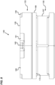
- Fig. 6 , 8 , and 9 illustrates the sealing between first bearing component 153 and the second bearing component 155 of Fig. 1 .
- the connection interface 175 defines annular grooves 172 which allow sealing to occur between the first bearing component 153 and second bearing component 155.
- Each of the annular grooves 172 allow seals 174 to be positioned within the annular grooves 172 for sealing the inlet and discharge pressures created by fluid leakage.
- the annular grooves 172 may be defined within the first bearing component 153.
- the annular grooves 172 may be defined within the second bearing component 155. For instance, in Fig.
- the first bearing component 153 may have a first, second, and third inner circumferential surface 180, 182, 184 which engage with the insertion end 176 of the second bearing component 155 at the connection interface 175.
- the first inner circumferential surface 180 is adjacent to the second axial bearing face 128 of the first bearing component 153.
- the third inner circumferential surface 184 is positioned at the receiving end 178 of the first bearing component and the second inner circumferential surface 182 is positioned between the first and third circumferential surface 180,184.
- the first bearing component 153 may define at least one of the annular grooves 172 for sealing against the inlet and discharge pressure.
- the second inner circumferential surface defines a first seal groove 172a of the two annular grooves 172.
- the exterior of the insertion end 176 may define a second seal groove 172b where the third circumferential surface 184 meets the exterior of through-openings 147 when the first bearing component 153 is inserted over the second bearing component 155.
- each of the two through-openings 147 defined by the second bearing component 155 include a through-opening channel 188 extending from the insertion end 176 to the outboard end 151 of the second bearing component 155.
- an elastomeric seal may additionally be positioned at the outboard end 151 of the second bearing component 155 to seal against the cover 126.
Landscapes
- Engineering & Computer Science (AREA)
- Mechanical Engineering (AREA)
- General Engineering & Computer Science (AREA)
- Rotary Pumps (AREA)
- Details And Applications Of Rotary Liquid Pumps (AREA)
Abstract
Description
- This application claims benefit to
U.S. Provisional Application No. 63/604,637 filed on November 30, 2023 - The invention relates to the technical field of a bearing assembly for supporting gears and sealing against fluid leakage.
- Bearing assemblies are often used in systems such as fuel pumps. For example, journal bearings may be used to support gears within fuel pumps. The journal bearings can be configured to provide some sealing against fluid leakage at the gears. To provide this sealing, a first axial force is applied to movable ones of the journal bearings to press the journal bearings towards the gears relative to the outer housing. An example journal bearing of this type is disclosed by US Patent Publication No.
US2023/0033416 . - The present disclosure relates to a bearing assembly to be used in a fuel pump which may prevent damage caused bearings pressing against gears when the housing or end cap expand with pressure changes. A pump comprises a housing defining a gear chamber. The housing defines an inlet and an outlet in fluid communication with the gear chamber. A gear arrangement is disposed within the gear chamber and is configured to drive fluid from the inlet to the outlet. The gear arrangement includes at least two gears rotatable about corresponding axes of rotation and each of the two gears define first and second axial gear faces that face in opposite axial directions. Journals are coupled to the two gear and are aligned along the axes of the two gears. A first bearing structure includes an inboard end that opposes the first axial gear face of the two gears. Additionally, the first bearing structure defines a first set of through-openings for radially supporting the journals relative to the housing such that the journals are rotatable about the axes of rotation relative to the housing. A second bearing structure includes an inboard end that opposes the second axial gear face of the two gears. The second bearing structure defines a second set of through-openings for radially supporting the journals relative to the housing such that the journals are rotatable about the axes of rotation relative to the housing and the second bearing structure also defines an outboard end. The second bearing structure comprising a first bearing component which defines the inboard end and a second bearing component which defines the outboard end. The first bearing component is axially movable relative to the second bearing component and is configured for directing a first axial force toward the second axial gear face of the two gears. The second bearing component is configured to transfer radial load from the two gears to the housing and to prevent radially load from being applied through the first bearing component. The first bearing component and the second bearing component each define portions of the second set of through-openings.
- A variety of additional inventive aspects will be set forth in the description that follows. The inventive aspects can relate to individual features and to combinations of features. It is to be understood that both the forgoing general description and the following detailed description are exemplary and explanatory only and are not restrictive of the broad inventive concepts upon which the embodiments disclosed herein are based.
-
-
Fig. 1 is a perspective view of a fuel pump in accordance with the principles of the present disclosure; -
Fig. 2 is a transverse cross-section showing a gear chamber and gears of the fuel pump ofFig. 1 ; -
Fig. 3 is an exploded view of the fuel pump ofFig. 1 showing the gears and bearing structures for supporting the gears; -
Fig. 4 is an inboard perspective view of a bearing assembly of the fuel pump ofFig. 1 ; -
Fig. 5 is an outboard perspective view of the bearing assembly ofFig.4 ; -
Fig. 6 is an exploded view of the bearing assembly ofFig.4 ; -
Fig. 7 is an inboard end view of the bearing assembly ofFig. 1 ; -
Fig. 8 is side view of the bearing assembly ofFig. 1 ; -
Fig. 9 is a cross-sectional view of the bearing assembly ofFig. 4 taken along section line 9-9 ofFig. 7 ; and -
Fig. 10 is an outboard end view of the bearing assembly ofFig. 4 . - Certain aspects of the present disclosure relate to a bearing assembly for supporting gears of a gear pump. The bearing assembly can be configured to separate radial bearing functionality and axial sealing functionality into separate bearing components. For example, the bearing assembly can include a first bearing component adapted for providing axial sealing against axial gear faces of the gears and a second bearing component for accommodating radial loading. The first bearing component is axially moveable relative to the second bearing component and is positioned axially between the second bearing component and the axial gear faces. In certain examples, the first bearing component is biased axially toward the axial gear faces and away from the second bearing component. The biasing can be provided by one or more springs and/or by fluid pressure. In certain examples, the second bearing component prevents or limits radial load from being applied to the first bearing component to prevent the first bearing component from being axially locked in place via friction.
- It will be appreciated that during operation of a gear pump such as a fuel gear pump, fluctuations in temperature can cause expansion/contraction of components of the pump. The ability of a bearing component to float or otherwise move relative to the gears prevents excessive axial loading from being applied to the axial end faces of the gears when expansion/contraction occurs. In gear pumps, radial loading of the bearings can cause the bearings to be axially locked in place due to friction which can result in excessive axial loading being applied to the axial gear faces. Aspects of the present disclosure relate to bearing configurations that prevent at least an inboard portion of a bearing from being axially locked by friction so such portion can move to accommodate expansion/contraction of pump components.
-
Figs. 1-3 illustrates a pump 100 (e.g., a fuel pump) in accordance with the principles of the present disclosure. Thepump 100 is adapted to pump fluid (e.g., fuel) from aninlet 102 through agear chamber 118 to anoutlet 104. Theinlet 102, the outlet 104 (shown inFIG. 2 ), and the gear chamber 118 (shown inFIG. 3 ) can be defined by apump housing 116 which may include amain housing body 117 and acover 126. The outlet pressure is significantly higher than the inlet pressure. Agear arrangement 108 is rotationally supported within thepump housing 116 and is configured for pumping fluid through thegear chamber 118 from theinlet 102 to theoutlet 104. It will be appreciated that thepump 100 can include one or more pumping stages, with thegear arrangement 108 corresponding to one of the stages. Further, in some instances, thehousing 116 may definemultiple inlets 102 and/ormultiple outlets 104. - The
gear arrangement 108 includes two intermeshedgears 114 each configured to rotate relative thehousing 116 about acorresponding axis 115. Theaxes 115 are parallel and extend through thegear chamber 118. Thegears 114 are mounted onjournals 120 aligned along theaxes 115. Thegears 114 and thejournals 120 are configured to rotate in unison with each other about theaxes 115. In certain examples, one of thejournals 120 is coupled to a driveshaft that drives rotation of thejournals 120 and theircorresponding gears 114 about theaxes 115. The driveshaft drives one of thegears 114 and thegear 114 driven by the driveshaft drives the other of the two gears. Since only one gear needs to be driven, a single driveshaft can be used. Thegears 114 each include first and second axial gear faces 119, 121 that face in opposite directions. Thejournals 120 are supported for rotation relative to thehousing 116 by afirst bearing structure 122 positioned adjacent the first axial gear faces 119 and asecond bearing structure 123 positioned adjacent the second axial gear faces 121. Thegears 114 can be axially pressed between the first andsecond bearing structures first bearing structure 122 has a firstaxial bearing face 125 that opposes the first axial gear faces 119 and thesecond bearing structure 123 has a secondaxial bearing face 128 that opposes the second axial gear faces 121. - The
first bearing structure 122 includes throughopenings 127 for receiving thejournals 120. The throughopenings 127 can be in fluid communication with theinlet 102 such that the throughopenings 127 are maintained at inlet pressure. The throughopenings 127 can extend axially through thefirst bearing structure 122 from aninboard end 141 to anoutboard end 143. Theinboard end 141 can define the firstaxial bearing face 125. In one example, thefirst bearing structure 122 is rotationally and axially fixed relative to thepump housing 116 and thejournals 120 rotate within the throughopenings 127 relative to thefirst bearing structure 122. The term fixed means axial movement is not intended during use; however, no welding or fastening exists. For instance, thefirst bearing structure 122 may abut against a first stop within thehousing 116 which limits axial movement away from the gears. Because the inlet pressure and discharge pressure may be different, an uneven radial load may be asserted on the gears. The radial load can be greatest in one radial direction as a result of the difference in pressure between theinlet 102 and theoutlet 104. The radial load is then transferred from thegears 114 to thejournals 120 and from thejournals 120 through thefirst bearing structure 122 to thepump housing 116. Thefirst bearing structure 122 can definecircumferential grooves 129 about theaxes 115 at peripheral portions of theinboard end 141. Thecircumferential grooves 129 are in fluid communication with theoutlet 104 and can be configured to enhance the application of outlet pressure at the firstaxial bearing face 125. Thefirst bearing structure 122 can define aninlet region 131 corresponding to theinlet 102 and anoutlet region 133 corresponding to theoutlet 104. The inlet andoutlet regions axial bearing face 125 and can be separated by adivider 165. - The
second bearing structure 123 includes through-openings 147 for receiving thejournals 120. The through-openings 147 can be in fluid communication with theinlet 102 such that the through-openings 147 are maintained at inlet pressure. Thesecond bearing structure 123 defines aninboard end 149 and anoutboard end 151. Theinboard end 149 defines the secondaxial bearing face 128. The through-openings 147 extend axially through thesecond bearing structure 123 from theinboard end 149 to theoutboard end 151. In one example, thesecond bearing structure 123 has a multi-part construction with different bearing components being designed to provide different bearing functionality. For example, thesecond bearing structure 123 can include afirst bearing component 153 that defines theinboard end 149 and asecond bearing component 155 that defines theoutboard end 151. Thefirst bearing component 153 can include the secondaxial bearing face 128 can be configured for applying an axial sealing force toward the second axial gear faces 121 for causing the first and second axial gear faces 119, 121 to be pressed axially between the first and second axial bearing faces 125, 127 of the first andsecond bearing structures axial bearing face 128. The axial sealing force helps pressurize the fluid and maintain a minimal gap between the secondaxial gear face 121, and the secondaxial bearing face 128. Thefirst bearing component 153 is preferably positioned axially between thesecond bearing component 155 and the secondaxial gear face 121 and is preferably axially moveable relative to thesecond bearing component 155 and relative to thehousing 116 and thegears 114. In some examples, thefirst bearing component 153 can be forced axially away from thesecond bearing component 155 and axially toward the gears 114 (e.g., by a spring force generated by one or more springs and/or by fluid pressure). Thesecond bearing component 155 can be configured to transfer radial load to thepump housing 116. In certain examples, thesecond bearing component 155 is rotationally and axially fixed relative to thepump housing 116 and thejournals 120 rotate within the through-openings 147 relative to both the first andsecond bearing components second bearing structure 123 may abut against thecover 126 such that thecover 126 acts as an axial stop, and sealing can be provided between theoutboard end 151 of thesecond bearing component 155 and thecover 126. The through-openings 147 are defined at least partially by each of the first and second bearing components 153,155. The radial load applied through thesecond bearing component 155 can be greatest in one radial direction as a result of the difference in pressure between theinlet 102 and theoutlet 104. The first andsecond bearing components second bearing component 155 limits or eliminates radial load that is applied through thefirst bearing component 153 thereby preventing thefirst bearing component 153 from being frictionally axially held in place with respect to thehousing 116 in a way that would inhibit effective axial movement of thefirst bearing component 153. In certain examples, thesecond bearing component 155 is larger in a radial dimension than thefirst bearing component 153 or is otherwise configured to reduce, limit or prevent radial contact between the first bearing component and thepump housing 116. - It will be appreciated that the
first bearing component 153 is configured to float or otherwise move axially relative to thesecond bearing component 155 to provide hydraulic face sealing against the gears 114 (e.g., a pressurized layer of fluid can be provided between the gears and the inboard ends of the first and second bearing structures 122,123). Thefirst bearing component 153 is preferably urged in an inboard direction toward thegears 114 and away from thesecond bearing component 155. The urging of thefirst bearing component 153 forces theoutboard end 151 of thesecond bearing component 155 against thecover 126 and also urges theoutboard end 143 of thefirst bearing structure 122 against the axial stop within thehousing 116. In this way, thefirst bearing structure 122 and thesecond bearing component 155 are maintained at a fixed axial position during use. - As shown in
Fig. 6-9 , thefirst bearing structure 153 can definecircumferential grooves 159 about theaxes 115 at peripheral portions of the second axial bearing face 128 (e.g., at the inboard end 149). Thecircumferential grooves 159 are in fluid communication with theoutlet 104 and can be configured to enhance the application of outlet pressure at the secondaxial bearing face 128. Thefirst bearing component 153 can define aninlet region 161 corresponding to theinlet 102 and anoutlet region 163 corresponding to theoutlet 104. The inlet andoutlet regions inboard end 149 and can be separated by adivider 165. The inlet andoutlet regions first bearing component 153 can align and be in fluid communication with the inlet andoutlet regions first bearing structure 122. Atransitional region 160 is positioned between theinlet region 161 and thecircumferential groove 159. Thesecond bearing component 155 may be two separated halves which form a unitary piece when assembled. In other instances, thesecond bearing component 155 may be a single piece. - As shown in
Figs. 5 ,6 ,8 , and9 , thesecond bearing component 155 is depicted including anouter groove 167 that preferably is in fluid communication with theoutlet 104. Theouter groove 167 is defined in part by anouter flange 169.Fig. 9 shows thesprings 171 can be positioned between theflange 169 and thefirst bearing component 153 for biasing thefirst bearing component 153 in an inboard direction relative to thesecond bearing component 155. Theouter flange 169 can define openings 173 (e.g., axial openings) for allowing outlet pressure from theouter groove 167 to act on thefirst bearing component 153 thereby forcing thefirst bearing component 153 in the inboard direction relative to thesecond bearing component 155 by fluid pressure. In one example, theopenings 173 can be configured for receiving thesprings 171 and can include internal spring seats. In on example, one or more annular seals can be provided between an interior of thefirst bearing component 153 and an exterior of the second bearing component. -
Figs. 4 ,5 , and7-10 illustrates thefirst bearing component 153, engaging with thesecond bearing component 155. Thefirst bearing component 153 defines afirst half 154 with one of the through-openings 147, asecond half 156 with the other through-opening 147, and anintermediate region 158 partially defined by the both the first and second halves. In some examples, thefirst bearing component 153 may be a single piece. In other examples, thefirst bearing component 153 may be divided between the first andsecond halves first bearing components 153 which form a unitary piece when assembled. Thefirst bearing component 153 defines a first portion of the through-openings 147 which align with a second portion of the through-openings 147 defined by thesecond bearing component 155. - As shown in
Fig. 6 ,8 , and9 , thesecond bearing component 155 may be inserted into thefirst bearing component 153 creating aconnection interface 175 where aninsertion end 176 of thesecond bearing component 155 may be inserted within a receivingend 178 of thefirst bearing component 153. Theinsertion end 176 of the through-openings 147 is opposite theoutboard end 151 of thesecond bearing component 155, and the receivingend 178 of thefirst bearing component 153 is opposite theinboard end 149 of thefirst bearing component 153. Thesecond bearing component 155 defines aspace 179 between theinsert end 176 defined by the second portion of the two through-openings 147. Thespace 179 allows theintermediate region 158 of thefirst bearing component 153 to nest between the second portion of the through-openings 147 defined by thesecond bearing component 155. Aconnection interface 175 is defined between an interior of the through-openings 147 of thefirst bearing component 153 and the exterior of theinsertion end 176 ofsecond bearing component 155. As shown inFigs. 8 and9 , when theinsertion end 176 is inserted into the receivingend 178 of thefirst bearing component 153, the receivingend 178 may positioned adjacent to aouter flange 169 of thesecond bearing component 155. A small gap is present between the receivingend 178 and theouter flange 169 allowing further discharge pressure to move thefirst bearing component 153 towards thegears 114. -
Fig. 6 ,8 , and9 illustrates the sealing betweenfirst bearing component 153 and thesecond bearing component 155 ofFig. 1 . Theconnection interface 175 defines annular grooves 172 which allow sealing to occur between thefirst bearing component 153 andsecond bearing component 155. Each of the annular grooves 172 allowseals 174 to be positioned within the annular grooves 172 for sealing the inlet and discharge pressures created by fluid leakage. In some instances, the annular grooves 172 may be defined within thefirst bearing component 153. In other instances, the annular grooves 172 may be defined within thesecond bearing component 155. For instance, inFig. 9 , thefirst bearing component 153 may have a first, second, and third innercircumferential surface insertion end 176 of thesecond bearing component 155 at theconnection interface 175. The first innercircumferential surface 180 is adjacent to the secondaxial bearing face 128 of thefirst bearing component 153. The third innercircumferential surface 184 is positioned at the receivingend 178 of the first bearing component and the second innercircumferential surface 182 is positioned between the first and third circumferential surface 180,184. Thefirst bearing component 153 may define at least one of the annular grooves 172 for sealing against the inlet and discharge pressure. InFig. 9 of the embodiment ofFig. 1 , the second inner circumferential surface defines a first seal groove 172a of the two annular grooves 172. The exterior of theinsertion end 176 may define a second seal groove 172b where the thirdcircumferential surface 184 meets the exterior of through-openings 147 when thefirst bearing component 153 is inserted over thesecond bearing component 155. Further, each of the two through-openings 147 defined by thesecond bearing component 155 include a through-openingchannel 188 extending from theinsertion end 176 to theoutboard end 151 of thesecond bearing component 155. In some examples, an elastomeric seal may additionally be positioned at theoutboard end 151 of thesecond bearing component 155 to seal against thecover 126. - The various examples described above are provided by way of illustration only and should not be construed to limit the scope of the present disclosure. Those skilled in the art will readily recognize various modifications and changes that may be made without following the examples and applications illustrated and described herein, and without departing from the true spirit and scope of the present disclosure.
-
- 1. A pump comprising:
- a housing defining a gear chamber, the housing defining an inlet and an outlet in fluid communication with the gear chamber;
- a gear arrangement disposed within the gear chamber configured to drive fluid from the inlet to the outlet, the gear arrangement including at least two gears rotatable about corresponding axes of rotation, each of the two gears defining first and second axial gear faces that face in opposite axial directions;
- journals coupled to the two gears and aligned along the axes of the two gears;
- a first bearing structure including an inboard end that opposes the first axial gear face of the two gears, the first bearing structure defining a first set of through-openings for radially supporting the journals relative to the housing such that the journals are rotatable about the axes of rotation relative to the housing;
- a second bearing structure including an inboard end that opposes the second axial gear face of the two gears, the second bearing structure defining a second set of through-openings for radially supporting the journals relative to the housing such that the journals are rotatable about the axes of rotation relative to the housing, the second bearing structure also defining an outboard end; and
- the second bearing structure comprising a first bearing component defining the inboard end and a second bearing component defining the outboard end, the first bearing component being axially movable relative to the second bearing component and being configured for directing a first axial force toward the second axial gear face of the two gears, the second bearing component being configured to transfer radial load from the two gears to the housing and for preventing radially load from being applied through the first bearing component, the first bearing component and the second bearing component each defining portions of the second set of through-openings.
- 2. The pump of aspect 1, wherein fluid pressure from the outlet is used to force the first bearing component in an inboard direction away from the second bearing component and towards the two gears.
- 3. The pump of aspect 1 or 2, wherein springs are used to bias the first bearing component in an inboard direction away from the second bearing component and towards the two gears.
- 4. The pump of aspects 1-3, wherein fluid pressure from the outlet and springs are used to force the first bearing component in the inboard direction away from the second bearing component and towards the two gears.
- 5. The pump of aspects 1-4, wherein the second bearing component defines a flange with a plurality of openings, the flange abutting the first bearing, the plurality of openings allowing springs and/or fluid pressures to direct the first bearing component in an inboard direction towards the two gears.
- 6. The pump of aspects 1-5, wherein the second bearing component may have an outer groove defined partially by the flange.
- 7. The pump of aspects 1-6, wherein the outer groove is in fluid communication with the outlet.
- 8. The pump of aspects 1-7, a second axial bearing face of the first bearing component includes an inlet region in fluid communication with the inlet and an outlet region in fluid communication with the outlet.
- 9. The pump of aspects 1-8, the second axial bearing face further includes a circumferential groove around the second axial bearing face and joining with the outlet region.
- 10. The pump of aspects 1-9, wherein the inlet region and the outlet region may be separated by a divider.
- 11. The pump of aspects 1-10, wherein the first bearing component may define a first half and a second half, wherein each half includes one through-opening of the second set of through-openings.
- 12. The pump of aspects 1-11, wherein the first bearing component may be a two-piece configuration wherein each of the first and second half may be separate pieces joined together.
- 13. The pump of aspects 1-12, wherein axial movement of the first bearing structure is fixed.
- 14. The pump of aspects 1-13, wherein axial movement of the second bearing component is fixed
- 15. The pump of aspects 1-14, wherein axial movement of the second bearing component is fixed, and axial movement of the first bearing structure is fixed.
- 16. The pump of aspects 1-15, wherein the first bearing component includes an intermediate portion between the first half and second half, which nests between the portions of the second set of through-openings defined by the second bearing component.
Claims (15)
- A pump comprising:a housing defining a gear chamber, the housing defining an inlet and an outlet in fluid communication with the gear chamber;a gear arrangement disposed within the gear chamber configured to drive fluid from the inlet to the outlet, the gear arrangement including at least two gears rotatable about corresponding axes of rotation, each of the two gears defining first and second axial gear faces that face in opposite axial directions;journals coupled to the two gears and aligned along the axes of the two gears;a first bearing structure including an inboard end that opposes the first axial gear face of the two gears, the first bearing structure defining a first set of through-openings for radially supporting the journals relative to the housing such that the journals are rotatable about the axes of rotation relative to the housing;a second bearing structure including an inboard end that opposes the second axial gear face of the two gears, the second bearing structure defining a second set of through-openings for radially supporting the journals relative to the housing such that the journals are rotatable about the axes of rotation relative to the housing, the second bearing structure also defining an outboard end; andthe second bearing structure comprising a first bearing component defining the inboard end and a second bearing component defining the outboard end, the first bearing component being axially movable relative to the second bearing component and being configured for directing a first axial force toward the second axial gear face of the two gears, the second bearing component being configured to transfer radial load from the two gears to the housing and for preventing radially load from being applied through the first bearing component, the first bearing component and the second bearing component each defining portions of the second set of through-openings.
- The pump of claim 1, wherein fluid pressure from the outlet is used to force the first bearing component in an inboard direction away from the second bearing component and towards the two gears.
- The pump of claim 1 or claim 2, wherein springs are used to bias the first bearing component in an inboard direction away from the second bearing component and towards the two gears.
- The pump of claim 3, wherein fluid pressure from the outlet and springs are used to force the first bearing component in the inboard direction away from the second bearing component and towards the two gears.
- The pump of any preceding claim, wherein the second bearing component defines a flange with a plurality of openings, the flange abutting the first bearing component, the plurality of openings allowing springs and/or fluid pressures to direct the first bearing component in an inboard direction towards the two gears.
- The pump of claim 5, wherein the second bearing component may have an outer groove defined partially by the flange.
- The pump of claim 6, wherein the outer groove is in fluid communication with the outlet.
- The pump of any preceding claim, a second axial bearing face of the first bearing component includes an inlet region in fluid communication with the inlet and an outlet region in fluid communication with the outlet.
- The pump of claim 8, the second axial bearing face further includes a circumferential groove around the second axial bearing face and joining with the outlet region.
- The pump of claim 8 or claim 9, wherein the inlet region and the outlet region may be separated by a divider.
- The pump of any preceding claim, wherein the first bearing component may define a first half and a second half, wherein each half includes one through-opening of the second set of through-openings.
- The pump of any preceding claim, wherein the first bearing component may be a two-piece configuration wherein each of the first and second half may be separate pieces joined together.
- The pump of any preceding claim, wherein axial movement of the first bearing structure is fixed.
- The pump of any preceding claim, wherein axial movement of the second bearing component is fixed
- The pump of any of claims 12 to 14, wherein the first bearing component includes an intermediate portion between the first half and second half, which nests between the portions of the second set of through-openings defined by the second bearing component.
Applications Claiming Priority (1)
| Application Number | Priority Date | Filing Date | Title |
|---|---|---|---|
| US202363604637P | 2023-11-30 | 2023-11-30 |
Publications (1)
| Publication Number | Publication Date |
|---|---|
| EP4563821A1 true EP4563821A1 (en) | 2025-06-04 |
Family
ID=93741450
Family Applications (1)
| Application Number | Title | Priority Date | Filing Date |
|---|---|---|---|
| EP24216108.1A Pending EP4563821A1 (en) | 2023-11-30 | 2024-11-28 | Bearing for pump |
Country Status (2)
| Country | Link |
|---|---|
| US (1) | US20250180016A1 (en) |
| EP (1) | EP4563821A1 (en) |
Citations (6)
| Publication number | Priority date | Publication date | Assignee | Title |
|---|---|---|---|---|
| US2527941A (en) * | 1948-05-22 | 1950-10-31 | Borg Warner | Pump-multiple piece bushing |
| US2728301A (en) * | 1952-06-17 | 1955-12-27 | Lindberg Trust | Gear pump |
| GB1121101A (en) * | 1964-08-08 | 1968-07-24 | Bosch Gmbh Robert | Improvements in rotary pumps and motors |
| DE102007051352A1 (en) * | 2007-10-26 | 2009-04-30 | Robert Bosch Gmbh | Hydraulic gear wheel machine i.e. external gear wheel machine such as external gear wheel motor, for generating and converting of hydraulic energy, has actuators adjusting opening independent of operating pressure during machine operation |
| US20120156080A1 (en) * | 2009-03-12 | 2012-06-21 | Robert Bosch Gmbh | Hydraulic Toothed Wheel Machine |
| US20230033416A1 (en) | 2021-07-27 | 2023-02-02 | Eaton Intelligent Power Limited | Controlling pressure on a journal bearing |
Family Cites Families (2)
| Publication number | Priority date | Publication date | Assignee | Title |
|---|---|---|---|---|
| US3528756A (en) * | 1968-12-04 | 1970-09-15 | Borg Warner | Pressure loaded pump |
| US9890813B2 (en) * | 2014-11-03 | 2018-02-13 | Hamilton Sundstrand Corporation | Gear pump bearings with hybrid pads |
-
2024
- 2024-11-26 US US18/960,525 patent/US20250180016A1/en active Pending
- 2024-11-28 EP EP24216108.1A patent/EP4563821A1/en active Pending
Patent Citations (6)
| Publication number | Priority date | Publication date | Assignee | Title |
|---|---|---|---|---|
| US2527941A (en) * | 1948-05-22 | 1950-10-31 | Borg Warner | Pump-multiple piece bushing |
| US2728301A (en) * | 1952-06-17 | 1955-12-27 | Lindberg Trust | Gear pump |
| GB1121101A (en) * | 1964-08-08 | 1968-07-24 | Bosch Gmbh Robert | Improvements in rotary pumps and motors |
| DE102007051352A1 (en) * | 2007-10-26 | 2009-04-30 | Robert Bosch Gmbh | Hydraulic gear wheel machine i.e. external gear wheel machine such as external gear wheel motor, for generating and converting of hydraulic energy, has actuators adjusting opening independent of operating pressure during machine operation |
| US20120156080A1 (en) * | 2009-03-12 | 2012-06-21 | Robert Bosch Gmbh | Hydraulic Toothed Wheel Machine |
| US20230033416A1 (en) | 2021-07-27 | 2023-02-02 | Eaton Intelligent Power Limited | Controlling pressure on a journal bearing |
Also Published As
| Publication number | Publication date |
|---|---|
| US20250180016A1 (en) | 2025-06-05 |
Similar Documents
| Publication | Publication Date | Title |
|---|---|---|
| EP1479951B1 (en) | Shaft seal | |
| CN104246324B (en) | The straight-flanked ring of interior tensioning | |
| US4225112A (en) | Butterfly valve with a retaining ring | |
| CN105745452B (en) | unloading mechanism | |
| US4274298A (en) | Drive unit seal assembly | |
| EP3321547B1 (en) | Seal assembly for a rotating member | |
| EP4563821A1 (en) | Bearing for pump | |
| US4225113A (en) | Butterfly valve having cartridge construction with improved bearings | |
| JPH11182462A (en) | Scroll compressor | |
| US10487844B2 (en) | Mechanical seal for rotating shaft | |
| JPS62142881A (en) | Gear type pump | |
| EP3449129B1 (en) | Modular thrust-compensating rotor assembly | |
| US12535077B2 (en) | Electric compressor | |
| JPWO2021117335A5 (en) | ||
| CN113847240B (en) | Pump comprising an axially acting spring washer | |
| EP0010357B1 (en) | Butterfly valve | |
| CN114623077A (en) | bead liner | |
| US20030015843A1 (en) | High speed high pressure rotary | |
| EP3715634B1 (en) | Gear pump bearing with hybrid pad shutoff | |
| US12392411B2 (en) | Seal arrangement with low drag seal gland | |
| CN223609306U (en) | Mechanical seal for high-pressure lubricating oil rotor pump | |
| CN113994095A (en) | Variable displacement lubricant pump | |
| EP4155566B1 (en) | Integrated seal and bearing assembly and method of forming an integrated seal and bearing assembly | |
| US12117083B2 (en) | Sealing assemblies for sealing between rotating and non-rotating components | |
| US11518189B2 (en) | Hub structure |
Legal Events
| Date | Code | Title | Description |
|---|---|---|---|
| PUAI | Public reference made under article 153(3) epc to a published international application that has entered the european phase |
Free format text: ORIGINAL CODE: 0009012 |
|
| STAA | Information on the status of an ep patent application or granted ep patent |
Free format text: STATUS: THE APPLICATION HAS BEEN PUBLISHED |
|
| AK | Designated contracting states |
Kind code of ref document: A1 Designated state(s): AL AT BE BG CH CY CZ DE DK EE ES FI FR GB GR HR HU IE IS IT LI LT LU LV MC ME MK MT NL NO PL PT RO RS SE SI SK SM TR |
|
| STAA | Information on the status of an ep patent application or granted ep patent |
Free format text: STATUS: REQUEST FOR EXAMINATION WAS MADE |
|
| 17P | Request for examination filed |
Effective date: 20250930 |
|
| STAA | Information on the status of an ep patent application or granted ep patent |
Free format text: STATUS: EXAMINATION IS IN PROGRESS |
|
| 17Q | First examination report despatched |
Effective date: 20260105 |