EP4563808A1 - Veicolo, in particolare imbarcazione, con un sistema di conversione di energia per generare una pressione idraulica - Google Patents
Veicolo, in particolare imbarcazione, con un sistema di conversione di energia per generare una pressione idraulica Download PDFInfo
- Publication number
- EP4563808A1 EP4563808A1 EP24215012.6A EP24215012A EP4563808A1 EP 4563808 A1 EP4563808 A1 EP 4563808A1 EP 24215012 A EP24215012 A EP 24215012A EP 4563808 A1 EP4563808 A1 EP 4563808A1
- Authority
- EP
- European Patent Office
- Prior art keywords
- barrel
- vehicle according
- pressure branch
- piston
- rod
- Prior art date
- Legal status (The legal status is an assumption and is not a legal conclusion. Google has not performed a legal analysis and makes no representation as to the accuracy of the status listed.)
- Pending
Links
Images


Classifications
-
- F—MECHANICAL ENGINEERING; LIGHTING; HEATING; WEAPONS; BLASTING
- F15—FLUID-PRESSURE ACTUATORS; HYDRAULICS OR PNEUMATICS IN GENERAL
- F15B—SYSTEMS ACTING BY MEANS OF FLUIDS IN GENERAL; FLUID-PRESSURE ACTUATORS, e.g. SERVOMOTORS; DETAILS OF FLUID-PRESSURE SYSTEMS, NOT OTHERWISE PROVIDED FOR
- F15B11/00—Servomotor systems without provision for follow-up action; Circuits therefor
- F15B11/08—Servomotor systems without provision for follow-up action; Circuits therefor with only one servomotor
- F15B11/12—Servomotor systems without provision for follow-up action; Circuits therefor with only one servomotor providing distinct intermediate positions; with step-by-step action
- F15B11/121—Servomotor systems without provision for follow-up action; Circuits therefor with only one servomotor providing distinct intermediate positions; with step-by-step action providing distinct intermediate positions
-
- F—MECHANICAL ENGINEERING; LIGHTING; HEATING; WEAPONS; BLASTING
- F03—MACHINES OR ENGINES FOR LIQUIDS; WIND, SPRING, OR WEIGHT MOTORS; PRODUCING MECHANICAL POWER OR A REACTIVE PROPULSIVE THRUST, NOT OTHERWISE PROVIDED FOR
- F03B—MACHINES OR ENGINES FOR LIQUIDS
- F03B13/00—Adaptations of machines or engines for special use; Combinations of machines or engines with driving or driven apparatus; Power stations or aggregates
- F03B13/12—Adaptations of machines or engines for special use; Combinations of machines or engines with driving or driven apparatus; Power stations or aggregates characterised by using wave or tide energy
- F03B13/14—Adaptations of machines or engines for special use; Combinations of machines or engines with driving or driven apparatus; Power stations or aggregates characterised by using wave or tide energy using wave energy
- F03B13/16—Adaptations of machines or engines for special use; Combinations of machines or engines with driving or driven apparatus; Power stations or aggregates characterised by using wave or tide energy using wave energy using the relative movement between a wave-operated member, i.e. a "wom" and another member, i.e. a reaction member or "rem"
- F03B13/18—Adaptations of machines or engines for special use; Combinations of machines or engines with driving or driven apparatus; Power stations or aggregates characterised by using wave or tide energy using wave energy using the relative movement between a wave-operated member, i.e. a "wom" and another member, i.e. a reaction member or "rem" where the other member, i.e. rem is fixed, at least at one point, with respect to the sea bed or shore
- F03B13/1845—Adaptations of machines or engines for special use; Combinations of machines or engines with driving or driven apparatus; Power stations or aggregates characterised by using wave or tide energy using wave energy using the relative movement between a wave-operated member, i.e. a "wom" and another member, i.e. a reaction member or "rem" where the other member, i.e. rem is fixed, at least at one point, with respect to the sea bed or shore and the wom slides relative to the rem
- F03B13/187—Adaptations of machines or engines for special use; Combinations of machines or engines with driving or driven apparatus; Power stations or aggregates characterised by using wave or tide energy using wave energy using the relative movement between a wave-operated member, i.e. a "wom" and another member, i.e. a reaction member or "rem" where the other member, i.e. rem is fixed, at least at one point, with respect to the sea bed or shore and the wom slides relative to the rem and the wom directly actuates the piston of a pump
-
- F—MECHANICAL ENGINEERING; LIGHTING; HEATING; WEAPONS; BLASTING
- F03—MACHINES OR ENGINES FOR LIQUIDS; WIND, SPRING, OR WEIGHT MOTORS; PRODUCING MECHANICAL POWER OR A REACTIVE PROPULSIVE THRUST, NOT OTHERWISE PROVIDED FOR
- F03B—MACHINES OR ENGINES FOR LIQUIDS
- F03B13/00—Adaptations of machines or engines for special use; Combinations of machines or engines with driving or driven apparatus; Power stations or aggregates
- F03B13/12—Adaptations of machines or engines for special use; Combinations of machines or engines with driving or driven apparatus; Power stations or aggregates characterised by using wave or tide energy
- F03B13/14—Adaptations of machines or engines for special use; Combinations of machines or engines with driving or driven apparatus; Power stations or aggregates characterised by using wave or tide energy using wave energy
- F03B13/16—Adaptations of machines or engines for special use; Combinations of machines or engines with driving or driven apparatus; Power stations or aggregates characterised by using wave or tide energy using wave energy using the relative movement between a wave-operated member, i.e. a "wom" and another member, i.e. a reaction member or "rem"
- F03B13/20—Adaptations of machines or engines for special use; Combinations of machines or engines with driving or driven apparatus; Power stations or aggregates characterised by using wave or tide energy using wave energy using the relative movement between a wave-operated member, i.e. a "wom" and another member, i.e. a reaction member or "rem" wherein both members, i.e. wom and rem are movable relative to the sea bed or shore
-
- F—MECHANICAL ENGINEERING; LIGHTING; HEATING; WEAPONS; BLASTING
- F15—FLUID-PRESSURE ACTUATORS; HYDRAULICS OR PNEUMATICS IN GENERAL
- F15B—SYSTEMS ACTING BY MEANS OF FLUIDS IN GENERAL; FLUID-PRESSURE ACTUATORS, e.g. SERVOMOTORS; DETAILS OF FLUID-PRESSURE SYSTEMS, NOT OTHERWISE PROVIDED FOR
- F15B15/00—Fluid-actuated devices for displacing a member from one position to another; Gearing associated therewith
- F15B15/08—Characterised by the construction of the motor unit
- F15B15/14—Characterised by the construction of the motor unit of the straight-cylinder type
- F15B15/1409—Characterised by the construction of the motor unit of the straight-cylinder type with two or more independently movable working pistons
-
- F—MECHANICAL ENGINEERING; LIGHTING; HEATING; WEAPONS; BLASTING
- F15—FLUID-PRESSURE ACTUATORS; HYDRAULICS OR PNEUMATICS IN GENERAL
- F15B—SYSTEMS ACTING BY MEANS OF FLUIDS IN GENERAL; FLUID-PRESSURE ACTUATORS, e.g. SERVOMOTORS; DETAILS OF FLUID-PRESSURE SYSTEMS, NOT OTHERWISE PROVIDED FOR
- F15B15/00—Fluid-actuated devices for displacing a member from one position to another; Gearing associated therewith
- F15B15/08—Characterised by the construction of the motor unit
- F15B15/14—Characterised by the construction of the motor unit of the straight-cylinder type
- F15B15/149—Fluid interconnections, e.g. fluid connectors, passages
-
- F—MECHANICAL ENGINEERING; LIGHTING; HEATING; WEAPONS; BLASTING
- F15—FLUID-PRESSURE ACTUATORS; HYDRAULICS OR PNEUMATICS IN GENERAL
- F15B—SYSTEMS ACTING BY MEANS OF FLUIDS IN GENERAL; FLUID-PRESSURE ACTUATORS, e.g. SERVOMOTORS; DETAILS OF FLUID-PRESSURE SYSTEMS, NOT OTHERWISE PROVIDED FOR
- F15B21/00—Common features of fluid actuator systems; Fluid-pressure actuator systems or details thereof, not covered by any other group of this subclass
- F15B21/14—Energy-recuperation means
-
- F—MECHANICAL ENGINEERING; LIGHTING; HEATING; WEAPONS; BLASTING
- F05—INDEXING SCHEMES RELATING TO ENGINES OR PUMPS IN VARIOUS SUBCLASSES OF CLASSES F01-F04
- F05B—INDEXING SCHEME RELATING TO WIND, SPRING, WEIGHT, INERTIA OR LIKE MOTORS, TO MACHINES OR ENGINES FOR LIQUIDS COVERED BY SUBCLASSES F03B, F03D AND F03G
- F05B2240/00—Components
- F05B2240/90—Mounting on supporting structures or systems
- F05B2240/93—Mounting on supporting structures or systems on a structure floating on a liquid surface
- F05B2240/931—Mounting on supporting structures or systems on a structure floating on a liquid surface which is a vehicle
-
- F—MECHANICAL ENGINEERING; LIGHTING; HEATING; WEAPONS; BLASTING
- F05—INDEXING SCHEMES RELATING TO ENGINES OR PUMPS IN VARIOUS SUBCLASSES OF CLASSES F01-F04
- F05B—INDEXING SCHEME RELATING TO WIND, SPRING, WEIGHT, INERTIA OR LIKE MOTORS, TO MACHINES OR ENGINES FOR LIQUIDS COVERED BY SUBCLASSES F03B, F03D AND F03G
- F05B2260/00—Function
- F05B2260/40—Transmission of power
- F05B2260/406—Transmission of power through hydraulic systems
-
- F—MECHANICAL ENGINEERING; LIGHTING; HEATING; WEAPONS; BLASTING
- F15—FLUID-PRESSURE ACTUATORS; HYDRAULICS OR PNEUMATICS IN GENERAL
- F15B—SYSTEMS ACTING BY MEANS OF FLUIDS IN GENERAL; FLUID-PRESSURE ACTUATORS, e.g. SERVOMOTORS; DETAILS OF FLUID-PRESSURE SYSTEMS, NOT OTHERWISE PROVIDED FOR
- F15B2211/00—Circuits for servomotor systems
- F15B2211/30—Directional control
- F15B2211/305—Directional control characterised by the type of valves
- F15B2211/30505—Non-return valves, i.e. check valves
-
- F—MECHANICAL ENGINEERING; LIGHTING; HEATING; WEAPONS; BLASTING
- F15—FLUID-PRESSURE ACTUATORS; HYDRAULICS OR PNEUMATICS IN GENERAL
- F15B—SYSTEMS ACTING BY MEANS OF FLUIDS IN GENERAL; FLUID-PRESSURE ACTUATORS, e.g. SERVOMOTORS; DETAILS OF FLUID-PRESSURE SYSTEMS, NOT OTHERWISE PROVIDED FOR
- F15B2211/00—Circuits for servomotor systems
- F15B2211/60—Circuit components or control therefor
- F15B2211/625—Accumulators
-
- F—MECHANICAL ENGINEERING; LIGHTING; HEATING; WEAPONS; BLASTING
- F15—FLUID-PRESSURE ACTUATORS; HYDRAULICS OR PNEUMATICS IN GENERAL
- F15B—SYSTEMS ACTING BY MEANS OF FLUIDS IN GENERAL; FLUID-PRESSURE ACTUATORS, e.g. SERVOMOTORS; DETAILS OF FLUID-PRESSURE SYSTEMS, NOT OTHERWISE PROVIDED FOR
- F15B2211/00—Circuits for servomotor systems
- F15B2211/70—Output members, e.g. hydraulic motors or cylinders or control therefor
- F15B2211/705—Output members, e.g. hydraulic motors or cylinders or control therefor characterised by the type of output members or actuators
- F15B2211/7051—Linear output members
- F15B2211/7053—Double-acting output members
- F15B2211/7054—Having equal piston areas
Definitions
- the invention relates to a vehicle provided with an energy conversion system for generating a hydraulic pressure, starting from an oscillatory movement or a vibration of a vehicle component.
- the energy conversion system of the present invention exploits external loads of variable magnitude which are normally present during the navigation of a boat (such as inertial accelerations due to the wave motion of the sea, the wind acting on sails under tension, variable loads due to water acting on immersed members, etc.).
- hydraulic pressure requires a pump powered by electrical energy, which is generally produced by motion of an internal combustion engine, also arranged on board and supplied, in turn, with fossil fuels.
- This configuration involves some drawbacks, including: the emission of pollutants produced by the combustion of fossil fuel, the weight of the fuel on board, and the sizing of the tanks for containing such fuel.
- the need is felt to limit the aforesaid drawbacks by exploiting alternative energy sources.
- the need is felt to exploit forces or accelerations which are normally present during the journey and generate an oscillatory or vibratory motion on one or more components of the vehicle.
- the need is felt to exploit such forces/accelerations to generate a hydraulic pressure, which will replace or supplement the one provided by the electric pump, thus limiting the energy consumed by such a pump.
- the object of the present invention is thus to meet the need described above, preferably in a simple and/or reliable and/or effective manner.
- the object is achieved by a vehicle, in particular a boat, with an energy conversion system according to claim 1.
- reference numeral 1 is used to indicate, as a whole, a boat (partially and schematically illustrated), in particular a sail boat.
- the boat 1 comprises a hydraulic system 5, of known type and schematically illustrated, for feeding oil under pressure to a plurality of hydraulic users (which include, for example, at least one hydraulic cylinder 21).
- the boat further comprises a plurality of components 10 which are subjected, during navigation, to forces or accelerations suitable to cause an oscillatory or vibratory motion on the same components 10.
- forces or accelerations can be defined by external loads of variable magnitude due, for example, to normal changes in wind speed and direction, wave motion, normal variations in water thrust on parts immersed in water, or aerodynamic loads on the sails, etc.
- the components 10 are defined by movable members coupled to respective actuators 20, which are operated to keep such components 10 in a predefined position.
- the actuators 20 can be defined by:
- the components 10 are arranged in a predefined position and are constrained to a fixed structure 30 of the boat 1, and thus are not operated by an actuator, but are naturally provided with an oscillation or a vibration due to variable external loads.
- the components 10 are defined by masses which are coupled to the fixed structure 30 so as to move substantially freely and are subject to natural inertial forces, due to wave motion and/or the consequent rocking of the boat, whereby they have an oscillatory motion of an inertial nature.
- the components 10 potentially having vibratory or oscillatory motion during navigation may be of a different type with respect to those mentioned above, and are known to the person skilled in the art, whereby they are not listed in detail here for the sake of brevity.
- the boat 1 comprises an energy conversion system 100 configured so as to recover energy which is naturally associated with the aforesaid oscillations/vibrations, and thus convert this energy into a hydraulic pressure, which can be transferred to the hydraulic system 5 and used in the latter (for example to operate the hydraulic cylinders 21).
- the energy conversion system 100 comprises a hydraulic circuit 101 connected to the hydraulic system 5.
- the hydraulic circuit 101 comprises a high pressure branch 102 and a low pressure branch 103, respectively connected to a delivery branch 104 and to a return branch 105 of the hydraulic system 5, by one or more valves 106.
- the hydraulic circuit 101 further comprises a high pressure accumulator 108, of known type and not described in detail, arranged along the high pressure branch 102 and configured so as to receive and accumulate oil under pressure, and thus feed the accumulated oil towards the delivery branch 104 (opening the valves 106). More preferably, the hydraulic circuit 101 further comprises a low pressure accumulator 109, of known type and not described in detail, arranged along the low pressure branch 103, and configured so as to receive oil from the return branch 105.
- a high pressure accumulator 108 of known type and not described in detail, arranged along the high pressure branch 102 and configured so as to receive and accumulate oil under pressure, and thus feed the accumulated oil towards the delivery branch 104 (opening the valves 106).
- the hydraulic circuit 101 further comprises a low pressure accumulator 109, of known type and not described in detail, arranged along the low pressure branch 103, and configured so as to receive oil from the return branch 105.
- the energy conversion system 100 further comprises a hydraulic cylinder 120 which couples one of the components 10 to a corresponding actuator 20 (or to the fixed structure 30).
- the hydraulic cylinder 120 comprises a barrel 121 and a rod 122, which extends along an axis 123 and has an axial end arranged outside the barrel 121.
- the barrel 121 is fixed directly to the actuator 20 (or to the fixed structure 30), and the outer end of the rod 122 is connected, directly or indirectly, to the component 10.
- an opposite configuration could be envisaged, with the axial end of the rod 122 fixed directly to the actuator 20 (or to the fixed structure 30), and with the barrel 121 connected, directly or indirectly, to the component 10.
- the hydraulic cylinder 120 further comprises a piston 124, which is axially arranged at an intermediate portion of the rod 122, is fixed with respect to the latter, and is coupled to an inner surface 125 of the barrel 121 so as to be able to axially move and so as to axially separate, in a fluid-tight manner, two chambers 126 provided inside the barrel 121.
- the two chambers 126 are delimited radially by the inner surface 125, and axially by respective bottom walls 128, facing the piston 124 and arranged on opposite axial parts of the piston 124.
- the rod 122 projects axially from both opposite faces of the piston 124, i.e., in both chambers 126, and axially crosses both bottom walls 128 in a fluid-tight manner. More in particular, the rod 122 has the same diameter in both chambers 126.
- the chambers 126 house respective spring members 132, axially coupled against the piston 124, on one side, and against the respective bottom walls 128, on the other side. More preferably, each of the spring members 132 is defined by a respective set of disc springs.
- the two axial elastic thrusts of the spring members 132 are opposite each other and tend to keep the piston 124 in an intermediate reference position.
- the spring members 132 are equal and symmetrical to one another, whereby the reference position is arranged centrally between the bottom walls 128.
- each of the two chambers 126 has a respective inlet 135 communicating with the low pressure branch 103 by a corresponding check valve 137, and a respective outlet 138 communicating with the high pressure branch 102 by a corresponding check valve 140.
- the check valves 137 and 140 are arranged so as to allow an oil flow which only goes from the low pressure branch 103 towards the chambers 126 and from the latter towards the high pressure branch 102; in other words, the check valves 137 and 140 prevent the oil flow in the opposite direction.
- the check valves 137 communicate with the low pressure branch 103 through the low pressure accumulator 109
- the check valves 140 communicate with the high pressure branch 102 through the high pressure accumulator 108.
- the hydraulic cylinder 120 is a double-acting cylinder.
- the hydraulic cylinder 120 could be of the single-acting type, with only one of the chambers 126 connected to the hydraulic circuit 101.
- the rod 122 and therefore the piston 124 move axially starting from the aforesaid reference position, against the positioning/centring action which is exerted by the thrust of the spring members 132.
- the chambers 126 and the hydraulic circuit 101 are filled with oil: as a consequence of the axial movement of the piston 124, one of the two chambers 126 increases the volume thereof and therefore sucks oil from the low pressure branch 103, through the corresponding check valve 137 and the corresponding inlet 135, while the other chamber 126 tends to decrease in volume, and the oil therein is compressed. Such oil then flows towards the high pressure branch 102 through the corresponding outlet 138.
- the hydraulic cylinder 120 defines an reciprocating linear pump, which is operated by the oscillation or vibration of the component 10 and pressurizes the oil in the high pressure branch 102 (and, in more detail, in the high pressure accumulator 108).
- the hydraulic cylinder 120 converts the natural oscillatory or vibratory motion of the component 10 into a hydraulic pressure which becomes available in the high pressure accumulator 108.
- it will be possible to feed oil under pressure from the high pressure accumulator 108 to the delivery branch 104, opening the valves 106 (preferably with a simultaneous outflow of oil from the return branch 105 towards the low pressure branch 103) .
- the hydraulic circuit 101 further comprises a by-pass pump 150, which connects the low pressure branch 103 to the high pressure branch 102, in parallel to the hydraulic cylinder 120, and is operated (for example by an electric motor not illustrated) when the movement of the rod 122 is insufficient for pressurizing the high pressure accumulator 108.
- oil under pressure can be fed by the pump 150 from the low pressure branch 103 to the high pressure accumulator 108, by-passing the hydraulic cylinder 120.
- the pump 150 can be activated and deactivated in response to a pressure signal provided by a sensor, not illustrated, associated with the high pressure accumulator 108: for example, the pump 150 is activated and deactivated when such a signal becomes lower and, respectively, higher than two predefined threshold values, so as to maintain the pressure in the high pressure accumulator 108 in the range between such values.
- such components 10 can be provided with an axial clearance around such a position.
- the components 10 (sails 24, movable members 22, etc.) are left to oscillate around a predefined position, instead of being kept perfectly stopped by the actuators 20 in such a position.
- This axial oscillation clearance must be relatively small and is defined by the maximum axial excursion of the piston 124 inside the barrel 121.
- the bottom walls 128 are coupled in a fluid-tight manner to the inner surface 125 and to the rod 122, and axially delimit respective preloading chambers 142, provided at opposite axial ends of the barrel 121.
- the chambers 142 are used in a preliminary or initial setting phase, before using the hydraulic cylinder 120 as a reciprocating linear pump. In this phase, the energy conversion system 100 is set up to set the maximum axial excursion of the piston 124.
- the chambers 142 have respective inlet/outlet ports 144, connected to a source of oil 145 under pressure, for example by a valve 146 ( Figure 3 ); in the particular example illustrated, the source 145 is defined by the high pressure branch 102, but could be defined by the hydraulic system 5, or by another oil supply system, of an independent type.
- the valve 146 When the valve 146 is opened, the source 145 feeds oil under pressure in both chambers 142 through the ports 144.
- the pressure of this oil exerts the same axial force on the bottom walls 128, since the latter have the same outer diameter.
- Such an axial force axially moves both bottom walls 128 towards the piston 124 and therefore compresses the spring members 132 against the piston 124.
- a preload is provided to both spring members 132 by the pressurization of the two chambers 142.
- the reference position of the piston 124 remains substantially unchanged, since the compression acting on the bottom walls 128 is equal, and the spring members 132 are equal and symmetrical with one another with respect to the piston 124 (in summary, the spring members 132 have the same rigidity).
- the pressurization of the chambers 142 ends when the spring members 132 reach a predefined deformation and/or when the bottom walls 128 reach a predefined axial position.
- the oil present in each of the two chambers 142 remains closed and isolated, whereby it tends to define a rigid system which keeps the corresponding bottom wall 128 in a fixed axial position.
- This axial position of the bottom walls 128 will define, in practice, a new end-stroke for the piston 124 during normal use of the hydraulic cylinder 120 as a reciprocating linear pump.
- the hydraulic cylinder 120 allows the component 10 to oscillate or vibrate around a predefined position thereof, corresponding to the reference position of the piston 124, while the rod 122 transfers, to the same piston 124, the force/acceleration which causes such oscillation/vibration. Thanks to the energy associated with the transferred force/acceleration, the piston 124 pressurizes the oil present in the chambers 126, with a reciprocating motion, and thus pumps the oil in the high pressure accumulator 108 through the valves 137: it is therefore evident that the energy conversion system 100 pressurizes the high pressure branch 102 and, therefore, the hydraulic system 5 by exploiting an energy which is naturally associated with oscillatory or vibratory motions of the components 10, so as to save energy.
- hydraulic cylinder 120 is double-acting allows pumping oil regardless of the movement direction of the rod 122. Furthermore, the presence of two chambers 142 for adjusting the excursion of the piston 124 allows keeping the piston 124 in a central position in rest conditions (regardless of the preload assigned to the spring members 132) .
- the compression of the oil in the chambers 126 by the piston 124 can also be used to dampen the magnitude of the oscillatory or vibratory motion of the components 10, with respect to a reference situation in which the hydraulic cylinder 120 is not provided.
- the dimensions and proportions between the various parts of the hydraulic cylinder 120 could be different from what is schematically illustrated and simplified in the accompanying figures.
- the bottom walls 128 could be fixed with respect to the barrel 121, thus excluding the possibility of adjusting the axial excursion of the piston 124; or one of the two bottom walls 128 could be fixed, and the other floating.
Landscapes
- Engineering & Computer Science (AREA)
- Mechanical Engineering (AREA)
- General Engineering & Computer Science (AREA)
- Physics & Mathematics (AREA)
- Fluid Mechanics (AREA)
- Chemical & Material Sciences (AREA)
- Combustion & Propulsion (AREA)
- Analytical Chemistry (AREA)
- Actuator (AREA)
Abstract
Description
- This patent application claims priority from
Italian patent application no. 102023000025704 filed on December 1st, 2023 - The invention relates to a vehicle provided with an energy conversion system for generating a hydraulic pressure, starting from an oscillatory movement or a vibration of a vehicle component.
- In particular, the energy conversion system of the present invention exploits external loads of variable magnitude which are normally present during the navigation of a boat (such as inertial accelerations due to the wave motion of the sea, the wind acting on sails under tension, variable loads due to water acting on immersed members, etc.).
- In the nautical field, and more generally in the field of vehicles, it is known to provide hydraulic actuators supplied by oil under pressure to operate various devices which are provided on board.
- Obviously, the generation of hydraulic pressure requires a pump powered by electrical energy, which is generally produced by motion of an internal combustion engine, also arranged on board and supplied, in turn, with fossil fuels.
- This configuration involves some drawbacks, including: the emission of pollutants produced by the combustion of fossil fuel, the weight of the fuel on board, and the sizing of the tanks for containing such fuel.
- The need is felt to limit the aforesaid drawbacks by exploiting alternative energy sources. In this perspective, especially with regard to boats, the need is felt to exploit forces or accelerations which are normally present during the journey and generate an oscillatory or vibratory motion on one or more components of the vehicle. In particular, the need is felt to exploit such forces/accelerations to generate a hydraulic pressure, which will replace or supplement the one provided by the electric pump, thus limiting the energy consumed by such a pump.
- The object of the present invention is thus to meet the need described above, preferably in a simple and/or reliable and/or effective manner.
- The object is achieved by a vehicle, in particular a boat, with an energy conversion system according to
claim 1. - The dependent claims define particular embodiments of the invention.
- In order to better understand the invention, an embodiment thereof is described in the following by way of non-limiting example and with reference to the accompanying drawings, wherein:
-
Figure 1 is a schematic side view of a boat, defining a preferred embodiment of the vehicle with an energy conversion system according to the present invention, -
Figure 2 is a diagram illustrating the energy conversion system according to the present invention, connected to a hydraulic system of the vehicle, and -
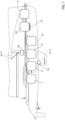
Figure 3 is a cross section according to the line A-A ofFigure 2 and shows a hydraulic cylinder forming part of the energy conversion system. - In
Figure 1 ,reference numeral 1 is used to indicate, as a whole, a boat (partially and schematically illustrated), in particular a sail boat. - The
boat 1 comprises ahydraulic system 5, of known type and schematically illustrated, for feeding oil under pressure to a plurality of hydraulic users (which include, for example, at least one hydraulic cylinder 21). - The boat further comprises a plurality of
components 10 which are subjected, during navigation, to forces or accelerations suitable to cause an oscillatory or vibratory motion on thesame components 10. In particular, such forces or accelerations can be defined by external loads of variable magnitude due, for example, to normal changes in wind speed and direction, wave motion, normal variations in water thrust on parts immersed in water, or aerodynamic loads on the sails, etc. - According to an embodiment, the
components 10 are defined by movable members coupled torespective actuators 20, which are operated to keepsuch components 10 in a predefined position. For example, theactuators 20 can be defined by: -
hydraulic cylinders 21 supplied and operated by thesystem 5, for example to keep acomponent 10 in a given position, defined by a movable member 22 immersed in water (a hydrofoil, a keel, etc.) and/or - cables or
ropes 23, which keep acomponent 10 defined by a sail 24 deployed and can be tensioned by electric motors, hydraulic actuators, pneumatic actuators, or so-called winches (i.e., manually manoeuvred winches), not illustrated. - According to other embodiments, the
components 10 are arranged in a predefined position and are constrained to afixed structure 30 of theboat 1, and thus are not operated by an actuator, but are naturally provided with an oscillation or a vibration due to variable external loads. - According to other embodiments, the
components 10 are defined by masses which are coupled to thefixed structure 30 so as to move substantially freely and are subject to natural inertial forces, due to wave motion and/or the consequent rocking of the boat, whereby they have an oscillatory motion of an inertial nature. - In general, the
components 10 potentially having vibratory or oscillatory motion during navigation may be of a different type with respect to those mentioned above, and are known to the person skilled in the art, whereby they are not listed in detail here for the sake of brevity. - Furthermore, the same situation (with components potentially having an oscillatory or vibratory motion) can also be found on other types of vehicles, provided with a hydraulic system.
- According to the present invention, the
boat 1 comprises anenergy conversion system 100 configured so as to recover energy which is naturally associated with the aforesaid oscillations/vibrations, and thus convert this energy into a hydraulic pressure, which can be transferred to thehydraulic system 5 and used in the latter (for example to operate the hydraulic cylinders 21). - With reference to the diagram in
Figure 2 , theenergy conversion system 100 comprises ahydraulic circuit 101 connected to thehydraulic system 5. In particular, thehydraulic circuit 101 comprises ahigh pressure branch 102 and alow pressure branch 103, respectively connected to adelivery branch 104 and to areturn branch 105 of thehydraulic system 5, by one ormore valves 106. - Preferably, the
hydraulic circuit 101 further comprises ahigh pressure accumulator 108, of known type and not described in detail, arranged along thehigh pressure branch 102 and configured so as to receive and accumulate oil under pressure, and thus feed the accumulated oil towards the delivery branch 104 (opening the valves 106). More preferably, thehydraulic circuit 101 further comprises alow pressure accumulator 109, of known type and not described in detail, arranged along thelow pressure branch 103, and configured so as to receive oil from thereturn branch 105. - The
energy conversion system 100 further comprises ahydraulic cylinder 120 which couples one of thecomponents 10 to a corresponding actuator 20 (or to the fixed structure 30). Thehydraulic cylinder 120 comprises abarrel 121 and arod 122, which extends along anaxis 123 and has an axial end arranged outside thebarrel 121. In particular, thebarrel 121 is fixed directly to the actuator 20 (or to the fixed structure 30), and the outer end of therod 122 is connected, directly or indirectly, to thecomponent 10. However, an opposite configuration could be envisaged, with the axial end of therod 122 fixed directly to the actuator 20 (or to the fixed structure 30), and with thebarrel 121 connected, directly or indirectly, to thecomponent 10. - With reference to
Figure 3 , thehydraulic cylinder 120 further comprises apiston 124, which is axially arranged at an intermediate portion of therod 122, is fixed with respect to the latter, and is coupled to aninner surface 125 of thebarrel 121 so as to be able to axially move and so as to axially separate, in a fluid-tight manner, twochambers 126 provided inside thebarrel 121. - In particular, the two
chambers 126 are delimited radially by theinner surface 125, and axially byrespective bottom walls 128, facing thepiston 124 and arranged on opposite axial parts of thepiston 124. Preferably, therod 122 projects axially from both opposite faces of thepiston 124, i.e., in bothchambers 126, and axially crosses bothbottom walls 128 in a fluid-tight manner. More in particular, therod 122 has the same diameter in bothchambers 126. - Preferably, the
chambers 126 houserespective spring members 132, axially coupled against thepiston 124, on one side, and against therespective bottom walls 128, on the other side. More preferably, each of thespring members 132 is defined by a respective set of disc springs. - In rest conditions (i.e., in the absence of pressure in the
chambers 126, and in the absence of forces acting on the rod 122) the two axial elastic thrusts of thespring members 132 are opposite each other and tend to keep thepiston 124 in an intermediate reference position. Preferably, thespring members 132 are equal and symmetrical to one another, whereby the reference position is arranged centrally between thebottom walls 128. - According to variants not illustrated, to define a reference position for the
piston 124, it is sufficient to provide even only one of the twospring members 132, and their housing inside thechambers 126 is not essential. - As diagrammed in
Figure 2 , each of the twochambers 126 has arespective inlet 135 communicating with thelow pressure branch 103 by acorresponding check valve 137, and arespective outlet 138 communicating with thehigh pressure branch 102 by acorresponding check valve 140. Thecheck valves low pressure branch 103 towards thechambers 126 and from the latter towards thehigh pressure branch 102; in other words, thecheck valves check valves 137 communicate with thelow pressure branch 103 through thelow pressure accumulator 109, and thecheck valves 140 communicate with thehigh pressure branch 102 through thehigh pressure accumulator 108. - It is therefore evident that the
hydraulic cylinder 120 is a double-acting cylinder. However, according to a variant not illustrated, thehydraulic cylinder 120 could be of the single-acting type, with only one of thechambers 126 connected to thehydraulic circuit 101. - Still with reference to
Figures 2 and3 , based on the oscillations or vibrations of thecomponent 10 along theaxis 123, therod 122 and therefore thepiston 124 move axially starting from the aforesaid reference position, against the positioning/centring action which is exerted by the thrust of thespring members 132. Thechambers 126 and thehydraulic circuit 101 are filled with oil: as a consequence of the axial movement of thepiston 124, one of the twochambers 126 increases the volume thereof and therefore sucks oil from thelow pressure branch 103, through thecorresponding check valve 137 and thecorresponding inlet 135, while theother chamber 126 tends to decrease in volume, and the oil therein is compressed. Such oil then flows towards thehigh pressure branch 102 through thecorresponding outlet 138. - When the movement direction of the
rod 122 is reversed, the behaviour of the twochambers 126 is also reversed. - It is therefore evident that the
hydraulic cylinder 120 defines an reciprocating linear pump, which is operated by the oscillation or vibration of thecomponent 10 and pressurizes the oil in the high pressure branch 102 (and, in more detail, in the high pressure accumulator 108). In other words, thehydraulic cylinder 120 converts the natural oscillatory or vibratory motion of thecomponent 10 into a hydraulic pressure which becomes available in thehigh pressure accumulator 108. As a direct consequence, it will be possible to feed oil under pressure from thehigh pressure accumulator 108 to thedelivery branch 104, opening the valves 106 (preferably with a simultaneous outflow of oil from thereturn branch 105 towards the low pressure branch 103) . - In the preferred embodiment illustrated in
Figure 2 , thehydraulic circuit 101 further comprises a by-pass pump 150, which connects thelow pressure branch 103 to thehigh pressure branch 102, in parallel to thehydraulic cylinder 120, and is operated (for example by an electric motor not illustrated) when the movement of therod 122 is insufficient for pressurizing thehigh pressure accumulator 108. In other words, oil under pressure can be fed by thepump 150 from thelow pressure branch 103 to thehigh pressure accumulator 108, by-passing thehydraulic cylinder 120. In particular, thepump 150 can be activated and deactivated in response to a pressure signal provided by a sensor, not illustrated, associated with the high pressure accumulator 108: for example, thepump 150 is activated and deactivated when such a signal becomes lower and, respectively, higher than two predefined threshold values, so as to maintain the pressure in thehigh pressure accumulator 108 in the range between such values. - In the embodiments in which the
components 10 are kept in a given position by theactuators 20 and are subjected to loads of variable magnitude,such components 10 can be provided with an axial clearance around such a position. In other words, the components 10 (sails 24, movable members 22, etc.) are left to oscillate around a predefined position, instead of being kept perfectly stopped by theactuators 20 in such a position. - This axial oscillation clearance must be relatively small and is defined by the maximum axial excursion of the
piston 124 inside thebarrel 121. - This excursion is adjustable in the preferred embodiment illustrated in
Figure 3 , thanks to the fact that the twobottom walls 128 are floating along theaxis 123 with respect to thebarrel 121 and therod 122. - In fact, the
bottom walls 128 are coupled in a fluid-tight manner to theinner surface 125 and to therod 122, and axially delimitrespective preloading chambers 142, provided at opposite axial ends of thebarrel 121. Thechambers 142 are used in a preliminary or initial setting phase, before using thehydraulic cylinder 120 as a reciprocating linear pump. In this phase, theenergy conversion system 100 is set up to set the maximum axial excursion of thepiston 124. In detail, thechambers 142 have respective inlet/outlet ports 144, connected to a source ofoil 145 under pressure, for example by a valve 146 (Figure 3 ); in the particular example illustrated, thesource 145 is defined by thehigh pressure branch 102, but could be defined by thehydraulic system 5, or by another oil supply system, of an independent type. When thevalve 146 is opened, thesource 145 feeds oil under pressure in bothchambers 142 through theports 144. The pressure of this oil exerts the same axial force on thebottom walls 128, since the latter have the same outer diameter. Such an axial force axially moves bothbottom walls 128 towards thepiston 124 and therefore compresses thespring members 132 against thepiston 124. In other words, a preload is provided to bothspring members 132 by the pressurization of the twochambers 142. - During this pressurization, the reference position of the
piston 124 remains substantially unchanged, since the compression acting on thebottom walls 128 is equal, and thespring members 132 are equal and symmetrical with one another with respect to the piston 124 (in summary, thespring members 132 have the same rigidity). - During this setting, preferably, the pressurization of the
chambers 142 ends when thespring members 132 reach a predefined deformation and/or when thebottom walls 128 reach a predefined axial position. At this point, the oil present in each of the twochambers 142 remains closed and isolated, whereby it tends to define a rigid system which keeps the correspondingbottom wall 128 in a fixed axial position. This axial position of thebottom walls 128 will define, in practice, a new end-stroke for thepiston 124 during normal use of thehydraulic cylinder 120 as a reciprocating linear pump. - During this use, as mentioned above, the
hydraulic cylinder 120 allows thecomponent 10 to oscillate or vibrate around a predefined position thereof, corresponding to the reference position of thepiston 124, while therod 122 transfers, to thesame piston 124, the force/acceleration which causes such oscillation/vibration. Thanks to the energy associated with the transferred force/acceleration, thepiston 124 pressurizes the oil present in thechambers 126, with a reciprocating motion, and thus pumps the oil in thehigh pressure accumulator 108 through the valves 137: it is therefore evident that theenergy conversion system 100 pressurizes thehigh pressure branch 102 and, therefore, thehydraulic system 5 by exploiting an energy which is naturally associated with oscillatory or vibratory motions of thecomponents 10, so as to save energy. - The fact that the
hydraulic cylinder 120 is double-acting allows pumping oil regardless of the movement direction of therod 122. Furthermore, the presence of twochambers 142 for adjusting the excursion of thepiston 124 allows keeping thepiston 124 in a central position in rest conditions (regardless of the preload assigned to the spring members 132) . - Furthermore, the compression of the oil in the
chambers 126 by thepiston 124 can also be used to dampen the magnitude of the oscillatory or vibratory motion of thecomponents 10, with respect to a reference situation in which thehydraulic cylinder 120 is not provided. - Other advantages are then evident to a person skilled in the art on the basis of what is set forth in the present discussion and illustrated in the accompanying drawings.
- Finally, it is evident that modifications and variants can be made to the vehicle described above without however departing from the scope of protection defined by the appended claims.
- In particular, the dimensions and proportions between the various parts of the
hydraulic cylinder 120 could be different from what is schematically illustrated and simplified in the accompanying figures. Furthermore, thebottom walls 128 could be fixed with respect to thebarrel 121, thus excluding the possibility of adjusting the axial excursion of thepiston 124; or one of the twobottom walls 128 could be fixed, and the other floating.
Claims (14)
- A vehicle comprising- a hydraulic system (5);- a component (10) having, in use, an oscillatory or vibratory motion;- an energy conversion system (100) comprising:said component (10) being connected to one of said barrel (121) and said rod (122) so as to make said hydraulic cylinder (120) operate as a reciprocating linear pump in response to said oscillatory/vibratory motion.a) a hydraulic circuit (101) connectable to said hydraulic system (5) for transferring a flow of oil under pressure and comprising a high pressure branch (102) and a low pressure branch (103);b) a hydraulic cylinder (120) comprising:(1) a barrel (121);(2) a rod (122), which extends along an axis (123) and is axially movable with respect to said barrel (121) ;(3) a piston (124), fixed with respect to said rod (122) and coupled to said barrel (121) in a fluid-tight manner so as to axially separate two chambers (126) from each other; at least one of said chambers (126) communicating with said high pressure branch (102) and with said low pressure branch (103) by respective check valves (137,140), which allow oil flows only from said hydraulic cylinder (120) to said high pressure branch (102) and from said low pressure branch (103) to said hydraulic cylinder (120);(4) at least one spring member (132) configured to place said piston (124) in an axial reference position with respect to said barrel (121) in rest conditions;
- The vehicle according to claim 1, wherein said vehicle is defined by a boat (1).
- The vehicle according to any one of the preceding claims, wherein both said chambers (126) communicate with said high pressure branch (102) and with said low pressure branch (103) by said check valves (137,140), and wherein the reference position in rest conditions is an intermediate axial position defined by two spring members (132) arranged on opposite axial sides of said piston (124).
- The vehicle according to any one of the preceding claims, wherein said spring member (132) is housed in one of said chambers (128) and is axially arranged between said piston (124) and a bottom wall (128).
- The vehicle according to claim 4, wherein said bottom wall (128) is axially floating with respect to said barrel (121) and said rod (121), so as to define, with said barrel (121), a preloading chamber (142), which can be pressurized during a preliminary setting phase to move said bottom wall (128) towards said piston (124) and vary a preload of said spring member (132).
- The vehicle according to claim 5, wherein said chambers (126) house respective spring members (132), axially arranged between said piston (124) and respective bottom walls (128), which are axially floating with respect to said barrel (121) and said rod (121), so as to define, with said barrel (121), respective preloading chambers (142), which can be pressurized during the preliminary setting phase.
- The vehicle according to any one of the preceding claims, wherein each of said spring members is defined by a respective set of disc springs.
- The vehicle according to any one of the preceding claims, wherein said hydraulic circuit (101) comprises a high pressure accumulator (108) arranged along said high pressure branch (102).
- The vehicle according to any one of the preceding claims, wherein said hydraulic circuit (101) comprises a low pressure accumulator (109) arranged along said low pressure branch (103).
- The vehicle according to any one of the preceding claims, wherein said hydraulic circuit (101) comprises a pump (150) connecting said low pressure branch (103) to said high pressure branch (102), in parallel with said hydraulic cylinder (120).
- The vehicle according to any one of the preceding claims, wherein the other one of said barrel (121) and said rod (122) is fixed to an actuator (20), operated to maintain said component (10) around a given position.
- The vehicle according to claim 11, wherein the vehicle comprises at least one hydraulic cylinder actuator (21) operated by said hydraulic system (5), and wherein said actuator (20) is defined by said hydraulic cylinder actuator (21) .
- The vehicle according to claim 11, wherein the vehicle comprises at least one cable or rope (23), in tension, and wherein said actuator (20) is defined by said cable or rope (23) .
- The vehicle according to any one of claims 1 to 10, wherein the vehicle (1) comprises a fixed structure (30), and wherein the other one of said barrel (121) and said rod (122) is fixed to said fixed structure (30).
Applications Claiming Priority (1)
| Application Number | Priority Date | Filing Date | Title |
|---|---|---|---|
| IT102023000025704A IT202300025704A1 (en) | 2023-12-01 | 2023-12-01 | VEHICLE, ESPECIALLY A VESSEL, WITH AN ENERGY CONVERSION SYSTEM TO GENERATE HYDRAULIC PRESSURE |
Publications (1)
| Publication Number | Publication Date |
|---|---|
| EP4563808A1 true EP4563808A1 (en) | 2025-06-04 |
Family
ID=90458253
Family Applications (1)
| Application Number | Title | Priority Date | Filing Date |
|---|---|---|---|
| EP24215012.6A Pending EP4563808A1 (en) | 2023-12-01 | 2024-11-25 | Veicolo, in particolare imbarcazione, con un sistema di conversione di energia per generare una pressione idraulica |
Country Status (3)
| Country | Link |
|---|---|
| EP (1) | EP4563808A1 (en) |
| IT (1) | IT202300025704A1 (en) |
| WO (1) | WO2025114851A1 (en) |
Citations (3)
| Publication number | Priority date | Publication date | Assignee | Title |
|---|---|---|---|---|
| US20180094617A1 (en) * | 2016-10-04 | 2018-04-05 | Richard Neifeld | Device and Method to Convert Reciprocating Linear Motion into Linear Fluid Flow |
| CN111472922A (en) * | 2020-06-01 | 2020-07-31 | 青岛科技大学 | Power generation device for ship by utilizing wave energy |
| WO2020193725A1 (en) * | 2019-03-27 | 2020-10-01 | Institut Francais De Recherche Pour L'exploitation De La Mer (Ifremer) | Wave energy conversion and propulsion device |
-
2023
- 2023-12-01 IT IT102023000025704A patent/IT202300025704A1/en unknown
-
2024
- 2024-11-25 WO PCT/IB2024/061778 patent/WO2025114851A1/en active Pending
- 2024-11-25 EP EP24215012.6A patent/EP4563808A1/en active Pending
Patent Citations (3)
| Publication number | Priority date | Publication date | Assignee | Title |
|---|---|---|---|---|
| US20180094617A1 (en) * | 2016-10-04 | 2018-04-05 | Richard Neifeld | Device and Method to Convert Reciprocating Linear Motion into Linear Fluid Flow |
| WO2020193725A1 (en) * | 2019-03-27 | 2020-10-01 | Institut Francais De Recherche Pour L'exploitation De La Mer (Ifremer) | Wave energy conversion and propulsion device |
| CN111472922A (en) * | 2020-06-01 | 2020-07-31 | 青岛科技大学 | Power generation device for ship by utilizing wave energy |
Also Published As
| Publication number | Publication date |
|---|---|
| WO2025114851A1 (en) | 2025-06-05 |
| IT202300025704A1 (en) | 2025-06-01 |
Similar Documents
| Publication | Publication Date | Title |
|---|---|---|
| US7971545B2 (en) | Watercraft having a kite-like element | |
| US9593717B2 (en) | Water lubricated bearing device | |
| US5179837A (en) | Wave powered energy generator | |
| WO2004067435A1 (en) | System for storing, delivering and recovering energy | |
| CA2808322C (en) | Wave energy conversion | |
| EP4563808A1 (en) | Veicolo, in particolare imbarcazione, con un sistema di conversione di energia per generare una pressione idraulica | |
| JP4926507B2 (en) | Reservoir built-in actuator | |
| EP3132136B1 (en) | Wave energy conversion apparatus | |
| RU2374128C2 (en) | Ship with kite-like element | |
| CA2672683C (en) | Oscillating water column energy accumulator | |
| KR20200060949A (en) | Active suspension system for vehicle | |
| CN106170624B (en) | Wave energy converter | |
| WO2004016947A1 (en) | Energy recycling pump | |
| GB2567994A (en) | Hydraulic system and a spring-damper mechanism | |
| KR101194751B1 (en) | Ship | |
| KR20230125846A (en) | torsional vibration damper | |
| JP6909531B1 (en) | Wave power engine | |
| CN201934561U (en) | Damping cylinder for deploying and retracting device of high-speed work boat | |
| KR101413304B1 (en) | Piston rod unit with integrated oil-water separator for ships | |
| KR101624876B1 (en) | Ship including device for reducing a fluctuation pressure induced by propeller | |
| US20170292494A1 (en) | Assembly for Converting Linear and Rotational Motions of a Floating Vessel to Electricity | |
| RU2006130440A (en) | SHIP MOVABLE AND POWER SUPPLY BY PUMP | |
| SU1082681A2 (en) | Thrust-relieving arrangement | |
| KR200407217Y1 (en) | Top bracing to prevent lateral vibration of the engine | |
| JP2007040437A (en) | Accumulation method, on-vehicle pump |
Legal Events
| Date | Code | Title | Description |
|---|---|---|---|
| PUAI | Public reference made under article 153(3) epc to a published international application that has entered the european phase |
Free format text: ORIGINAL CODE: 0009012 |
|
| STAA | Information on the status of an ep patent application or granted ep patent |
Free format text: STATUS: THE APPLICATION HAS BEEN PUBLISHED |
|
| AK | Designated contracting states |
Kind code of ref document: A1 Designated state(s): AL AT BE BG CH CY CZ DE DK EE ES FI FR GB GR HR HU IE IS IT LI LT LU LV MC ME MK MT NL NO PL PT RO RS SE SI SK SM TR |
|
| STAA | Information on the status of an ep patent application or granted ep patent |
Free format text: STATUS: REQUEST FOR EXAMINATION WAS MADE |
|
| 17P | Request for examination filed |
Effective date: 20251204 |
|
| STAA | Information on the status of an ep patent application or granted ep patent |
Free format text: STATUS: EXAMINATION IS IN PROGRESS |
|
| 17Q | First examination report despatched |
Effective date: 20260331 |