CN106170624B - Wave energy converter - Google Patents
Wave energy converter Download PDFInfo
- Publication number
- CN106170624B CN106170624B CN201580005072.8A CN201580005072A CN106170624B CN 106170624 B CN106170624 B CN 106170624B CN 201580005072 A CN201580005072 A CN 201580005072A CN 106170624 B CN106170624 B CN 106170624B
- Authority
- CN
- China
- Prior art keywords
- buoy
- negative spring
- float
- equilibrium position
- displacement
- Prior art date
- Legal status (The legal status is an assumption and is not a legal conclusion. Google has not performed a legal analysis and makes no representation as to the accuracy of the status listed.)
- Active
Links
Images


Classifications
-
- F—MECHANICAL ENGINEERING; LIGHTING; HEATING; WEAPONS; BLASTING
- F03—MACHINES OR ENGINES FOR LIQUIDS; WIND, SPRING, OR WEIGHT MOTORS; PRODUCING MECHANICAL POWER OR A REACTIVE PROPULSIVE THRUST, NOT OTHERWISE PROVIDED FOR
- F03B—MACHINES OR ENGINES FOR LIQUIDS
- F03B13/00—Adaptations of machines or engines for special use; Combinations of machines or engines with driving or driven apparatus; Power stations or aggregates
- F03B13/12—Adaptations of machines or engines for special use; Combinations of machines or engines with driving or driven apparatus; Power stations or aggregates characterised by using wave or tide energy
- F03B13/14—Adaptations of machines or engines for special use; Combinations of machines or engines with driving or driven apparatus; Power stations or aggregates characterised by using wave or tide energy using wave energy
- F03B13/16—Adaptations of machines or engines for special use; Combinations of machines or engines with driving or driven apparatus; Power stations or aggregates characterised by using wave or tide energy using wave energy using the relative movement between a wave-operated member, i.e. a "wom" and another member, i.e. a reaction member or "rem"
- F03B13/18—Adaptations of machines or engines for special use; Combinations of machines or engines with driving or driven apparatus; Power stations or aggregates characterised by using wave or tide energy using wave energy using the relative movement between a wave-operated member, i.e. a "wom" and another member, i.e. a reaction member or "rem" where the other member, i.e. rem is fixed, at least at one point, with respect to the sea bed or shore
- F03B13/1885—Adaptations of machines or engines for special use; Combinations of machines or engines with driving or driven apparatus; Power stations or aggregates characterised by using wave or tide energy using wave energy using the relative movement between a wave-operated member, i.e. a "wom" and another member, i.e. a reaction member or "rem" where the other member, i.e. rem is fixed, at least at one point, with respect to the sea bed or shore and the wom is tied to the rem
- F03B13/1895—Adaptations of machines or engines for special use; Combinations of machines or engines with driving or driven apparatus; Power stations or aggregates characterised by using wave or tide energy using wave energy using the relative movement between a wave-operated member, i.e. a "wom" and another member, i.e. a reaction member or "rem" where the other member, i.e. rem is fixed, at least at one point, with respect to the sea bed or shore and the wom is tied to the rem where the tie is a tension/compression member
-
- F—MECHANICAL ENGINEERING; LIGHTING; HEATING; WEAPONS; BLASTING
- F03—MACHINES OR ENGINES FOR LIQUIDS; WIND, SPRING, OR WEIGHT MOTORS; PRODUCING MECHANICAL POWER OR A REACTIVE PROPULSIVE THRUST, NOT OTHERWISE PROVIDED FOR
- F03B—MACHINES OR ENGINES FOR LIQUIDS
- F03B13/00—Adaptations of machines or engines for special use; Combinations of machines or engines with driving or driven apparatus; Power stations or aggregates
- F03B13/12—Adaptations of machines or engines for special use; Combinations of machines or engines with driving or driven apparatus; Power stations or aggregates characterised by using wave or tide energy
- F03B13/14—Adaptations of machines or engines for special use; Combinations of machines or engines with driving or driven apparatus; Power stations or aggregates characterised by using wave or tide energy using wave energy
- F03B13/16—Adaptations of machines or engines for special use; Combinations of machines or engines with driving or driven apparatus; Power stations or aggregates characterised by using wave or tide energy using wave energy using the relative movement between a wave-operated member, i.e. a "wom" and another member, i.e. a reaction member or "rem"
- F03B13/18—Adaptations of machines or engines for special use; Combinations of machines or engines with driving or driven apparatus; Power stations or aggregates characterised by using wave or tide energy using wave energy using the relative movement between a wave-operated member, i.e. a "wom" and another member, i.e. a reaction member or "rem" where the other member, i.e. rem is fixed, at least at one point, with respect to the sea bed or shore
- F03B13/1805—Adaptations of machines or engines for special use; Combinations of machines or engines with driving or driven apparatus; Power stations or aggregates characterised by using wave or tide energy using wave energy using the relative movement between a wave-operated member, i.e. a "wom" and another member, i.e. a reaction member or "rem" where the other member, i.e. rem is fixed, at least at one point, with respect to the sea bed or shore and the wom is hinged to the rem
- F03B13/181—Adaptations of machines or engines for special use; Combinations of machines or engines with driving or driven apparatus; Power stations or aggregates characterised by using wave or tide energy using wave energy using the relative movement between a wave-operated member, i.e. a "wom" and another member, i.e. a reaction member or "rem" where the other member, i.e. rem is fixed, at least at one point, with respect to the sea bed or shore and the wom is hinged to the rem for limited rotation
-
- F—MECHANICAL ENGINEERING; LIGHTING; HEATING; WEAPONS; BLASTING
- F03—MACHINES OR ENGINES FOR LIQUIDS; WIND, SPRING, OR WEIGHT MOTORS; PRODUCING MECHANICAL POWER OR A REACTIVE PROPULSIVE THRUST, NOT OTHERWISE PROVIDED FOR
- F03B—MACHINES OR ENGINES FOR LIQUIDS
- F03B13/00—Adaptations of machines or engines for special use; Combinations of machines or engines with driving or driven apparatus; Power stations or aggregates
- F03B13/12—Adaptations of machines or engines for special use; Combinations of machines or engines with driving or driven apparatus; Power stations or aggregates characterised by using wave or tide energy
- F03B13/14—Adaptations of machines or engines for special use; Combinations of machines or engines with driving or driven apparatus; Power stations or aggregates characterised by using wave or tide energy using wave energy
- F03B13/16—Adaptations of machines or engines for special use; Combinations of machines or engines with driving or driven apparatus; Power stations or aggregates characterised by using wave or tide energy using wave energy using the relative movement between a wave-operated member, i.e. a "wom" and another member, i.e. a reaction member or "rem"
- F03B13/18—Adaptations of machines or engines for special use; Combinations of machines or engines with driving or driven apparatus; Power stations or aggregates characterised by using wave or tide energy using wave energy using the relative movement between a wave-operated member, i.e. a "wom" and another member, i.e. a reaction member or "rem" where the other member, i.e. rem is fixed, at least at one point, with respect to the sea bed or shore
- F03B13/1845—Adaptations of machines or engines for special use; Combinations of machines or engines with driving or driven apparatus; Power stations or aggregates characterised by using wave or tide energy using wave energy using the relative movement between a wave-operated member, i.e. a "wom" and another member, i.e. a reaction member or "rem" where the other member, i.e. rem is fixed, at least at one point, with respect to the sea bed or shore and the wom slides relative to the rem
-
- F—MECHANICAL ENGINEERING; LIGHTING; HEATING; WEAPONS; BLASTING
- F03—MACHINES OR ENGINES FOR LIQUIDS; WIND, SPRING, OR WEIGHT MOTORS; PRODUCING MECHANICAL POWER OR A REACTIVE PROPULSIVE THRUST, NOT OTHERWISE PROVIDED FOR
- F03B—MACHINES OR ENGINES FOR LIQUIDS
- F03B13/00—Adaptations of machines or engines for special use; Combinations of machines or engines with driving or driven apparatus; Power stations or aggregates
- F03B13/12—Adaptations of machines or engines for special use; Combinations of machines or engines with driving or driven apparatus; Power stations or aggregates characterised by using wave or tide energy
- F03B13/14—Adaptations of machines or engines for special use; Combinations of machines or engines with driving or driven apparatus; Power stations or aggregates characterised by using wave or tide energy using wave energy
- F03B13/16—Adaptations of machines or engines for special use; Combinations of machines or engines with driving or driven apparatus; Power stations or aggregates characterised by using wave or tide energy using wave energy using the relative movement between a wave-operated member, i.e. a "wom" and another member, i.e. a reaction member or "rem"
- F03B13/18—Adaptations of machines or engines for special use; Combinations of machines or engines with driving or driven apparatus; Power stations or aggregates characterised by using wave or tide energy using wave energy using the relative movement between a wave-operated member, i.e. a "wom" and another member, i.e. a reaction member or "rem" where the other member, i.e. rem is fixed, at least at one point, with respect to the sea bed or shore
- F03B13/1885—Adaptations of machines or engines for special use; Combinations of machines or engines with driving or driven apparatus; Power stations or aggregates characterised by using wave or tide energy using wave energy using the relative movement between a wave-operated member, i.e. a "wom" and another member, i.e. a reaction member or "rem" where the other member, i.e. rem is fixed, at least at one point, with respect to the sea bed or shore and the wom is tied to the rem
-
- F—MECHANICAL ENGINEERING; LIGHTING; HEATING; WEAPONS; BLASTING
- F03—MACHINES OR ENGINES FOR LIQUIDS; WIND, SPRING, OR WEIGHT MOTORS; PRODUCING MECHANICAL POWER OR A REACTIVE PROPULSIVE THRUST, NOT OTHERWISE PROVIDED FOR
- F03B—MACHINES OR ENGINES FOR LIQUIDS
- F03B13/00—Adaptations of machines or engines for special use; Combinations of machines or engines with driving or driven apparatus; Power stations or aggregates
- F03B13/12—Adaptations of machines or engines for special use; Combinations of machines or engines with driving or driven apparatus; Power stations or aggregates characterised by using wave or tide energy
- F03B13/14—Adaptations of machines or engines for special use; Combinations of machines or engines with driving or driven apparatus; Power stations or aggregates characterised by using wave or tide energy using wave energy
- F03B13/16—Adaptations of machines or engines for special use; Combinations of machines or engines with driving or driven apparatus; Power stations or aggregates characterised by using wave or tide energy using wave energy using the relative movement between a wave-operated member, i.e. a "wom" and another member, i.e. a reaction member or "rem"
- F03B13/20—Adaptations of machines or engines for special use; Combinations of machines or engines with driving or driven apparatus; Power stations or aggregates characterised by using wave or tide energy using wave energy using the relative movement between a wave-operated member, i.e. a "wom" and another member, i.e. a reaction member or "rem" wherein both members, i.e. wom and rem are movable relative to the sea bed or shore
-
- F—MECHANICAL ENGINEERING; LIGHTING; HEATING; WEAPONS; BLASTING
- F05—INDEXING SCHEMES RELATING TO ENGINES OR PUMPS IN VARIOUS SUBCLASSES OF CLASSES F01-F04
- F05B—INDEXING SCHEME RELATING TO WIND, SPRING, WEIGHT, INERTIA OR LIKE MOTORS, TO MACHINES OR ENGINES FOR LIQUIDS COVERED BY SUBCLASSES F03B, F03D AND F03G
- F05B2260/00—Function
- F05B2260/50—Kinematic linkage, i.e. transmission of position
- F05B2260/502—Kinematic linkage, i.e. transmission of position involving springs
-
- Y—GENERAL TAGGING OF NEW TECHNOLOGICAL DEVELOPMENTS; GENERAL TAGGING OF CROSS-SECTIONAL TECHNOLOGIES SPANNING OVER SEVERAL SECTIONS OF THE IPC; TECHNICAL SUBJECTS COVERED BY FORMER USPC CROSS-REFERENCE ART COLLECTIONS [XRACs] AND DIGESTS
- Y02—TECHNOLOGIES OR APPLICATIONS FOR MITIGATION OR ADAPTATION AGAINST CLIMATE CHANGE
- Y02E—REDUCTION OF GREENHOUSE GAS [GHG] EMISSIONS, RELATED TO ENERGY GENERATION, TRANSMISSION OR DISTRIBUTION
- Y02E10/00—Energy generation through renewable energy sources
- Y02E10/30—Energy from the sea, e.g. using wave energy or salinity gradient
Abstract
A wave energy converter (1) for extracting energy from sea waves, comprising: a buoy (2) arranged to oscillate about an equilibrium position (4) relative to a reference point (3); and a negative spring means (10) connected between the buoy (2) and the reference point (3), wherein the negative spring means (10) is adapted to provide a positive force in a displacement direction when the buoy (2) is moved away from the equilibrium position (4).
Description
Technical Field
The present invention relates to a wave energy converter for extracting energy from sea waves and a method for extracting energy from sea waves. The harvested energy may be used, for example, to produce electricity.
Background
Energy is transported by ocean waves. In the pursuit of energy sources with low carbon emissions, there has been much work in converting ocean wave energy into useful forms of energy (e.g., electricity). One area of such work has been focused on so-called point absorbers. Point absorbers are actually individual buoys floating on the ocean surface that are displaced by incoming ocean waves. This displacement can be used to convert wave energy into a useful form of energy. Examples of such point absorbers are given in WO 99/22137.
Furthermore, the use of pre-tensioned buoys is well known in the wave energy conversion field. The pre-tensioning of the buoy (e.g. by forcing it to submerge in some way to a depth greater than its natural floating depth) has the effect of providing a negative mass to the oscillating system, effectively reducing the inertia of the buoy and increasing its response to incoming waves.
Disclosure of Invention
Viewed from a first aspect, the present invention provides a wave energy converter for extracting energy from ocean waves, comprising: a buoy configured to oscillate about an equilibrium position relative to a reference point; and a negative spring arrangement connected between the float and the reference point, wherein the negative spring arrangement is adapted to exert a positive force in the displacement direction when the float is moved away from the equilibrium position.
By using a negative spring, it is possible to increase the range of motion of the float, since the negative spring effect will counteract the static stiffness of the float and the natural resistance of the float to oscillations, which is for example due to a balance between buoyancy and gravity. By using a negative spring, the buoy can be made to have a very low apparent stiffness over a given range of motion, which means that it can be designed to oscillate with greater amplitude of motion than existing buoys over a greater range of frequencies than affect existing buoys when excited by wave motion (i.e. increasing the wave frequency bandwidth that will lift the resonant oscillation of the buoy). The result of this is that a float with a negative spring as described above can be more easily and efficiently used as a source of energy conversion over a larger wave frequency range. It has been found that the use of negative springs can increase the transmitted energy of the heave buoy system by at least 100%. That is, in the experimental comparison of a heave buoy with a negative spring and a standard heave buoy (without a negative spring), the average power output is at least doubled compared to the standard system. The greater range of motion of the buoy can also simplify coupling the buoy to other devices for energy conversion (e.g., to mechanical or electromechanical devices). The invention may be used with pre-tensioned buoys or non-pre-tensioned buoys. However, the use of a pre-tensioned buoy may further increase the response of the buoy to incoming waves.
The incoming sea waves associated with wave energy conversion typically have a period of between 4s and 14s, and typically have a wave height of up to 5m, and in some extreme cases up to 10m or more.
The equilibrium position of the buoy is a position where there is no restoring force/acceleration experienced by the buoy when the buoy oscillates. This is typically the position that the buoy will be in relative to the datum point when no wave energy is present (i.e. when standing still) and without any effect that may result from a negative spring arrangement. The buoy may float on the surface of the ocean or may be semi-submerged or submerged.
The reference point is the point around which the buoy oscillates. A negative spring device is coupled between the float and the datum such that the spring device releases or stores energy when the float moves relative to the datum. The reference point may be a fixed point. The reference point may be fixed relative to the seabed or relative to a structure (e.g. a structure that experiences significantly less movement than the buoy). Such a structure may be a pier or a large floating/immersed/semi-immersed structure (i.e. a structure significantly larger than a floating buoy). The structure should not significantly oscillate at the same frequency as the float due to incoming wave energy so that the float can oscillate relative to the structure due to incoming wave energy. When the fixed point is attached to the seabed, it may be considered an absolute fixed point.
The oscillation may be a linear motion oscillation or a rotational oscillation or a combination of both. The global motion may be a superposition of several translational and/or oscillatory motions. Similarly, the spring means may comprise a spring element which releases or stores energy in the presence of linear or oscillatory motion. For example, a coil spring, a volute spring, or a gas piston spring may be compressed by linear motion and store energy that is released as the spring expands. A helical torsion spring or torsion bar will deform and store energy when undergoing rotational motion.
The negative spring means may be spring means capable of generating a force in the displacement direction of the buoy when the buoy is displaced from its equilibrium position. The negative spring arrangement may provide no force in the direction of oscillatory movement of the buoy when the buoy is in its equilibrium position. The amount of force provided by the negative spring arrangement in the direction of displacement of the float may vary as the float moves away from its equilibrium position. This force variation may be due to the geometry of the system. This change in force may come into play when the buoy is displaced from its equilibrium position. The force generated by the negative spring arrangement may be used to urge the buoy in an oscillating displacement direction. By careful design of the negative spring arrangement it is possible to match the force from the spring to other forces in the system, for example due to buoyancy and gravity of the buoy. In one example arrangement, the negative spring may provide an initial force that increases with displacement as the float moves away from the equilibrium position.
The negative spring arrangement may provide such a force by: the negative spring means is in a compressed state when the buoy is in its equilibrium position and is allowed to expand when the buoy is displaced from its equilibrium position. The negative spring may be in a state of maximum compression when the float is in its equilibrium position, for example for a linear spring, the distance from a reference point to the point where the negative spring connects to the float may be at a minimum when the float is in its equilibrium position. The negative spring means may act by urging the float against a fixed point as the float is displaced from its equilibrium position.
The negative spring arrangement may be configured to provide a negative stiffness to oppose the static stiffness of the float. The negative spring arrangement can produce an overall stiffness near the equilibrium point that is less than the static stiffness (without the negative spring). This static stiffness can typically be reduced by about 4/5 or more, depending on the other properties of the buoy system. The static stiffness may be reduced 9/10 or more. The stiffness can be reduced in this way for a given range of motion near the balance point. For a linear motion oscillator, the stiffness may be sufficiently reduced for displacements of about ± 1 to 5 m. The stiffness may be reduced throughout the available travel of the buoy. For a rotary oscillator, the stiffness is typically sufficiently reduced for displacements of about ± 0.1 to 0.5 rad. For displacements that are not near the equilibrium point, it may be allowed to increase the stiffness of the system.
The reduction in stiffness near the point of equilibrium results in a greatly reduced overall restoring force. This reduction in stiffness results in an increased bandwidth of the oscillating buoy, which results in the buoy having a greater amplitude of oscillation for a greater range of incoming wave frequencies. The efficiency of the wave energy converter is increased because it allows more wave energy to be converted in a wider wave frequency range.
The static stiffness S is a proportionality coefficient (or constant) between the restoring force experienced by the float and the displacement of the float from its equilibrium point. It is a concept related only to the oscillation of semi-submersible systems with considerable heave motion and systems rotating around an axis close to the mean sea level. The static stiffness is similar to the spring constant k in a standard mass/spring mechanical oscillator. For a linear motion oscillator, the static stiffness S is generally related to the restoring force by the relation S-F/z, where F is the restoring force and z is the displacement from the equilibrium position. For a rotary oscillator, the static stiffness is generally related to the restoring force by the relationship S τ/θ, where τ is the restoring moment and θ is the angular displacement from the equilibrium position. Reducing this static stiffness may therefore be considered to be similar to reducing the restoring force or moment (collectively referred to from now on as "restoring force") to which the buoy is subjected. As the buoy is displaced from its equilibrium position, the total force from the negative spring arrangement may be reduced. At a certain displacement, the total force from the negative spring arrangement (and thus the component of the force in the direction of displacement of the float) may be zero. This displacement is referred to herein as a threshold displacement. At displacements greater than the threshold displacement, the spring arrangement may provide a force in a direction opposite to the direction of displacement of the float from its equilibrium position. In this case, the negative spring means acts as a positive spring after a certain displacement.
This positive spring capability may help avoid or reduce reliance on the use of end stops. An end stop is typically required to limit the maximum displacement of the buoy away from its equilibrium point. The transition from a negative spring to a positive spring can act as an end stop, which means that no additional end stop assembly is required. Alternatively, a positive spring effect may mean that a weaker end stop may be used. The positive spring capability may therefore reduce the number of components present in the system and reduce wear in the system, as the float no longer needs to strike the end stop to limit its displacement or strike the end stop with less force.
The total force provided by the spring arrangement may initially increase as the displacement increases, and then it may decrease before it becomes a positive force at the threshold displacement. Due to the geometry of the system, the component of the force from the spring arrangement in the direction opposite to the float displacement direction may be further reduced, and the total force generated by the negative spring arrangement may increase as it expands since the threshold displacement has been exceeded.
As the buoy moves beyond a threshold displacement and the negative spring means starts to act with a positive total force, the wave energy converter can store energy. This energy can be seen as potential energy stored in the wave energy converter, which is generated by converting the kinetic energy of the buoy and/or the static potential energy of the buoy. This energy may be stored in a negative spring arrangement. The stored energy may be used later. The energy may be stored in one or more fluid (e.g., gas or liquid) accumulators. Pressurized fluid may be stored in the accumulator, the fluid having been compressed with the kinetic and/or static energy of the float. The accumulator may be in addition to the negative spring means and may be connected to the negative spring means. However, in case the negative spring means comprises a hydraulic/pneumatic/gas spring (see below), the accumulator may form part of the negative spring means, i.e. the accumulator may directly contribute to the spring characteristic of the negative spring means. In this case, an additional accumulator may also be provided to increase the energy storage capacity.
The negative spring means may be connected between the float and the datum by any suitable coupling. Such a coupling may allow for an articulated rotation of the negative spring arrangement relative to the buoy and the reference point during the oscillating movement of the buoy. The coupling may have any form known in the art suitable for this purpose. During operation of the wave energy converter, the position in which the negative spring means is in equilibrium with respect to the spring means has a maximum rotation around the reference point between-90 ° and +90 °. Preferably, this interval is between-70 ° and +70 °, between-50 ° and +50 °, or between-30 ° and +30 °.
The negative spring means may comprise a mechanical spring. The negative spring means may comprise a plurality of mechanical springs. The mechanical spring may be a coil spring, a pneumatic/pneumatic spring or a hydraulic spring. Pneumatic/pneumatic springs or hydraulic springs can be particularly effective in producing a negative spring effect. The mechanical spring may preferably comprise a hydraulic/power cylinder and a gas accumulator. In this case, a larger pressure range can be handled by the negative spring device.
The pneumatic/pneumatic spring or the hydraulic spring may comprise a fluid cylinder.
The negative spring means may comprise a controlled valve or a passive valve. These valves may be used to regulate and/or adjust the pressure within the hydraulic/pneumatic/gas spring. It is thus possible to vary, adjust and/or optimize the operation of the negative spring device. For example, it may be possible to vary, adjust and/or optimize the negative spring force/torque provided by the negative spring means; an optional threshold displacement; and/or an optional positive spring force/torque provided by a negative spring device.
These valves may be solenoid valves, hydraulic valves, gas-actuated valves, or pneumatic valves. These valves may be controlled by a controller. The state of the wave energy converter and/or the state of the water surrounding the wave energy converter can be measured or an estimate can be made. The measurement/estimation may be the instantaneous state of the wave energy converter and/or the surrounding water. For example, the measurements/estimates may be one or more of a motion, power take off (take off) dynamic variable of the buoy and/or a wave dynamic variable. The measurements/estimates may be used by the controller to control the valves.
In one embodiment, the reference point may be provided on a support member fixed relative to the seabed or structure, the buoy being configured to oscillate relative to the support member, the spring arrangement being coupled between the interior of the buoy and the support member.
The support member may be a rigid support member (e.g., a rod or column). The support member may be attached to the seabed or structure.
The support member may be a flexible support member (e.g. a cable or a flexible tube). The support member may be held taut, for example, between the seabed and the structure.
The buoy may be configured to undergo translational/linear motion oscillations. The force from the negative spring means may have a component in the direction of the linear displacement when the buoy is displaced from its equilibrium position. The reference point may be located at an equilibrium position of the oscillating buoy.
Alternatively or additionally, the buoy may be configured to undergo rotational oscillation. The float may oscillate at an angular displacement about a pivot point. The pivot point may be external to the float. The buoy may be connected to the pivot point by a connecting member. The connecting member may be rigid and may be connected to the centre of the buoy. A negative spring device may be coupled between the center of the float and the reference point. The closer the reference point is to the equilibrium position of the float, the greater will be the tangential force provided by the spring. Alternatively, a torsion spring arrangement may be used as the negative spring arrangement. When the buoy is displaced from its equilibrium position, the force from the negative spring arrangement has a component in the tangential direction of the oscillating buoy.
The reference point may be located at or near any position along the line between the equilibrium position and the pivot point, and preferably between the equilibrium position and the pivot point, and more preferably between the centre of the buoy when it is in its equilibrium position to the pivot point. The reference point may be located at a fixed position relative to the pivot point.
The wave energy converter may comprise a plurality of negative spring means. For example, when the buoy is configured to undergo linear motion, then there may be a plurality of spring devices extending in a radial direction from and spaced about an axis defined by the direction of translational motion. When the buoy is configured to undergo rotational oscillatory motion, then there may be a plurality of spring devices extending along a plane orthogonal to the tangent of the arc of motion of the buoy at the point of equilibrium. Thus, in each case, a plurality of negative spring means may be arranged to extend in different directions along a plane perpendicular to the direction of movement at the equilibrium position. Preferably, the plurality of spring means are arranged symmetrically. Preferably, all spring means are connected between the float and the same datum.
When a plurality of pneumatic, pneumatic or hydraulic springs are used, at least two of the plurality of spring means may be fluidly connected to each other such that the pressure of the fluid within the respective negative spring means remains equal. This fluid connection prevents uneven loading between the float and the datum. The fluid connection may be permanent. The fluid connection may selectively connect at least two multi-spring devices, for example in the manner of a valve. The fluid connection may comprise means for selectively connecting at least two multi-spring devices, such as valves. The fluid connection may comprise a pipe or hose connection and may further comprise a valve. The fluid connection may be between the cylinders of the spring.
For a linear system, the negative spring devices may be arranged in a star shape, e.g. a two-pointed star, a three-pointed star or a five-pointed star, around an axis along the direction of motion. When there is a symmetrical arrangement of this type, there may advantageously be no net force between the float and the support member, since the negative spring means is in a direction perpendicular to the direction of the support member. This can be achieved using symmetrically spaced negative springs of the same nature. In this case, all the force from the spring will be in the direction of movement, which may be the direction of the support member. For example, there may be three spring devices separated by 120 °, all three devices providing substantially equal force between the float and the support member.
The support member may pass through the center of the buoy. Due to the buoyancy of the buoy, the support member may be oriented in an oscillation direction, which may be the translational movement direction mentioned above. The direction may be substantially vertical.
Each negative spring means may comprise only one spring. This is the simplest arrangement and may for example be provided by a single spring which is in compression in the equilibrium position and perpendicular to the direction of the translational movement or to the tangential direction of the arc of the rotational movement.
Alternatively, the negative spring means, the or each negative spring means may comprise a set of springs, for example a pair of V-shaped corner springs, symmetrically distributed at the equilibrium position about a perpendicular to the direction of movement at the equilibrium position, such direction being for example the direction of translational movement or the tangent of the arc of rotational movement. The springs in each negative spring means may be in the same plane as the perpendicular and the direction of movement. In this case, the set of springs may extend from the connection of the datum (at the tip of the V) to corresponding points on the inner plane of the float (at both ends of the V). The points may be spaced apart in a direction substantially aligned with the direction of motion. During movement away from the equilibrium position, the spring (or set of springs) will provide a force having a component in the direction of movement, thus resulting in the addition of a negative stiffness. It will be appreciated that the angle of the spring means away from the vertical will increase during movement, which means that the component of the force in the direction of movement will increase as the force becomes more aligned with the direction of movement.
When pneumatic, pneumatic or hydraulic springs are used, at least two springs of the set of springs may be fluidly connected to each other such that the fluid pressure in the respective springs of the set of springs remains equal. Such a fluid connection may reduce friction in the system. The fluid connection may be permanent. The fluid connection may selectively connect at least two springs, for example in the manner of a valve. The fluid connection may comprise means for selectively connecting at least two springs, such as a valve. The fluid connection may comprise a pipe or hose connection and may further comprise a valve. The fluid connection may be between the cylinders of the spring.
Examples of springs used may be those manufactured by Sheffer corporation of Cincinnati (Cincinnati), Ohio, Inc., Parker Hydraulics corporation of Norwich, UK, and Bosch Rexroth corporation of Charlotte, North Carolina, USA. For pneumatic springs, it is designed to withstand maximum pressures of up to about 100bar, preferably up to 150bar, and a cylinder bore of between 10cm and 100 cm. The maximum pressure that can be withstood by the pneumatic spring may be up to about 10bar, preferably up to 15bar, and further preferably up to 20bar, while the bore of the cylinder may be between 30cm and 100 cm. For a hydraulic spring, it is designed to withstand a maximum pressure of up to about 200bar and the bore of the cylinder may be about 50 cm.
In the present invention, the buoy may have any known shape. For example, it may be substantially cylindrical or spherical.
The wave energy converter may be used as a pump or as an electrical energy generator. When functioning as a pump, the oscillating buoy may drive a hydraulic or pneumatic system to utilize energy. The hydraulic or pneumatic system may then be connected to an electrical generator. Alternatively, the oscillating buoy may generate electricity directly by an electromechanical device containing the necessary magnets and circuitry, as is known in the art. Such an electromechanical device may be part of the buoy or the buoy may be mechanically coupled to an external device.
In another aspect, the present invention provides a method of extracting energy from ocean waves, comprising: allowing the buoy to oscillate about an equilibrium position relative to a datum due to wave motion; and using a negative spring arrangement to provide a positive force between the float and the datum when the float is moved away from the equilibrium position, the positive force being in the direction of displacement between the float and the equilibrium position.
In another aspect, the present invention provides a method of extracting energy from ocean waves, comprising: allowing the buoy to oscillate about an equilibrium position relative to a datum due to wave motion; and providing a positive force between the float and the datum, the positive force being in the direction of displacement between the float and the equilibrium position.
The method(s) may include providing a positive force between the float and the reference point in a direction opposite to the displacement between the float and its equilibrium position if the displacement is greater than a threshold value.
The force between the float and the datum may be provided by a negative spring arrangement as described above. The method may comprise using a device having any or all of the features described above. The oscillation may be a linear motion oscillation or a rotational oscillation or a combination of both.
The negative spring means used in the method(s) may be the negative spring means as described above in relation to the first aspect of the invention.
In a fourth aspect, the invention provides a wave energy convertor for use in the method described previously, the wave energy convertor comprising a buoy connected to a reference point by a negative spring device. The wave energy converter may incorporate any or all of the features described above in relation to the first aspect of the invention.
Drawings
Some preferred embodiments will now be described, by way of example only, with reference to the accompanying drawings, in which:
figures 1, 4 and 7 show different embodiments of a wave energy converter according to the invention;
fig. 2, 3, 5, 6, 8 and 9 are graphs showing various forces/moments as a function of displacement of the wave energy converter in fig. 1, 4 and 7.
Detailed Description
Wave energy converters are dynamic systems that absorb energy from ocean waves by launching waves that destructively interfere with incoming waves. The system may be characterized by its dynamic response, which has a certain bandwidth. This means that it has a frequency range in which it responds well to the excitation of incoming waves. Outside this range the response is weak in the sense that it cannot absorb energy significantly from incoming waves. Typically, the response bandwidth is narrower than the bandwidth of naturally occurring ocean waves. This is especially true for small systems (so-called point absorbers such as buoys).
Achieving sufficient bandwidth of power absorption while ensuring reliability and durability is a major challenge to the development of wave energy converters.
The bandwidth can also be considered to be dependent on the speed of response of the system to the excitation force. The relationship between excitation force and response speed is decisive for the absorption of wave energy. At zero phase difference between the response and the excitation, the excitation power is at a maximum. For maximum absorption, the velocity amplitude must have an optimal ratio to the incoming wave amplitude. Preferred embodiments seek to have a phase difference of zero or close to zero.
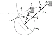
Fig. 1 shows an exemplary embodiment of a wave energy converter 1 of the present invention. The wave energy converter 1 comprises a buoy 2, which buoy 2 can oscillate about a position of equilibrium 4 relative to a reference point 3. The wave energy converter further comprises a negative spring device 10 connected between the buoy 2 and the reference point 3. When the buoy moves away from the equilibrium position 4, the negative spring means 10 exerts a positive force in the displacement direction (z). In the embodiment of fig. 1, the displacement direction (z) is a vertical direction.
In the embodiment of fig. 1, the buoy 2 is spherical and comprises a sealed inflatable enclosure 6, which is generally in the shape of a spherical enclosure. The hull 6 provides buoyancy to the buoy 2. The inner surface 7 of the housing 6 defines a hollow interior 8. The cavity 8 may also provide buoyancy to the buoy 2. The buoy 2 may have a radius of about 4m, but other radii are possible.
The support members 5 (e.g., rods, posts, cables) pass through opposing holes 9 in the housing 6 and through the center of the buoy 2 and are generally oriented in the direction of displacement (z) of the buoy 2. The reference point 3 is fixed to a support member 5 and is positioned in the centre of the buoy 2.
The negative spring means 10 comprises a mechanical coil spring 11 and is fixed between the reference point 3 and the inner surface 7 of the housing 6 such that the negative spring means 10 is perpendicular to the support member 5 and the displacement direction (z) when the buoy 2 is in its equilibrium position 4. When the buoy 2 is in its rest position, the negative spring means 10 is in a state of maximum compression. The connection points 12 and 13 allow the negative spring means 10 to articulate relative to the inner surface 7 and the reference point 3.
Although not shown in fig. 1, the wave energy converter 1 comprises a plurality of negative spring means 10, the spring means 10 extending between the reference point 3 and the inner surface 7 as described above and having substantially the same mechanical properties. A plurality of negative spring means 10 are spaced symmetrically about the axis of the support member 5. The negative spring devices 10 are thus arranged in a star shape, for example a two-pointed star, a three-pointed star or a five-pointed star, around the axis of the support member 5. For example, there may be three negative spring devices 10 spaced at 120 ° angles, all three providing substantially equal forces between the buoy 2 and the support member 5.
It is clear that the buoy 2 in the embodiment of fig. 1 may experience translational/linear motion oscillations due to incoming wave energy. When the buoy 2 is displaced from its equilibrium position 4, the force from the negative spring means 10 has a component in the direction of linear displacement (z). Thus, when the buoy 2 moves away from its equilibrium position, the negative spring means 10 releases its stored energy.
As the buoy 2 moves away from its equilibrium position 4, the amount of force provided by the negative spring arrangement 10 in the displacement direction (z) of the buoy 2 varies. This change in force is due in part to the geometry of the system, since as the displacement of the buoy 2 away from the equilibrium position 4 increases, the z-direction component of the total force exerted by the negative spring arrangement 10 increases relative to the component perpendicular to the z-direction. Furthermore, the total force generated by the negative spring means 10 varies as the length of the negative spring means 10 varies, so that this force varies. Thus, this change in force comes into play when the buoy is displaced from its equilibrium position. The force generated by the negative spring means is used to push the float in an oscillating displacement direction (z). In one example arrangement, the negative spring arrangement 10 may provide a force that initially increases with displacement as the buoy 2 moves away from the equilibrium position 4.
The negative spring means 10 provides a negative stiffness to counter the static stiffness of the buoy 2 and thus reduces the static stiffness of the system. However, for displacements (z) outside the threshold displacement near the equilibrium point, the stiffness of the system is allowed to increase. This can be seen in the example shown in fig. 2, where the dashed line is the static stiffness force (f (z)) of the buoy 2 and the solid line is the force (f (z)) due to the negative spring means 10, both as a function of the displacement (z) from the equilibrium position 4.
The resulting stiffness force of the system is shown in solid lines in fig. 3 (again the dashed lines are the static stiffness force of the buoy 2). It can be seen that the stiffness is reduced near the equilibrium point. It should be noted that the precise values shown on the axes of fig. 2 and 3 and fig. 5, 6, 8, 9 are merely illustrative examples. Greater or lesser displacements and forces may be encountered. These values depend on many factors, including the energy of the incoming waves and the size of the buoy.
As the buoy 2 is displaced from its equilibrium position 4, the total force from the negative spring arrangement decreases. At threshold displacement (marked z in fig. 2) t ) The total force (and therefore the component of the force in the direction of displacement of the float) is zero. As can be seen from FIG. 2, above the threshold displacement (z) t ) The negative spring means 10 provides a force in a direction opposite to the displacement direction (z) of the buoy 2 from its equilibrium position 4. Thus, the negative spring means 10 is displaced in a certain direction (z) t ) Which then acts as a positive spring device and increases the overall stiffness of the system.
Referring to FIG. 2, the total force provided by negative spring assembly 10 initially follows positionThe shift (z) increases with increasing, then shifts (z) at a threshold value t ) Before becoming a positive spring (and thus exerting a force opposite to the direction of displacement). Due to the geometry of the system (similar reasons as described above), the component of the force from the negative spring arrangement in the direction opposite to the direction of displacement of the float may further increase and move since the threshold displacement (z) was exceeded t ) The total force generated by the spring means may then increase as it expands. The positive spring effect at large displacements can be used as part of an "end stop" system that limits the maximum displacement of the float.
Referring to figure 4, there is shown a wave energy converter which is largely similar to that shown in figure 1. However, in this embodiment, each negative spring means 10 may comprise a set of springs 14, the set of springs 14 comprising a pair of V-shaped corner springs arranged symmetrically with respect to a plane perpendicular to the direction of translational movement (z). The set of springs 14 may extend from a connection 13 to the fixed point 3 to a corresponding point 12 on the inner surface 7 of the buoy 2. The respective points 12 are spaced apart in a direction substantially aligned with the direction of the support member 5. In this example embodiment, a gas spring is shown.
As can be seen in fig. 5, the use of the set of springs 14 allows the force characteristics of the negative spring means 10 to be adjusted. In fig. 5, the force on the float in the z-direction from each spring in the set of springs is shown by F1 and F2 (solid lines). The resultant force is shown by Ftot (dashed line). The angle between the springs in each set of springs and the total force generated by each spring (sum F) are selected so that the resultant force from the negative spring arrangement (Fz pneumatic) optimally reduces the static stiffness of the float near the equilibrium point (Fz spherical). This is shown in fig. 6. This angle provides another controllable factor that helps engineers produce the most effective stiffness reduction.
Fig. 7 shows an exemplary embodiment of the invention, in which the buoy 2 undergoes rotational oscillations. The buoy 2 may be substantially similar to the buoy described in relation to the previous embodiment. However, the buoy 2 in the embodiment of fig. 8 only contains one hole 9 to allow the connection member 15 to connect the center of the buoy 2 to the pivot point (a) and one slot (not shown) through which the negative spring means 10 can extend. The buoy 2 oscillates in angular displacement about a pivot point (a) which is outside the buoy 2. A negative spring device 10 may be coupled between the center of the float and the datum 3. When the buoy 2 is displaced from its equilibrium position, the force from the negative spring arrangement has a component in the tangential direction of the oscillating buoy.
The reference point 3 is located along a line extending from the pivot point (a) in the direction of the equilibrium angle of the buoy. Furthermore, it is positioned between the centre of the buoy 2 when it is in its equilibrium position to the pivot point (a).
The negative spring assembly 10 of the wave energy converter 1 of fig. 7 acts similarly to the negative spring assembly 10 of fig. 1 to 4 to reduce the static stiffness of the system and thus increase the bandwidth of the wave energy converter. The reduction in static stiffness can be seen in fig. 8 and 9, which show similar effects to fig. 2 and 3. Thus, in fig. 8, the dashed line is the static stiffness moment (τ (θ)) of the buoy 2, while the solid line is the moment (τ (θ)) due to the negative spring arrangement 10, which is a function of the angular displacement (θ) from the equilibrium point 4. The resulting moment of stiffness of the system (τ (θ)) is shown by the solid line in fig. 9 (again the dashed line is the moment of static stiffness of the buoy 2). It can be seen that the stiffness is reduced near the point of equilibrium.
As mentioned above, the effect of the negative spring is to greatly increase the energy that the system can deliver. For a linear oscillating buoy of the type shown in fig. 4, it has been found that the energy transfer is improved by at least 100% compared to a standard buoy design. This experiment used a conventional resistive load device to measure energy transfer. Thus, a significant advantage provided by the wave energy converter described herein is at least a doubled average power output compared to known designs.
Claims (26)
1. A wave energy converter for extracting energy from ocean waves, comprising:
a buoy arranged to oscillate about an equilibrium position relative to a datum; and
a negative spring device connected between the float and the reference point, wherein the negative spring device is configured to provide a positive force in a displacement direction when the float moves away from the equilibrium position, wherein the negative spring device comprises a plurality of mechanical springs;
the buoy comprising a sealed, gas filled housing, wherein an inner surface of the sealed, gas filled housing defines a hollow interior cavity and the reference point is positioned at a center of the buoy;
wherein the negative spring means is secured between the datum point and an inner surface of the sealed, gas-filled enclosure;
wherein the negative spring arrangement exerts a positive force in a displacement direction when the float moves away from the equilibrium position;
wherein the negative spring arrangement is configured to provide no force in the direction of oscillatory movement of the float when the float is in its equilibrium position.
2. A wave energy convertor as claimed in claim 1, wherein the negative spring device is configured to provide a force that initially increases with displacement as the buoy moves away from the equilibrium position.
3. A wave energy convertor as claimed in claim 1, wherein the negative spring device acts to counteract a static stiffness of the buoy when the buoy is in use, such that the overall stiffness of the buoy in the equilibrium position is reduced compared to a buoy without a negative spring.
4. A wec according to claim 3, wherein the overall stiffness of the float in the equilibrium position is at least 4/5 lower than a float without a negative spring.
5. A wave energy convertor as claimed in claim 1, wherein the negative spring device acts, in use, to counteract a static stiffness of the buoy, so as to thereby increase a resonant oscillation bandwidth of the buoy.
6. A wave energy convertor as claimed in claim 1, wherein at displacements greater than a threshold displacement, the negative spring device provides a force having a component in a direction opposite to the direction of displacement of the float from its equilibrium position.
7. A WEC according to claim 6, wherein said negative spring means is configured such that said component of said force in a direction opposite to the displacement direction of the float increases with increasing displacement of the float beyond said threshold displacement.
8. A wec according to claim 1, wherein the mechanical spring is a coil spring or a gas spring.
9. A wave energy convertor as claimed in claim 1, comprising a plurality of negative spring devices.
10. A wec according to claim 9, wherein the plurality of negative spring means extend in different directions along a plane perpendicular to the direction of motion at the equilibrium position.
11. A wec according to claim 10, wherein the plurality of negative spring means are arranged symmetrically.
12. A wave energy converter according to claim 1, wherein the plurality of mechanical springs comprises a pair of V-shaped angle springs arranged symmetrically about a direction perpendicular to the direction of motion at the equilibrium position and lying on the same plane as the direction of motion and its perpendicular direction.
13. A wave energy convertor as claimed in claim 1, wherein the reference point is provided on a support member, the buoy being configured to oscillate relative to the support member.
14. A wec according to claim 13, wherein the buoy is configured to undergo translational/linear motion oscillations.
15. A wec according to claim 14, wherein the support member passes through the centre of the buoy.
16. A wec according to claim 14 or 15, wherein the support member is oriented in the direction of linear oscillation of the buoy.
17. A wec according to claim 13, wherein the buoy is configured for rotational oscillation in an angular displacement about a pivot point external to the buoy.
18. A wec according to claim 13, wherein the negative spring means is coupled between the centre of the float and the reference point.
19. A wec according to claim 17, wherein the reference point is located at or near any position along a line connecting the equilibrium position and the pivot point.
20. A method of extracting energy from ocean waves, comprising:
allowing the buoy to oscillate about an equilibrium position relative to a datum due to wave motion; and
providing a positive force between the float and the datum when the float moves away from the equilibrium position using a negative spring arrangement, the positive force being in the direction of displacement between the float and the equilibrium position, wherein the negative spring arrangement comprises a plurality of mechanical springs;
the buoy comprising a sealed, gas filled housing, wherein an inner surface of the sealed, gas filled housing defines a hollow interior cavity and the reference point is positioned at a center of the buoy;
wherein the negative spring means is secured between the datum point and an inner surface of the sealed, gas-filled enclosure;
wherein the negative spring arrangement exerts a positive force in a displacement direction when the float moves away from the equilibrium position;
wherein the negative spring arrangement is configured to provide no force in the direction of oscillatory movement of the float when the float is in its equilibrium position.
21. The method of claim 20, comprising: when the displacement is greater than a threshold displacement, a positive force is provided between the float and the datum in a direction opposite to the direction of displacement between the float and its equilibrium position.
22. The method of claim 20 or 21, wherein the negative spring arrangement is used to counteract the static stiffness of the buoy such that the overall stiffness of the buoy at the equilibrium position is reduced compared to a buoy without a negative spring.
23. The method of claim 22, wherein the overall stiffness of the float at the equilibrium position is at least 4/5 lower than a float without a negative spring.
24. The method of claim 20, wherein the negative spring device is used to counteract a static stiffness of the buoy to thereby increase a resonant oscillation bandwidth of the buoy.
25. A method according to claim 20, wherein the force between the float and the reference point is provided by a negative spring device of a wave energy convertor as claimed in any of claims 1 to 19.
26. A wave energy convertor for use in a method according to any one of claims 20 to 25, the wave energy convertor comprising a buoy connected to a reference point by a negative spring device.
Applications Claiming Priority (3)
| Application Number | Priority Date | Filing Date | Title |
|---|---|---|---|
| GB1400906.2A GB2522251B (en) | 2014-01-20 | 2014-01-20 | Wave energy convertor |
| GB1400906.2 | 2014-01-20 | ||
| PCT/EP2015/050794 WO2015107158A1 (en) | 2014-01-20 | 2015-01-16 | Wave energy convertor |
Publications (2)
| Publication Number | Publication Date |
|---|---|
| CN106170624A CN106170624A (en) | 2016-11-30 |
| CN106170624B true CN106170624B (en) | 2022-09-20 |
Family
ID=50239167
Family Applications (1)
| Application Number | Title | Priority Date | Filing Date |
|---|---|---|---|
| CN201580005072.8A Active CN106170624B (en) | 2014-01-20 | 2015-01-16 | Wave energy converter |
Country Status (13)
| Country | Link |
|---|---|
| US (2) | US10082127B2 (en) |
| EP (1) | EP3102818B1 (en) |
| JP (1) | JP6572238B2 (en) |
| KR (1) | KR102143265B1 (en) |
| CN (1) | CN106170624B (en) |
| AU (1) | AU2015207492B2 (en) |
| CA (1) | CA2936013C (en) |
| CL (1) | CL2016001818A1 (en) |
| DK (1) | DK3102818T3 (en) |
| ES (1) | ES2808848T3 (en) |
| GB (1) | GB2522251B (en) |
| PT (1) | PT3102818T (en) |
| WO (1) | WO2015107158A1 (en) |
Families Citing this family (3)
| Publication number | Priority date | Publication date | Assignee | Title |
|---|---|---|---|---|
| EP3456956A1 (en) | 2017-09-16 | 2019-03-20 | Corpower Ocean AB | Method of controlling a wave energy converter and such a wave energy converter |
| CN108119294A (en) * | 2017-12-14 | 2018-06-05 | 上海交通大学 | A kind of spring bistable directly drives float type wave energy power generation |
| JP7281210B2 (en) * | 2018-02-07 | 2023-05-25 | サイモン メディカル アーエス | ultrasound blood flow monitoring |
Citations (7)
| Publication number | Priority date | Publication date | Assignee | Title |
|---|---|---|---|---|
| US4134023A (en) * | 1976-01-20 | 1979-01-09 | The Secretary Of State For Energy In Her Britannic Majesty's Government Of The United Kingdom Of Great Britain And Northern Ireland | Apparatus for use in the extraction of energy from waves on water |
| CN1878952A (en) * | 2003-10-14 | 2006-12-13 | 星浪能量公司 | A wave power apparatus having a float and means for locking the float in a position above the ocean surface |
| CN101526062A (en) * | 2008-03-08 | 2009-09-09 | 曲言明 | Floating body rope pulley wave energy generating system |
| CN101715513A (en) * | 2007-04-18 | 2010-05-26 | 技术源于思维有限公司 | Damper and damping structure for a wave energy conversion device |
| CN102808719A (en) * | 2012-08-15 | 2012-12-05 | 天津大学 | Float transaction wave power generating device |
| CN103075293A (en) * | 2013-01-14 | 2013-05-01 | 集美大学 | Cylindrical floating body type wave power generation device |
| US8629572B1 (en) * | 2012-10-29 | 2014-01-14 | Reed E. Phillips | Linear faraday induction generator for the generation of electrical power from ocean wave kinetic energy and arrangements thereof |
Family Cites Families (13)
| Publication number | Priority date | Publication date | Assignee | Title |
|---|---|---|---|---|
| GB1316950A (en) * | 1969-06-30 | 1973-05-16 | Univ North Wales | Electric generator |
| NO140231C (en) * | 1977-11-11 | 1979-07-25 | Einar Jakobsen | WAVE ENGINE FOR BOAT PROPULSION |
| NO143308C (en) * | 1979-04-04 | 1981-01-14 | Einar Jakobsen | SHELTER ENGINE, SPECIFIC FOR BATHER PROGRESS. |
| NL8301460A (en) | 1983-04-26 | 1984-11-16 | Philips Nv | ELECTROACOUSTIC CONVERTER UNIT WITH REDUCED RESONANCE FREQUENCY. |
| US7305823B2 (en) * | 2004-01-14 | 2007-12-11 | Ocean Power Technologies, Inc | Active impedance matching systems and methods for wave energy converter |
| AU2006320515C1 (en) * | 2005-12-01 | 2012-03-01 | Ocean Power Technologies, Inc. | Wave energy converter utilizing internal reaction mass and spring |
| US7538445B2 (en) * | 2006-05-05 | 2009-05-26 | Sri International | Wave powered generation |
| BRPI1004764B1 (en) * | 2010-11-04 | 2020-07-28 | Marcelo Regattieri Sampaio | wave power converter |
| JP6050311B2 (en) * | 2011-03-28 | 2016-12-21 | オーシャン パワー テクノロジーズ,インク. | Multimode wave energy converter device and system |
| JP6133844B2 (en) | 2011-03-28 | 2017-05-24 | オーシャン パワー テクノロジーズ,インク. | Wave energy converter with rotary fluid spring |
| ITTO20110879A1 (en) * | 2011-10-03 | 2013-04-04 | Noomen Technologies S R L | ELECTRIC POWER GENERATOR SYSTEM FROM THE SEA MOTO MOTION |
| GB201210133D0 (en) * | 2012-06-08 | 2012-07-25 | Univ Manchester | Wave energy converter |
| US8763389B2 (en) * | 2012-07-05 | 2014-07-01 | Ocean Power Technologies, Inc. | Reaction mass and spring oscillator for wave energy converter |
-
2014
- 2014-01-20 GB GB1400906.2A patent/GB2522251B/en active Active
-
2015
- 2015-01-16 KR KR1020167022864A patent/KR102143265B1/en active IP Right Grant
- 2015-01-16 EP EP15700584.4A patent/EP3102818B1/en active Active
- 2015-01-16 WO PCT/EP2015/050794 patent/WO2015107158A1/en active Application Filing
- 2015-01-16 AU AU2015207492A patent/AU2015207492B2/en active Active
- 2015-01-16 CN CN201580005072.8A patent/CN106170624B/en active Active
- 2015-01-16 DK DK15700584.4T patent/DK3102818T3/en active
- 2015-01-16 PT PT157005844T patent/PT3102818T/en unknown
- 2015-01-16 CA CA2936013A patent/CA2936013C/en active Active
- 2015-01-16 ES ES15700584T patent/ES2808848T3/en active Active
- 2015-01-16 JP JP2016564402A patent/JP6572238B2/en active Active
- 2015-01-16 US US15/111,659 patent/US10082127B2/en active Active
-
2016
- 2016-07-18 CL CL2016001818A patent/CL2016001818A1/en unknown
-
2018
- 2018-08-22 US US16/108,287 patent/US20180355836A1/en not_active Abandoned
Patent Citations (7)
| Publication number | Priority date | Publication date | Assignee | Title |
|---|---|---|---|---|
| US4134023A (en) * | 1976-01-20 | 1979-01-09 | The Secretary Of State For Energy In Her Britannic Majesty's Government Of The United Kingdom Of Great Britain And Northern Ireland | Apparatus for use in the extraction of energy from waves on water |
| CN1878952A (en) * | 2003-10-14 | 2006-12-13 | 星浪能量公司 | A wave power apparatus having a float and means for locking the float in a position above the ocean surface |
| CN101715513A (en) * | 2007-04-18 | 2010-05-26 | 技术源于思维有限公司 | Damper and damping structure for a wave energy conversion device |
| CN101526062A (en) * | 2008-03-08 | 2009-09-09 | 曲言明 | Floating body rope pulley wave energy generating system |
| CN102808719A (en) * | 2012-08-15 | 2012-12-05 | 天津大学 | Float transaction wave power generating device |
| US8629572B1 (en) * | 2012-10-29 | 2014-01-14 | Reed E. Phillips | Linear faraday induction generator for the generation of electrical power from ocean wave kinetic energy and arrangements thereof |
| CN103075293A (en) * | 2013-01-14 | 2013-05-01 | 集美大学 | Cylindrical floating body type wave power generation device |
Also Published As
| Publication number | Publication date |
|---|---|
| AU2015207492B2 (en) | 2018-02-01 |
| JP6572238B2 (en) | 2019-09-04 |
| WO2015107158A1 (en) | 2015-07-23 |
| PT3102818T (en) | 2020-08-20 |
| EP3102818A1 (en) | 2016-12-14 |
| GB2522251B (en) | 2020-05-06 |
| KR20160128312A (en) | 2016-11-07 |
| DK3102818T3 (en) | 2020-08-03 |
| CA2936013A1 (en) | 2015-07-23 |
| US20180355836A1 (en) | 2018-12-13 |
| CN106170624A (en) | 2016-11-30 |
| AU2015207492A1 (en) | 2016-07-28 |
| GB201400906D0 (en) | 2014-03-05 |
| US10082127B2 (en) | 2018-09-25 |
| KR102143265B1 (en) | 2020-08-11 |
| CL2016001818A1 (en) | 2016-12-09 |
| GB2522251A (en) | 2015-07-22 |
| US20160333846A1 (en) | 2016-11-17 |
| EP3102818B1 (en) | 2020-06-03 |
| JP2017503116A (en) | 2017-01-26 |
| ES2808848T3 (en) | 2021-03-02 |
| CA2936013C (en) | 2023-06-27 |
Similar Documents
| Publication | Publication Date | Title |
|---|---|---|
| EP2256337B1 (en) | Wave energy generator | |
| Vicente et al. | Nonlinear dynamics of a tightly moored point-absorber wave energy converter | |
| JP4996680B2 (en) | Wave energy converter | |
| US11279452B2 (en) | Motion absorbing system and method for a structure | |
| US8134281B2 (en) | Electrical generators for use in unmoored buoys and the like platforms with low-frequency and time-varying oscillatory motions | |
| CN106170624B (en) | Wave energy converter | |
| EP2496828A2 (en) | Wave energy conversion device | |
| Viet et al. | A novel heaving ocean wave energy harvester with a frequency tuning capability | |
| CN112204195A (en) | Protective device | |
| JP6612770B2 (en) | Wave energy converter | |
| KR20190017276A (en) | Movement reducing apparatus of floating offshore structure | |
| Bracco et al. | ISWEC: Design of a prototype model for wave tank test | |
| EP4086159A2 (en) | Motion absorbing system and method for a structure | |
| Vicente et al. | Nonlinear dynamics of a floating wave energy converter reacting against the sea bottom through a tight mooring cable | |
| US20220242529A1 (en) | A buoyant rotatable marine transducer | |
| EP2657511A1 (en) | Water wave energy converter | |
| GB2489268A (en) | Cyclic to rotary motion converter |
Legal Events
| Date | Code | Title | Description |
|---|---|---|---|
| C06 | Publication | ||
| PB01 | Publication | ||
| C10 | Entry into substantive examination | ||
| SE01 | Entry into force of request for substantive examination | ||
| GR01 | Patent grant | ||
| GR01 | Patent grant |