EP4563807A1 - Air inlet assembly of engine, engine, and vehicle - Google Patents
Air inlet assembly of engine, engine, and vehicle Download PDFInfo
- Publication number
- EP4563807A1 EP4563807A1 EP23845063.9A EP23845063A EP4563807A1 EP 4563807 A1 EP4563807 A1 EP 4563807A1 EP 23845063 A EP23845063 A EP 23845063A EP 4563807 A1 EP4563807 A1 EP 4563807A1
- Authority
- EP
- European Patent Office
- Prior art keywords
- air inlet
- section
- cavity
- air outlet
- air
- Prior art date
- Legal status (The legal status is an assumption and is not a legal conclusion. Google has not performed a legal analysis and makes no representation as to the accuracy of the status listed.)
- Pending
Links
Images


Classifications
-
- F—MECHANICAL ENGINEERING; LIGHTING; HEATING; WEAPONS; BLASTING
- F02—COMBUSTION ENGINES; HOT-GAS OR COMBUSTION-PRODUCT ENGINE PLANTS
- F02B—INTERNAL-COMBUSTION PISTON ENGINES; COMBUSTION ENGINES IN GENERAL
- F02B29/00—Engines characterised by provision for charging or scavenging not provided for in groups F02B25/00, F02B27/00 or F02B33/00 - F02B39/00; Details thereof
- F02B29/04—Cooling of air intake supply
- F02B29/045—Constructional details of the heat exchangers, e.g. pipes, plates, ribs, insulation, materials, or manufacturing and assembly
- F02B29/0468—Water separation or drainage means
-
- F—MECHANICAL ENGINEERING; LIGHTING; HEATING; WEAPONS; BLASTING
- F02—COMBUSTION ENGINES; HOT-GAS OR COMBUSTION-PRODUCT ENGINE PLANTS
- F02B—INTERNAL-COMBUSTION PISTON ENGINES; COMBUSTION ENGINES IN GENERAL
- F02B29/00—Engines characterised by provision for charging or scavenging not provided for in groups F02B25/00, F02B27/00 or F02B33/00 - F02B39/00; Details thereof
- F02B29/04—Cooling of air intake supply
- F02B29/0406—Layout of the intake air cooling or coolant circuit
- F02B29/0425—Air cooled heat exchangers
-
- F—MECHANICAL ENGINEERING; LIGHTING; HEATING; WEAPONS; BLASTING
- F02—COMBUSTION ENGINES; HOT-GAS OR COMBUSTION-PRODUCT ENGINE PLANTS
- F02B—INTERNAL-COMBUSTION PISTON ENGINES; COMBUSTION ENGINES IN GENERAL
- F02B29/00—Engines characterised by provision for charging or scavenging not provided for in groups F02B25/00, F02B27/00 or F02B33/00 - F02B39/00; Details thereof
- F02B29/04—Cooling of air intake supply
- F02B29/0406—Layout of the intake air cooling or coolant circuit
- F02B29/0437—Liquid cooled heat exchangers
-
- F—MECHANICAL ENGINEERING; LIGHTING; HEATING; WEAPONS; BLASTING
- F02—COMBUSTION ENGINES; HOT-GAS OR COMBUSTION-PRODUCT ENGINE PLANTS
- F02B—INTERNAL-COMBUSTION PISTON ENGINES; COMBUSTION ENGINES IN GENERAL
- F02B29/00—Engines characterised by provision for charging or scavenging not provided for in groups F02B25/00, F02B27/00 or F02B33/00 - F02B39/00; Details thereof
- F02B29/04—Cooling of air intake supply
- F02B29/045—Constructional details of the heat exchangers, e.g. pipes, plates, ribs, insulation, materials, or manufacturing and assembly
- F02B29/0462—Liquid cooled heat exchangers
-
- F—MECHANICAL ENGINEERING; LIGHTING; HEATING; WEAPONS; BLASTING
- F02—COMBUSTION ENGINES; HOT-GAS OR COMBUSTION-PRODUCT ENGINE PLANTS
- F02B—INTERNAL-COMBUSTION PISTON ENGINES; COMBUSTION ENGINES IN GENERAL
- F02B29/00—Engines characterised by provision for charging or scavenging not provided for in groups F02B25/00, F02B27/00 or F02B33/00 - F02B39/00; Details thereof
- F02B29/04—Cooling of air intake supply
- F02B29/045—Constructional details of the heat exchangers, e.g. pipes, plates, ribs, insulation, materials, or manufacturing and assembly
- F02B29/0475—Constructional details of the heat exchangers, e.g. pipes, plates, ribs, insulation, materials, or manufacturing and assembly the intake air cooler being combined with another device, e.g. heater, valve, compressor, filter or EGR cooler, or being assembled on a special engine location
-
- F—MECHANICAL ENGINEERING; LIGHTING; HEATING; WEAPONS; BLASTING
- F02—COMBUSTION ENGINES; HOT-GAS OR COMBUSTION-PRODUCT ENGINE PLANTS
- F02B—INTERNAL-COMBUSTION PISTON ENGINES; COMBUSTION ENGINES IN GENERAL
- F02B33/00—Engines characterised by provision of pumps for charging or scavenging
- F02B33/32—Engines with pumps other than of reciprocating-piston type
- F02B33/34—Engines with pumps other than of reciprocating-piston type with rotary pumps
- F02B33/40—Engines with pumps other than of reciprocating-piston type with rotary pumps of non-positive-displacement type
-
- F—MECHANICAL ENGINEERING; LIGHTING; HEATING; WEAPONS; BLASTING
- F02—COMBUSTION ENGINES; HOT-GAS OR COMBUSTION-PRODUCT ENGINE PLANTS
- F02D—CONTROLLING COMBUSTION ENGINES
- F02D9/00—Controlling engines by throttling air or fuel-and-air induction conduits or exhaust conduits
- F02D9/02—Controlling engines by throttling air or fuel-and-air induction conduits or exhaust conduits concerning induction conduits
-
- F—MECHANICAL ENGINEERING; LIGHTING; HEATING; WEAPONS; BLASTING
- F02—COMBUSTION ENGINES; HOT-GAS OR COMBUSTION-PRODUCT ENGINE PLANTS
- F02M—SUPPLYING COMBUSTION ENGINES IN GENERAL WITH COMBUSTIBLE MIXTURES OR CONSTITUENTS THEREOF
- F02M31/00—Apparatus for thermally treating combustion-air, fuel, or fuel-air mixture
- F02M31/20—Apparatus for thermally treating combustion-air, fuel, or fuel-air mixture for cooling
-
- F—MECHANICAL ENGINEERING; LIGHTING; HEATING; WEAPONS; BLASTING
- F02—COMBUSTION ENGINES; HOT-GAS OR COMBUSTION-PRODUCT ENGINE PLANTS
- F02M—SUPPLYING COMBUSTION ENGINES IN GENERAL WITH COMBUSTIBLE MIXTURES OR CONSTITUENTS THEREOF
- F02M35/00—Combustion-air cleaners, air intakes, intake silencers, or induction systems specially adapted for, or arranged on, internal-combustion engines
- F02M35/10—Air intakes; Induction systems
- F02M35/1015—Air intakes; Induction systems characterised by the engine type
- F02M35/10157—Supercharged engines
-
- F—MECHANICAL ENGINEERING; LIGHTING; HEATING; WEAPONS; BLASTING
- F02—COMBUSTION ENGINES; HOT-GAS OR COMBUSTION-PRODUCT ENGINE PLANTS
- F02M—SUPPLYING COMBUSTION ENGINES IN GENERAL WITH COMBUSTIBLE MIXTURES OR CONSTITUENTS THEREOF
- F02M35/00—Combustion-air cleaners, air intakes, intake silencers, or induction systems specially adapted for, or arranged on, internal-combustion engines
- F02M35/10—Air intakes; Induction systems
- F02M35/10242—Devices or means connected to or integrated into air intakes; Air intakes combined with other engine or vehicle parts
- F02M35/10255—Arrangements of valves; Multi-way valves
-
- F—MECHANICAL ENGINEERING; LIGHTING; HEATING; WEAPONS; BLASTING
- F02—COMBUSTION ENGINES; HOT-GAS OR COMBUSTION-PRODUCT ENGINE PLANTS
- F02M—SUPPLYING COMBUSTION ENGINES IN GENERAL WITH COMBUSTIBLE MIXTURES OR CONSTITUENTS THEREOF
- F02M35/00—Combustion-air cleaners, air intakes, intake silencers, or induction systems specially adapted for, or arranged on, internal-combustion engines
- F02M35/10—Air intakes; Induction systems
- F02M35/10242—Devices or means connected to or integrated into air intakes; Air intakes combined with other engine or vehicle parts
- F02M35/10262—Flow guides, obstructions, deflectors or the like
-
- F—MECHANICAL ENGINEERING; LIGHTING; HEATING; WEAPONS; BLASTING
- F02—COMBUSTION ENGINES; HOT-GAS OR COMBUSTION-PRODUCT ENGINE PLANTS
- F02M—SUPPLYING COMBUSTION ENGINES IN GENERAL WITH COMBUSTIBLE MIXTURES OR CONSTITUENTS THEREOF
- F02M35/00—Combustion-air cleaners, air intakes, intake silencers, or induction systems specially adapted for, or arranged on, internal-combustion engines
- F02M35/10—Air intakes; Induction systems
- F02M35/104—Intake manifolds
-
- Y—GENERAL TAGGING OF NEW TECHNOLOGICAL DEVELOPMENTS; GENERAL TAGGING OF CROSS-SECTIONAL TECHNOLOGIES SPANNING OVER SEVERAL SECTIONS OF THE IPC; TECHNICAL SUBJECTS COVERED BY FORMER USPC CROSS-REFERENCE ART COLLECTIONS [XRACs] AND DIGESTS
- Y02—TECHNOLOGIES OR APPLICATIONS FOR MITIGATION OR ADAPTATION AGAINST CLIMATE CHANGE
- Y02T—CLIMATE CHANGE MITIGATION TECHNOLOGIES RELATED TO TRANSPORTATION
- Y02T10/00—Road transport of goods or passengers
- Y02T10/10—Internal combustion engine [ICE] based vehicles
- Y02T10/12—Improving ICE efficiencies
Definitions
- the present disclosure relates to the field of vehicle power technologies, and specifically, to an air inlet assembly of an engine, an engine, and a vehicle.
- the engine compartment space of an overall vehicle is limited, and therefore the arrangement requirements of an air inlet system of the supercharged engine are particularly strict.
- the characteristic of the air inflow of the supercharged engine lies in that after fresh air undergoes compression work performed by the supercharger, the temperature of gas rises sharply, which may generally reach a maximum of about 150°C. If the gas is not cooled, an actual air inflow amount of the engine is small, which affects a supercharging effect and emission. Therefore, the air inflow of the supercharged engine generally requires cooling through the intercooler.
- a high-performance supercharged direct-injection gasoline engine has a high requirement on a cooling capacity of an intercooler.
- the oversized intercooler and air inlet manifold occupy a significant amount of space, making it difficult to arrange them in an engine compartment with a limited space, which also affects arrangement design of other components in the engine compartment.
- the present disclosure is intended to resolve at least one of technical problems existing in the related art. Accordingly, the present disclosure provides an air inlet assembly of an engine.
- the air inlet assembly of an engine has advantages such as low costs, a small volume, and convenient mounting.
- the present disclosure further provides an engine having the foregoing air inlet assembly.
- the present disclosure further provides a vehicle having the foregoing engine.
- An air inlet assembly of an engine includes: an air inlet manifold; an intercooler, where the intercooler having a first air inlet and an air outlet, and the air outlet is directly attached to and in communication with the air inlet manifold; and a throttle valve, where the throttle valve is arranged on the first air inlet to control an air inflow amount.
- the air inlet assembly according to the embodiments of the present disclosure has advantages such as low costs, a small volume, and convenient mounting.
- the intercooler includes: an intercooler body; an air inlet cavity and an air outlet cavity, where the intercooler body is arranged between the air inlet cavity and the air outlet cavity and respectively in communication with the air inlet cavity and the air outlet cavity, the first air inlet is opened on the air inlet cavity, and the air outlet is opened on the air outlet cavity.
- a gas storage capacity of the intercooler body is V1, and V1 satisfies a relation formula: 1200 ml ⁇ V1 ⁇ 1300 ml.
- the air inlet cavity is arranged with a first air inlet section, a second air inlet section, and a third air inlet section that are sequentially in communication, the first air inlet section is in communication with the first air inlet, and the third air inlet section is in communication with the intercooler body, to uniformly guide gas into the intercooler body.
- a cross-sectional area of the third air inlet section is greater than a cross-sectional area of the first air inlet section, and a cross-sectional area of the second air inlet section gradually increases from the first air inlet section to the third air inlet section.
- a spacing between a front side wall and a rear side wall of the second air inlet section gradually increases from right to left, an angle between the front side wall and the rear side wall of the second air inlet section is ⁇ , and ⁇ satisfies a relation formula: 50° ⁇ ⁇ ⁇ 70°.
- the air outlet cavity is arranged with a first air outlet section, a second air outlet section, and a third air outlet section that are sequentially in communication, the first air outlet section is in communication with the air outlet, and the third air outlet section is in communication with the intercooler body, to uniformly guide gas into the air inlet manifold.
- a cross-sectional area of the third air outlet section is less than a cross-sectional area of the first air outlet section, and a cross-sectional area of the second air outlet section gradually decreases from the first air outlet section to the third air outlet section.
- a spacing between a front side wall and a rear side wall of the second air outlet section gradually decreases from right to left, an angle between the rear side wall of the second air outlet section and a cross-section of the air outlet cavity is ⁇ , and ⁇ satisfies a relation formula: 20° ⁇ ⁇ ⁇ 40°.
- a spacing between an upper side wall and a lower side wall of the second air outlet section gradually decreases from right to left, an angle between the upper side wall and the lower side wall of the second air outlet section is ⁇ , and ⁇ satisfies a relation formula: 25° ⁇ ⁇ ⁇ 35°.
- multiple reinforcing ribs are arranged on outer walls of the air inlet cavity and/or the air outlet cavity, and the multiple reinforcing ribs are distributed in a staggered manner.
- the intercooler body is arranged with a cooling channel, and the intercooler body is arranged with a water inlet pipe connector in communication with one end of the cooling channel and a water outlet pipe connector in communication with another end of the cooling channel.
- the air inlet manifold is arranged with a pressure stabilizing cavity and an air inlet passage, one end of the air inlet passage is in communication with the pressure stabilizing cavity, another end of the air inlet passage is in communication with an engine cylinder block, a bottom wall of the air inlet passage includes a first wall section, the first wall section is connected to a bottom wall of the pressure stabilizing cavity and is arranged obliquely downward with respect to the bottom wall of the pressure stabilizing cavity, an angle ⁇ is formed between the first wall section and the bottom wall of the pressure stabilizing cavity, and 2° ⁇ ⁇ ⁇ 5°.
- the bottom wall of the air inlet passage further includes: a second wall section, where the second wall section is connected to a side of the first wall section away from the pressure stabilizing cavity, the second wall section is arranged obliquely downward with respect to the first wall section, an angle ⁇ is formed between the second wall section and the first wall section, and 24° ⁇ ⁇ ⁇ 26°.
- a volume of the pressure stabilizing cavity is V2, and V2 satisfies a relation formula: 1 L ⁇ V2 ⁇ 1.2 L.
- a length of the air inlet passage is L, and L satisfies a relation formula: 70 mm ⁇ L ⁇ 80 mm.
- the pressure stabilizing cavity is arranged with: an impact separation piece, where the impact separation piece is located in the pressure stabilizing cavity, to impact entering gas to reduce generation of condensed water; and a flow guiding piece, where the flow guiding piece is arranged in the pressure stabilizing cavity, to guide condensed water in the pressure stabilizing cavity to the air inlet passage.
- the impact separation piece is an impact grid
- the pressure stabilizing cavity is arranged with a second air inlet
- the impact grid corresponds to the second air inlet, to impact entering gas to reduce generation of condensed water
- the flow guiding piece includes multiple flow guiding baffles, multiple air inlet passages are provided, each of the multiple flow guiding baffles extends toward the air inlet passages, and the multiple flow guiding baffles guide condensed water in the pressure stabilizing cavity to the multiple air inlet passages.
- an engine including: engine cylinder block; a cylinder head, where the cylinder head covers above the engine cylinder block, and a mounting bracket is arranged on the cylinder head; and the air inlet assembly of an engine according to the embodiments of the first aspect of the present disclosure.
- the intercooler is located above the air inlet manifold, and the mounting bracket is fixedly connected to the intercooler and/or the throttle valve.
- the engine according to embodiments of the second aspect of the present disclosure has advantages such as low costs, a small volume, and convenient mounting.
- a vehicle including the engine according to the embodiments of the second aspect of the present disclosure.
- the vehicle according to the embodiments of the third aspect of the present disclosure has advantages such as low costs, a small volume, and convenient mounting.
- orientations or position relationships indicated by terms such as “center”, “longitudinal”, “transverse”, “length”, “width”, “thickness”, “up”, “down”, “front”, “rear”, “left”, “right”, “vertical”, “horizontal”, “top”, “bottom”, “inner”, “outer”, “clockwise”, “counterclockwise”, “axial”, “radial”, and “circumferential” are orientations or position relationship shown based on the accompanying drawings, and are merely used for describing the present disclosure and simplifying the description, rather than indicating or implying that the apparatus or element should have a particular orientation or be constructed and operated in a particular orientation, and therefore, should not be construed as a limitation on the present disclosure.
- a "first feature” and a “second feature” may include one or more such features.
- the air inlet assembly 1 of an engine includes an air inlet manifold 100, an intercooler 200, and a throttle valve 300.
- the intercooler 200 has a first air inlet 210 and an air outlet 220.
- the air outlet 220 is directly attached to and in communication with the air inlet manifold 100.
- the throttle valve 300 is arranged on the first air inlet 210.
- the temperature of exhaust discharged by an engine is very high, and the temperature of entering gas is increased due to the pressure increasing of a supercharger.
- the density of the air increases, and further the temperature of air discharged by the supercharger increases.
- the density of oxygen decreases, which greatly affects the combustion effective efficiency of the engine.
- high-temperature air from the supercharger is cooled by using the intercooler 200, and the air cooled by the intercooler 200 enters an engine cylinder block through the air inlet manifold 100 and is mixed with fuel for combustion to release energy, so that thermal load of the engine 2 can be greatly reduced, to improve an air inflow amount of the engine 2, thereby improving the combustion effective efficiency of the engine 2, and improving the power performance of a vehicle.
- the air outlet 220 of the intercooler 200 is directly attached to and in communication with the air inlet manifold 100, so that the structure formed by the intercooler 200 and the air inlet manifold 100 has a high integration level, and an air guide pipe between the intercooler 200 and the air inlet manifold 100 is omitted.
- This is conducive to saving materials and further reducing costs.
- an overall volume of the air inlet assembly 1 of an engine can be smaller, which is more conducive to arranging the intercooler 200 in an engine compartment of the engine 2 with a limited space, thereby improving mounting convenience.
- the throttle valve 300 is arranged on the first air inlet 210 to control an air inflow amount.
- an amount of gas that enters the intercooler 200 can be precisely controlled, so that the air inflow amount of the intercooler 200 is almost a required amount of the engine, and it can be ensured that air that enters the air inlet manifold 100 can be fully burned, thereby ensuring the combustion effective efficiency of the engine, and greatly reducing fuel consumption.
- the air inlet assembly 1 of an engine in the present disclosure can control the air inflow amount of the intercooler 200 through the throttle valve 300 according to different operating conditions and different air inflow amount requirements of the engine 2, so that different requirements can be met.
- an amount of gas that needs to be cooled by the intercooler 200 is reduced, so that the volume of the intercooler 200 can be effectively reduced, making the arrangement of the entire engine compartment compact, a space arrangement requirement of a small engine compartment can be met, and great convenience is provided for the freedom of overall vehicle design.
- the throttle valve 300 is arranged on the first air inlet 210, and it is not necessary to additionally arrange an air guide pipe between the air outlet 220 of the intercooler 200 and the air inlet manifold 100 to fix the throttle valve 300, so that an air guide pipe between the air outlet 220 of the intercooler 200 and the air inlet manifold 100 is not required.
- the throttle valve 300 is arranged on the first air inlet 210, so that an overall height is not increased, which is conducive to space arrangement.
- the air inflow amount of the intercooler 200 can be adjusted to adequately meet an air inflow amount required by the engine 2. In this way, a problem of wasting an internal space of the intercooler 200 is avoided, so that the volume of the intercooler 200 is relatively small for better matching and arrangement in the compartment of the engine 2.
- the air inlet assembly according to the embodiments of the present disclosure has advantages such as low costs, a small volume, and convenient mounting.
- the air inlet assembly 1 of an engine in the embodiments of the present disclosure has the following beneficial effects:
- the required air inflow amount of the engine 2 is almost an amount of gas entering the intercooler 200, so that it can be ensured that the gas entering the air inlet manifold 100 is fully burnt in the engine cylinder block 800.
- the intercooler 200 is arranged with the throttle valve 300 on the first air inlet 210, so that the amount of gas that needs to be cooled by the intercooler 200 is relatively reduced, and the volume of the intercooler 200 is reduced to be applicable to an arrangement in which the space of the engine compartment is small, thereby reducing costs.
- different engine combustion requirements can be met by controlling the throttle valve 300 according to different operating conditions and different air inflow amount requirements.
- the intercooler 200 includes an intercooler body 230, an air inlet cavity 240, and an air outlet cavity 250.
- the intercooler body 230 is arranged between the air inlet cavity 240 and the air outlet cavity 250, and in communication with both the air inlet cavity 240 and the air outlet cavity 250.
- the first air inlet 210 is opened on the air inlet cavity 240
- the air outlet 220 is opened on the air outlet cavity 250.
- one end of the intercooler body 230 is in communication with the air inlet cavity 240, and the first air inlet 210 is opened on the air inlet cavity 240.
- gas is buffered in the air inlet cavity 240. Therefore, when entering the intercooler body 230 from the air inlet cavity 240, gas can enter the intercooler body 230 slowly and uniformly for cooling, to avoid a case of stress concentration due to a nonuniform flow rate of the gas.
- the first air inlet 210 is opened on a side of the air inlet cavity 240.
- a smooth transition is provided at a corner of an inner wall of the air inlet cavity 240, so that gas is unlikely to undergo great disturbance in the air inlet cavity 240, so that the uniformity of the flow rate of the gas and the flowing smoothness of entering the intercooler body 230 can be effectively ensured, thereby improving cooling performance.
- another end of the intercooler body 230 is connected to the air outlet cavity 250, and the air outlet 220 is opened on the air outlet cavity 250.
- gas can slowly and uniformly enter the air inlet manifold 100.
- a smooth transition at a corner of an inner wall of the air outlet cavity 250 is similar to that of the air inlet cavity 240, so that it can be effectively ensured that gas enters the air inlet manifold 100 at a uniform flow rate, to eventually fully burn with fuel in the engine cylinder block 800, thereby improving combustion efficiency.
- a gas storage capacity of the intercooler body 230 is V1, and V1 satisfies a relation formula: 1200 ml ⁇ V ⁇ 1300 ml.
- a length is a
- a height is b
- a width is c.
- a, b, and c satisfy relation formulas: 320 mm ⁇ a ⁇ 380 mm, 45 mm ⁇ b ⁇ 60 mm, and 100 mm ⁇ c ⁇ 150 mm.
- a volume parameter of the intercooler 200 is designed to well meet the foregoing range of the gas storage capacity of the intercooler body 230.
- an air inflow amount requiring cooling of the intercooler 200 is small, and the product size can be reduced, and can be reduced by about 4/1 to 1/3 with respect to a volume parameter of an existing intercooler 200.
- the intercooler 200 when a required volume of the engine 2 is met, an overall volume of a power system can be effectively reduced, product costs are reduced, and a sufficient arrangement space can be provided for the engine compartment of the engine 2. Especially in a case that an arrangement space of a hybrid model is compact, the intercooler 200 with a small volume is very applicable.
- the volume parameter of the intercooler 200 is not limited to the foregoing values.
- the volume parameter of the intercooler 200 may be set according to a designed required air inflow amount.
- the air inlet cavity 240 is arranged with a first air inlet section 241, a second air inlet section 242, and a third air inlet section 243 that are sequentially in communication.
- the first air inlet section 241 is in communication with the first air inlet 210, and the third air inlet section 243 is in communication with the intercooler body 230, to uniformly guide gas into the intercooler body 230.
- gas may sequentially pass through the first air inlet section 241, the second air inlet section 242, and the third air inlet section 243 to uniformly enter the intercooler body 230.
- a cross-sectional area of the third air inlet section 243 is greater than a cross-sectional area of the first air inlet section 241, and a cross-sectional area of the second air inlet section 242 gradually increases from the first air inlet section 241 to the third air inlet section 243.
- the cross-sectional area of the first air inlet section 241 is small, the cross-sectional area of the second air inlet section 242 gradually increases and eventually gradually becomes equal to the cross-sectional area of the third air inlet section 243.
- An appearance of the air inlet cavity 240 gradually increases in an air inlet direction. In this way, gas slowly enters from the first air inlet section 241, and because the second air inlet section 242 gradually expands to the third air inlet section 243, the gas uniformly enters the intercooler body 230.
- a spacing between a front side wall and a rear side wall of the second air inlet section 242 gradually increases from right to left.
- An angle between the front side wall and the rear side wall of the second air inlet section 242 is ⁇ .
- ⁇ satisfies a relation formula: 50° ⁇ ⁇ ⁇ 70°.
- the air inlet cavity 240 is formed by the first air inlet section 241, the second air inlet section 242, and the third air inlet section 243 that are sequentially in communication.
- the cross-sectional area of the first air inlet section 241 is small, and the cross-sectional area of the second air inlet section 242 gradually increases and eventually gradually becomes equal to the cross-sectional area of the third air inlet section 243.
- the angle ⁇ between the front side wall and the rear side wall of the second air inlet section 242 is set to 50° to 70°.
- gas can slowly and uniformly enter the first air inlet section 241, the second air inlet section 242, and the third air inlet section 243 sequentially, i.e., is uniformly distributed in the air inlet cavity 240, so that the gas uniformly enters the intercooler body 230 for quick cooling, thereby effectively improving the air inflow uniformity of the intercooler 200.
- the air inflow uniformity of the intercooler 200 can be improved by over 10%, and cooling performance can be improved by 2% to 3% or more.
- the air outlet cavity 250 is arranged with a first air outlet section 251, a second air outlet section 252, and a third air outlet section 253 that are sequentially in communication, the first air outlet section 251 is in communication with the air outlet 220, and the third air outlet section 253 is in communication with the intercooler body 230, to uniformly guide gas into the air inlet manifold 100.
- gas cooled in the intercooler body 230 may sequentially pass through the first air outlet section 251, the second air outlet section 252, and the third air outlet section 253 to uniformly enter the air inlet manifold 100, so that the gas uniformly enters the engine cylinder block 800 for full combustion.
- a cross-sectional area of the third air outlet section 253 is less than a cross-sectional area of the first air outlet section 251.
- a cross-sectional area of the second air outlet section 252 gradually decreases from the first air outlet section 251 to the third air outlet section 253.
- a spacing between a front side wall and a rear side wall of the second air outlet section 252 gradually decreases from right to left.
- An angle between the rear side wall of the second air outlet section 252 and a cross-section of the air outlet cavity 250 is ⁇ .
- ⁇ satisfies a relation formula: 20° ⁇ ⁇ ⁇ 40°.
- the cross-sectional area of the first air outlet section 251 is large, the cross-sectional area of the second air outlet section 252 gradually decreases and decreases to be equal to the cross-sectional area of the third air outlet section 253, and the angle ⁇ between the rear side wall of the second air outlet section 252 and the cross-section of the air outlet cavity 250 is set to 20° to 40°, so that gas can sequentially pass through the first air outlet section 251, the second air outlet section 252, and the third air outlet section 253, and can slowly and uniformly flow into the air inlet manifold 100, which helps to reduce a flow rate of the gas in the air inlet manifold 100, thereby improving cooling efficiency of the intercooler 200, and improving cooling performance by 2% to 3% or even more.
- a spacing between an upper side wall and a lower side wall of the second air outlet section 252 gradually decreases from right to left.
- An angle between the upper side wall and the lower side wall of the second air outlet section 252 is ⁇ .
- ⁇ satisfies a relation formula: 25° ⁇ ⁇ ⁇ 35°.
- the angle ⁇ between the upper side wall and the lower side wall of the second air outlet section 252 is set to 25° to 35°, which facilitates flowing of the gas at a uniform rate, reduces a loss in the flowing of the gas, and effectively reduces a pressure loss in the intercooler 200, thereby ensuring that an air inflow amount of the air inlet manifold 100 is nearly the required volume of the engine 2.
- the angle between the rear side wall of the second air outlet section 252 and the cross-section of the air outlet cavity 250 is set to ⁇ in combination, so that gas flows slowly and uniformly, thereby further improving the cooling efficiency of the intercooler 200.
- multiple reinforcing ribs 260 are arranged on outer walls of the air inlet cavity 240 and/or the air outlet cavity 250, and the multiple reinforcing ribs 260 are distributed in a staggered manner.
- the reinforcing ribs 260 are arranged on the air inlet cavity 240 and/or the air outlet cavity 250, and the reinforcing ribs 260 are distributed in a mesh form on outer surfaces of the air inlet cavity 240 and/or the air outlet cavity 250, so that the structural strength of the air inlet cavity 240 and/or the air outlet cavity 250 can be enhanced, thereby improving the modality of the intercooler 200.
- the intercooler body 230 is arranged with a cooling channel, and the intercooler body 230 is arranged with a water inlet pipe connector 270 in communication with one end of the cooling channel and a water outlet pipe connector 280 in communication with another end of the cooling channel, to perform water cooling on gas that enters the intercooler body 230.
- a left bracket is arranged at each of an upper part and a lower part on a rear side of the air inlet cavity 240
- a right bracket is arranged at each of an upper part and a lower part on a rear side of the air outlet cavity 250.
- the air inlet manifold 100 is arranged with a pressure stabilizing cavity 110 and an air inlet passage 120.
- a bottom wall of the air inlet passage 120 includes a first wall section 121.
- the first wall section 121 is connected to a bottom wall of the pressure stabilizing cavity 110 and is arranged obliquely downward with respect to the bottom wall of the pressure stabilizing cavity 110.
- An angle ⁇ is formed between the first wall section 121 and the bottom wall of the pressure stabilizing cavity 110. 2° ⁇ ⁇ ⁇ 5°.
- gas that enters the air inlet manifold 100 can be first buffered in the pressure stabilizing cavity 110, and then is guided into cylinders of the engine 2 through the air inlet passage 120, so that normal operation of the air inlet manifold 100 can be implemented.
- the angle is formed between the first wall section 121 of the air inlet passage 120 and the bottom wall of the pressure stabilizing cavity 110, and in this way, condensed water can naturally flow downward along a second wall section 122 under the action of gravity, so that condensed water can be further kept from accumulating at the pressure stabilizing cavity 110 and the air inlet passage 120, and the operating performance of the engine 2 can be further improved.
- an angle between the bottom wall of the pressure stabilizing cavity 110 and the bottom wall of the air inlet passage 120 can be kept from being excessively small, to ensure that condensed water can naturally flow to the bottom wall of the air inlet passage 120 along the bottom wall of the pressure stabilizing cavity 110, thereby keeping condensed water from accumulating in the pressure stabilizing cavity 110.
- the angle between the bottom wall of the pressure stabilizing cavity 110 and the bottom wall of the air inlet passage 120 can be kept from being excessively large, to improve the buffering effect of the pressure stabilizing cavity 110 for gas.
- the structural design of the air inlet manifold 100 can be optimized, so that normal operation of the air inlet manifold 100 can be ensured, and condensed water can be kept from accumulating in the air inlet manifold 100, so that the operating performance of the engine 2 can be improved.
- the bottom wall of the air inlet passage 120 further includes the second wall section 122.
- the second wall section 122 is connected to a side of the first wall section 121 away from the pressure stabilizing cavity 110.
- the second wall section 122 is arranged obliquely downward with respect to the first wall section 121.
- An angle ⁇ is formed between the second wall section 122 and the first wall section 121. 24° ⁇ ⁇ ⁇ 26°.
- the angle between the second wall section 122 and the first wall section 121 may be set within an appropriate range.
- the angle of the second wall section 122 being downward obliquely with respect to the first wall section 121 may be set to be appropriate, so that when condensed water flows to the second wall section 122 from the first wall section 121, a flow rate of the condensed water can be controlled within an appropriate range, making the flowing of the condensed water on the second wall section 122 stabler and smoother.
- first wall section 121 and the second wall section 122 may be arc-shaped.
- first wall section 121 and the second wall section 122 may be connected by a smooth transition, so that a flow path of condensed water can be smoother, and the stability and smoothness of condensed water flowing on the bottom wall of the air inlet passage 120 can be further improved.
- the angle formed between the bottom wall of the pressure stabilizing cavity 110 and the bottom wall of the air inlet passage 120 and an angle formed between a tangent of the second wall section 122 and the first wall section 121 are further defined, so that the angle formed between the bottom wall of the pressure stabilizing cavity 110 and the bottom wall of the air inlet passage 120 and the angle formed between the tangent of the second wall section 122 and the first wall section 121 can be controlled within better ranges, and the structural design of the air inlet manifold 100 can be further optimized, thereby ensuring the normal operation of the air inlet manifold 100, and further improving the operating performance of the engine 2.
- a volume of the pressure stabilizing cavity 110 is V2, and V2 satisfies a relation formula: 1 L ⁇ V2 ⁇ 1.2 L.
- the volume of the pressure stabilizing cavity 110 may be set within an appropriate range, so that on the premise of ensuring the structural compactness of the air inlet manifold 100, the pressure stabilizing cavity 110 can effectively buffer gas that enters the air inlet manifold 100, and stable gas enters the engine 2 through the air inlet passage 120, thereby ensuring the normal operation of the engine 2, and improving the operating performance of the engine 2.
- a length of the air inlet passage 120 is L, and L satisfies a relation formula: 70 mm ⁇ L ⁇ 80 mm.
- the length of the air inlet passage 120 means an extension length of the air inlet passage 120 in the air inlet direction, i.e., a sum of lengths of the first wall section 121 and the second wall section 122. With such an arrangement, the length of the air inlet passage 120 may be set within an appropriate range. When the engine 2 operates in a high-speed range, the power and torque can be improved, and fuel consumption can be reduced, so that the structural design of the air inlet manifold 100 can be further optimized, thereby further improving the operating performance of the engine 2.
- the pressure stabilizing cavity 110 is arranged with an impact separation piece 1101 and a flow guiding piece 1102.
- the impact separation piece 1101 is located in the pressure stabilizing cavity 110, to impact entering gas to reduce generation of condensed water.
- the flow guiding piece 1102 is arranged in the pressure stabilizing cavity 110, to guide condensed water in the pressure stabilizing cavity 110 to the air inlet passage 120. In this way, condensed water that enters the pressure stabilizing cavity 110 can impact the impact separation piece 1101, and condensed water that flows quickly can spread to different positions of the pressure stabilizing cavity 110, and the flow rate of condensed water can be reduced.
- the flow guiding piece 1102 can guide condensed water into the air inlet passage 120, so that the flowing of condensed water is stabler, a flow of condensed water that enters the air inlet passage 120 is more uniform, flows of condensed water that enters the cylinders through the air inlet passage 120 can be more uniform, and the operating performance of the engine 2 can be improved.
- the impact separation piece 1101 is an impact grid 111
- the flow guiding piece 1102 includes multiple flow guiding baffles 112.
- the pressure stabilizing cavity 110 is arranged with a second air inlet 113.
- the impact grid 111 corresponds to the second air inlet 113, to impact entering gas to reduce generation of condensed water at the second air inlet 113.
- the impact grid 111 mainly impacts and rubs entering gas at the second air inlet 113, so that heat is generated to make the gas temperature of the entering gas rise, thereby reducing the generation of condensed water.
- Each of the multiple flow guiding baffles 112 is arranged extending toward the air inlet passage 120.
- the multiple flow guiding baffles 112 guide condensed water in the pressure stabilizing cavity 110 to the multiple air inlet passages 120.
- the multiple air inlet passages 120 are correspondingly in communication with the cylinders of the engine 2.
- gas in the intercooler 200 enters the pressure stabilizing cavity 110 through the second air inlet 113, the isolation of condensed water at the second air inlet 113 can be accelerated.
- a transition between the second air inlet 113 and the intercooler 200 may be "U"-shaped to accelerate the generation of condensed water.
- Condensed water may sequentially pass through the pressure stabilizing cavity 110 and the multiple air inlet passages 120 and correspondingly flow into combustion chambers of the cylinders.
- the impact grid 111 is arranged in the pressure stabilizing cavity 110, and the impact grid 111 corresponds to the second air inlet 113, so that condensed water that enters the pressure stabilizing cavity 110 can impact the impact grid 111, and condensed water that flows quickly can spread to different positions of the pressure stabilizing cavity 110, and the flow rate of condensed water can be reduced.
- the multiple flow guiding baffles 112 are arranged, and the flow guiding baffles 112 are arranged extending toward the air inlet passages 120. In this way, when condensed water in the pressure stabilizing cavity 110 flows into the air inlet passages 120, the flow guiding baffles 112 can guide the condensed water into the air inlet passages 120. In this way, the flowing of condensed water can be stabler, and flows of condensed water that enters the air inlet passages 120 are more uniform, so that flows of condensed water that flows into the cylinders through the air inlet passages 120 are more uniform, and the operating performance of the engine 2 can be improved.
- heights and widths of the impact grid 111 and the flow guiding baffles 112 should not be excessively large. In this way, the arrangement of the impact grid 111 and the flow guiding baffles 112 can be kept from affecting normal air inflow of the air inlet manifold 100, and the length and direction of the flow guiding baffles 112 can be adjusted according to an actual flow direction of condensed water inside the air inlet manifold 100.
- the engine 2 includes an engine cylinder block 800, a cylinder head 400, and an air inlet assembly 1 of an engine.
- the cylinder head 400 covers above the engine cylinder block 800.
- a mounting bracket 500 is arranged on the cylinder head 400.
- the intercooler 200 is located above the air inlet manifold 100.
- the mounting bracket 500 is fixedly connected to the intercooler 200 and/or the throttle valve 300.
- the engine 2 is in communication with the air inlet manifold 100, so that air cooled in the intercooler 200 enters the engine cylinder block 800 through the air inlet manifold 100 for full combustion.
- the intercooler 200 with a small volume is arranged above the air inlet manifold 100, so that the entire mounting structure is compact, which is conducive to the freedom design of an engine compartment of the engine 2, and reduces costs.
- the mounting bracket 500 is arranged on the cylinder head 400, and is configured to fixedly connect the intercooler 200 and/or a first air inlet valve 30. In this way, the mounting modality of the entire intercooler 200 can be effectively improved, thereby improving noise, vibration, and harshness (NVH) performance.
- the mounting bracket 500 is fixed at the cylinder head 400, and is connected to the throttle valve 300, so that the throttle valve 300 can be better and stably mounted at the first air inlet 210 of the intercooler 200.
- multiple fixing brackets 600 are arranged at intervals on the air inlet manifold 100.
- the air inlet manifold 100 can be reliably fixed on the engine cylinder block 800 or a frame through the multiple fixing brackets 600, so that the mounting modality of the engine is improved, thereby improving the NVH performance.
- a mounting hole is provided in the mounting bracket 500.
- One end of the mounting bracket 500 may be fixedly connected to a flange structure on the throttle valve 300, and another end of the mounting bracket 500 may be fixedly connected to the cylinder head 400 by a fastener, so that the throttle valve 300 is fixed reliably.
- the engine 2 according to embodiments of the second aspect of the present disclosure has advantages such as low costs, a small volume, and convenient mounting.
- a vehicle 1000 according to an embodiment of the present disclosure is described below with reference to FIG. 11 .
- the vehicle includes the engine 2 according to the foregoing embodiment of the present disclosure.
- the vehicle 1000 may be a hybrid vehicle.
- the engine 2 provided in the foregoing embodiments is used in the vehicle 1000 in this embodiment, and the engine 2 has the air inlet assembly 1 of an engine in the foregoing embodiments.
- a volume of the intercooler 200 may be set small, to meet a requirement of a compact internal space of the hybrid vehicle.
- the vehicle 1000 according to embodiments of the second aspect of the present disclosure has advantages such as low costs, a small volume, and convenient mounting.
- compositions and operations of the air inlet assembly 1 of an engine, the engine 2, and the vehicle 1000 according to the embodiments of the present disclosure are known to those of ordinary skill in the art, and are not described herein again in detail.
Landscapes
- Engineering & Computer Science (AREA)
- Chemical & Material Sciences (AREA)
- Combustion & Propulsion (AREA)
- Mechanical Engineering (AREA)
- General Engineering & Computer Science (AREA)
- Physics & Mathematics (AREA)
- Thermal Sciences (AREA)
- Supercharger (AREA)
- Cooling, Air Intake And Gas Exhaust, And Fuel Tank Arrangements In Propulsion Units (AREA)
Abstract
Description
- The present disclosure claims priority to
Chinese Patent Application No. 202210905127.2, filed on July 29, 2022 - The present disclosure relates to the field of vehicle power technologies, and specifically, to an air inlet assembly of an engine, an engine, and a vehicle.
- Compared with an intake and exhaust system of a naturally aspirated engine, parts such as a supercharger and an intercooler have been added to a supercharged engine, and a larger arrangement space is required. However, the engine compartment space of an overall vehicle is limited, and therefore the arrangement requirements of an air inlet system of the supercharged engine are particularly strict. The characteristic of the air inflow of the supercharged engine lies in that after fresh air undergoes compression work performed by the supercharger, the temperature of gas rises sharply, which may generally reach a maximum of about 150°C. If the gas is not cooled, an actual air inflow amount of the engine is small, which affects a supercharging effect and emission. Therefore, the air inflow of the supercharged engine generally requires cooling through the intercooler. Especially, a high-performance supercharged direct-injection gasoline engine has a high requirement on a cooling capacity of an intercooler.
- In the related art, the oversized intercooler and air inlet manifold occupy a significant amount of space, making it difficult to arrange them in an engine compartment with a limited space, which also affects arrangement design of other components in the engine compartment.
- The present disclosure is intended to resolve at least one of technical problems existing in the related art. Accordingly, the present disclosure provides an air inlet assembly of an engine. The air inlet assembly of an engine has advantages such as low costs, a small volume, and convenient mounting.
- The present disclosure further provides an engine having the foregoing air inlet assembly.
- The present disclosure further provides a vehicle having the foregoing engine.
- An air inlet assembly of an engine according to embodiments of the first aspect of the present disclosure includes: an air inlet manifold; an intercooler, where the intercooler having a first air inlet and an air outlet, and the air outlet is directly attached to and in communication with the air inlet manifold; and a throttle valve, where the throttle valve is arranged on the first air inlet to control an air inflow amount.
- The air inlet assembly according to the embodiments of the present disclosure has advantages such as low costs, a small volume, and convenient mounting.
- According to some embodiments of the present disclosure, the intercooler includes: an intercooler body; an air inlet cavity and an air outlet cavity, where the intercooler body is arranged between the air inlet cavity and the air outlet cavity and respectively in communication with the air inlet cavity and the air outlet cavity, the first air inlet is opened on the air inlet cavity, and the air outlet is opened on the air outlet cavity.
- According to some embodiments of the present disclosure, a gas storage capacity of the intercooler body is V1, and V1 satisfies a relation formula: 1200 ml ≤ V1 ≤ 1300 ml.
- According to some embodiments of the present disclosure, the air inlet cavity is arranged with a first air inlet section, a second air inlet section, and a third air inlet section that are sequentially in communication, the first air inlet section is in communication with the first air inlet, and the third air inlet section is in communication with the intercooler body, to uniformly guide gas into the intercooler body.
- According to some embodiments of the present disclosure, a cross-sectional area of the third air inlet section is greater than a cross-sectional area of the first air inlet section, and a cross-sectional area of the second air inlet section gradually increases from the first air inlet section to the third air inlet section.
- According to some embodiments of the present disclosure, a spacing between a front side wall and a rear side wall of the second air inlet section gradually increases from right to left, an angle between the front side wall and the rear side wall of the second air inlet section is α, and α satisfies a relation formula: 50° ≤ α ≤ 70°.
- According to some embodiments of the present disclosure, the air outlet cavity is arranged with a first air outlet section, a second air outlet section, and a third air outlet section that are sequentially in communication, the first air outlet section is in communication with the air outlet, and the third air outlet section is in communication with the intercooler body, to uniformly guide gas into the air inlet manifold.
- According to some embodiments of the present disclosure, a cross-sectional area of the third air outlet section is less than a cross-sectional area of the first air outlet section, and a cross-sectional area of the second air outlet section gradually decreases from the first air outlet section to the third air outlet section.
- According to some embodiments of the present disclosure, a spacing between a front side wall and a rear side wall of the second air outlet section gradually decreases from right to left, an angle between the rear side wall of the second air outlet section and a cross-section of the air outlet cavity is β, and β satisfies a relation formula: 20° ≤ β ≤ 40°.
- According to some embodiments of the present disclosure, a spacing between an upper side wall and a lower side wall of the second air outlet section gradually decreases from right to left, an angle between the upper side wall and the lower side wall of the second air outlet section is γ, and γ satisfies a relation formula: 25° ≤ γ ≤ 35°.
- According to some embodiments of the present disclosure, multiple reinforcing ribs are arranged on outer walls of the air inlet cavity and/or the air outlet cavity, and the multiple reinforcing ribs are distributed in a staggered manner.
- According to some embodiments of the present disclosure, the intercooler body is arranged with a cooling channel, and the intercooler body is arranged with a water inlet pipe connector in communication with one end of the cooling channel and a water outlet pipe connector in communication with another end of the cooling channel.
- According to some embodiments of the present disclosure, the air inlet manifold is arranged with a pressure stabilizing cavity and an air inlet passage, one end of the air inlet passage is in communication with the pressure stabilizing cavity, another end of the air inlet passage is in communication with an engine cylinder block, a bottom wall of the air inlet passage includes a first wall section, the first wall section is connected to a bottom wall of the pressure stabilizing cavity and is arranged obliquely downward with respect to the bottom wall of the pressure stabilizing cavity, an angle δ is formed between the first wall section and the bottom wall of the pressure stabilizing cavity, and 2° ≤ δ ≤ 5°.
- According to some embodiments of the present disclosure, the bottom wall of the air inlet passage further includes: a second wall section, where the second wall section is connected to a side of the first wall section away from the pressure stabilizing cavity, the second wall section is arranged obliquely downward with respect to the first wall section, an angle ε is formed between the second wall section and the first wall section, and 24° ≤ ε ≤ 26°.
- According to some embodiments of the present disclosure, a volume of the pressure stabilizing cavity is V2, and V2 satisfies a relation formula: 1 L < V2 < 1.2 L.
- According to some embodiments of the present disclosure, a length of the air inlet passage is L, and L satisfies a relation formula: 70 mm < L < 80 mm.
- According to some embodiments of the present disclosure, the pressure stabilizing cavity is arranged with: an impact separation piece, where the impact separation piece is located in the pressure stabilizing cavity, to impact entering gas to reduce generation of condensed water; and a flow guiding piece, where the flow guiding piece is arranged in the pressure stabilizing cavity, to guide condensed water in the pressure stabilizing cavity to the air inlet passage.
- According to some embodiments of the present disclosure, the impact separation piece is an impact grid, the pressure stabilizing cavity is arranged with a second air inlet, and the impact grid corresponds to the second air inlet, to impact entering gas to reduce generation of condensed water; and the flow guiding piece includes multiple flow guiding baffles, multiple air inlet passages are provided, each of the multiple flow guiding baffles extends toward the air inlet passages, and the multiple flow guiding baffles guide condensed water in the pressure stabilizing cavity to the multiple air inlet passages.
- According to embodiments of a second aspect of the present disclosure, an engine is provided, including: engine cylinder block; a cylinder head, where the cylinder head covers above the engine cylinder block, and a mounting bracket is arranged on the cylinder head; and the air inlet assembly of an engine according to the embodiments of the first aspect of the present disclosure. In an up-down direction, the intercooler is located above the air inlet manifold, and the mounting bracket is fixedly connected to the intercooler and/or the throttle valve.
- Through the use of the air inlet assembly of the engine according to the embodiments of the first aspect of the present disclosure, the engine according to embodiments of the second aspect of the present disclosure has advantages such as low costs, a small volume, and convenient mounting.
- According to embodiments of the third aspect of the present disclosure, a vehicle is provided, including the engine according to the embodiments of the second aspect of the present disclosure.
- Through the use of the engine according to the embodiments of the second aspect of the present disclosure, the vehicle according to the embodiments of the third aspect of the present disclosure has advantages such as low costs, a small volume, and convenient mounting.
- Additional aspects and advantages of the present disclosure are partially given in the following description, and partially become apparent from the following description or are learned through practice of the present disclosure.
- The foregoing and/or additional aspects and advantages of the present disclosure will become apparent and comprehensible in the description made with reference to the following accompanying drawings, where:
-
FIG. 1 is a top view of an air inlet assembly of an engine according to an embodiment of the present disclosure; -
FIG. 2 is a side view of an air inlet assembly of an engine according to an embodiment of the present disclosure; -
FIG. 3 is a schematic structural diagram of an air inlet assembly of an engine according to an embodiment of the present disclosure; -
FIG. 4 is another schematic structural diagram of an air inlet assembly of an engine according to an embodiment of the present disclosure; -
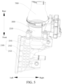
FIG. 5 is a schematic structural diagram of an air inlet cavity according to an embodiment of the present disclosure; -
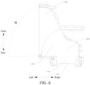
FIG. 6 is a cross-sectional view of an air inlet cavity according to an embodiment of the present disclosure; -
FIG. 7 is a cross-sectional view of an air outlet cavity according to an embodiment of the present disclosure; -
FIG. 8 is another cross-sectional view of an air outlet cavity according to an embodiment of the present disclosure; -
FIG. 9 is a cross-sectional view of an air inlet passage and a pressure stabilizing cavity according to an embodiment of the present disclosure; -
FIG. 10 is a cross-sectional view of an air inlet passage according to an embodiment of the present disclosure; and -
FIG. 11 is a schematic block diagram of a vehicle according to an embodiment of the present disclosure. - In the drawings:
- 1. air inlet assembly of an engine; 2. engine;
- 100. air inlet manifold; 110. pressure stabilizing cavity; 111. impact grid; 112. flow guiding baffle; 113. second air inlet; 120. air inlet passage; 121. first wall section; 122. second wall section;
- 200. intercooler; 210. first air inlet; 220. air outlet; 230. intercooler body; 240. air inlet cavity; 241. first air inlet section; 242. second air inlet section; 243. third air inlet section; 250. air outlet cavity; 251. first air outlet section; 252. second air outlet section; 253. third air outlet section; 260. reinforcing rib; 270. water inlet pipe connector; 280. water outlet pipe connector;
- 300. throttle valve;
- 400. cylinder head; 500. mounting bracket; 600. fixing bracket; 700. air inlet pipe; 800. engine cylinder block; and 1000. vehicle.
- The embodiments described with reference to the accompanying drawings are exemplary, and the following describes the embodiments of the present disclosure in detail.
- In the description of the present disclosure, it should be understood that, orientations or position relationships indicated by terms such as "center", "longitudinal", "transverse", "length", "width", "thickness", "up", "down", "front", "rear", "left", "right", "vertical", "horizontal", "top", "bottom", "inner", "outer", "clockwise", "counterclockwise", "axial", "radial", and "circumferential" are orientations or position relationship shown based on the accompanying drawings, and are merely used for describing the present disclosure and simplifying the description, rather than indicating or implying that the apparatus or element should have a particular orientation or be constructed and operated in a particular orientation, and therefore, should not be construed as a limitation on the present disclosure.
- In the description of the present disclosure, a "first feature" and a "second feature" may include one or more such features.
- In the description of the present disclosure, the meaning of "multiple" is two or more than two.
- An air inlet assembly 1 of an engine according to an embodiment of the present disclosure is described below with reference to the accompanying drawings.
- As shown in
FIG. 1 to FIG. 10 , the air inlet assembly 1 of an engine includes anair inlet manifold 100, anintercooler 200, and athrottle valve 300. - The
intercooler 200 has afirst air inlet 210 and anair outlet 220. Theair outlet 220 is directly attached to and in communication with theair inlet manifold 100. Thethrottle valve 300 is arranged on thefirst air inlet 210. - The temperature of exhaust discharged by an engine is very high, and the temperature of entering gas is increased due to the pressure increasing of a supercharger. In addition, in a process in which air is compressed, the density of the air increases, and further the temperature of air discharged by the supercharger increases. In addition, as the gas pressure increases, the density of oxygen decreases, which greatly affects the combustion effective efficiency of the engine. Therefore, for the air inlet assembly 1 of an engine according to the embodiments of the present disclosure, high-temperature air from the supercharger is cooled by using the
intercooler 200, and the air cooled by theintercooler 200 enters an engine cylinder block through theair inlet manifold 100 and is mixed with fuel for combustion to release energy, so that thermal load of theengine 2 can be greatly reduced, to improve an air inflow amount of theengine 2, thereby improving the combustion effective efficiency of theengine 2, and improving the power performance of a vehicle. - In addition, the
air outlet 220 of theintercooler 200 is directly attached to and in communication with theair inlet manifold 100, so that the structure formed by theintercooler 200 and theair inlet manifold 100 has a high integration level, and an air guide pipe between theintercooler 200 and theair inlet manifold 100 is omitted. This is conducive to saving materials and further reducing costs. In addition, an overall volume of the air inlet assembly 1 of an engine can be smaller, which is more conducive to arranging theintercooler 200 in an engine compartment of theengine 2 with a limited space, thereby improving mounting convenience. - In addition, the
throttle valve 300 is arranged on thefirst air inlet 210 to control an air inflow amount. With such an arrangement, an amount of gas that enters theintercooler 200 can be precisely controlled, so that the air inflow amount of theintercooler 200 is almost a required amount of the engine, and it can be ensured that air that enters theair inlet manifold 100 can be fully burned, thereby ensuring the combustion effective efficiency of the engine, and greatly reducing fuel consumption. Compared with an air inlet assembly of an engine in the related art, the air inlet assembly 1 of an engine in the present disclosure can control the air inflow amount of theintercooler 200 through thethrottle valve 300 according to different operating conditions and different air inflow amount requirements of theengine 2, so that different requirements can be met. In addition, an amount of gas that needs to be cooled by theintercooler 200 is reduced, so that the volume of theintercooler 200 can be effectively reduced, making the arrangement of the entire engine compartment compact, a space arrangement requirement of a small engine compartment can be met, and great convenience is provided for the freedom of overall vehicle design. - In addition, the
throttle valve 300 is arranged on thefirst air inlet 210, and it is not necessary to additionally arrange an air guide pipe between theair outlet 220 of theintercooler 200 and theair inlet manifold 100 to fix thethrottle valve 300, so that an air guide pipe between theair outlet 220 of theintercooler 200 and theair inlet manifold 100 is not required. In addition, thethrottle valve 300 is arranged on thefirst air inlet 210, so that an overall height is not increased, which is conducive to space arrangement. In addition, through the adjustment of the openness of thethrottle valve 300, the air inflow amount of theintercooler 200 can be adjusted to adequately meet an air inflow amount required by theengine 2. In this way, a problem of wasting an internal space of theintercooler 200 is avoided, so that the volume of theintercooler 200 is relatively small for better matching and arrangement in the compartment of theengine 2. - In this way, the air inlet assembly according to the embodiments of the present disclosure has advantages such as low costs, a small volume, and convenient mounting.
- Compared with an air inlet assembly of an engine in the related art, the air inlet assembly 1 of an engine in the embodiments of the present disclosure has the following beneficial effects:
- First, the required air inflow amount of the
engine 2 is almost an amount of gas entering theintercooler 200, so that it can be ensured that the gas entering theair inlet manifold 100 is fully burnt in theengine cylinder block 800. Second, compared with the related art, in the air inlet assembly 1 of an engine in this embodiment, theintercooler 200 is arranged with thethrottle valve 300 on thefirst air inlet 210, so that the amount of gas that needs to be cooled by theintercooler 200 is relatively reduced, and the volume of theintercooler 200 is reduced to be applicable to an arrangement in which the space of the engine compartment is small, thereby reducing costs. Third, different engine combustion requirements can be met by controlling thethrottle valve 300 according to different operating conditions and different air inflow amount requirements. - In some specific embodiments of the present disclosure, as shown in
FIG. 1 to FIG. 5 , theintercooler 200 includes anintercooler body 230, anair inlet cavity 240, and anair outlet cavity 250. - The
intercooler body 230 is arranged between theair inlet cavity 240 and theair outlet cavity 250, and in communication with both theair inlet cavity 240 and theair outlet cavity 250. Thefirst air inlet 210 is opened on theair inlet cavity 240, and theair outlet 220 is opened on theair outlet cavity 250. - With such an arrangement, one end of the
intercooler body 230 is in communication with theair inlet cavity 240, and thefirst air inlet 210 is opened on theair inlet cavity 240. After entering theair inlet cavity 240 through thefirst air inlet 210, gas is buffered in theair inlet cavity 240. Therefore, when entering theintercooler body 230 from theair inlet cavity 240, gas can enter theintercooler body 230 slowly and uniformly for cooling, to avoid a case of stress concentration due to a nonuniform flow rate of the gas. Further, thefirst air inlet 210 is opened on a side of theair inlet cavity 240. A smooth transition is provided at a corner of an inner wall of theair inlet cavity 240, so that gas is unlikely to undergo great disturbance in theair inlet cavity 240, so that the uniformity of the flow rate of the gas and the flowing smoothness of entering theintercooler body 230 can be effectively ensured, thereby improving cooling performance. - In addition, another end of the
intercooler body 230 is connected to theair outlet cavity 250, and theair outlet 220 is opened on theair outlet cavity 250. In this way, gas can slowly and uniformly enter theair inlet manifold 100. In addition, a smooth transition at a corner of an inner wall of theair outlet cavity 250 is similar to that of theair inlet cavity 240, so that it can be effectively ensured that gas enters theair inlet manifold 100 at a uniform flow rate, to eventually fully burn with fuel in theengine cylinder block 800, thereby improving combustion efficiency. - In some specific embodiments of the present disclosure, a gas storage capacity of the
intercooler body 230 is V1, and V1 satisfies a relation formula: 1200 ml ≤ V ≤ 1300 ml. With such an arrangement, a range of the air inflow amount required by theengine 2 can be adequately met, and the volume of theintercooler body 230 can be limited in a particular range. In addition, according to the engine compartment of theengine 2 with a limited space, the volume of theintercooler body 230 can be adaptively set, to better integrally arrange theintercooler 200 in the engine compartment of theengine 2 without occupying an excessive space, and a particular space is provided for arranging other components, thereby effectively optimizing the space arrangement in the compartment of the engine. - For the
intercooler 200, a length is a, a height is b, and a width is c. a, b, and c satisfy relation formulas: 320 mm ≤ a ≤ 380 mm, 45 mm ≤ b ≤ 60 mm, and 100 mm ≤ c ≤ 150 mm. In this way, a volume parameter of theintercooler 200 is designed to well meet the foregoing range of the gas storage capacity of theintercooler body 230. In addition, an air inflow amount requiring cooling of theintercooler 200 is small, and the product size can be reduced, and can be reduced by about 4/1 to 1/3 with respect to a volume parameter of an existingintercooler 200. In this way, when a required volume of theengine 2 is met, an overall volume of a power system can be effectively reduced, product costs are reduced, and a sufficient arrangement space can be provided for the engine compartment of theengine 2. Especially in a case that an arrangement space of a hybrid model is compact, theintercooler 200 with a small volume is very applicable. Certainly, the volume parameter of theintercooler 200 is not limited to the foregoing values. The volume parameter of theintercooler 200 may be set according to a designed required air inflow amount. - In some specific embodiments of the present disclosure, as shown in
FIG. 5 andFIG. 6 , theair inlet cavity 240 is arranged with a firstair inlet section 241, a secondair inlet section 242, and a thirdair inlet section 243 that are sequentially in communication. - The first
air inlet section 241 is in communication with thefirst air inlet 210, and the thirdair inlet section 243 is in communication with theintercooler body 230, to uniformly guide gas into theintercooler body 230. With such an arrangement, gas may sequentially pass through the firstair inlet section 241, the secondair inlet section 242, and the thirdair inlet section 243 to uniformly enter theintercooler body 230. - Further, a cross-sectional area of the third
air inlet section 243 is greater than a cross-sectional area of the firstair inlet section 241, and a cross-sectional area of the secondair inlet section 242 gradually increases from the firstair inlet section 241 to the thirdair inlet section 243. With such an arrangement, the cross-sectional area of the firstair inlet section 241 is small, the cross-sectional area of the secondair inlet section 242 gradually increases and eventually gradually becomes equal to the cross-sectional area of the thirdair inlet section 243. An appearance of theair inlet cavity 240 gradually increases in an air inlet direction. In this way, gas slowly enters from the firstair inlet section 241, and because the secondair inlet section 242 gradually expands to the thirdair inlet section 243, the gas uniformly enters theintercooler body 230. - Furthermore, as shown in
FIG. 6 , a spacing between a front side wall and a rear side wall of the secondair inlet section 242 gradually increases from right to left. An angle between the front side wall and the rear side wall of the secondair inlet section 242 is α. α satisfies a relation formula: 50° ≤ α ≤ 70°. - With such an arrangement, in the air inlet direction, instead of a conventional boss structure, the
air inlet cavity 240 is formed by the firstair inlet section 241, the secondair inlet section 242, and the thirdair inlet section 243 that are sequentially in communication. The cross-sectional area of the firstair inlet section 241 is small, and the cross-sectional area of the secondair inlet section 242 gradually increases and eventually gradually becomes equal to the cross-sectional area of the thirdair inlet section 243. In addition, the angle α between the front side wall and the rear side wall of the secondair inlet section 242 is set to 50° to 70°. In a front-rear direction, gas can slowly and uniformly enter the firstair inlet section 241, the secondair inlet section 242, and the thirdair inlet section 243 sequentially, i.e., is uniformly distributed in theair inlet cavity 240, so that the gas uniformly enters theintercooler body 230 for quick cooling, thereby effectively improving the air inflow uniformity of theintercooler 200. Compared with an existing intercooler structure, the air inflow uniformity of theintercooler 200 can be improved by over 10%, and cooling performance can be improved by 2% to 3% or more. - In some specific embodiments of the present disclosure, as shown in
FIG. 7 andFIG. 8 , theair outlet cavity 250 is arranged with a firstair outlet section 251, a secondair outlet section 252, and a thirdair outlet section 253 that are sequentially in communication, the firstair outlet section 251 is in communication with theair outlet 220, and the thirdair outlet section 253 is in communication with theintercooler body 230, to uniformly guide gas into theair inlet manifold 100. - With such an arrangement, gas cooled in the
intercooler body 230 may sequentially pass through the firstair outlet section 251, the secondair outlet section 252, and the thirdair outlet section 253 to uniformly enter theair inlet manifold 100, so that the gas uniformly enters theengine cylinder block 800 for full combustion. - Further, as shown in
FIG. 7 andFIG. 8 , a cross-sectional area of the thirdair outlet section 253 is less than a cross-sectional area of the firstair outlet section 251. A cross-sectional area of the secondair outlet section 252 gradually decreases from the firstair outlet section 251 to the thirdair outlet section 253. With such an arrangement, in an air outlet direction, the cross-sectional area of the firstair outlet section 251 is large, and the cross-sectional area of the secondair outlet section 252 gradually decreases and decreases to be equal to the cross-sectional area of the thirdair outlet section 253, so that theair outlet cavity 250 has a shape of gradually decreasing in the air outlet direction. In this way, after a large amount of gas enters the firstair outlet section 251, because the secondair outlet section 252 gradually decreases to the thirdair outlet section 253, the gas uniformly enters theair inlet manifold 100. - Furthermore, as shown in
FIG. 7 andFIG. 8 , a spacing between a front side wall and a rear side wall of the secondair outlet section 252 gradually decreases from right to left. An angle between the rear side wall of the secondair outlet section 252 and a cross-section of theair outlet cavity 250 is β. β satisfies a relation formula: 20° ≤ β ≤ 40°. In this way, in the air outlet direction, the cross-sectional area of the firstair outlet section 251 is large, the cross-sectional area of the secondair outlet section 252 gradually decreases and decreases to be equal to the cross-sectional area of the thirdair outlet section 253, and the angle β between the rear side wall of the secondair outlet section 252 and the cross-section of theair outlet cavity 250 is set to 20° to 40°, so that gas can sequentially pass through the firstair outlet section 251, the secondair outlet section 252, and the thirdair outlet section 253, and can slowly and uniformly flow into theair inlet manifold 100, which helps to reduce a flow rate of the gas in theair inlet manifold 100, thereby improving cooling efficiency of theintercooler 200, and improving cooling performance by 2% to 3% or even more. - In some specific embodiments of the present disclosure, as shown in
FIG. 8 , a spacing between an upper side wall and a lower side wall of the secondair outlet section 252 gradually decreases from right to left. An angle between the upper side wall and the lower side wall of the secondair outlet section 252 is γ. γ satisfies a relation formula: 25° ≤ γ ≤ 35°. - With such an arrangement, the angle γ between the upper side wall and the lower side wall of the second
air outlet section 252 is set to 25° to 35°, which facilitates flowing of the gas at a uniform rate, reduces a loss in the flowing of the gas, and effectively reduces a pressure loss in theintercooler 200, thereby ensuring that an air inflow amount of theair inlet manifold 100 is nearly the required volume of theengine 2. In addition, the angle between the rear side wall of the secondair outlet section 252 and the cross-section of theair outlet cavity 250 is set to β in combination, so that gas flows slowly and uniformly, thereby further improving the cooling efficiency of theintercooler 200. - In some embodiments of the disclosure, multiple reinforcing
ribs 260 are arranged on outer walls of theair inlet cavity 240 and/or theair outlet cavity 250, and the multiple reinforcingribs 260 are distributed in a staggered manner. With such an arrangement, the reinforcingribs 260 are arranged on theair inlet cavity 240 and/or theair outlet cavity 250, and the reinforcingribs 260 are distributed in a mesh form on outer surfaces of theair inlet cavity 240 and/or theair outlet cavity 250, so that the structural strength of theair inlet cavity 240 and/or theair outlet cavity 250 can be enhanced, thereby improving the modality of theintercooler 200. - In addition, the
intercooler body 230 is arranged with a cooling channel, and theintercooler body 230 is arranged with a waterinlet pipe connector 270 in communication with one end of the cooling channel and a wateroutlet pipe connector 280 in communication with another end of the cooling channel, to perform water cooling on gas that enters theintercooler body 230. In addition, a left bracket is arranged at each of an upper part and a lower part on a rear side of theair inlet cavity 240, and a right bracket is arranged at each of an upper part and a lower part on a rear side of theair outlet cavity 250. With such an arrangement, the structure is compact, a space of the engine compartment can be saved, mounting is reliable, and vibration reduction and noise avoidance can be reduced. In addition, a weight is small, lightweight design is met, fuel consumption of the overall vehicle can be reduced, and pipe arrangement in the engine compartment can be optimized, thereby ensuring aesthetics. - In some specific embodiments of the present disclosure, the
air inlet manifold 100 is arranged with apressure stabilizing cavity 110 and anair inlet passage 120. - One end of the
air inlet passage 120 is in communication with thepressure stabilizing cavity 110, and another end of theair inlet passage 120 is in communication with theengine 2. A bottom wall of theair inlet passage 120 includes afirst wall section 121. Thefirst wall section 121 is connected to a bottom wall of thepressure stabilizing cavity 110 and is arranged obliquely downward with respect to the bottom wall of thepressure stabilizing cavity 110. An angle δ is formed between thefirst wall section 121 and the bottom wall of thepressure stabilizing cavity 110. 2° ≤ δ ≤ 5°. - In this way, gas that enters the
air inlet manifold 100 can be first buffered in thepressure stabilizing cavity 110, and then is guided into cylinders of theengine 2 through theair inlet passage 120, so that normal operation of theair inlet manifold 100 can be implemented. In addition, the angle is formed between thefirst wall section 121 of theair inlet passage 120 and the bottom wall of thepressure stabilizing cavity 110, and in this way, condensed water can naturally flow downward along asecond wall section 122 under the action of gravity, so that condensed water can be further kept from accumulating at thepressure stabilizing cavity 110 and theair inlet passage 120, and the operating performance of theengine 2 can be further improved. - In addition, 2° ≤ δ ≤ 5°, so that the angle of the bottom wall of the
pressure stabilizing cavity 110 being downward obliquely with respect to thefirst wall section 121 is set within an appropriate range. In this way, in one aspect, an angle between the bottom wall of thepressure stabilizing cavity 110 and the bottom wall of theair inlet passage 120 can be kept from being excessively small, to ensure that condensed water can naturally flow to the bottom wall of theair inlet passage 120 along the bottom wall of thepressure stabilizing cavity 110, thereby keeping condensed water from accumulating in thepressure stabilizing cavity 110. In another aspect, the angle between the bottom wall of thepressure stabilizing cavity 110 and the bottom wall of theair inlet passage 120 can be kept from being excessively large, to improve the buffering effect of thepressure stabilizing cavity 110 for gas. In this way, the structural design of theair inlet manifold 100 can be optimized, so that normal operation of theair inlet manifold 100 can be ensured, and condensed water can be kept from accumulating in theair inlet manifold 100, so that the operating performance of theengine 2 can be improved. - Further, as shown in
FIG. 9 , the bottom wall of theair inlet passage 120 further includes thesecond wall section 122. - The
second wall section 122 is connected to a side of thefirst wall section 121 away from thepressure stabilizing cavity 110. Thesecond wall section 122 is arranged obliquely downward with respect to thefirst wall section 121. An angle ε is formed between thesecond wall section 122 and thefirst wall section 121. 24° ≤ ε ≤ 26°. - Therefore, the angle between the
second wall section 122 and thefirst wall section 121 may be set within an appropriate range. In this way, the angle of thesecond wall section 122 being downward obliquely with respect to thefirst wall section 121 may be set to be appropriate, so that when condensed water flows to thesecond wall section 122 from thefirst wall section 121, a flow rate of the condensed water can be controlled within an appropriate range, making the flowing of the condensed water on thesecond wall section 122 stabler and smoother. - It should be noted that a connection between the
first wall section 121 and thesecond wall section 122 may be arc-shaped. In this way, thefirst wall section 121 and thesecond wall section 122 may be connected by a smooth transition, so that a flow path of condensed water can be smoother, and the stability and smoothness of condensed water flowing on the bottom wall of theair inlet passage 120 can be further improved. - In addition, the angle formed between the bottom wall of the
pressure stabilizing cavity 110 and the bottom wall of theair inlet passage 120 and an angle formed between a tangent of thesecond wall section 122 and thefirst wall section 121 are further defined, so that the angle formed between the bottom wall of thepressure stabilizing cavity 110 and the bottom wall of theair inlet passage 120 and the angle formed between the tangent of thesecond wall section 122 and thefirst wall section 121 can be controlled within better ranges, and the structural design of theair inlet manifold 100 can be further optimized, thereby ensuring the normal operation of theair inlet manifold 100, and further improving the operating performance of theengine 2. - In some specific embodiments of the present disclosure, a volume of the
pressure stabilizing cavity 110 is V2, and V2 satisfies a relation formula: 1 L < V2 < 1.2 L. - In this way, the volume of the
pressure stabilizing cavity 110 may be set within an appropriate range, so that on the premise of ensuring the structural compactness of theair inlet manifold 100, thepressure stabilizing cavity 110 can effectively buffer gas that enters theair inlet manifold 100, and stable gas enters theengine 2 through theair inlet passage 120, thereby ensuring the normal operation of theengine 2, and improving the operating performance of theengine 2. - In some specific embodiments of the present disclosure, a length of the
air inlet passage 120 is L, and L satisfies a relation formula: 70 mm < L < 80 mm. The length of theair inlet passage 120 means an extension length of theair inlet passage 120 in the air inlet direction, i.e., a sum of lengths of thefirst wall section 121 and thesecond wall section 122. With such an arrangement, the length of theair inlet passage 120 may be set within an appropriate range. When theengine 2 operates in a high-speed range, the power and torque can be improved, and fuel consumption can be reduced, so that the structural design of theair inlet manifold 100 can be further optimized, thereby further improving the operating performance of theengine 2. - In some specific embodiments of the present disclosure, as shown in
FIG. 10 , thepressure stabilizing cavity 110 is arranged with animpact separation piece 1101 and aflow guiding piece 1102. - The
impact separation piece 1101 is located in thepressure stabilizing cavity 110, to impact entering gas to reduce generation of condensed water. Theflow guiding piece 1102 is arranged in thepressure stabilizing cavity 110, to guide condensed water in thepressure stabilizing cavity 110 to theair inlet passage 120. In this way, condensed water that enters thepressure stabilizing cavity 110 can impact theimpact separation piece 1101, and condensed water that flows quickly can spread to different positions of thepressure stabilizing cavity 110, and the flow rate of condensed water can be reduced. In addition, when the condensed water in thepressure stabilizing cavity 110 flows into theair inlet passage 120, theflow guiding piece 1102 can guide condensed water into theair inlet passage 120, so that the flowing of condensed water is stabler, a flow of condensed water that enters theair inlet passage 120 is more uniform, flows of condensed water that enters the cylinders through theair inlet passage 120 can be more uniform, and the operating performance of theengine 2 can be improved. - Further, as shown in
FIG. 10 , theimpact separation piece 1101 is animpact grid 111, and theflow guiding piece 1102 includes multiple flow guiding baffles 112. - The
pressure stabilizing cavity 110 is arranged with asecond air inlet 113. Theimpact grid 111 corresponds to thesecond air inlet 113, to impact entering gas to reduce generation of condensed water at thesecond air inlet 113. Theimpact grid 111 mainly impacts and rubs entering gas at thesecond air inlet 113, so that heat is generated to make the gas temperature of the entering gas rise, thereby reducing the generation of condensed water. - Multiple
air inlet passages 120 are provided. Each of the multipleflow guiding baffles 112 is arranged extending toward theair inlet passage 120. The multipleflow guiding baffles 112 guide condensed water in thepressure stabilizing cavity 110 to the multipleair inlet passages 120. - Specifically, the multiple
air inlet passages 120 are correspondingly in communication with the cylinders of theengine 2. When gas in theintercooler 200 enters thepressure stabilizing cavity 110 through thesecond air inlet 113, the isolation of condensed water at thesecond air inlet 113 can be accelerated. A transition between thesecond air inlet 113 and theintercooler 200 may be "U"-shaped to accelerate the generation of condensed water. Condensed water may sequentially pass through thepressure stabilizing cavity 110 and the multipleair inlet passages 120 and correspondingly flow into combustion chambers of the cylinders. Theimpact grid 111 is arranged in thepressure stabilizing cavity 110, and theimpact grid 111 corresponds to thesecond air inlet 113, so that condensed water that enters thepressure stabilizing cavity 110 can impact theimpact grid 111, and condensed water that flows quickly can spread to different positions of thepressure stabilizing cavity 110, and the flow rate of condensed water can be reduced. - The multiple
flow guiding baffles 112 are arranged, and theflow guiding baffles 112 are arranged extending toward theair inlet passages 120. In this way, when condensed water in thepressure stabilizing cavity 110 flows into theair inlet passages 120, theflow guiding baffles 112 can guide the condensed water into theair inlet passages 120. In this way, the flowing of condensed water can be stabler, and flows of condensed water that enters theair inlet passages 120 are more uniform, so that flows of condensed water that flows into the cylinders through theair inlet passages 120 are more uniform, and the operating performance of theengine 2 can be improved. - It should be noted that heights and widths of the
impact grid 111 and theflow guiding baffles 112 should not be excessively large. In this way, the arrangement of theimpact grid 111 and theflow guiding baffles 112 can be kept from affecting normal air inflow of theair inlet manifold 100, and the length and direction of theflow guiding baffles 112 can be adjusted according to an actual flow direction of condensed water inside theair inlet manifold 100. - An
engine 2 according to an embodiment of the present disclosure is described below with reference to the accompanying drawings. As shown inFIG. 1 to FIG. 5 , theengine 2 includes anengine cylinder block 800, acylinder head 400, and an air inlet assembly 1 of an engine. - The
cylinder head 400 covers above theengine cylinder block 800. A mountingbracket 500 is arranged on thecylinder head 400. In an up-down direction, theintercooler 200 is located above theair inlet manifold 100. The mountingbracket 500 is fixedly connected to theintercooler 200 and/or thethrottle valve 300. With such an arrangement, theengine 2 is in communication with theair inlet manifold 100, so that air cooled in theintercooler 200 enters theengine cylinder block 800 through theair inlet manifold 100 for full combustion. In addition, theintercooler 200 with a small volume is arranged above theair inlet manifold 100, so that the entire mounting structure is compact, which is conducive to the freedom design of an engine compartment of theengine 2, and reduces costs. In addition, to reduce the vibration of theintercooler 200, the mountingbracket 500 is arranged on thecylinder head 400, and is configured to fixedly connect theintercooler 200 and/or a first air inlet valve 30. In this way, the mounting modality of theentire intercooler 200 can be effectively improved, thereby improving noise, vibration, and harshness (NVH) performance. - The mounting
bracket 500 is fixed at thecylinder head 400, and is connected to thethrottle valve 300, so that thethrottle valve 300 can be better and stably mounted at thefirst air inlet 210 of theintercooler 200. In addition, multiple fixingbrackets 600 are arranged at intervals on theair inlet manifold 100. Theair inlet manifold 100 can be reliably fixed on theengine cylinder block 800 or a frame through the multiple fixingbrackets 600, so that the mounting modality of the engine is improved, thereby improving the NVH performance. In addition, a mounting hole is provided in the mountingbracket 500. One end of the mountingbracket 500 may be fixedly connected to a flange structure on thethrottle valve 300, and another end of the mountingbracket 500 may be fixedly connected to thecylinder head 400 by a fastener, so that thethrottle valve 300 is fixed reliably. - Through the use of the air inlet assembly 1 of the engine according to the foregoing embodiments of the present disclosure, the
engine 2 according to embodiments of the second aspect of the present disclosure has advantages such as low costs, a small volume, and convenient mounting. - A
vehicle 1000 according to an embodiment of the present disclosure is described below with reference toFIG. 11 . The vehicle includes theengine 2 according to the foregoing embodiment of the present disclosure. - The
vehicle 1000 may be a hybrid vehicle. In the hybrid vehicle, because a hybrid system needs to be arranged, an internal space of the hybrid vehicle is more compact. In this case, theengine 2 provided in the foregoing embodiments is used in thevehicle 1000 in this embodiment, and theengine 2 has the air inlet assembly 1 of an engine in the foregoing embodiments. In the air inlet assembly 1 of theengine 2, a volume of theintercooler 200 may be set small, to meet a requirement of a compact internal space of the hybrid vehicle. - Through the use of the
engine 2 according to the foregoing embodiments of the present disclosure, thevehicle 1000 according to embodiments of the second aspect of the present disclosure has advantages such as low costs, a small volume, and convenient mounting. - Other compositions and operations of the air inlet assembly 1 of an engine, the
engine 2, and thevehicle 1000 according to the embodiments of the present disclosure are known to those of ordinary skill in the art, and are not described herein again in detail. - In the description of this specification, the description of the reference terms such as "an embodiment", "some embodiments", "exemplary embodiments", "example", "specific example", or "some examples" means that the specific features, structures, materials or characteristics described with reference to the embodiment or example are included in at least one embodiment or example of the present disclosure. In this specification, schematic descriptions of the foregoing terms do not necessarily directed at a same embodiment or example.
- Although the embodiments of the present disclosure have been shown and described, a person of ordinary skill in the art should understand that various changes, modifications, replacements and variations may be made to the embodiments without departing from the principles and spirit of the present disclosure, and the scope of the present disclosure is as defined by the appended claims and their equivalents.
Claims (20)
- An air inlet assembly (1) of an engine, comprising:an air inlet manifold (100);an intercooler (200), the intercooler (200) having a first air inlet (210) and an air outlet (220), and the air outlet (220) being directly attached to and in communication with the air inlet manifold (100); anda throttle valve (300), the throttle valve (300) being arranged on the first air inlet (210) to control an air inflow amount.
- The air inlet assembly (1) of an engine according to claim 1, wherein the intercooler (200) comprises:an intercooler body (230);an air inlet cavity (240); andan air outlet cavity (250), the intercooler body (230) being arranged between the air inlet cavity (240) and the air outlet cavity (250), and in communication with both the air inlet cavity (240) and the air outlet cavity (250), the first air inlet (210) being opened on the air inlet cavity (240), and the air outlet (220) being opened on the air outlet cavity (250).
- The air inlet assembly (1) of an engine according to claim 2, wherein a gas storage capacity of the intercooler body (230) is V1, and V1 satisfies a relation formula: 1200 ml ≤ V1 ≤ 1300 ml.
- The air inlet assembly (1) of an engine according to claim 2 or 3, wherein the air inlet cavity (240) is arranged with a first air inlet section (241), a second air inlet section (242), and a third air inlet section (243) that are sequentially in communication, the first air inlet section (241) is in communication with the first air inlet (210), and the third air inlet section (243) is in communication with the intercooler body (230), to uniformly guide gas into the intercooler body (230).
- The air inlet assembly (1) of an engine according to claim 4, wherein a cross-sectional area of the third air inlet section (243) is greater than a cross-sectional area of the first air inlet section (241), and a cross-sectional area of the second air inlet section (242) gradually increases from the first air inlet section (241) to the third air inlet section (243).
- The air inlet assembly (1) of an engine according to claim 5, wherein a spacing between a front side wall and a rear side wall of the second air inlet section (242) gradually increases from right to left, an angle between the front side wall and the rear side wall of the second air inlet section (242) is α, and α satisfies a relation formula: 50° ≤ α ≤ 70°.
- The air inlet assembly (1) of an engine according to any one of claims 2 to 6, wherein the air outlet cavity (250) is arranged with a first air outlet section (251), a second air outlet section (252), and a third air outlet section (253) that are sequentially in communication, the first air outlet section (251) is in communication with the air outlet (220), and the third air outlet section (253) is in communication with the intercooler body (230), to uniformly guide gas into the air inlet manifold (100).
- The air inlet assembly (1) of an engine according to claim 7, wherein a cross-sectional area of the third air outlet section (253) is less than a cross-sectional area of the first air outlet section (251), and a cross-sectional area of the second air outlet section (252) gradually decreases from the first air outlet section (251) to the third air outlet section (253).
- The air inlet assembly (1) of an engine according to claim 8, wherein a spacing between a front side wall and a rear side wall of the second air outlet section (252) gradually decreases from right to left, an angle between the rear side wall of the second air outlet section (252) and a cross-section of the air outlet cavity (250) is β, and β satisfies a relation formula: 20° ≤ β ≤ 40°.
- The air inlet assembly (1) of an engine according to claim 8 or 9, wherein a spacing between an upper side wall and a lower side wall of the second air outlet section (252) gradually decreases from right to left, an angle between the upper side wall and the lower side wall of the second air outlet section (252) is γ, and γ satisfies a relation formula: 25° ≤ γ ≤ 35°.
- The air inlet assembly (1) of an engine according to any one of claims 2 to 10, wherein a plurality of reinforcing ribs (260) are arranged on outer walls of the air inlet cavity (240) and/or the air outlet cavity (250), and the plurality of reinforcing ribs (260) are distributed in a staggered manner.
- The air inlet assembly (1) of an engine according to any one of claims 2 to 11, wherein the intercooler body (230) is arranged with a cooling channel, and the intercooler body (230) is arranged with a water inlet pipe connector (270) in communication with one end of the cooling channel and a water outlet pipe connector (280) in communication with another end of the cooling channel.
- The air inlet assembly (1) of an engine according to any one of claims 1 to 11, wherein the air inlet manifold (100) is arranged with a pressure stabilizing cavity (110) and an air inlet passage (120), one end of the air inlet passage (120) is in communication with the pressure stabilizing cavity (110), another end of the air inlet passage (120) is in communication with an engine cylinder block (800), a bottom wall of the air inlet passage (120) comprises a first wall section (121), the first wall section (121) is connected to a bottom wall of the pressure stabilizing cavity (110) and is arranged obliquely downward with respect to the bottom wall of the pressure stabilizing cavity (110), an angle δ is formed between the first wall section (121) and the bottom wall of the pressure stabilizing cavity (110), and 2° ≤ δ ≤ 5°.
- The air inlet assembly (1) of an engine according to claim 13, wherein the bottom wall of the air inlet passage (120) further comprises:
a second wall section (122), the second wall section (122) being connected to a side of the first wall section (121) away from the pressure stabilizing cavity (110), the second wall section (122) being arranged obliquely downward with respect to the first wall section (121), an angle ε being formed between the second wall section (122) and the first wall section (121), and 24° ≤ ε ≤ 26°. - The air inlet assembly (1) of an engine according to claim 13 or 14, wherein a volume of the pressure stabilizing cavity (110) is V2, and V2 satisfies a relation formula: 1 L < V2 < 1.2 L.
- The air inlet assembly (1) of an engine according to any one of claims 13 to 15, wherein a length of the air inlet passage (120) is L, and L satisfies a relation formula: 70 mm < L < 80 mm.
- The air inlet assembly (1) of an engine according to any one of claims 13 to 16, wherein the pressure stabilizing cavity (110) is arranged with:an impact separation piece (1101), the impact separation piece (1101) being located in the pressure stabilizing cavity (110), to impact entering gas to reduce generation of condensed water; anda flow guiding piece (1102), the flow guiding piece (1102) being arranged in the pressure stabilizing cavity (110), and being configured to guide condensed water in the pressure stabilizing cavity (110) to the air inlet passage (120).
- The air inlet assembly (1) of an engine according to claim 17, wherein the impact separation piece is an impact grid (111), the pressure stabilizing cavity (110) is arranged with a second air inlet (113), and the impact grid (111) corresponds to the second air inlet (113), to impact entering gas to reduce generation of condensed water; and
the flow guiding piece comprises a plurality of flow guiding baffles (112), a plurality of air inlet passages (120) are provided, each of the plurality of flow guiding baffles (112) extends toward the air inlet passages (120), and the plurality of flow guiding baffles (112) guide condensed water in the pressure stabilizing cavity (110) to the plurality of air inlet passages (120). - An engine (2), comprising:an engine cylinder block (800);a cylinder head (400), the cylinder head (400) covering above the engine cylinder block (800), and a mounting bracket (500) being arranged on the cylinder head (400); andthe air inlet assembly (1) of an engine according to any one of claims 1 to 18, in an up-down direction, the intercooler (200) being located above the air inlet manifold (100), and the mounting bracket (500) being fixedly connected to the intercooler (200) and/or the throttle valve (300).
- A vehicle (1000), comprising the engine (2) according to claim 19.
Applications Claiming Priority (2)
| Application Number | Priority Date | Filing Date | Title |
|---|---|---|---|
| CN202210905127.2A CN117514547A (en) | 2022-07-29 | 2022-07-29 | Engine air intake components, engines and vehicles |
| PCT/CN2023/097463 WO2024021850A1 (en) | 2022-07-29 | 2023-05-31 | Air inlet assembly of engine, engine, and vehicle |
Publications (2)
| Publication Number | Publication Date |
|---|---|
| EP4563807A1 true EP4563807A1 (en) | 2025-06-04 |
| EP4563807A4 EP4563807A4 (en) | 2025-10-22 |
Family
ID=89705301
Family Applications (1)
| Application Number | Title | Priority Date | Filing Date |
|---|---|---|---|
| EP23845063.9A Pending EP4563807A4 (en) | 2022-07-29 | 2023-05-31 | AIR INTAKE ARRANGEMENT FOR ENGINE, MOTOR AND VEHICLE |
Country Status (6)
| Country | Link |
|---|---|
| US (1) | US20250172113A1 (en) |
| EP (1) | EP4563807A4 (en) |
| JP (1) | JP2025525671A (en) |
| KR (1) | KR20250039433A (en) |
| CN (1) | CN117514547A (en) |
| WO (1) | WO2024021850A1 (en) |
Family Cites Families (17)
| Publication number | Priority date | Publication date | Assignee | Title |
|---|---|---|---|---|
| JP4696978B2 (en) * | 2006-03-09 | 2011-06-08 | 日産自動車株式会社 | Intake passage structure |
| CN104428524B (en) * | 2012-07-18 | 2017-03-08 | 日产自动车株式会社 | intake manifold |
| CN102852678B (en) * | 2012-09-26 | 2014-12-24 | 长城汽车股份有限公司 | Supercharged engine intake manifold for integrated intercooler |
| US9470190B2 (en) * | 2014-11-05 | 2016-10-18 | Ford Global Technologies, Llc | Engine intake manifold having a condensate-containment tray |
| US20160169166A1 (en) * | 2014-12-10 | 2016-06-16 | Hyundai Motor Company | Structure of engine system |
| KR101719582B1 (en) * | 2015-12-30 | 2017-03-24 | 주식회사 현대케피코 | Condensate Water Dispersion Structure For Intake Manifold |
| US10180102B2 (en) * | 2016-02-12 | 2019-01-15 | Mazda Motor Corporation | Intake air cooling device for engine |
| JP6344405B2 (en) * | 2016-02-12 | 2018-06-20 | マツダ株式会社 | Engine intake cooling system |
| FR3073257B1 (en) * | 2017-11-08 | 2021-02-19 | Renault Sas | AIR INTAKE DEVICE FOR THERMAL ENGINE |
| JP6538814B2 (en) * | 2017-12-13 | 2019-07-03 | 本田技研工業株式会社 | Intake manifold |
| JP7138042B2 (en) * | 2018-12-27 | 2022-09-15 | ダイハツ工業株式会社 | automotive internal combustion engine |
| US10815946B1 (en) * | 2019-06-21 | 2020-10-27 | GM Global Technology Operations LLC | Intake manifold plenum and runner with condensate drains |
| DE102019121494A1 (en) * | 2019-08-09 | 2021-02-11 | Mann+Hummel Gmbh | Heat exchanger arrangement, method for producing a heat exchanger arrangement and internal combustion engine with heat exchanger arrangement |
| JP7456258B2 (en) * | 2020-04-17 | 2024-03-27 | マツダ株式会社 | Intake passage structure for vehicle engine |
| CN216077362U (en) * | 2021-09-10 | 2022-03-18 | 义乌吉利动力总成有限公司 | Air inlet arrangement structure of automobile engine |
| CN113685294B (en) * | 2021-09-10 | 2022-11-25 | 宁波吉利罗佑发动机零部件有限公司 | Air intake system and car |
| CN218235306U (en) * | 2022-07-29 | 2023-01-06 | 比亚迪股份有限公司 | Air intake components for engines, engines and vehicles |
-
2022
- 2022-07-29 CN CN202210905127.2A patent/CN117514547A/en active Pending
-
2023
- 2023-05-31 WO PCT/CN2023/097463 patent/WO2024021850A1/en not_active Ceased
- 2023-05-31 KR KR1020257005131A patent/KR20250039433A/en active Pending
- 2023-05-31 EP EP23845063.9A patent/EP4563807A4/en active Pending
- 2023-05-31 JP JP2025504739A patent/JP2025525671A/en active Pending
-
2025
- 2025-01-27 US US19/037,939 patent/US20250172113A1/en active Pending
Also Published As
| Publication number | Publication date |
|---|---|
| US20250172113A1 (en) | 2025-05-29 |
| EP4563807A4 (en) | 2025-10-22 |
| WO2024021850A1 (en) | 2024-02-01 |
| KR20250039433A (en) | 2025-03-20 |
| CN117514547A (en) | 2024-02-06 |
| JP2025525671A (en) | 2025-08-05 |
Similar Documents
| Publication | Publication Date | Title |
|---|---|---|
| CN218235306U (en) | Air intake components for engines, engines and vehicles | |
| CN106368846B (en) | A kind of engine cylinder cap of Integrated design | |
| CN113685294B (en) | Air intake system and car | |
| EP4563807A1 (en) | Air inlet assembly of engine, engine, and vehicle | |
| CN218624469U (en) | Intake manifold and engine assembly | |
| US20250146458A1 (en) | Driving assembly and vehicle having same | |
| US4848280A (en) | Intake apparatus for internal combustion engine | |
| CN215444237U (en) | Motorcycle engine and cylinder head air inlet structure thereof | |
| CN217761461U (en) | Automobile supercharger shell with heat insulation effect | |
| CN217002027U (en) | Upright rear-drive tightly-coupled exhaust manifold | |
| CN222254135U (en) | Engine and vehicle | |
| CN117569942A (en) | An engine cylinder head and an engine | |
| US20120325182A1 (en) | Connection box with a charge air cooling arrangement of an internal combustion engine | |
| CN209800133U (en) | Engine intake port and engine cylinder head and engine | |
| JP5310437B2 (en) | EGR diffusion unit | |
| CN217681968U (en) | Water-cooling intercooler support | |
| CN223839212U (en) | Oil-gas separator and engine | |
| US12503990B2 (en) | Exhaust gas recirculation system, engine assembly, and vehicle | |
| CN217270462U (en) | Intercooler assembly | |
| KR102805128B1 (en) | Electric supercharger arrangement | |
| CN220909835U (en) | Cylinder head, engine and vehicle | |
| CN223825085U (en) | Oil-gas separator and engine | |
| CN219220606U (en) | Double-cylinder engine | |
| CN219638956U (en) | Integrated cylinder cover, engine and car | |
| CN214577427U (en) | Cooling Air Duct System for Diesel Engines |
Legal Events
| Date | Code | Title | Description |
|---|---|---|---|
| STAA | Information on the status of an ep patent application or granted ep patent |
Free format text: STATUS: THE INTERNATIONAL PUBLICATION HAS BEEN MADE |
|
| PUAI | Public reference made under article 153(3) epc to a published international application that has entered the european phase |
Free format text: ORIGINAL CODE: 0009012 |
|
| STAA | Information on the status of an ep patent application or granted ep patent |
Free format text: STATUS: REQUEST FOR EXAMINATION WAS MADE |
|
| 17P | Request for examination filed |
Effective date: 20250224 |
|
| AK | Designated contracting states |
Kind code of ref document: A1 Designated state(s): AL AT BE BG CH CY CZ DE DK EE ES FI FR GB GR HR HU IE IS IT LI LT LU LV MC ME MK MT NL NO PL PT RO RS SE SI SK SM TR |
|
| A4 | Supplementary search report drawn up and despatched |
Effective date: 20250924 |
|
| RIC1 | Information provided on ipc code assigned before grant |
Ipc: F02M 35/10 20060101AFI20250918BHEP Ipc: F02B 29/04 20060101ALI20250918BHEP |
|
| DAV | Request for validation of the european patent (deleted) | ||
| DAX | Request for extension of the european patent (deleted) |