EP4563375A1 - Heat pump air-conditioning system, and vehicle - Google Patents
Heat pump air-conditioning system, and vehicle Download PDFInfo
- Publication number
- EP4563375A1 EP4563375A1 EP23845658.6A EP23845658A EP4563375A1 EP 4563375 A1 EP4563375 A1 EP 4563375A1 EP 23845658 A EP23845658 A EP 23845658A EP 4563375 A1 EP4563375 A1 EP 4563375A1
- Authority
- EP
- European Patent Office
- Prior art keywords
- heat exchanger
- air conditioning
- water
- circuit
- refrigerant
- Prior art date
- Legal status (The legal status is an assumption and is not a legal conclusion. Google has not performed a legal analysis and makes no representation as to the accuracy of the status listed.)
- Pending
Links
Images


Classifications
-
- B—PERFORMING OPERATIONS; TRANSPORTING
- B60—VEHICLES IN GENERAL
- B60K—ARRANGEMENT OR MOUNTING OF PROPULSION UNITS OR OF TRANSMISSIONS IN VEHICLES; ARRANGEMENT OR MOUNTING OF PLURAL DIVERSE PRIME-MOVERS IN VEHICLES; AUXILIARY DRIVES FOR VEHICLES; INSTRUMENTATION OR DASHBOARDS FOR VEHICLES; ARRANGEMENTS IN CONNECTION WITH COOLING, AIR INTAKE, GAS EXHAUST OR FUEL SUPPLY OF PROPULSION UNITS IN VEHICLES
- B60K11/00—Arrangement in connection with cooling of propulsion units
- B60K11/02—Arrangement in connection with cooling of propulsion units with liquid cooling
-
- B—PERFORMING OPERATIONS; TRANSPORTING
- B60—VEHICLES IN GENERAL
- B60H—ARRANGEMENTS OF HEATING, COOLING, VENTILATING OR OTHER AIR-TREATING DEVICES SPECIALLY ADAPTED FOR PASSENGER OR GOODS SPACES OF VEHICLES
- B60H1/00—Heating, cooling or ventilating devices
- B60H1/32—Cooling devices
- B60H1/3204—Cooling devices using compression
- B60H1/3223—Cooling devices using compression characterised by the arrangement or type of the compressor
-
- B—PERFORMING OPERATIONS; TRANSPORTING
- B60—VEHICLES IN GENERAL
- B60H—ARRANGEMENTS OF HEATING, COOLING, VENTILATING OR OTHER AIR-TREATING DEVICES SPECIALLY ADAPTED FOR PASSENGER OR GOODS SPACES OF VEHICLES
- B60H1/00—Heating, cooling or ventilating devices
- B60H1/00271—HVAC devices specially adapted for particular vehicle parts or components and being connected to the vehicle HVAC unit
- B60H1/00278—HVAC devices specially adapted for particular vehicle parts or components and being connected to the vehicle HVAC unit for the battery
-
- B—PERFORMING OPERATIONS; TRANSPORTING
- B60—VEHICLES IN GENERAL
- B60H—ARRANGEMENTS OF HEATING, COOLING, VENTILATING OR OTHER AIR-TREATING DEVICES SPECIALLY ADAPTED FOR PASSENGER OR GOODS SPACES OF VEHICLES
- B60H1/00—Heating, cooling or ventilating devices
- B60H1/00357—Air-conditioning arrangements specially adapted for particular vehicles
- B60H1/00385—Air-conditioning arrangements specially adapted for particular vehicles for vehicles having an electrical drive, e.g. hybrid or fuel cell
-
- B—PERFORMING OPERATIONS; TRANSPORTING
- B60—VEHICLES IN GENERAL
- B60H—ARRANGEMENTS OF HEATING, COOLING, VENTILATING OR OTHER AIR-TREATING DEVICES SPECIALLY ADAPTED FOR PASSENGER OR GOODS SPACES OF VEHICLES
- B60H1/00—Heating, cooling or ventilating devices
- B60H1/00485—Valves for air-conditioning devices, e.g. thermostatic valves
-
- B—PERFORMING OPERATIONS; TRANSPORTING
- B60—VEHICLES IN GENERAL
- B60H—ARRANGEMENTS OF HEATING, COOLING, VENTILATING OR OTHER AIR-TREATING DEVICES SPECIALLY ADAPTED FOR PASSENGER OR GOODS SPACES OF VEHICLES
- B60H1/00—Heating, cooling or ventilating devices
- B60H1/00642—Control systems or circuits; Control members or indication devices for heating, cooling or ventilating devices
- B60H1/00814—Control systems or circuits characterised by their output, for controlling particular components of the heating, cooling or ventilating installation
- B60H1/00878—Control systems or circuits characterised by their output, for controlling particular components of the heating, cooling or ventilating installation the components being temperature regulating devices
- B60H1/00899—Controlling the flow of liquid in a heat pump system
- B60H1/00907—Controlling the flow of liquid in a heat pump system where the flow direction of the refrigerant changes and an evaporator becomes condenser
-
- B—PERFORMING OPERATIONS; TRANSPORTING
- B60—VEHICLES IN GENERAL
- B60H—ARRANGEMENTS OF HEATING, COOLING, VENTILATING OR OTHER AIR-TREATING DEVICES SPECIALLY ADAPTED FOR PASSENGER OR GOODS SPACES OF VEHICLES
- B60H1/00—Heating, cooling or ventilating devices
- B60H1/02—Heating, cooling or ventilating devices the heat being derived from the propulsion plant
- B60H1/04—Heating, cooling or ventilating devices the heat being derived from the propulsion plant from cooling liquid of the plant
-
- B—PERFORMING OPERATIONS; TRANSPORTING
- B60—VEHICLES IN GENERAL
- B60H—ARRANGEMENTS OF HEATING, COOLING, VENTILATING OR OTHER AIR-TREATING DEVICES SPECIALLY ADAPTED FOR PASSENGER OR GOODS SPACES OF VEHICLES
- B60H1/00—Heating, cooling or ventilating devices
- B60H1/32—Cooling devices
- B60H1/3204—Cooling devices using compression
- B60H1/3227—Cooling devices using compression characterised by the arrangement or the type of heat exchanger, e.g. condenser, evaporator
-
- B—PERFORMING OPERATIONS; TRANSPORTING
- B60—VEHICLES IN GENERAL
- B60H—ARRANGEMENTS OF HEATING, COOLING, VENTILATING OR OTHER AIR-TREATING DEVICES SPECIALLY ADAPTED FOR PASSENGER OR GOODS SPACES OF VEHICLES
- B60H1/00—Heating, cooling or ventilating devices
- B60H1/32—Cooling devices
- B60H1/3204—Cooling devices using compression
- B60H1/3228—Cooling devices using compression characterised by refrigerant circuit configurations
- B60H1/32284—Cooling devices using compression characterised by refrigerant circuit configurations comprising two or more secondary circuits, e.g. at evaporator and condenser side
-
- B—PERFORMING OPERATIONS; TRANSPORTING
- B60—VEHICLES IN GENERAL
- B60H—ARRANGEMENTS OF HEATING, COOLING, VENTILATING OR OTHER AIR-TREATING DEVICES SPECIALLY ADAPTED FOR PASSENGER OR GOODS SPACES OF VEHICLES
- B60H3/00—Other air-treating devices
- B60H3/02—Moistening ; Humidity control
- B60H3/024—Moistening ; Humidity control for only dehumidifying the air
-
- B—PERFORMING OPERATIONS; TRANSPORTING
- B60—VEHICLES IN GENERAL
- B60K—ARRANGEMENT OR MOUNTING OF PROPULSION UNITS OR OF TRANSMISSIONS IN VEHICLES; ARRANGEMENT OR MOUNTING OF PLURAL DIVERSE PRIME-MOVERS IN VEHICLES; AUXILIARY DRIVES FOR VEHICLES; INSTRUMENTATION OR DASHBOARDS FOR VEHICLES; ARRANGEMENTS IN CONNECTION WITH COOLING, AIR INTAKE, GAS EXHAUST OR FUEL SUPPLY OF PROPULSION UNITS IN VEHICLES
- B60K11/00—Arrangement in connection with cooling of propulsion units
- B60K11/02—Arrangement in connection with cooling of propulsion units with liquid cooling
- B60K11/04—Arrangement or mounting of radiators, radiator shutters, or radiator blinds
-
- B—PERFORMING OPERATIONS; TRANSPORTING
- B60—VEHICLES IN GENERAL
- B60L—PROPULSION OF ELECTRICALLY-PROPELLED VEHICLES; SUPPLYING ELECTRIC POWER FOR AUXILIARY EQUIPMENT OF ELECTRICALLY-PROPELLED VEHICLES; ELECTRODYNAMIC BRAKE SYSTEMS FOR VEHICLES IN GENERAL; MAGNETIC SUSPENSION OR LEVITATION FOR VEHICLES; MONITORING OPERATING VARIABLES OF ELECTRICALLY-PROPELLED VEHICLES; ELECTRIC SAFETY DEVICES FOR ELECTRICALLY-PROPELLED VEHICLES
- B60L58/00—Methods or circuit arrangements for monitoring or controlling batteries or fuel cells, specially adapted for electric vehicles
- B60L58/10—Methods or circuit arrangements for monitoring or controlling batteries or fuel cells, specially adapted for electric vehicles for monitoring or controlling batteries
- B60L58/24—Methods or circuit arrangements for monitoring or controlling batteries or fuel cells, specially adapted for electric vehicles for monitoring or controlling batteries for controlling the temperature of batteries
- B60L58/26—Methods or circuit arrangements for monitoring or controlling batteries or fuel cells, specially adapted for electric vehicles for monitoring or controlling batteries for controlling the temperature of batteries by cooling
-
- B—PERFORMING OPERATIONS; TRANSPORTING
- B60—VEHICLES IN GENERAL
- B60L—PROPULSION OF ELECTRICALLY-PROPELLED VEHICLES; SUPPLYING ELECTRIC POWER FOR AUXILIARY EQUIPMENT OF ELECTRICALLY-PROPELLED VEHICLES; ELECTRODYNAMIC BRAKE SYSTEMS FOR VEHICLES IN GENERAL; MAGNETIC SUSPENSION OR LEVITATION FOR VEHICLES; MONITORING OPERATING VARIABLES OF ELECTRICALLY-PROPELLED VEHICLES; ELECTRIC SAFETY DEVICES FOR ELECTRICALLY-PROPELLED VEHICLES
- B60L58/00—Methods or circuit arrangements for monitoring or controlling batteries or fuel cells, specially adapted for electric vehicles
- B60L58/10—Methods or circuit arrangements for monitoring or controlling batteries or fuel cells, specially adapted for electric vehicles for monitoring or controlling batteries
- B60L58/24—Methods or circuit arrangements for monitoring or controlling batteries or fuel cells, specially adapted for electric vehicles for monitoring or controlling batteries for controlling the temperature of batteries
- B60L58/27—Methods or circuit arrangements for monitoring or controlling batteries or fuel cells, specially adapted for electric vehicles for monitoring or controlling batteries for controlling the temperature of batteries by heating
-
- B—PERFORMING OPERATIONS; TRANSPORTING
- B60—VEHICLES IN GENERAL
- B60H—ARRANGEMENTS OF HEATING, COOLING, VENTILATING OR OTHER AIR-TREATING DEVICES SPECIALLY ADAPTED FOR PASSENGER OR GOODS SPACES OF VEHICLES
- B60H1/00—Heating, cooling or ventilating devices
- B60H1/00271—HVAC devices specially adapted for particular vehicle parts or components and being connected to the vehicle HVAC unit
- B60H2001/00307—Component temperature regulation using a liquid flow
-
- B—PERFORMING OPERATIONS; TRANSPORTING
- B60—VEHICLES IN GENERAL
- B60H—ARRANGEMENTS OF HEATING, COOLING, VENTILATING OR OTHER AIR-TREATING DEVICES SPECIALLY ADAPTED FOR PASSENGER OR GOODS SPACES OF VEHICLES
- B60H1/00—Heating, cooling or ventilating devices
- B60H1/00642—Control systems or circuits; Control members or indication devices for heating, cooling or ventilating devices
- B60H1/00814—Control systems or circuits characterised by their output, for controlling particular components of the heating, cooling or ventilating installation
- B60H1/00878—Control systems or circuits characterised by their output, for controlling particular components of the heating, cooling or ventilating installation the components being temperature regulating devices
- B60H2001/00935—Control systems or circuits characterised by their output, for controlling particular components of the heating, cooling or ventilating installation the components being temperature regulating devices comprising four way valves for controlling the fluid direction
-
- B—PERFORMING OPERATIONS; TRANSPORTING
- B60—VEHICLES IN GENERAL
- B60H—ARRANGEMENTS OF HEATING, COOLING, VENTILATING OR OTHER AIR-TREATING DEVICES SPECIALLY ADAPTED FOR PASSENGER OR GOODS SPACES OF VEHICLES
- B60H1/00—Heating, cooling or ventilating devices
- B60H1/00642—Control systems or circuits; Control members or indication devices for heating, cooling or ventilating devices
- B60H1/00814—Control systems or circuits characterised by their output, for controlling particular components of the heating, cooling or ventilating installation
- B60H1/00878—Control systems or circuits characterised by their output, for controlling particular components of the heating, cooling or ventilating installation the components being temperature regulating devices
- B60H2001/00949—Control systems or circuits characterised by their output, for controlling particular components of the heating, cooling or ventilating installation the components being temperature regulating devices comprising additional heating/cooling sources, e.g. second evaporator
-
- B—PERFORMING OPERATIONS; TRANSPORTING
- B60—VEHICLES IN GENERAL
- B60K—ARRANGEMENT OR MOUNTING OF PROPULSION UNITS OR OF TRANSMISSIONS IN VEHICLES; ARRANGEMENT OR MOUNTING OF PLURAL DIVERSE PRIME-MOVERS IN VEHICLES; AUXILIARY DRIVES FOR VEHICLES; INSTRUMENTATION OR DASHBOARDS FOR VEHICLES; ARRANGEMENTS IN CONNECTION WITH COOLING, AIR INTAKE, GAS EXHAUST OR FUEL SUPPLY OF PROPULSION UNITS IN VEHICLES
- B60K1/00—Arrangement or mounting of electrical propulsion units
- B60K2001/003—Arrangement or mounting of electrical propulsion units with means for cooling the electrical propulsion units
- B60K2001/005—Arrangement or mounting of electrical propulsion units with means for cooling the electrical propulsion units the electric storage means
-
- B—PERFORMING OPERATIONS; TRANSPORTING
- B60—VEHICLES IN GENERAL
- B60K—ARRANGEMENT OR MOUNTING OF PROPULSION UNITS OR OF TRANSMISSIONS IN VEHICLES; ARRANGEMENT OR MOUNTING OF PLURAL DIVERSE PRIME-MOVERS IN VEHICLES; AUXILIARY DRIVES FOR VEHICLES; INSTRUMENTATION OR DASHBOARDS FOR VEHICLES; ARRANGEMENTS IN CONNECTION WITH COOLING, AIR INTAKE, GAS EXHAUST OR FUEL SUPPLY OF PROPULSION UNITS IN VEHICLES
- B60K1/00—Arrangement or mounting of electrical propulsion units
- B60K2001/003—Arrangement or mounting of electrical propulsion units with means for cooling the electrical propulsion units
- B60K2001/006—Arrangement or mounting of electrical propulsion units with means for cooling the electrical propulsion units the electric motors
Definitions
- the present disclosure relates to the field of thermal management technology, and more particularly to a heat pump air conditioning system and a vehicle.
- Relevant heat pump air conditioning systems of electric vehicles mostly employ a refrigerant circulation pipeline to achieve cooling of a passenger compartment during cooling, and generally adopt a positive temperature coefficient (PTC) electric heating system to achieve heating of the passenger compartment in a low-temperature environment during heating.
- PTC positive temperature coefficient
- the heat pump air conditioning system is very complex with a high cost.
- embodiments of the present disclosure provide a heat pump air conditioning system and a vehicle.
- Embodiments of a first aspect of the present disclosure provide a heat pump air conditioning system, including a refrigerant subsystem.
- the refrigerant subsystem includes a compressor, a reversing valve assembly, a front air conditioning unit, a first throttling component, and an external heat exchanger connected through refrigerant pipelines, and the front air conditioning unit includes a first heat exchanger.
- the reversing valve assembly includes four connection ports, a first connection port is connected to a discharge port of the compressor, a second connection port is connected to the first heat exchanger, a third connection port is connected to the external heat exchanger, and a fourth connection port is connected to a suction port of the compressor.
- the first connection port is in communication with the second connection port
- the third connection port is in communication with the fourth connection port
- the compressor, the first heat exchanger, the first throttling component, and the external heat exchanger are sequentially connected to form a refrigerant circulation circuit.
- the first connection port is in communication with the third connection port
- the second connection port is in communication with the fourth connection port
- the compressor, the external heat exchanger, the first throttling component, and the first heat exchanger are sequentially connected to form another refrigerant circulation circuit.
- the front air conditioning unit further includes a second heat exchanger connected in series with the first heat exchanger, and the first throttling component is connected between the second heat exchanger and the external heat exchanger.
- the front air conditioning unit further includes an electronic full-flow throttle valve connected between the first heat exchanger and the second heat exchanger.
- the refrigerant subsystem further includes a rear air conditioning unit and a second throttling component connected through refrigerant pipelines, the rear air conditioning unit includes a third heat exchanger connected in parallel with the front air conditioning unit, and the second throttling component is connected between the third heat exchanger and the external heat exchanger.
- the refrigerant subsystem further includes a battery heat exchanger and a third throttling component connected through refrigerant pipelines, the battery heat exchanger is connected in parallel with the front air conditioning unit, and the third throttling component is connected between the battery heat exchanger and the external heat exchanger.
- the heat pump air conditioning system further includes a water circuit subsystem, the water circuit subsystem includes a battery water circuit having a first water pump, the battery heat exchanger is connected in the battery water circuit, and the battery heat exchanger transfers heat or cold generated by the refrigerant subsystem to the battery water circuit.
- the water circuit subsystem further includes a warm air circuit
- the warm air circuit includes a second water pump, a water-cooled condenser, and a warm air core
- the water-cooled condenser is connected in the refrigerant subsystem and located between the external heat exchanger and the reversing valve assembly
- the warm air core is located in the front air conditioning unit
- a warm air damper is provided between the warm air core and the first heat exchanger.
- the water circuit subsystem further includes a motor cooling water circuit
- the motor cooling water circuit includes a third water pump, an external radiator, and a water-to-water heat exchanger
- the water-to-water heat exchanger is connected in the warm air circuit and transfers heat generated by the warm air circuit to the motor cooling water circuit.
- the water circuit subsystem further includes a waste heat recovery water circuit, the waste heat recovery water circuit is connected in parallel with the motor cooling water circuit through a three-way water valve, and the three-way water valve controls an electric drive assembly to be connected to one of the motor cooling water circuit and the waste heat recovery water circuit.
- the motor cooling water circuit is interconnected with the battery water circuit through a first four-way water valve, and the first four-way water valve controls the one of the motor cooling water circuit and the waste heat recovery water circuit to be independent of or be communicated with the battery water circuit.
- the warm air circuit and/or the battery water circuit includes a heater, the warm air circuit is interconnected with the battery water circuit through a second four-way water valve, and the second four-way water valve controls the warm air circuit and the battery water circuit to be independent of each other or be communicated with each other.
- the refrigerant subsystem further includes an intermediate heat exchanger connected between the external heat exchanger and the suction port of the compressor.
- the reversing valve assembly includes a four-way reversing valve; or the reversing valve assembly includes four shut-off valves respectively arranged on four pipe segments connected end to end in sequence, and a corresponding connection port is arranged at a joint of each two adjacent pipe segments.
- Embodiments of a second aspect of the present disclosure provide a vehicle including the heat pump air conditioning system according to any one of the above embodiments.
- the heat pump air conditioning system and the vehicle may utilize the reversing valve assembly to switch the flow direction of the refrigerant in the refrigerant subsystem by providing the reversing valve assembly in the refrigerant subsystem, thereby forming a cooling cycle circuit in the cooling mode and a heating cycle circuit in the heating mode.
- the refrigerant subsystem not only may be utilized to cool the passenger compartment, but also may be utilized to heat the passenger compartment.
- the needs of different modes (the heating mode and the cooling mode) are simultaneously met by the refrigerant circulation circuits, the system is simplified and the cost is greatly reduced.
- some embodiments of the present disclosure provide a heat pump air conditioning system, including a refrigerant subsystem.
- the refrigerant subsystem may use carbon dioxide as a refrigerant.
- the carbon dioxide refrigerant has a strong heating capacity to meet the heating requirements for a passenger compartment under a low-temperature heating condition.
- the refrigerant subsystem is not limited to using carbon dioxide as the refrigerant, and R22 refrigerant, R410A refrigerant, etc. may also be used.
- the refrigerant subsystem includes a compressor 1, a reversing valve assembly 2, a front air conditioning unit 3, a first throttling component 4, and an external heat exchanger 5 interconnected by means of refrigerant pipelines.
- the front air conditioning unit 3 includes a first heat exchanger 31.
- the reversing valve assembly 2 includes four connection ports, namely a first connection port, a second connection port, a third connection port, and a fourth connection port.
- the first connection port is connected to a discharge port of the compressor 1
- the second connection port is connected to the first heat exchanger 31
- the third connection port is connected to the external heat exchanger 5
- the fourth connection port is connected to a suction port of the compressor 1.
- the first throttling component 4 is located on a refrigerant pipeline where the front air conditioning unit 3 is located, and is connected between the first heat exchanger 31 and the external heat exchanger 5.
- the first throttling component 4 may specifically be a first electronic expansion valve, or of course, a first capillary tube, etc.
- the front air conditioning unit 3 is an air conditioning unit configured to deliver airflow to a front passenger compartment.
- the heat pump air conditioning system may utilize the reversing valve assembly 2 to switch a flow direction of the refrigerant in the refrigerant subsystem by providing the reversing valve assembly 2 in the refrigerant subsystem.
- the first connection port of the reversing valve assembly 2 in communication with the second connection port of the reversing valve assembly 2
- the third connection port of the reversing valve assembly 2 is in communication with the fourth connection port of the reversing valve assembly 2
- the compressor 1, the first heat exchanger 31, the first throttling component 4, and the external heat exchanger 5 are sequentially communicated, thereby forming a refrigerant circulation circuit.
- the first connection port of the reversing valve assembly 2 is in communication with the third connection port of the reversing valve assembly 2
- the second connection port of the reversing valve assembly 2 is in communication with the fourth connection port of the reversing valve assembly 2
- the compressor 1, the external heat exchanger 5, the first throttling component 4, and the first heat exchanger 31 are sequentially communicated, thereby forming another refrigerant circulation circuit.
- the refrigerant subsystem not only may be utilized to cool the passenger compartment, but also may be utilized to heat the passenger compartment. The needs of both the heating mode and the cooling mode are realized by the refrigerant circuits, thus the system is simplified and costs are greatly reduced.
- the front air conditioning unit 3 further includes a second heat exchanger 32 connected in series with the first heat exchanger 31.
- the first throttling component 4 is connected between the second heat exchanger 32 and the external heat exchanger 5.
- the two heat exchangers By connecting two heat exchangers in series inside the front air conditioning unit 3, the two heat exchangers simultaneously serve as heating cores under the low-temperature heating condition, effectively increasing a heat exchange area between the heat exchangers and the air flowing through the front air conditioning unit 3, thereby significantly improving the heating energy efficiency of the heat pump air conditioning system in a low-temperature environment, and solving the problem of the low heating efficiency and the serious impact on a driving range of a vehicle caused by an existing heat pump air conditioning system relying on PTC heating in the low-temperature environment.
- the existing heat pump air conditioning system typically only uses the refrigerant subsystem to directly cool the passenger compartment.
- the refrigerant subsystem is usually used to exchange heat with a water circuit subsystem, or a PTC heater provided in a water circuit is directly used to heat the passenger compartment.
- This heating method results in low heating energy efficiency of the heat pump air conditioning system.
- the heat pump air conditioning system provided in embodiments of the present disclosure may not only use the refrigerant subsystem to directly cool the passenger compartment, but also achieve using the refrigerant subsystem to directly heat the passenger compartment by providing the reversing valve assembly 2 to switch the flow direction of the refrigerant in the refrigerant subsystem.
- the two heat exchangers in the front air conditioning unit 3 simultaneously serve as heating cores, effectively improving the heating energy efficiency.
- the two heat exchangers in the front air conditioning unit 3 simultaneously serve as cooling cores, effectively improving cooling energy efficiency.
- the cooling and heating energy efficiency of the heat pump air conditioning system are effectively improved, effectively improving the driving range of the vehicle.
- the first throttling component 4 may adopt a two-way electronic expansion valve.
- the first throttling component 4 is located between a condenser and an evaporator.
- a high-pressure liquid refrigerant flowing out of the condenser instantly decreases in pressure and transforms into a low-pressure liquid refrigerant after passing through the first throttling component 4, and the low-pressure liquid refrigerant vaporizes into a gaseous refrigerant in the evaporator.
- the switching between the cooling mode and the heating mode may be achieved.
- the compressor 1, the reversing valve assembly 2, the first heat exchanger 31, the second heat exchanger 32, the first throttling component 4, the external heat exchanger 5, and a gas-liquid separator 6 are sequentially connected to form a heating circuit for the passenger compartment.
- a high-temperature and high-pressure refrigerant gas discharged from the compressor 1 enters the front air conditioning unit 3 after passing through the reversing valve assembly 2, and then sequentially flows through the first heat exchanger 31 and the second heat exchanger 32.
- the first heat exchanger 31 and the second heat exchanger 32 simultaneously serve as condensers (or called heating cores), liquefying the high-temperature and high-pressure refrigerant gas into a liquid.
- a liquefied refrigerant liquid flows through the first throttling component 4 for pressure reduction, and a pressure of the refrigerant instantly decreases after the refrigerant flows out of the first throttling component 4.
- a low-pressure refrigerant liquid enters the external heat exchanger 5 (which serves as an evaporator at this time), the refrigerant liquid evaporates and vaporizes into a refrigerant gas by absorbing heat, and simultaneously absorbs the heat from outdoor air.
- a gaseous refrigerant re-enters the compressor to begin a next cycle.
- the flow direction of the refrigerant in the refrigerant subsystem is switched through the reversing valve assembly 2, the compressor 1, the reversing valve assembly 2, the external heat exchanger 5, the first throttling component 4, the second heat exchanger 32, the first heat exchanger 31, and the gas-liquid separator 6 are sequentially connected to form a cooling circuit for the passenger compartment.
- the high-temperature and high-pressure refrigerant gas discharged from the compressor 1 enters the external heat exchanger 5 (which serves as a condenser at this time) after passing through the reversing valve assembly 2, where the high-temperature and high-pressure refrigerant gas is liquefied into a liquid.
- the refrigerant releases a significant amount of heat to the outdoor environment. Then, a liquefied refrigerant flows through the first throttling component 4 for pressure reduction, and a pressure of the refrigerant instantly decreases after the refrigerant flows out of the first throttling component 4.
- a low-pressure refrigerant liquid enters the front air conditioning unit 3, and sequentially flows through the first heat exchanger 31 and the second heat exchanger 32.
- the first heat exchanger 31 and the second heat exchanger 32 simultaneously serve as evaporators (or called cooling cores), where the refrigerant liquid evaporates and vaporizes into a refrigerant gas by absorbing heat, and simultaneously absorbs the heat from the air inside the passenger compartment. This effectively ensures the cooling effect of the heat pump air conditioning system on the air inside the passenger compartment.
- a gaseous refrigerant then re-enters the compressor to begin a next cycle.
- the refrigerant subsystem further includes a rear air conditioning unit 8 and a second throttling component 9 connected through refrigerant pipelines.
- the rear air conditioning unit 8 includes a third heat exchanger 81 connected in parallel with the front air conditioning unit 3.
- the second throttling component 9 is located on a refrigerant pipeline where the rear air conditioning unit 8 is located, and is connected between the third heat exchanger 81 and the external heat exchanger 5.
- the second throttling component 9 may specifically be a second electronic expansion valve, or of course, a second capillary tube, etc.
- the rear air conditioning unit 8 is an air conditioning unit configured to deliver airflow to a rear passenger compartment.
- the second throttling component 9 may adopt a two-way electronic expansion valve, and the flow direction of the refrigerant in the refrigerant subsystem is switched through the reversing valve assembly 2, so as to achieve the switching between the cooling mode and the heating mode. Therefore, by changing the flow direction of the refrigerant in the refrigerant pipeline where the third heat exchanger 81 in the rear air conditioning unit 8 is located, the refrigerant subsystem not only may be used to achieve cooling of the rear air conditioning unit 8 in the cooling mode (as shown in Fig. 6 ), but also may be used to achieve heating of the rear air conditioning unit 8 in the heating mode (as shown in Fig. 2 ). There is no need to arrange an additional heater 20 or introduce a high temperature coolant from a front end for heating the rear air conditioning unit 8, thereby effectively simplifying the pipeline structure of the heat pump air conditioning system.
- the refrigerant subsystem further includes a battery heat exchanger 10 and a third throttling component 11 connected through refrigerant pipelines.
- the battery heat exchanger 10 is connected in parallel with the front air conditioning unit 3, and the third throttling component 11 is located on a refrigerant pipeline where the battery heat exchanger 10 is located, and is connected between the battery heat exchanger 10 and the external heat exchanger 5.
- the third throttling component 11 may specifically be a third electronic expansion valve, or of course, a third capillary tube, etc.
- the third throttling component 11 may adopt a two-way electronic expansion valve, and the flow direction of the refrigerant in the refrigerant subsystem is switched through the reversing valve assembly 2, so as to achieve the switching between the cooling mode and the heating mode. Therefore, by changing the flow direction of the refrigerant in the refrigerant pipeline where the battery heat exchanger 10 is located, the refrigerant subsystem not only may be used to achieve cooling of the battery heat exchanger 10 (as shown in Fig. 3 and Fig. 6 ), but also may be used to achieve heating of the battery heat exchanger 10 (as shown in Fig. 2 ), thereby meeting the needs of cooling and heating of a battery 12. There is no need to arrange the additional heater 20 or to introduce the high-temperature coolant from the front end for heating the battery 12, thereby effectively simplifying the pipeline structure of the heat pump air conditioning system.
- the heat pump air conditioning system further includes a water circuit subsystem, the water circuit subsystem includes a battery water circuit having a first water pump 13, the battery heat exchanger 10 is connected in the battery water circuit, and the battery heat exchanger 10 transfers the heat or cold generated by the refrigerant subsystem to the battery water circuit.
- the fluid flowing in the water circuit is not limited to water, but may also be other cooling liquids with good cold or heat storage capabilities.
- the battery heat exchanger 10 is simultaneously connected to the refrigerant subsystem and the battery water circuit.
- the battery heat exchanger 10 includes a set of refrigerant inlet and outlet and a set of coolant inlet and outlet.
- the refrigerant inlet and outlet are configured to be connected to the refrigerant circuit
- the coolant inlet and outlet are configured to be connected to the battery water circuit.
- the refrigerant circuit where the battery heat exchanger 10 is located when it is necessary to cool the battery 12, as shown in Figs. 3 and 6 , the refrigerant circuit where the battery heat exchanger 10 is located is in the cooling mode, and the battery heat exchanger 10 serves as an evaporator to absorb heat from the battery water circuit, thereby achieving cooling of the battery 12; when it is necessary to heat the battery 12, as shown in Fig. 1 , the refrigerant circuit where the battery heat exchanger 10 is located is in the heating mode, and the battery heat exchanger 10 serves as a condenser to release heat into the battery water circuit, thereby achieving heating of the battery 12.
- the water circuit subsystem further includes a warm air circuit having a second water pump 14, a water-cooled condenser 15, and a warm air core 34.
- the water-cooled condenser 15 is connected in the refrigerant subsystem and located between the external heat exchanger 5 and the reversing valve assembly 2.
- the warm air core 34 is located in the front air conditioning unit 3, and a warm air damper 35 is provided between the warm air core 34 and the first heat exchanger 31.
- the water-cooled condenser 15 is simultaneously connected in the warm air circuit and the refrigerant subsystem.
- the water-cooled condenser 15 includes a set of refrigerant inlet and outlet and a set of coolant inlet and outlet.
- the refrigerant inlet and outlet are configured to be connected to the refrigerant circuit
- the coolant inlet and outlet are configured to be connected to the warm air circuit.
- the warm air core 34 of the warm air circuit may be utilized to adjust the temperature, humidity, etc., of the air in the front air conditioning unit 3.
- the warm air damper 35 By arranging the warm air damper 35 between the warm air core 34 and the first heat exchanger 31, the warm air core 34 and the first heat exchanger 31 are separated when the warm air damper 35 is closed, avoiding mutual interference between the warm air core 34 and the first heat exchanger 31.
- the warm air core 34, the first heat exchanger 31, and the second heat exchanger 32 may be utilized to collectively regulate the temperature, humidity, etc., of the air flowing through the front air conditioning unit 3.
- the water circuit subsystem further includes a motor cooling water circuit having a third water pump 17, an external radiator 18, and a water-to-water heat exchanger 19.
- the water-to-water heat exchanger 19 is connected in the warm air circuit and transfers the heat generated by the warm air circuit to the motor cooling water circuit.
- the water-to-water heat exchanger 19 is connected in both the motor cooling water circuit and the warm air circuit.
- the water-to-water heat exchanger 19 includes two sets of coolant inlets and outlets. Specifically, one set of coolant inlet and outlet are configured to be connected to the warm air circuit, and the other set of coolant inlet and outlet are configured to be connected to the motor cooling water circuit.
- the battery water circuit provides heat dissipation for the battery through water circulation.
- the battery heat exchanger 10 serves as an evaporator, transferring the heat in the battery water circuit to the refrigerant subsystem.
- the water-cooled condenser 15 transfers the heat generated by the refrigerant subsystem to the warm air circuit, then a part of the heat generated by the water-cooled condenser 15 during a cooling process is transferred to the motor cooling water circuit through the water-to-water heat exchanger 19 (at this time, a motor is inactive and has no cooling demand), and then the idle motor cooling water circuit is utilized to discharge the part of the heat generated by the water-cooled condenser 15 to the air outside the vehicle, thereby facilitating the improvement of the condensation capacity of the water-cooled condenser 15, meeting the high cooling demand in the fast charging mode, and achieving the goal of rapidly dissipating heat from the battery.
- the water circuit subsystem further includes a waste heat recovery water circuit.
- the waste heat recovery water circuit is connected in parallel with the motor cooling water circuit through a three-way water valve 21.
- the three-way water valve 21 controls an electric drive assembly 16 to be connected to one of the motor cooling water circuit and the waste heat recovery water circuit.
- the heat generated by the electric drive assembly 16 may be recovered and utilized.
- the heat produced by the electric drive assembly 16 may be utilized to heat the water-cooled condenser 15 (which serves as an evaporator at this time), thereby enhancing the heating capacity of the water-cooled condenser 15.
- the three-way water valve 21 may control the electric drive assembly 16 to be connected to the motor cooling water circuit.
- the three-way water valve 21 may control the electric drive assembly 16 to be connected to the waste heat recovery water circuit.
- the motor cooling water circuit and the waste heat recovery water circuit may share a section of water pipeline.
- the electric drive assembly 16 (which may specifically include a motor, an inverter, etc.), the third water pump 17, and the water-to-water heat exchanger 19 are arranged on the shared section of water pipeline.
- the external radiator 18 is arranged on a section of water pipeline not shared by the motor cooling water circuit and the waste heat recovery water circuit, and no additional components are provided on the section of water pipeline not shared by the motor cooling water circuit and the waste heat recovery water circuit. As such, by switching valve ports of the three-way water valve 21, the electric drive assembly 16 is controlled to be connected to one of the motor cooling water circuit and the waste heat recovery water circuit.
- the motor cooling water circuit is interconnected with the battery water circuit through a first four-way water valve 22.
- the first four-way water valve 22 controls one of the motor cooling water circuit and the waste heat recovery water circuit to operate independently of or be communicated with a battery cooling water circuit.
- the motor cooling water circuit and the battery cooling water circuit may be controlled to be independent of each other through the first four-way water valve 22.
- the waste heat recovery water circuit and the battery cooling water circuit may be controlled to be independent of each other through the first four-way water valve 22.
- the waste heat recovery water circuit and the battery cooling water circuit may be controlled to be communicated with each other through the first four-way water valve 22.
- the warm air circuit includes a heater 20, the warm air circuit is interconnected with the battery water circuit through a second four-way water valve 23, and the second four-way water valve 23 controls the warm air circuit and the battery water circuit to be independent of each other or be communicated with each other.
- the warm air circuit and the battery water circuit may be communicated with each other, and the heater 20 arranged in the warm air circuit may be utilized to heat the battery.
- an arrangement of the heater 20 is not limited to being arranged in the warm air circuit, but may also be arranged in the battery water circuit, or the heater 20 may be arranged in each of the warm air circuit and the battery water circuit as needed. In all the above cases, the purpose of using the heater 20 to provide auxiliary heating for the battery may be achieved.
- the front air conditioning unit 3 further includes an electronic full-flow throttle valve 33 connected between the first heat exchanger 31 and the second heat exchanger 32.
- the electronic full-flow throttle valve 33 between the first heat exchanger 31 and the second heat exchanger 32 in the front air conditioning unit is in a throttling state
- the second heat exchanger 32 is in a cooling and dehumidification mode
- the first heat exchanger 31 is in the heating mode
- the external heat exchanger 5 serves as an evaporator, thus meeting the needs of heating and dehumidification.
- the opening degree of the first throttling component 4 between the second heat exchanger 32 and the external heat exchanger 5 may be determined based on the actual air state.
- the opening degree of the first throttling component 4 is adjusted to be small, ensuring that heat may be absorbed from the external heat exchanger 5, and the temperature of the refrigerant in the second heat exchanger 32 is not lower than zero degrees, preventing the surface of fins of the second heat exchanger 32 from freezing and hindering air circulation.
- the refrigerant subsystem further includes an intermediate heat exchanger 7 connected between the external heat exchanger 5 and the suction port of the compressor 1, i.e. located on a side away from the reversing valve assembly 2.
- the intermediate heat exchanger 7 is connected to a refrigerant pipeline on a suction port side of the compressor 1, to provide the cooling and heating capabilities of the refrigerant subsystem by arranging the intermediate heat exchanger 7.
- the heat pump air conditioning system provided in the above embodiments of the present disclosure may achieve a plurality of different working modes.
- the working modes of the heat pump air conditioning system may include the standard heating mode, the cooling mode, the cooling and fast charging mode, the heating and dehumidification mode, a mode where the battery and the passenger compartment are simultaneously heated, and the waste heat recovery mode, etc.
- the passenger compartment In the standard heating mode, as shown in Fig. 2 , the passenger compartment is heated.
- the two heat exchangers in the front air conditioning unit 3 heat the air flowing through the front air conditioning unit 3, achieving the heating demand for the passenger compartment, improving the heating rate and energy efficiency, and simplifying control.
- the refrigerant subsystem may also be utilized to heat the rear air conditioning unit 8, without the need for additional PTC (APTC) heating or specially introducing the high-temperature coolant from the front end to heat the rear air conditioning unit 8.
- APTC PTC
- the refrigerant subsystem is used to cool the battery water circuit where the battery is located.
- the external radiator 18 and the water-to-water heat exchanger 19 form the motor cooling circuit, which works together with the water-cooled condenser 15 in the warm air circuit, to achieve cooling of the high-temperature and high-pressure refrigerant, effectively improving the cooling capacity of the water-cooled condenser 15, and enhancing the cooling capacity of the battery.
- the warm air damper 35 inside the front air conditioning unit 3 is in a closed state, ensuring that the air in the front air conditioning unit 3 does not pass through the warm air core 34.
- the electronic full-flow throttle valve 33 between the first heat exchanger 31 and the second heat exchanger 32 in the front air conditioning unit is in the throttling state
- the second heat exchanger 32 is in a cooling and dehumidification mode
- the first heat exchanger 31 is in the heating mode
- the external heat exchanger 5 serves as an evaporator, thus meeting the needs of heating and dehumidification.
- the opening degree of the first throttling component 4 between the second heat exchanger 32 and the external heat exchanger 5 may be determined based on the actual air state.
- the opening degree of the first throttling component 4 is adjusted to be small, ensuring that heat may be absorbed from the external heat exchanger 5, and the temperature of the refrigerant in the second heat exchanger 32 is not lower than zero degrees, preventing the surface of fins of the second heat exchanger 32 from freezing and hindering air circulation.
- the high-temperature and high-pressure refrigerant from the compressor 1 directly enters the two heat exchangers in the front air conditioning unit 3, the heat exchanger in the rear air conditioning unit 8, and the battery heat exchanger 10 after passing through the reversing valve assembly 2.
- the two heat exchangers in the front air conditioning unit 3 serves as condensers to heat the air in the front air conditioning unit 3
- the heat exchanger in the rear air conditioning unit 8 serves as a condenser to heat the air in the rear air conditioning unit 8
- the battery heat exchanger 10 serves as a condenser to heat the water for the battery.
- the heater 20 in the warm air circuit may be activated.
- the warm air circuit is connected in series with the battery water circuit through the four-way water valve.
- the heater 20 of the warm air circuit is utilized to heat the warm air core 34 in the front air conditioning unit 3, and the water-cooled condenser 15 (which serves as an evaporator at this time) is utilized to heat the refrigerant, improving the heat absorption capacity on a low-pressure side of the heat pump and ultimately achieving rapid heating of the battery.
- the heater 20 and the compressor 1 work together, and the heat is absorbed from the air, so that three parts of heat heat heats the coolant in the battery water circuit to meet the heating requirements for the battery.
- the PTC heater 20 may be arranged in the warm air circuit, or in the battery water circuit. In addition, by utilizing motor stall to generate heat, the power of the heater 20 may be minimized or eliminated.
- the two heat exchangers in the front air conditioning unit work as evaporators simultaneously.
- the electronic full-flow throttle valve 33 between the two heat exchangers is in a full-flow mode, and the front air conditioning unit 3, the rear air conditioning unit 8, and the battery are in a parallel mode.
- the water-to-water heat exchanger 19 in the motor cooling water circuit is used to cool the liquid in the water-cooled condenser 15 in the warm air circuit, thereby improving the cooling capacity of the refrigerant on a high-pressure side.
- the cooling and dehumidification mode is required in the passenger compartment.
- the two heat exchangers in the front air conditioning unit 3 are used as evaporators to achieve cooling simultaneously, while the water-cooled condenser 15 generates heat to heat the warm air core 34, thereby achieving the purpose of cooling and dehumidification.
- a dual temperature zone control of the front air conditioning unit 3 may be achieved by using the warm air damper 35 between the warm air core 34 and the first heat exchanger 31.
- the battery water circuit and the waste heat recovery water circuit are communicated with each other through the first four-way water valve 22, to use the heat generated by the motor and the battery in a working process to heat the water-cooled condenser 15 (which serves as an evaporator at this time), thereby improving the heating capacity of the water-cooled condenser 15 and achieving energy recovery and utilization.
- the reversing valve assembly 2 may specifically adopt a four-way reversing valve, or a valve assembly composed of four shut-off valves.
- the four-way reversing valve is adopted to switch the refrigerant on the high-pressure and low-pressure sides of the refrigerant subsystem, achieving the purpose of cooling and heating.
- the four-way reversing valve is not the only means, and it may be replaced by the four shut-off valves, which may also achieve the purpose of cooling and heating.
- the reversing valve assembly 2 includes the four-way reversing valve.
- the reversing valve assembly 2 includes the four shut-off valves respectively arranged on four pipe segments connected end to end in sequence.
- the cooling mode and the heating mode are switched by opening two of the four shut-off valves and closing the other two of the four shut-off valves.
- the heat pump air conditioning system provided in the embodiments of the present disclosure has at least the following technical effects.
- the vehicle provided in the embodiments of the present disclosure has the beneficial effects of the heat pump air conditioning system in any one of the above embodiments as it includes the heat pump air conditioning system in any one of the above embodiments, which will not be repeated here.
Landscapes
- Engineering & Computer Science (AREA)
- Mechanical Engineering (AREA)
- Physics & Mathematics (AREA)
- Thermal Sciences (AREA)
- Transportation (AREA)
- Chemical & Material Sciences (AREA)
- Combustion & Propulsion (AREA)
- Life Sciences & Earth Sciences (AREA)
- Sustainable Development (AREA)
- Sustainable Energy (AREA)
- Power Engineering (AREA)
- Air-Conditioning For Vehicles (AREA)
Abstract
Description
- The present disclosure claims priority to
Chinese Patent Application No. 202210893741.1, filed on July 27, 2022 - The present disclosure relates to the field of thermal management technology, and more particularly to a heat pump air conditioning system and a vehicle.
- How to improve energy utilization efficiency to increase a driving range in electric vehicles is one of the most concerned topics at present. Relevant heat pump air conditioning systems of electric vehicles mostly employ a refrigerant circulation pipeline to achieve cooling of a passenger compartment during cooling, and generally adopt a positive temperature coefficient (PTC) electric heating system to achieve heating of the passenger compartment in a low-temperature environment during heating. In order to meet both needs of cooling and heating, the heat pump air conditioning system is very complex with a high cost.
- In order to solve the above technical problems, embodiments of the present disclosure provide a heat pump air conditioning system and a vehicle.
- Embodiments of a first aspect of the present disclosure provide a heat pump air conditioning system, including a refrigerant subsystem.
- The refrigerant subsystem includes a compressor, a reversing valve assembly, a front air conditioning unit, a first throttling component, and an external heat exchanger connected through refrigerant pipelines, and the front air conditioning unit includes a first heat exchanger.
- The reversing valve assembly includes four connection ports, a first connection port is connected to a discharge port of the compressor, a second connection port is connected to the first heat exchanger, a third connection port is connected to the external heat exchanger, and a fourth connection port is connected to a suction port of the compressor.
- In a heating mode, the first connection port is in communication with the second connection port, the third connection port is in communication with the fourth connection port, and the compressor, the first heat exchanger, the first throttling component, and the external heat exchanger are sequentially connected to form a refrigerant circulation circuit.
- In a cooling mode, the first connection port is in communication with the third connection port, the second connection port is in communication with the fourth connection port, and the compressor, the external heat exchanger, the first throttling component, and the first heat exchanger are sequentially connected to form another refrigerant circulation circuit.
- In some embodiments, the front air conditioning unit further includes a second heat exchanger connected in series with the first heat exchanger, and the first throttling component is connected between the second heat exchanger and the external heat exchanger.
- In some embodiments, the front air conditioning unit further includes an electronic full-flow throttle valve connected between the first heat exchanger and the second heat exchanger.
- In some embodiments, the refrigerant subsystem further includes a rear air conditioning unit and a second throttling component connected through refrigerant pipelines, the rear air conditioning unit includes a third heat exchanger connected in parallel with the front air conditioning unit, and the second throttling component is connected between the third heat exchanger and the external heat exchanger.
- In some embodiments, the refrigerant subsystem further includes a battery heat exchanger and a third throttling component connected through refrigerant pipelines, the battery heat exchanger is connected in parallel with the front air conditioning unit, and the third throttling component is connected between the battery heat exchanger and the external heat exchanger.
- In some embodiments, the heat pump air conditioning system further includes a water circuit subsystem, the water circuit subsystem includes a battery water circuit having a first water pump, the battery heat exchanger is connected in the battery water circuit, and the battery heat exchanger transfers heat or cold generated by the refrigerant subsystem to the battery water circuit.
- In some embodiments, the water circuit subsystem further includes a warm air circuit, the warm air circuit includes a second water pump, a water-cooled condenser, and a warm air core, the water-cooled condenser is connected in the refrigerant subsystem and located between the external heat exchanger and the reversing valve assembly, the warm air core is located in the front air conditioning unit, and a warm air damper is provided between the warm air core and the first heat exchanger.
- In some embodiments, the water circuit subsystem further includes a motor cooling water circuit, the motor cooling water circuit includes a third water pump, an external radiator, and a water-to-water heat exchanger, and the water-to-water heat exchanger is connected in the warm air circuit and transfers heat generated by the warm air circuit to the motor cooling water circuit.
- In some embodiments, the water circuit subsystem further includes a waste heat recovery water circuit, the waste heat recovery water circuit is connected in parallel with the motor cooling water circuit through a three-way water valve, and the three-way water valve controls an electric drive assembly to be connected to one of the motor cooling water circuit and the waste heat recovery water circuit.
- In some embodiments, the motor cooling water circuit is interconnected with the battery water circuit through a first four-way water valve, and the first four-way water valve controls the one of the motor cooling water circuit and the waste heat recovery water circuit to be independent of or be communicated with the battery water circuit.
- In some embodiments, the warm air circuit and/or the battery water circuit includes a heater, the warm air circuit is interconnected with the battery water circuit through a second four-way water valve, and the second four-way water valve controls the warm air circuit and the battery water circuit to be independent of each other or be communicated with each other.
- In some embodiments, the refrigerant subsystem further includes an intermediate heat exchanger connected between the external heat exchanger and the suction port of the compressor.
- In some embodiments, the reversing valve assembly includes a four-way reversing valve; or
the reversing valve assembly includes four shut-off valves respectively arranged on four pipe segments connected end to end in sequence, and a corresponding connection port is arranged at a joint of each two adjacent pipe segments. - Embodiments of a second aspect of the present disclosure provide a vehicle including the heat pump air conditioning system according to any one of the above embodiments.
- The technical solution provided in embodiments of the present disclosure has the following advantages compared with the related art.
- The heat pump air conditioning system and the vehicle provided in embodiments of the present disclosure may utilize the reversing valve assembly to switch the flow direction of the refrigerant in the refrigerant subsystem by providing the reversing valve assembly in the refrigerant subsystem, thereby forming a cooling cycle circuit in the cooling mode and a heating cycle circuit in the heating mode. In this way, the refrigerant subsystem not only may be utilized to cool the passenger compartment, but also may be utilized to heat the passenger compartment. The needs of different modes (the heating mode and the cooling mode) are simultaneously met by the refrigerant circulation circuits, the system is simplified and the cost is greatly reduced.
- The drawings herein are incorporated into the specification and form a part of the specification, show embodiments that comply with the present disclosure, and are used to explain the principles of the present disclosure together with the specification.
- In order to more clearly explain the technical solution of embodiments of the present disclosure or the related art, the drawings required to be used in the description of embodiments or the related art will be briefly described below, and it is obvious that for those skilled in the art, other drawings may be obtained according to these drawings without creative labor.
-
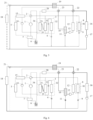
Fig. 1 is a schematic diagram of a heat pump air conditioning system according to an embodiment of the present disclosure. -
Fig. 2 is a schematic diagram of a heat pump air conditioning system in a standard heating mode according to an embodiment of the present disclosure. -
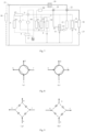
Fig. 3 is a schematic diagram of a heat pump air conditioning system in a cooling and fast charging mode according to an embodiment of the present disclosure. -
Fig. 4 is a schematic diagram of a heat pump air conditioning system in a heating and dehumidification mode according to an embodiment of the present disclosure. -
Fig. 5 is a schematic diagram of a heat pump air conditioning system in a mode where a battery and a passenger compartment are simultaneously heated according to an embodiment of the present disclosure. -
Fig. 6 is a schematic diagram of a heat pump air conditioning system in a cooling mode according to an embodiment of the present disclosure. -
Fig. 7 is a schematic diagram of a heat pump air conditioning system in a waste heat recovery mode according to an embodiment of the present disclosure. -
Fig. 8 is a schematic diagram of a reversing valve assembly of a heat pump air conditioning system according to some embodiments of the present disclosure. -
Fig. 9 is a schematic diagram of a reversing valve assembly of a heat pump air conditioning system according to some other embodiments of the present disclosure. - References signs:
1 compressor; 2 reversing valve assembly; 3 front air conditioning unit; 31 first heat exchanger; 32 second heat exchanger; 33 electronic fully-flow throttle valve; 34 warm air core; 35 warm air damper; 4 first throttling component; 5 external heat exchanger; 6 gas-liquid separator; 7 intermediate heat exchanger; 8 rear air conditioning unit; 81 third heat exchanger; 9 second throttling component; 10 battery heat exchanger; 11 third throttling component; 12 battery; 13 first water pump; 14 second water pump; 15 water-cooled condenser; 16 electric drive assembly; 17 third water pump; 18 external radiator; 19 water-to-water heat exchanger; 20 heater; 21 three-way water valve; 22 first four-way water valve; 23 second four-way water valve. - In order to more clearly understand the purpose, features and advantages of the present disclosure, embodiments of the present disclosure will be further described below. It should be noted that the embodiments of the present disclosure and the features in the embodiments may be combined with each other without conflict.
- In order to fully understand the present disclosure, many specific details are explained in the following description, but the present disclosure may also be implemented in other ways different from those described here; obviously, the embodiments in the description are only a part of embodiments of the present disclosure, not all of them.
- As shown in
Figures. 1 to 7 , some embodiments of the present disclosure provide a heat pump air conditioning system, including a refrigerant subsystem. In some specific embodiments, the refrigerant subsystem may use carbon dioxide as a refrigerant. The carbon dioxide refrigerant has a strong heating capacity to meet the heating requirements for a passenger compartment under a low-temperature heating condition. Of course, the refrigerant subsystem is not limited to using carbon dioxide as the refrigerant, and R22 refrigerant, R410A refrigerant, etc. may also be used. - In some specific embodiments, as illustrated in
Fig. 1 , the refrigerant subsystem includes acompressor 1, areversing valve assembly 2, a frontair conditioning unit 3, afirst throttling component 4, and anexternal heat exchanger 5 interconnected by means of refrigerant pipelines. The frontair conditioning unit 3 includes afirst heat exchanger 31. Thereversing valve assembly 2 includes four connection ports, namely a first connection port, a second connection port, a third connection port, and a fourth connection port. The first connection port is connected to a discharge port of thecompressor 1, the second connection port is connected to thefirst heat exchanger 31, the third connection port is connected to theexternal heat exchanger 5, and the fourth connection port is connected to a suction port of thecompressor 1. Thefirst throttling component 4 is located on a refrigerant pipeline where the frontair conditioning unit 3 is located, and is connected between thefirst heat exchanger 31 and theexternal heat exchanger 5. Thefirst throttling component 4 may specifically be a first electronic expansion valve, or of course, a first capillary tube, etc. - It should be understood that the front
air conditioning unit 3 is an air conditioning unit configured to deliver airflow to a front passenger compartment. - The heat pump air conditioning system provided in embodiments of the present disclosure may utilize the
reversing valve assembly 2 to switch a flow direction of the refrigerant in the refrigerant subsystem by providing thereversing valve assembly 2 in the refrigerant subsystem. In some specific embodiments, in a heating mode, the first connection port of thereversing valve assembly 2 is in communication with the second connection port of thereversing valve assembly 2, the third connection port of thereversing valve assembly 2 is in communication with the fourth connection port of thereversing valve assembly 2, and thecompressor 1, thefirst heat exchanger 31, thefirst throttling component 4, and theexternal heat exchanger 5 are sequentially communicated, thereby forming a refrigerant circulation circuit. In a cooling mode, the first connection port of the reversingvalve assembly 2 is in communication with the third connection port of the reversingvalve assembly 2, the second connection port of the reversingvalve assembly 2 is in communication with the fourth connection port of the reversingvalve assembly 2, and thecompressor 1, theexternal heat exchanger 5, thefirst throttling component 4, and thefirst heat exchanger 31 are sequentially communicated, thereby forming another refrigerant circulation circuit. Thus, the refrigerant subsystem not only may be utilized to cool the passenger compartment, but also may be utilized to heat the passenger compartment. The needs of both the heating mode and the cooling mode are realized by the refrigerant circuits, thus the system is simplified and costs are greatly reduced. - In some embodiments, as illustrated in
Fig. 1 , the frontair conditioning unit 3 further includes asecond heat exchanger 32 connected in series with thefirst heat exchanger 31. Thefirst throttling component 4 is connected between thesecond heat exchanger 32 and theexternal heat exchanger 5. By connecting two heat exchangers in series inside the frontair conditioning unit 3, the two heat exchangers simultaneously serve as heating cores under the low-temperature heating condition, effectively increasing a heat exchange area between the heat exchangers and the air flowing through the frontair conditioning unit 3, thereby significantly improving the heating energy efficiency of the heat pump air conditioning system in a low-temperature environment, and solving the problem of the low heating efficiency and the serious impact on a driving range of a vehicle caused by an existing heat pump air conditioning system relying on PTC heating in the low-temperature environment. - Specifically, the existing heat pump air conditioning system typically only uses the refrigerant subsystem to directly cool the passenger compartment. However, for heating the passenger compartment, the refrigerant subsystem is usually used to exchange heat with a water circuit subsystem, or a PTC heater provided in a water circuit is directly used to heat the passenger compartment. This heating method results in low heating energy efficiency of the heat pump air conditioning system. The heat pump air conditioning system provided in embodiments of the present disclosure may not only use the refrigerant subsystem to directly cool the passenger compartment, but also achieve using the refrigerant subsystem to directly heat the passenger compartment by providing the reversing
valve assembly 2 to switch the flow direction of the refrigerant in the refrigerant subsystem. Furthermore, in the heating mode, the two heat exchangers in the frontair conditioning unit 3 simultaneously serve as heating cores, effectively improving the heating energy efficiency. In the cooling mode, the two heat exchangers in the frontair conditioning unit 3 simultaneously serve as cooling cores, effectively improving cooling energy efficiency. Thus, the cooling and heating energy efficiency of the heat pump air conditioning system are effectively improved, effectively improving the driving range of the vehicle. - In some specific embodiments, the
first throttling component 4 may adopt a two-way electronic expansion valve. Thefirst throttling component 4 is located between a condenser and an evaporator. A high-pressure liquid refrigerant flowing out of the condenser instantly decreases in pressure and transforms into a low-pressure liquid refrigerant after passing through thefirst throttling component 4, and the low-pressure liquid refrigerant vaporizes into a gaseous refrigerant in the evaporator. By switching the flow direction of the refrigerant in the refrigerant subsystem through the reversingvalve assembly 2, the switching between the cooling mode and the heating mode may be achieved. - As shown in
Fig. 2 , in the heating mode, thecompressor 1, the reversingvalve assembly 2, thefirst heat exchanger 31, thesecond heat exchanger 32, thefirst throttling component 4, theexternal heat exchanger 5, and a gas-liquid separator 6 are sequentially connected to form a heating circuit for the passenger compartment. A high-temperature and high-pressure refrigerant gas discharged from thecompressor 1 enters the frontair conditioning unit 3 after passing through the reversingvalve assembly 2, and then sequentially flows through thefirst heat exchanger 31 and thesecond heat exchanger 32. At this time, thefirst heat exchanger 31 and thesecond heat exchanger 32 simultaneously serve as condensers (or called heating cores), liquefying the high-temperature and high-pressure refrigerant gas into a liquid. During the refrigerant liquefaction process, a large amount of heat is released, which heats the in-vehicle air entering the frontair conditioning unit 3, effectively ensuring the heating effect of the heat pump air conditioning system on the air in the passenger compartment. Then, a liquefied refrigerant liquid flows through thefirst throttling component 4 for pressure reduction, and a pressure of the refrigerant instantly decreases after the refrigerant flows out of thefirst throttling component 4. A low-pressure refrigerant liquid enters the external heat exchanger 5 (which serves as an evaporator at this time), the refrigerant liquid evaporates and vaporizes into a refrigerant gas by absorbing heat, and simultaneously absorbs the heat from outdoor air. A gaseous refrigerant re-enters the compressor to begin a next cycle. - As shown in
Fig. 6 , in the cooling mode, the flow direction of the refrigerant in the refrigerant subsystem is switched through the reversingvalve assembly 2, thecompressor 1, the reversingvalve assembly 2, theexternal heat exchanger 5, thefirst throttling component 4, thesecond heat exchanger 32, thefirst heat exchanger 31, and the gas-liquid separator 6 are sequentially connected to form a cooling circuit for the passenger compartment. The high-temperature and high-pressure refrigerant gas discharged from thecompressor 1 enters the external heat exchanger 5 (which serves as a condenser at this time) after passing through the reversingvalve assembly 2, where the high-temperature and high-pressure refrigerant gas is liquefied into a liquid. During this process, the refrigerant releases a significant amount of heat to the outdoor environment. Then, a liquefied refrigerant flows through thefirst throttling component 4 for pressure reduction, and a pressure of the refrigerant instantly decreases after the refrigerant flows out of thefirst throttling component 4. A low-pressure refrigerant liquid enters the frontair conditioning unit 3, and sequentially flows through thefirst heat exchanger 31 and thesecond heat exchanger 32. At this time, thefirst heat exchanger 31 and thesecond heat exchanger 32 simultaneously serve as evaporators (or called cooling cores), where the refrigerant liquid evaporates and vaporizes into a refrigerant gas by absorbing heat, and simultaneously absorbs the heat from the air inside the passenger compartment. This effectively ensures the cooling effect of the heat pump air conditioning system on the air inside the passenger compartment. A gaseous refrigerant then re-enters the compressor to begin a next cycle. - In some embodiments, as shown in
Fig. 1 , the refrigerant subsystem further includes a rearair conditioning unit 8 and asecond throttling component 9 connected through refrigerant pipelines. The rearair conditioning unit 8 includes athird heat exchanger 81 connected in parallel with the frontair conditioning unit 3. Thesecond throttling component 9 is located on a refrigerant pipeline where the rearair conditioning unit 8 is located, and is connected between thethird heat exchanger 81 and theexternal heat exchanger 5. Thesecond throttling component 9 may specifically be a second electronic expansion valve, or of course, a second capillary tube, etc. - It should be understood that the rear
air conditioning unit 8 is an air conditioning unit configured to deliver airflow to a rear passenger compartment. - In some specific embodiments, the
second throttling component 9 may adopt a two-way electronic expansion valve, and the flow direction of the refrigerant in the refrigerant subsystem is switched through the reversingvalve assembly 2, so as to achieve the switching between the cooling mode and the heating mode. Therefore, by changing the flow direction of the refrigerant in the refrigerant pipeline where thethird heat exchanger 81 in the rearair conditioning unit 8 is located, the refrigerant subsystem not only may be used to achieve cooling of the rearair conditioning unit 8 in the cooling mode (as shown inFig. 6 ), but also may be used to achieve heating of the rearair conditioning unit 8 in the heating mode (as shown inFig. 2 ). There is no need to arrange anadditional heater 20 or introduce a high temperature coolant from a front end for heating the rearair conditioning unit 8, thereby effectively simplifying the pipeline structure of the heat pump air conditioning system. - In some embodiments, as shown in
Fig. 1 , the refrigerant subsystem further includes abattery heat exchanger 10 and athird throttling component 11 connected through refrigerant pipelines. Thebattery heat exchanger 10 is connected in parallel with the frontair conditioning unit 3, and thethird throttling component 11 is located on a refrigerant pipeline where thebattery heat exchanger 10 is located, and is connected between thebattery heat exchanger 10 and theexternal heat exchanger 5. Thethird throttling component 11 may specifically be a third electronic expansion valve, or of course, a third capillary tube, etc. - In some specific embodiments, the
third throttling component 11 may adopt a two-way electronic expansion valve, and the flow direction of the refrigerant in the refrigerant subsystem is switched through the reversingvalve assembly 2, so as to achieve the switching between the cooling mode and the heating mode. Therefore, by changing the flow direction of the refrigerant in the refrigerant pipeline where thebattery heat exchanger 10 is located, the refrigerant subsystem not only may be used to achieve cooling of the battery heat exchanger 10 (as shown inFig. 3 andFig. 6 ), but also may be used to achieve heating of the battery heat exchanger 10 (as shown inFig. 2 ), thereby meeting the needs of cooling and heating of abattery 12. There is no need to arrange theadditional heater 20 or to introduce the high-temperature coolant from the front end for heating thebattery 12, thereby effectively simplifying the pipeline structure of the heat pump air conditioning system. - In some embodiments, as shown in
Fig. 1 , the heat pump air conditioning system further includes a water circuit subsystem, the water circuit subsystem includes a battery water circuit having afirst water pump 13, thebattery heat exchanger 10 is connected in the battery water circuit, and thebattery heat exchanger 10 transfers the heat or cold generated by the refrigerant subsystem to the battery water circuit. - It should be noted that the fluid flowing in the water circuit is not limited to water, but may also be other cooling liquids with good cold or heat storage capabilities. The
battery heat exchanger 10 is simultaneously connected to the refrigerant subsystem and the battery water circuit. In other words, thebattery heat exchanger 10 includes a set of refrigerant inlet and outlet and a set of coolant inlet and outlet. Specifically, the refrigerant inlet and outlet are configured to be connected to the refrigerant circuit, and the coolant inlet and outlet are configured to be connected to the battery water circuit. - In some specific embodiments, when it is necessary to cool the
battery 12, as shown inFigs. 3 and6 , the refrigerant circuit where thebattery heat exchanger 10 is located is in the cooling mode, and thebattery heat exchanger 10 serves as an evaporator to absorb heat from the battery water circuit, thereby achieving cooling of thebattery 12; when it is necessary to heat thebattery 12, as shown inFig. 1 , the refrigerant circuit where thebattery heat exchanger 10 is located is in the heating mode, and thebattery heat exchanger 10 serves as a condenser to release heat into the battery water circuit, thereby achieving heating of thebattery 12. - In some embodiments, as shown in
Fig. 1 , the water circuit subsystem further includes a warm air circuit having asecond water pump 14, a water-cooledcondenser 15, and awarm air core 34. The water-cooledcondenser 15 is connected in the refrigerant subsystem and located between theexternal heat exchanger 5 and the reversingvalve assembly 2. Thewarm air core 34 is located in the frontair conditioning unit 3, and awarm air damper 35 is provided between thewarm air core 34 and thefirst heat exchanger 31. - It should be noted that the water-cooled
condenser 15 is simultaneously connected in the warm air circuit and the refrigerant subsystem. In other words, the water-cooledcondenser 15 includes a set of refrigerant inlet and outlet and a set of coolant inlet and outlet. Specifically, the refrigerant inlet and outlet are configured to be connected to the refrigerant circuit, and the coolant inlet and outlet are configured to be connected to the warm air circuit. - In the above embodiments, by providing the warm air circuit, the
warm air core 34 of the warm air circuit may be utilized to adjust the temperature, humidity, etc., of the air in the frontair conditioning unit 3. By arranging thewarm air damper 35 between thewarm air core 34 and thefirst heat exchanger 31, thewarm air core 34 and thefirst heat exchanger 31 are separated when thewarm air damper 35 is closed, avoiding mutual interference between thewarm air core 34 and thefirst heat exchanger 31. When thewarm air damper 35 is opened, thewarm air core 34, thefirst heat exchanger 31, and thesecond heat exchanger 32 may be utilized to collectively regulate the temperature, humidity, etc., of the air flowing through the frontair conditioning unit 3. - In some embodiments, as shown in
Fig. 1 , the water circuit subsystem further includes a motor cooling water circuit having athird water pump 17, anexternal radiator 18, and a water-to-water heat exchanger 19. The water-to-water heat exchanger 19 is connected in the warm air circuit and transfers the heat generated by the warm air circuit to the motor cooling water circuit. - It should be noted that the water-to-
water heat exchanger 19 is connected in both the motor cooling water circuit and the warm air circuit. In other words, the water-to-water heat exchanger 19 includes two sets of coolant inlets and outlets. Specifically, one set of coolant inlet and outlet are configured to be connected to the warm air circuit, and the other set of coolant inlet and outlet are configured to be connected to the motor cooling water circuit. - In the above embodiments, by providing the water-to-
water heat exchanger 19 in the warm air circuit and the motor cooling water circuit, in a cooling and fast charging mode, as shown inFig. 3 , the battery water circuit provides heat dissipation for the battery through water circulation. At this time, thebattery heat exchanger 10 serves as an evaporator, transferring the heat in the battery water circuit to the refrigerant subsystem. The water-cooledcondenser 15 transfers the heat generated by the refrigerant subsystem to the warm air circuit, then a part of the heat generated by the water-cooledcondenser 15 during a cooling process is transferred to the motor cooling water circuit through the water-to-water heat exchanger 19 (at this time, a motor is inactive and has no cooling demand), and then the idle motor cooling water circuit is utilized to discharge the part of the heat generated by the water-cooledcondenser 15 to the air outside the vehicle, thereby facilitating the improvement of the condensation capacity of the water-cooledcondenser 15, meeting the high cooling demand in the fast charging mode, and achieving the goal of rapidly dissipating heat from the battery. - In some embodiments, as shown in
Fig. 1 , the water circuit subsystem further includes a waste heat recovery water circuit. The waste heat recovery water circuit is connected in parallel with the motor cooling water circuit through a three-way water valve 21. The three-way water valve 21 controls anelectric drive assembly 16 to be connected to one of the motor cooling water circuit and the waste heat recovery water circuit. - In the above embodiments, by providing the waste heat recovery water circuit, the heat generated by the
electric drive assembly 16 may be recovered and utilized. For example, in the heating mode, the heat produced by theelectric drive assembly 16 may be utilized to heat the water-cooled condenser 15 (which serves as an evaporator at this time), thereby enhancing the heating capacity of the water-cooledcondenser 15. - Specifically, in the cooling mode (as shown in
Fig. 6 ) as well as the cooling and fast charging mode (as shown inFig. 3 ), the three-way water valve 21 may control theelectric drive assembly 16 to be connected to the motor cooling water circuit. In a waste heat recovery mode (as shown inFig. 7 ), the three-way water valve 21 may control theelectric drive assembly 16 to be connected to the waste heat recovery water circuit. In specific implementation, the motor cooling water circuit and the waste heat recovery water circuit may share a section of water pipeline. The electric drive assembly 16 (which may specifically include a motor, an inverter, etc.), thethird water pump 17, and the water-to-water heat exchanger 19 are arranged on the shared section of water pipeline. Theexternal radiator 18 is arranged on a section of water pipeline not shared by the motor cooling water circuit and the waste heat recovery water circuit, and no additional components are provided on the section of water pipeline not shared by the motor cooling water circuit and the waste heat recovery water circuit. As such, by switching valve ports of the three-way water valve 21, theelectric drive assembly 16 is controlled to be connected to one of the motor cooling water circuit and the waste heat recovery water circuit. - In some embodiments, as shown in
Fig. 1 , the motor cooling water circuit is interconnected with the battery water circuit through a first four-way water valve 22. The first four-way water valve 22 controls one of the motor cooling water circuit and the waste heat recovery water circuit to operate independently of or be communicated with a battery cooling water circuit. For example, in the cooling mode as well as in the cooling and fast charging mode, the motor cooling water circuit and the battery cooling water circuit may be controlled to be independent of each other through the first four-way water valve 22. In the heating mode, the waste heat recovery water circuit and the battery cooling water circuit may be controlled to be independent of each other through the first four-way water valve 22. In the waste heat recovery mode, the waste heat recovery water circuit and the battery cooling water circuit may be controlled to be communicated with each other through the first four-way water valve 22. - In some embodiments, as shown in
Fig. 1 , the warm air circuit includes aheater 20, the warm air circuit is interconnected with the battery water circuit through a second four-way water valve 23, and the second four-way water valve 23 controls the warm air circuit and the battery water circuit to be independent of each other or be communicated with each other. For example, when the heating capacity of the battery is insufficient, the warm air circuit and the battery water circuit may be communicated with each other, and theheater 20 arranged in the warm air circuit may be utilized to heat the battery. Of course, an arrangement of theheater 20 is not limited to being arranged in the warm air circuit, but may also be arranged in the battery water circuit, or theheater 20 may be arranged in each of the warm air circuit and the battery water circuit as needed. In all the above cases, the purpose of using theheater 20 to provide auxiliary heating for the battery may be achieved. - In some embodiments, as shown in
Fig. 1 , the frontair conditioning unit 3 further includes an electronic full-flow throttle valve 33 connected between thefirst heat exchanger 31 and thesecond heat exchanger 32. - Specifically, when heating and dehumidification are required inside the front
air conditioning unit 3, as shown inFig. 4 , the electronic full-flow throttle valve 33 between thefirst heat exchanger 31 and thesecond heat exchanger 32 in the front air conditioning unit is in a throttling state, thesecond heat exchanger 32 is in a cooling and dehumidification mode, thefirst heat exchanger 31 is in the heating mode, and at the same time, theexternal heat exchanger 5 serves as an evaporator, thus meeting the needs of heating and dehumidification. In a specific implementation, the opening degree of thefirst throttling component 4 between thesecond heat exchanger 32 and theexternal heat exchanger 5 may be determined based on the actual air state. If the ambient temperature is very low, the opening degree of thefirst throttling component 4 is adjusted to be small, ensuring that heat may be absorbed from theexternal heat exchanger 5, and the temperature of the refrigerant in thesecond heat exchanger 32 is not lower than zero degrees, preventing the surface of fins of thesecond heat exchanger 32 from freezing and hindering air circulation. - In some embodiments, as shown in
Fig. 1 , the refrigerant subsystem further includes anintermediate heat exchanger 7 connected between theexternal heat exchanger 5 and the suction port of thecompressor 1, i.e. located on a side away from the reversingvalve assembly 2. Theintermediate heat exchanger 7 is connected to a refrigerant pipeline on a suction port side of thecompressor 1, to provide the cooling and heating capabilities of the refrigerant subsystem by arranging theintermediate heat exchanger 7. - The heat pump air conditioning system provided in the above embodiments of the present disclosure may achieve a plurality of different working modes. The working modes of the heat pump air conditioning system may include the standard heating mode, the cooling mode, the cooling and fast charging mode, the heating and dehumidification mode, a mode where the battery and the passenger compartment are simultaneously heated, and the waste heat recovery mode, etc.
- In the standard heating mode, as shown in
Fig. 2 , the passenger compartment is heated. The two heat exchangers in the frontair conditioning unit 3 heat the air flowing through the frontair conditioning unit 3, achieving the heating demand for the passenger compartment, improving the heating rate and energy efficiency, and simplifying control. Moreover, the refrigerant subsystem may also be utilized to heat the rearair conditioning unit 8, without the need for additional PTC (APTC) heating or specially introducing the high-temperature coolant from the front end to heat the rearair conditioning unit 8. - In the cooling and fast charging mode of the battery, as shown in
Fig. 3 , the refrigerant subsystem is used to cool the battery water circuit where the battery is located. At the same time, theexternal radiator 18 and the water-to-water heat exchanger 19 form the motor cooling circuit, which works together with the water-cooledcondenser 15 in the warm air circuit, to achieve cooling of the high-temperature and high-pressure refrigerant, effectively improving the cooling capacity of the water-cooledcondenser 15, and enhancing the cooling capacity of the battery. At this time, thewarm air damper 35 inside the frontair conditioning unit 3 is in a closed state, ensuring that the air in the frontair conditioning unit 3 does not pass through thewarm air core 34. - In the heating and dehumidification mode, as shown in
Fig. 4 , the electronic full-flow throttle valve 33 between thefirst heat exchanger 31 and thesecond heat exchanger 32 in the front air conditioning unit is in the throttling state, thesecond heat exchanger 32 is in a cooling and dehumidification mode, thefirst heat exchanger 31 is in the heating mode, and at the same time, theexternal heat exchanger 5 serves as an evaporator, thus meeting the needs of heating and dehumidification. In a specific implementation, the opening degree of thefirst throttling component 4 between thesecond heat exchanger 32 and theexternal heat exchanger 5 may be determined based on the actual air state. If the ambient temperature is very low, the opening degree of thefirst throttling component 4 is adjusted to be small, ensuring that heat may be absorbed from theexternal heat exchanger 5, and the temperature of the refrigerant in thesecond heat exchanger 32 is not lower than zero degrees, preventing the surface of fins of thesecond heat exchanger 32 from freezing and hindering air circulation. - In the mode where the battery and the passenger compartment are simultaneously heated, as shown in
Fig. 5 , the high-temperature and high-pressure refrigerant from thecompressor 1 directly enters the two heat exchangers in the frontair conditioning unit 3, the heat exchanger in the rearair conditioning unit 8, and thebattery heat exchanger 10 after passing through the reversingvalve assembly 2. At this time, the two heat exchangers in the frontair conditioning unit 3 serves as condensers to heat the air in the frontair conditioning unit 3, the heat exchanger in the rearair conditioning unit 8 serves as a condenser to heat the air in the rearair conditioning unit 8, and thebattery heat exchanger 10 serves as a condenser to heat the water for the battery. If the heating capacity of the battery is insufficient, theheater 20 in the warm air circuit may be activated. The warm air circuit is connected in series with the battery water circuit through the four-way water valve. Alternatively, theheater 20 of the warm air circuit is utilized to heat thewarm air core 34 in the frontair conditioning unit 3, and the water-cooled condenser 15 (which serves as an evaporator at this time) is utilized to heat the refrigerant, improving the heat absorption capacity on a low-pressure side of the heat pump and ultimately achieving rapid heating of the battery. At this time, theheater 20 and thecompressor 1 work together, and the heat is absorbed from the air, so that three parts of heat heats the coolant in the battery water circuit to meet the heating requirements for the battery. - It should be noted that the
PTC heater 20 may be arranged in the warm air circuit, or in the battery water circuit. In addition, by utilizing motor stall to generate heat, the power of theheater 20 may be minimized or eliminated. - In the cooling mode, as shown in
Fig. 6 , the two heat exchangers in the front air conditioning unit work as evaporators simultaneously. At this time, the electronic full-flow throttle valve 33 between the two heat exchangers is in a full-flow mode, and the frontair conditioning unit 3, the rearair conditioning unit 8, and the battery are in a parallel mode. Similarly, the water-to-water heat exchanger 19 in the motor cooling water circuit is used to cool the liquid in the water-cooledcondenser 15 in the warm air circuit, thereby improving the cooling capacity of the refrigerant on a high-pressure side. - In addition, in another scenario, such as an environmental condition of 15-20 °C, the cooling and dehumidification mode is required in the passenger compartment. The two heat exchangers in the front
air conditioning unit 3 are used as evaporators to achieve cooling simultaneously, while the water-cooledcondenser 15 generates heat to heat thewarm air core 34, thereby achieving the purpose of cooling and dehumidification. In some embodiments, a dual temperature zone control of the frontair conditioning unit 3 may be achieved by using thewarm air damper 35 between thewarm air core 34 and thefirst heat exchanger 31. - In the waste heat recovery mode, as shown in
Fig. 7 , the battery water circuit and the waste heat recovery water circuit are communicated with each other through the first four-way water valve 22, to use the heat generated by the motor and the battery in a working process to heat the water-cooled condenser 15 (which serves as an evaporator at this time), thereby improving the heating capacity of the water-cooledcondenser 15 and achieving energy recovery and utilization. - It should be noted that the reversing
valve assembly 2 may specifically adopt a four-way reversing valve, or a valve assembly composed of four shut-off valves. In other words, in the schematic diagrams of the above system, it is described that the four-way reversing valve is adopted to switch the refrigerant on the high-pressure and low-pressure sides of the refrigerant subsystem, achieving the purpose of cooling and heating. The four-way reversing valve is not the only means, and it may be replaced by the four shut-off valves, which may also achieve the purpose of cooling and heating. - In some embodiments, as shown in
Fig. 8 , the reversingvalve assembly 2 includes the four-way reversing valve. - In other embodiments, as shown in
Fig. 9 , the reversingvalve assembly 2 includes the four shut-off valves respectively arranged on four pipe segments connected end to end in sequence. The cooling mode and the heating mode are switched by opening two of the four shut-off valves and closing the other two of the four shut-off valves. - In summary, the heat pump air conditioning system provided in the embodiments of the present disclosure has at least the following technical effects.
- 1) Taking advantage of the strong heating capacity of carbon dioxide, the carbon dioxide refrigerant is used to simultaneously heat the battery and air conditioning units. By combining the heat exchangers and valves, the optimal combination for switching between a plurality of modes is achieved, improving cooling and heating efficiency.
- 2) The heat pump air conditioning system adopts a direct heat pump system, which directly heats and cools the air, and directly exchanges heat with the ambient air to improve the energy efficiency and capacity of the system.
- 3) By utilizing the two heat exchangers in the front air conditioning unit to simultaneously serve as cooling cores or heating cores, the area of the heat exchangers is better increased, thereby enhancing the cooling and heating capabilities and improving the energy efficiency of the system.
- 4) By adjusting the power of the warm air circuit and the heater, as well as combining the water-cooled condenser and the water-to-water heat exchanger, and fully utilizing the external radiator in the motor cooling water circuit, various combinations of cooling and heating functions are achieved, especially the cooling and fast charging mode of the battery.
- 5) Utilizing the carbon dioxide refrigerant to directly heat the battery heat exchanger, the heating of the battery is achieved. The heating of a rear air conditioner is achieved through the third heat exchanger in the rear air conditioner and the second electronic expansion valve with two-way full flow, thus reducing the cost.
- 6) By using the four-way reversing valve to switch the cooling mode and the heating mode, the complexity of a refrigerant side of the system may be greatly reduced, and the risk of sealing leakage may be reduced.
- Other embodiments of the present disclosure provide a vehicle including the heat pump air conditioning system according to any one of the above embodiments.
- The vehicle provided in the embodiments of the present disclosure has the beneficial effects of the heat pump air conditioning system in any one of the above embodiments as it includes the heat pump air conditioning system in any one of the above embodiments, which will not be repeated here.
- It should be noted that in the present disclosure, relative terms such as "first" and "second" are only used to distinguish one entity or operation from another entity or operation, and do not necessarily require or imply any such actual relationship or order between these entities or operations. Furthermore, the term "include", "comprise" or any other variation thereof is intended to cover non-exclusive inclusions such that a process, method, article, or device comprising/including a series of elements includes not only those elements, but also other elements that are not expressly listed, or also includes elements inherent in such process, method, article, or device. Without further limitation, an element defined by the phrase "comprising/including a ..." does not exclude the presence of additional identical elements in the process, method, article or device comprising/including the element.
- The above description only relates to specific embodiments of the present disclosure, so that those skilled in the art may understand or implement the present disclosure. Various modifications to these embodiments will be apparent to those skilled in the art, and the general principles defined herein may be implemented in other embodiments without departing from the spirit or scope of the present disclosure. Therefore, the present disclosure will not be limited to the embodiments described herein, but is to be accorded the widest scope consistent with the principles and novel features disclosed herein.
Claims (14)
- A heat pump air conditioning system, comprising a refrigerant subsystem;the refrigerant subsystem comprising a compressor, a reversing valve assembly, a front air conditioning unit, a first throttling component, and an external heat exchanger connected through refrigerant pipelines, the front air conditioning unit comprising a first heat exchanger;the reversing valve assembly comprising four connection ports, wherein a first connection port is connected to a discharge port of the compressor, a second connection port is connected to the first heat exchanger, a third connection port is connected to the external heat exchanger, and a fourth connection port is connected to a suction port of the compressor;wherein, in a heating mode, the first connection port is in communication with the second connection port, the third connection port is in communication with the fourth connection port, and the compressor, the first heat exchanger, the first throttling component, and the external heat exchanger are sequentially connected to form a refrigerant circulation circuit; andin a cooling mode, the first connection port is in communication with the third connection port, the second connection port is in communication with the fourth connection port, and the compressor, the external heat exchanger, the first throttling component, and the first heat exchanger are sequentially connected to form another refrigerant circulation circuit.
- The heat pump air conditioning system according to claim 1, wherein the front air conditioning unit further comprises a second heat exchanger connected in series with the first heat exchanger, and the first throttling component is connected between the second heat exchanger and the external heat exchanger.
- The heat pump air conditioning system according to claim 2, wherein the front air conditioning unit further comprises an electronic full-flow throttle valve connected between the first heat exchanger and the second heat exchanger.
- The heat pump air conditioning system according to any one of claims 1 to 3, wherein the refrigerant subsystem further comprises a rear air conditioning unit and a second throttling component connected through refrigerant pipelines, the rear air conditioning unit comprises a third heat exchanger connected in parallel with the front air conditioning unit, and the second throttling component is connected between the third heat exchanger and the external heat exchanger.
- The heat pump air conditioning system according to any one of claims 1 to 4, wherein the refrigerant subsystem further comprises a battery heat exchanger and a third throttling component connected through refrigerant pipelines, the battery heat exchanger is connected in parallel with the front air conditioning unit, and the third throttling component is connected between the battery heat exchanger and the external heat exchanger.
- The heat pump air conditioning system according to claim 5, further comprising a water circuit subsystem, wherein the water circuit subsystem comprises a battery water circuit having a first water pump, the battery heat exchanger is connected in the battery water circuit, and the battery heat exchanger transfers heat or cold generated by the refrigerant subsystem to the battery water circuit.
- The heat pump air conditioning system according to claim 6, wherein the water circuit subsystem further comprises a warm air circuit, the warm air circuit comprises a second water pump, a water-cooled condenser, and a warm air core, the water-cooled condenser is connected in the refrigerant subsystem and located between the external heat exchanger and the reversing valve assembly, the warm air core is located in the front air conditioning unit, and a warm air damper is provided between the warm air core and the first heat exchanger.
- The heat pump air conditioning system according to claim 7, wherein the water circuit subsystem further comprises a motor cooling water circuit, the motor cooling water circuit comprises a third water pump, an external radiator, and a water-to-water heat exchanger, and the water-to-water heat exchanger is connected in the warm air circuit and transfers heat generated by the warm air circuit to the motor cooling water circuit.
- The heat pump air conditioning system according to claim 8, wherein the water circuit subsystem further comprises a waste heat recovery water circuit, the waste heat recovery water circuit is connected in parallel with the motor cooling water circuit through a three-way water valve, and the three-way water valve controls an electric drive assembly to be connected to one of the motor cooling water circuit and the waste heat recovery water circuit.
- The heat pump air conditioning system according to claim 9, wherein the motor cooling water circuit is interconnected with the battery water circuit through a first four-way water valve, and the first four-way water valve controls the one of the motor cooling water circuit and the waste heat recovery water circuit to be independent of or be communicated with the battery water circuit.
- The heat pump air conditioning system according to any one of claims 7 to 10, wherein the warm air circuit and/or the battery water circuit comprises a heater, the warm air circuit is interconnected with the battery water circuit through a second four-way water valve, and the second four-way water valve controls the warm air circuit and the battery water circuit to be independent of each other or be communicated with each other.
- The heat pump air conditioning system according to any one of claims 1 to 11, wherein the refrigerant subsystem further comprises an intermediate heat exchanger connected between the external heat exchanger and the suction port of the compressor.
- The heat pump air conditioning system according to any one of claims 1 to 12, wherein the reversing valve assembly comprises a four-way reversing valve; or
the reversing valve assembly comprises four shut-off valves respectively arranged on four pipe segments connected end to end in sequence, and a corresponding connection port is arranged at a joint of each two adjacent pipe segments. - A vehicle, comprising a heat pump air conditioning system according to any one of claims 1-13.
Applications Claiming Priority (2)
| Application Number | Priority Date | Filing Date | Title |
|---|---|---|---|
| CN202210893741.1A CN117507761A (en) | 2022-07-27 | 2022-07-27 | Heat pump air conditioning systems and vehicles |
| PCT/CN2023/109619 WO2024022451A1 (en) | 2022-07-27 | 2023-07-27 | Heat pump air-conditioning system, and vehicle |
Publications (2)
| Publication Number | Publication Date |
|---|---|
| EP4563375A1 true EP4563375A1 (en) | 2025-06-04 |
| EP4563375A4 EP4563375A4 (en) | 2025-11-19 |
Family
ID=89705479
Family Applications (1)
| Application Number | Title | Priority Date | Filing Date |
|---|---|---|---|
| EP23845658.6A Pending EP4563375A4 (en) | 2022-07-27 | 2023-07-27 | HEAT PUMP AIR CONDITIONING SYSTEM AND VEHICLE |
Country Status (3)
| Country | Link |
|---|---|
| EP (1) | EP4563375A4 (en) |
| CN (1) | CN117507761A (en) |
| WO (1) | WO2024022451A1 (en) |
Families Citing this family (1)
| Publication number | Priority date | Publication date | Assignee | Title |
|---|---|---|---|---|
| CN119408374B (en) * | 2024-12-11 | 2026-01-02 | 奇瑞汽车股份有限公司 | A heat pump air conditioning system and a vehicle having the heat pump air conditioning system |
Family Cites Families (15)
| Publication number | Priority date | Publication date | Assignee | Title |
|---|---|---|---|---|
| KR100225262B1 (en) * | 1997-01-14 | 1999-10-15 | 홍순택 | A device of air conditioner combined use heater for heavy equipnent |
| JP2000161794A (en) * | 1998-11-27 | 2000-06-16 | Calsonic Corp | Air conditioner for vehicle |
| CN106274372B (en) * | 2016-11-14 | 2019-02-22 | 吉林大学 | Heat pump car air conditioner with battery thermal management |
| FR3061867B1 (en) * | 2017-01-17 | 2020-05-01 | Valeo Systemes Thermiques | CIRCULATION LOOP OF A REFRIGERANT FLUID FOR THE CONDITIONING OF INTERIOR AIR OF A VEHICLE |
| CN206436773U (en) * | 2017-02-10 | 2017-08-25 | 苏州赛普瑞新能源汽车空调有限公司 | A kind of air-conditioning system used for electric vehicle |
| CN108001157B (en) * | 2017-12-05 | 2023-10-31 | 珠海长欣汽车智能系统有限公司 | A battery box heating system |
| KR102637895B1 (en) * | 2018-08-10 | 2024-02-19 | 한온시스템 주식회사 | Heat management system of vehicle |
| US11214115B2 (en) * | 2019-06-03 | 2022-01-04 | Proterra Inc. | Temperature management systems and methods for electric vehicle |
| US20210188043A1 (en) * | 2019-12-23 | 2021-06-24 | Nio Usa, Inc. | Thermal management system topology with cascaded refrigerant and coolant circuits |
| CN112109521B (en) * | 2020-09-17 | 2022-04-22 | 东风汽车集团有限公司 | Whole-vehicle thermal management system of pure electric vehicle |
| US20230356564A1 (en) * | 2020-09-30 | 2023-11-09 | Sanhua Holding Group Co., Ltd. | Thermal management system with improved working efficiency of compressor |
| CN114312219B (en) * | 2021-12-31 | 2024-03-08 | 悠跑科技(合肥)有限公司 | Electric automobile air conditioning system and control method thereof |
| CN114379326B (en) * | 2022-03-01 | 2026-02-10 | 上海爱斯达克汽车空调系统有限公司 | Electric vehicle dual-flow thermal management system |
| CN114701325A (en) * | 2022-03-31 | 2022-07-05 | 东风汽车集团股份有限公司 | Pure electric vehicle whole vehicle thermal management system and control method |
| CN114683804B (en) * | 2022-04-15 | 2024-11-08 | 北京京深深向科技有限公司 | A multi-source heat pump system for electric vehicles |
-
2022
- 2022-07-27 CN CN202210893741.1A patent/CN117507761A/en active Pending
-
2023
- 2023-07-27 EP EP23845658.6A patent/EP4563375A4/en active Pending
- 2023-07-27 WO PCT/CN2023/109619 patent/WO2024022451A1/en not_active Ceased
Also Published As
| Publication number | Publication date |
|---|---|
| CN117507761A (en) | 2024-02-06 |
| EP4563375A4 (en) | 2025-11-19 |
| WO2024022451A1 (en) | 2024-02-01 |
Similar Documents
| Publication | Publication Date | Title |
|---|---|---|
| EP4151440B1 (en) | Heat management system | |
| US11760162B2 (en) | Thermal management system | |
| CN113415121B (en) | Thermal management system, control method thereof and electric automobile | |
| CN113173050B (en) | Thermal management system | |
| CN209365827U (en) | A kind of new-energy automobile vehicle waste heat recovery type heat pump air conditioning system | |
| CN107914538B (en) | Electric automobile thermal management system | |
| US20230356564A1 (en) | Thermal management system with improved working efficiency of compressor | |
| CN112140829A (en) | Vehicle thermal management system and vehicle | |
| CN111422027B (en) | Vehicle thermal management system and control method thereof | |
| CN113173049B (en) | Thermal management system | |
| EP3666565B1 (en) | Automotive air conditioning system | |
| CN113895205A (en) | An economical heat pump system with waste heat recovery | |
| CN114838517A (en) | Thermal management system and vehicle | |
| CN116552195A (en) | Heat pump type integrated heat management system utilizing motor waste heat | |
| CN107351623A (en) | Automotive thermal tube manages system and electric automobile | |
| CN219838412U (en) | Direct heat pump type heat management integrated module and system | |
| CN116653544B (en) | Multi-channel electronic water valve thermal management system assembly | |
| CN116061678A (en) | Vehicle thermal management system and vehicle | |
| EP4563375A1 (en) | Heat pump air-conditioning system, and vehicle | |
| EP4043250B1 (en) | Vehicle thermal management system, and vehicle | |
| CN212289436U (en) | Thermal management system and electric automobile | |
| CN115703321A (en) | thermal management system | |
| CN216139775U (en) | Electric vehicle and heat pump system thereof | |
| CN116638922A (en) | New energy thermal management system and thermal management method | |
| CN117507760A (en) | Heat pump air conditioning system and control method and vehicle thereof |
Legal Events
| Date | Code | Title | Description |
|---|---|---|---|
| STAA | Information on the status of an ep patent application or granted ep patent |
Free format text: STATUS: THE INTERNATIONAL PUBLICATION HAS BEEN MADE |
|
| PUAI | Public reference made under article 153(3) epc to a published international application that has entered the european phase |
Free format text: ORIGINAL CODE: 0009012 |
|
| STAA | Information on the status of an ep patent application or granted ep patent |
Free format text: STATUS: REQUEST FOR EXAMINATION WAS MADE |
|
| 17P | Request for examination filed |
Effective date: 20250227 |
|
| AK | Designated contracting states |
Kind code of ref document: A1 Designated state(s): AL AT BE BG CH CY CZ DE DK EE ES FI FR GB GR HR HU IE IS IT LI LT LU LV MC ME MK MT NL NO PL PT RO RS SE SI SK SM TR |
|
| DAV | Request for validation of the european patent (deleted) | ||
| DAX | Request for extension of the european patent (deleted) | ||
| A4 | Supplementary search report drawn up and despatched |
Effective date: 20251021 |
|
| RIC1 | Information provided on ipc code assigned before grant |
Ipc: B60H 1/32 20060101AFI20251015BHEP Ipc: B60H 1/00 20060101ALI20251015BHEP Ipc: B60H 1/04 20060101ALI20251015BHEP Ipc: B60K 11/04 20060101ALI20251015BHEP Ipc: B60L 58/26 20190101ALI20251015BHEP Ipc: B60L 58/27 20190101ALI20251015BHEP Ipc: B60H 3/02 20060101ALI20251015BHEP Ipc: B60K 1/00 20060101ALI20251015BHEP Ipc: B60K 11/02 20060101ALI20251015BHEP |