EP4563313A1 - Container manufacturing method, double container manufacturing method, double container, and method for discharging contents from double container - Google Patents
Container manufacturing method, double container manufacturing method, double container, and method for discharging contents from double container Download PDFInfo
- Publication number
- EP4563313A1 EP4563313A1 EP23846445.7A EP23846445A EP4563313A1 EP 4563313 A1 EP4563313 A1 EP 4563313A1 EP 23846445 A EP23846445 A EP 23846445A EP 4563313 A1 EP4563313 A1 EP 4563313A1
- Authority
- EP
- European Patent Office
- Prior art keywords
- preform
- main body
- inner bag
- container main
- container
- Prior art date
- Legal status (The legal status is an assumption and is not a legal conclusion. Google has not performed a legal analysis and makes no representation as to the accuracy of the status listed.)
- Pending
Links
Images














Classifications
-
- B—PERFORMING OPERATIONS; TRANSPORTING
- B29—WORKING OF PLASTICS; WORKING OF SUBSTANCES IN A PLASTIC STATE IN GENERAL
- B29C—SHAPING OR JOINING OF PLASTICS; SHAPING OF MATERIAL IN A PLASTIC STATE, NOT OTHERWISE PROVIDED FOR; AFTER-TREATMENT OF THE SHAPED PRODUCTS, e.g. REPAIRING
- B29C49/00—Blow-moulding, i.e. blowing a preform or parison to a desired shape within a mould; Apparatus therefor
- B29C49/071—Preforms or parisons characterised by their configuration, e.g. geometry, dimensions or physical properties
-
- B—PERFORMING OPERATIONS; TRANSPORTING
- B29—WORKING OF PLASTICS; WORKING OF SUBSTANCES IN A PLASTIC STATE IN GENERAL
- B29B—PREPARATION OR PRETREATMENT OF THE MATERIAL TO BE SHAPED; MAKING GRANULES OR PREFORMS; RECOVERY OF PLASTICS OR OTHER CONSTITUENTS OF WASTE MATERIAL CONTAINING PLASTICS
- B29B11/00—Making preforms
- B29B11/04—Making preforms by assembling preformed material
-
- B—PERFORMING OPERATIONS; TRANSPORTING
- B29—WORKING OF PLASTICS; WORKING OF SUBSTANCES IN A PLASTIC STATE IN GENERAL
- B29B—PREPARATION OR PRETREATMENT OF THE MATERIAL TO BE SHAPED; MAKING GRANULES OR PREFORMS; RECOVERY OF PLASTICS OR OTHER CONSTITUENTS OF WASTE MATERIAL CONTAINING PLASTICS
- B29B11/00—Making preforms
- B29B11/06—Making preforms by moulding the material
-
- B—PERFORMING OPERATIONS; TRANSPORTING
- B29—WORKING OF PLASTICS; WORKING OF SUBSTANCES IN A PLASTIC STATE IN GENERAL
- B29B—PREPARATION OR PRETREATMENT OF THE MATERIAL TO BE SHAPED; MAKING GRANULES OR PREFORMS; RECOVERY OF PLASTICS OR OTHER CONSTITUENTS OF WASTE MATERIAL CONTAINING PLASTICS
- B29B11/00—Making preforms
- B29B11/14—Making preforms characterised by structure or composition
-
- B—PERFORMING OPERATIONS; TRANSPORTING
- B29—WORKING OF PLASTICS; WORKING OF SUBSTANCES IN A PLASTIC STATE IN GENERAL
- B29C—SHAPING OR JOINING OF PLASTICS; SHAPING OF MATERIAL IN A PLASTIC STATE, NOT OTHERWISE PROVIDED FOR; AFTER-TREATMENT OF THE SHAPED PRODUCTS, e.g. REPAIRING
- B29C49/00—Blow-moulding, i.e. blowing a preform or parison to a desired shape within a mould; Apparatus therefor
- B29C49/02—Combined blow-moulding and manufacture of the preform or the parison
-
- B—PERFORMING OPERATIONS; TRANSPORTING
- B29—WORKING OF PLASTICS; WORKING OF SUBSTANCES IN A PLASTIC STATE IN GENERAL
- B29C—SHAPING OR JOINING OF PLASTICS; SHAPING OF MATERIAL IN A PLASTIC STATE, NOT OTHERWISE PROVIDED FOR; AFTER-TREATMENT OF THE SHAPED PRODUCTS, e.g. REPAIRING
- B29C49/00—Blow-moulding, i.e. blowing a preform or parison to a desired shape within a mould; Apparatus therefor
- B29C49/22—Blow-moulding, i.e. blowing a preform or parison to a desired shape within a mould; Apparatus therefor using multilayered preforms or parisons
-
- B—PERFORMING OPERATIONS; TRANSPORTING
- B29—WORKING OF PLASTICS; WORKING OF SUBSTANCES IN A PLASTIC STATE IN GENERAL
- B29C—SHAPING OR JOINING OF PLASTICS; SHAPING OF MATERIAL IN A PLASTIC STATE, NOT OTHERWISE PROVIDED FOR; AFTER-TREATMENT OF THE SHAPED PRODUCTS, e.g. REPAIRING
- B29C49/00—Blow-moulding, i.e. blowing a preform or parison to a desired shape within a mould; Apparatus therefor
- B29C49/42—Component parts, details or accessories; Auxiliary operations
- B29C49/42386—Improving flash formation, e.g. providing for easily removable flash from extrusion moulded articles
-
- B—PERFORMING OPERATIONS; TRANSPORTING
- B29—WORKING OF PLASTICS; WORKING OF SUBSTANCES IN A PLASTIC STATE IN GENERAL
- B29D—PRODUCING PARTICULAR ARTICLES FROM PLASTICS OR FROM SUBSTANCES IN A PLASTIC STATE
- B29D22/00—Producing hollow articles
- B29D22/003—Containers for packaging, storing or transporting, e.g. bottles, jars, cans, barrels, tanks
-
- B—PERFORMING OPERATIONS; TRANSPORTING
- B29—WORKING OF PLASTICS; WORKING OF SUBSTANCES IN A PLASTIC STATE IN GENERAL
- B29D—PRODUCING PARTICULAR ARTICLES FROM PLASTICS OR FROM SUBSTANCES IN A PLASTIC STATE
- B29D99/00—Subject matter not provided for in other groups of this subclass
- B29D99/0096—Producing closure members for containers, e.g. closure caps or stoppers
-
- B—PERFORMING OPERATIONS; TRANSPORTING
- B65—CONVEYING; PACKING; STORING; HANDLING THIN OR FILAMENTARY MATERIAL
- B65D—CONTAINERS FOR STORAGE OR TRANSPORT OF ARTICLES OR MATERIALS, e.g. BAGS, BARRELS, BOTTLES, BOXES, CANS, CARTONS, CRATES, DRUMS, JARS, TANKS, HOPPERS, FORWARDING CONTAINERS; ACCESSORIES, CLOSURES, OR FITTINGS THEREFOR; PACKAGING ELEMENTS; PACKAGES
- B65D1/00—Rigid or semi-rigid containers having bodies formed in one piece, e.g. by casting metallic material, by moulding plastics, by blowing vitreous material, by throwing ceramic material, by moulding pulped fibrous material or by deep-drawing operations performed on sheet material
- B65D1/02—Bottles or similar containers with necks or like restricted apertures, designed for pouring contents
-
- B—PERFORMING OPERATIONS; TRANSPORTING
- B65—CONVEYING; PACKING; STORING; HANDLING THIN OR FILAMENTARY MATERIAL
- B65D—CONTAINERS FOR STORAGE OR TRANSPORT OF ARTICLES OR MATERIALS, e.g. BAGS, BARRELS, BOTTLES, BOXES, CANS, CARTONS, CRATES, DRUMS, JARS, TANKS, HOPPERS, FORWARDING CONTAINERS; ACCESSORIES, CLOSURES, OR FITTINGS THEREFOR; PACKAGING ELEMENTS; PACKAGES
- B65D1/00—Rigid or semi-rigid containers having bodies formed in one piece, e.g. by casting metallic material, by moulding plastics, by blowing vitreous material, by throwing ceramic material, by moulding pulped fibrous material or by deep-drawing operations performed on sheet material
- B65D1/02—Bottles or similar containers with necks or like restricted apertures, designed for pouring contents
- B65D1/0223—Bottles or similar containers with necks or like restricted apertures, designed for pouring contents characterised by shape
- B65D1/023—Neck construction
- B65D1/0246—Closure retaining means, e.g. beads, screw-threads
-
- B—PERFORMING OPERATIONS; TRANSPORTING
- B65—CONVEYING; PACKING; STORING; HANDLING THIN OR FILAMENTARY MATERIAL
- B65D—CONTAINERS FOR STORAGE OR TRANSPORT OF ARTICLES OR MATERIALS, e.g. BAGS, BARRELS, BOTTLES, BOXES, CANS, CARTONS, CRATES, DRUMS, JARS, TANKS, HOPPERS, FORWARDING CONTAINERS; ACCESSORIES, CLOSURES, OR FITTINGS THEREFOR; PACKAGING ELEMENTS; PACKAGES
- B65D1/00—Rigid or semi-rigid containers having bodies formed in one piece, e.g. by casting metallic material, by moulding plastics, by blowing vitreous material, by throwing ceramic material, by moulding pulped fibrous material or by deep-drawing operations performed on sheet material
- B65D1/02—Bottles or similar containers with necks or like restricted apertures, designed for pouring contents
- B65D1/0223—Bottles or similar containers with necks or like restricted apertures, designed for pouring contents characterised by shape
- B65D1/0261—Bottom construction
- B65D1/0276—Bottom construction having a continuous contact surface, e.g. Champagne-type bottom
-
- B—PERFORMING OPERATIONS; TRANSPORTING
- B65—CONVEYING; PACKING; STORING; HANDLING THIN OR FILAMENTARY MATERIAL
- B65D—CONTAINERS FOR STORAGE OR TRANSPORT OF ARTICLES OR MATERIALS, e.g. BAGS, BARRELS, BOTTLES, BOXES, CANS, CARTONS, CRATES, DRUMS, JARS, TANKS, HOPPERS, FORWARDING CONTAINERS; ACCESSORIES, CLOSURES, OR FITTINGS THEREFOR; PACKAGING ELEMENTS; PACKAGES
- B65D77/00—Packages formed by enclosing articles or materials in preformed containers, e.g. boxes, cartons, sacks or bags
- B65D77/04—Articles or materials enclosed in two or more containers disposed one within another
- B65D77/06—Liquids or semi-liquids or other materials or articles enclosed in flexible containers disposed within rigid containers
-
- B—PERFORMING OPERATIONS; TRANSPORTING
- B29—WORKING OF PLASTICS; WORKING OF SUBSTANCES IN A PLASTIC STATE IN GENERAL
- B29C—SHAPING OR JOINING OF PLASTICS; SHAPING OF MATERIAL IN A PLASTIC STATE, NOT OTHERWISE PROVIDED FOR; AFTER-TREATMENT OF THE SHAPED PRODUCTS, e.g. REPAIRING
- B29C2949/00—Indexing scheme relating to blow-moulding
- B29C2949/07—Preforms or parisons characterised by their configuration
- B29C2949/071—Preforms or parisons characterised by their configuration the preform being a tube, i.e. with both ends open
-
- B—PERFORMING OPERATIONS; TRANSPORTING
- B29—WORKING OF PLASTICS; WORKING OF SUBSTANCES IN A PLASTIC STATE IN GENERAL
- B29C—SHAPING OR JOINING OF PLASTICS; SHAPING OF MATERIAL IN A PLASTIC STATE, NOT OTHERWISE PROVIDED FOR; AFTER-TREATMENT OF THE SHAPED PRODUCTS, e.g. REPAIRING
- B29C2949/00—Indexing scheme relating to blow-moulding
- B29C2949/07—Preforms or parisons characterised by their configuration
- B29C2949/0715—Preforms or parisons characterised by their configuration the preform having one end closed
-
- B—PERFORMING OPERATIONS; TRANSPORTING
- B29—WORKING OF PLASTICS; WORKING OF SUBSTANCES IN A PLASTIC STATE IN GENERAL
- B29C—SHAPING OR JOINING OF PLASTICS; SHAPING OF MATERIAL IN A PLASTIC STATE, NOT OTHERWISE PROVIDED FOR; AFTER-TREATMENT OF THE SHAPED PRODUCTS, e.g. REPAIRING
- B29C2949/00—Indexing scheme relating to blow-moulding
- B29C2949/07—Preforms or parisons characterised by their configuration
- B29C2949/074—Preforms or parisons characterised by their configuration having ribs or protrusions
- B29C2949/0744—Preforms or parisons characterised by their configuration having ribs or protrusions at neck portion
-
- B—PERFORMING OPERATIONS; TRANSPORTING
- B29—WORKING OF PLASTICS; WORKING OF SUBSTANCES IN A PLASTIC STATE IN GENERAL
- B29C—SHAPING OR JOINING OF PLASTICS; SHAPING OF MATERIAL IN A PLASTIC STATE, NOT OTHERWISE PROVIDED FOR; AFTER-TREATMENT OF THE SHAPED PRODUCTS, e.g. REPAIRING
- B29C2949/00—Indexing scheme relating to blow-moulding
- B29C2949/07—Preforms or parisons characterised by their configuration
- B29C2949/074—Preforms or parisons characterised by their configuration having ribs or protrusions
- B29C2949/0746—Preforms or parisons characterised by their configuration having ribs or protrusions at body portion
-
- B—PERFORMING OPERATIONS; TRANSPORTING
- B29—WORKING OF PLASTICS; WORKING OF SUBSTANCES IN A PLASTIC STATE IN GENERAL
- B29C—SHAPING OR JOINING OF PLASTICS; SHAPING OF MATERIAL IN A PLASTIC STATE, NOT OTHERWISE PROVIDED FOR; AFTER-TREATMENT OF THE SHAPED PRODUCTS, e.g. REPAIRING
- B29C2949/00—Indexing scheme relating to blow-moulding
- B29C2949/07—Preforms or parisons characterised by their configuration
- B29C2949/074—Preforms or parisons characterised by their configuration having ribs or protrusions
- B29C2949/0747—Preforms or parisons characterised by their configuration having ribs or protrusions at bottom portion
-
- B—PERFORMING OPERATIONS; TRANSPORTING
- B29—WORKING OF PLASTICS; WORKING OF SUBSTANCES IN A PLASTIC STATE IN GENERAL
- B29C—SHAPING OR JOINING OF PLASTICS; SHAPING OF MATERIAL IN A PLASTIC STATE, NOT OTHERWISE PROVIDED FOR; AFTER-TREATMENT OF THE SHAPED PRODUCTS, e.g. REPAIRING
- B29C2949/00—Indexing scheme relating to blow-moulding
- B29C2949/07—Preforms or parisons characterised by their configuration
- B29C2949/079—Auxiliary parts or inserts
- B29C2949/08—Preforms made of several individual parts, e.g. by welding or gluing parts together
-
- B—PERFORMING OPERATIONS; TRANSPORTING
- B29—WORKING OF PLASTICS; WORKING OF SUBSTANCES IN A PLASTIC STATE IN GENERAL
- B29C—SHAPING OR JOINING OF PLASTICS; SHAPING OF MATERIAL IN A PLASTIC STATE, NOT OTHERWISE PROVIDED FOR; AFTER-TREATMENT OF THE SHAPED PRODUCTS, e.g. REPAIRING
- B29C2949/00—Indexing scheme relating to blow-moulding
- B29C2949/07—Preforms or parisons characterised by their configuration
- B29C2949/081—Specified dimensions, e.g. values or ranges
- B29C2949/082—Diameter
- B29C2949/0821—Diameter of the lip, i.e. the very top of the preform neck
-
- B—PERFORMING OPERATIONS; TRANSPORTING
- B29—WORKING OF PLASTICS; WORKING OF SUBSTANCES IN A PLASTIC STATE IN GENERAL
- B29C—SHAPING OR JOINING OF PLASTICS; SHAPING OF MATERIAL IN A PLASTIC STATE, NOT OTHERWISE PROVIDED FOR; AFTER-TREATMENT OF THE SHAPED PRODUCTS, e.g. REPAIRING
- B29C2949/00—Indexing scheme relating to blow-moulding
- B29C2949/07—Preforms or parisons characterised by their configuration
- B29C2949/081—Specified dimensions, e.g. values or ranges
- B29C2949/082—Diameter
- B29C2949/0827—Diameter of the bottom
-
- B—PERFORMING OPERATIONS; TRANSPORTING
- B29—WORKING OF PLASTICS; WORKING OF SUBSTANCES IN A PLASTIC STATE IN GENERAL
- B29C—SHAPING OR JOINING OF PLASTICS; SHAPING OF MATERIAL IN A PLASTIC STATE, NOT OTHERWISE PROVIDED FOR; AFTER-TREATMENT OF THE SHAPED PRODUCTS, e.g. REPAIRING
- B29C2949/00—Indexing scheme relating to blow-moulding
- B29C2949/20—Preforms or parisons whereby a specific part is made of only one component, e.g. only one layer
- B29C2949/26—Preforms or parisons whereby a specific part is made of only one component, e.g. only one layer at body portion
-
- B—PERFORMING OPERATIONS; TRANSPORTING
- B29—WORKING OF PLASTICS; WORKING OF SUBSTANCES IN A PLASTIC STATE IN GENERAL
- B29C—SHAPING OR JOINING OF PLASTICS; SHAPING OF MATERIAL IN A PLASTIC STATE, NOT OTHERWISE PROVIDED FOR; AFTER-TREATMENT OF THE SHAPED PRODUCTS, e.g. REPAIRING
- B29C2949/00—Indexing scheme relating to blow-moulding
- B29C2949/20—Preforms or parisons whereby a specific part is made of only one component, e.g. only one layer
- B29C2949/28—Preforms or parisons whereby a specific part is made of only one component, e.g. only one layer at bottom portion
-
- B—PERFORMING OPERATIONS; TRANSPORTING
- B29—WORKING OF PLASTICS; WORKING OF SUBSTANCES IN A PLASTIC STATE IN GENERAL
- B29C—SHAPING OR JOINING OF PLASTICS; SHAPING OF MATERIAL IN A PLASTIC STATE, NOT OTHERWISE PROVIDED FOR; AFTER-TREATMENT OF THE SHAPED PRODUCTS, e.g. REPAIRING
- B29C2949/00—Indexing scheme relating to blow-moulding
- B29C2949/30—Preforms or parisons made of several components
- B29C2949/3008—Preforms or parisons made of several components at neck portion
-
- B—PERFORMING OPERATIONS; TRANSPORTING
- B29—WORKING OF PLASTICS; WORKING OF SUBSTANCES IN A PLASTIC STATE IN GENERAL
- B29C—SHAPING OR JOINING OF PLASTICS; SHAPING OF MATERIAL IN A PLASTIC STATE, NOT OTHERWISE PROVIDED FOR; AFTER-TREATMENT OF THE SHAPED PRODUCTS, e.g. REPAIRING
- B29C2949/00—Indexing scheme relating to blow-moulding
- B29C2949/30—Preforms or parisons made of several components
- B29C2949/3012—Preforms or parisons made of several components at flange portion
-
- B—PERFORMING OPERATIONS; TRANSPORTING
- B29—WORKING OF PLASTICS; WORKING OF SUBSTANCES IN A PLASTIC STATE IN GENERAL
- B29C—SHAPING OR JOINING OF PLASTICS; SHAPING OF MATERIAL IN A PLASTIC STATE, NOT OTHERWISE PROVIDED FOR; AFTER-TREATMENT OF THE SHAPED PRODUCTS, e.g. REPAIRING
- B29C2949/00—Indexing scheme relating to blow-moulding
- B29C2949/30—Preforms or parisons made of several components
- B29C2949/3016—Preforms or parisons made of several components at body portion
-
- B—PERFORMING OPERATIONS; TRANSPORTING
- B29—WORKING OF PLASTICS; WORKING OF SUBSTANCES IN A PLASTIC STATE IN GENERAL
- B29C—SHAPING OR JOINING OF PLASTICS; SHAPING OF MATERIAL IN A PLASTIC STATE, NOT OTHERWISE PROVIDED FOR; AFTER-TREATMENT OF THE SHAPED PRODUCTS, e.g. REPAIRING
- B29C2949/00—Indexing scheme relating to blow-moulding
- B29C2949/30—Preforms or parisons made of several components
- B29C2949/302—Preforms or parisons made of several components at bottom portion
-
- B—PERFORMING OPERATIONS; TRANSPORTING
- B29—WORKING OF PLASTICS; WORKING OF SUBSTANCES IN A PLASTIC STATE IN GENERAL
- B29C—SHAPING OR JOINING OF PLASTICS; SHAPING OF MATERIAL IN A PLASTIC STATE, NOT OTHERWISE PROVIDED FOR; AFTER-TREATMENT OF THE SHAPED PRODUCTS, e.g. REPAIRING
- B29C2949/00—Indexing scheme relating to blow-moulding
- B29C2949/30—Preforms or parisons made of several components
- B29C2949/3086—Interaction between two or more components, e.g. type of or lack of bonding
- B29C2949/3094—Interaction between two or more components, e.g. type of or lack of bonding preform having at least partially loose components, e.g. at least partially loose layers
-
- B—PERFORMING OPERATIONS; TRANSPORTING
- B29—WORKING OF PLASTICS; WORKING OF SUBSTANCES IN A PLASTIC STATE IN GENERAL
- B29C—SHAPING OR JOINING OF PLASTICS; SHAPING OF MATERIAL IN A PLASTIC STATE, NOT OTHERWISE PROVIDED FOR; AFTER-TREATMENT OF THE SHAPED PRODUCTS, e.g. REPAIRING
- B29C49/00—Blow-moulding, i.e. blowing a preform or parison to a desired shape within a mould; Apparatus therefor
- B29C49/08—Biaxial stretching during blow-moulding
-
- B—PERFORMING OPERATIONS; TRANSPORTING
- B29—WORKING OF PLASTICS; WORKING OF SUBSTANCES IN A PLASTIC STATE IN GENERAL
- B29L—INDEXING SCHEME ASSOCIATED WITH SUBCLASS B29C, RELATING TO PARTICULAR ARTICLES
- B29L2009/00—Layered products
- B29L2009/001—Layered products the layers being loose
-
- B—PERFORMING OPERATIONS; TRANSPORTING
- B29—WORKING OF PLASTICS; WORKING OF SUBSTANCES IN A PLASTIC STATE IN GENERAL
- B29L—INDEXING SCHEME ASSOCIATED WITH SUBCLASS B29C, RELATING TO PARTICULAR ARTICLES
- B29L2031/00—Other particular articles
- B29L2031/712—Containers; Packaging elements or accessories, Packages
- B29L2031/7158—Bottles
-
- B—PERFORMING OPERATIONS; TRANSPORTING
- B65—CONVEYING; PACKING; STORING; HANDLING THIN OR FILAMENTARY MATERIAL
- B65D—CONTAINERS FOR STORAGE OR TRANSPORT OF ARTICLES OR MATERIALS, e.g. BAGS, BARRELS, BOTTLES, BOXES, CANS, CARTONS, CRATES, DRUMS, JARS, TANKS, HOPPERS, FORWARDING CONTAINERS; ACCESSORIES, CLOSURES, OR FITTINGS THEREFOR; PACKAGING ELEMENTS; PACKAGES
- B65D23/00—Details of bottles or jars not otherwise provided for
- B65D23/02—Linings or internal coatings
Definitions
- the present invention pertains to a container manufacturing method, double container manufacturing method, double container, and method for discharging contents from a double container.
- Patent Literature 1 discloses a method for manufacturing a container, which includes a step of performing biaxial stretch blow molding on a preform to manufacture the container main body.
- Patent Literature 2 discloses a double container formed by performing biaxial stretch blow molding on an outer shell preform and an inner bag preform that are stacked with each other.
- Patent Literature 2 discloses a double container formed by performing biaxial stretch blow molding on an outer shell preform and an inner bag preform that are stacked with each other.
- Patent Literature 2 discloses a method for manufacturing a double container, which includes a step of performing biaxial stretch blow molding on a preform formed by covering an inner preform with an outer preform, to manufacture a container main body having an inner bag and an outer shell that covers the inner bag.
- Patent Literature 1 discloses a double container formed by performing biaxial stretch blow molding on an outer shell preform and an inner bag preform that are stacked with each other.
- the preform is formed by injection molding.
- preforms could be manufactured by direct blow molding, which makes it easy to manufacture preforms with a multi-layer structure.
- a sealing part is inevitably formed as inner surfaces of a tubular parison are welded together at a pinch-off part. Since the strength of the sealing part is weaker than that of other parts, performing a biaxial stretch blow molding on a preform having a sealing part risks tearing the sealing part as the sealing part is stretched.
- the present invention has been created in consideration of the above circumstances to provide a method for manufacturing a container, in which tears in parts corresponding to the sealing part of a preform are preventable while the container is manufactured by performing biaxial stretch blow molding on the preform formed by direct blow molding.
- the outer shell and the inner bag are assumed to be separated by pulling the inner bag out of the container main body, and it is desirable to make it easier to pull the inner bag out of the container main body.
- the present invention has been created in consideration of the above circumstances to provide a double container in which the inner bag is easily pulled out from the container main body.
- the present invention has been created in consideration of the above circumstances to provide a method for discharging the contents in a double container, in which the final residual amount of the contents is reducible.
- the mouth part of the inner preform could include an engaging part for pulling out the inner bag from the container main body, and the pulling out could be performed by engaging a member, such as a cap, with the engaging part.
- the mouth part of the inner bag desirably has high rigidity.
- the present invention has been created in consideration of the above circumstances to provide a method for manufacturing a double container that allows the inner bag to be smoothly pulled out, even if the double container is manufactured by performing biaxial stretch blow molding on an inner preform formed by direct blow molding.
- the outer shell and the inner bag are assumed to be separated by pulling out the inner bag from the container main body, and it is desired that the inner bag is easily pulled out from the container main body.
- the present invention has been created in consideration of the above circumstances to provide a double container that makes it easy to pull out the inner bag from the container main body.
- the preform includes a direct blow molded body that is formed by direct blow molding using a molten tubular parison. This facilitates multi-layering of the preform. Further, the sealing part provided in the direct blow molded body becomes the protruding sealing part that protrudes from the main body part of the direct blow molded body. Hence, the strength of the sealing part is improved and the occurrence of tears is prevented.
- the inner bag is pulled out from the container main body with the cap engaged with the inner bag, and then the contents remaining in the inner bag are discharged. Since the inner bag is more flexible than the outer shell, the contents are easily dischargeable, and the final residual amount of the contents is reducible using the method of the present perspective.
- the open end of the inner preform is provided with an enlarged diameter structure that prevents deformation of the mouth part. Since the shape of the mouth part of the inner preform barely changes or does not change at all during biaxial stretch blow molding, an enlarged diameter structure is also provided at the open end of the inner bag to prevent deformation of the mouth part. If the open end of the inner bag is easily deformed, it may become difficult to pull out the inner bag. In the present perspective, however, deformation of the open end of the inner bag is prevented, making it possible to pull out the inner bag smoothly.
- the first to tenth perspectives of the invention are disclosed, at least part of which is related to the claims.
- the first to fourth embodiments are related to the first to tenth perspectives.
- the sixth to seventh embodiments are related to the first to fourth and sixth to tenth perspectives.
- the present perspective provides a method for manufacturing a container, comprising a step of manufacturing a container main body by performing biaxial stretch blow molding on a preform, wherein the preform includes a direct blow molded body formed by performing direct blow molding on a molten tubular parison, and the direct blow molded body is provided with a protruding sealing part in which a sealing part, formed by welding inner surfaces of the tubular parison to each other, protrudes from a main body part of the direct blow molded body.
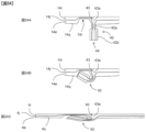
- the present perspective provides a method for manufacturing a double container, comprising a step of producing a container main body having an inner bag and an outer shell covering the inner bag, by performing biaxial stretch blow molding on a preform having an inner preform and an outer preform disposed to cover the inner preform, wherein the inner preform is formed by performing direct blow molding on a molten tubular parison, the inner preform is provided with a protruding sealing part in which a sealing part, formed by welding inner surfaces of the tubular parison to each other, protrudes from a main body part of the inner preform, and the protruding sealing part is provided with an extension prevention structure that prevents extension of the sealing part during the biaxial stretch blow molding.
- the present perspective provides a method for manufacturing a double container, comprising a step of producing a container main body having an inner bag and an outer shell covering the inner bag, by performing biaxial stretch blow molding on a preform having an inner preform and an outer preform disposed to cover the inner preform, wherein the inner preform is formed by performing direct blow molding on a molten tubular parison, a mouth part of the inner preform includes an engaging part for pulling out the inner bag from the container main body, and ratio of D2 to D1 is 0.35 or more, where D1 is largest outer diameter of the inner preform at the mouth part, D2 is an outer diameter of the inner preform at a height of 0.1H from a bottom part of the inner preform, and H is a total height of the inner preform.
- the present perspective provides a method for manufacturing a double container, comprising a step of producing a container main body having an inner bag and an outer shell covering the inner bag, by performing biaxial stretch blow molding on a preform having an inner preform and an outer preform disposed to cover the inner preform, wherein the inner preform is formed by performing direct blow molding on a molten tubular parison, the inner bag includes a thin wall part with a wall thickness of 100 ⁇ m or less, and the inner preform is provided with an uneven shape or a lubricant on an outer surface of an area that includes a part corresponding to the thin wall part.
- the present perspective provides a method for manufacturing a double container, comprising a step of producing a container main body having an inner bag and an outer shell covering the inner bag, by performing biaxial stretch blow molding on a preform having an inner preform and an outer preform disposed to cover the inner preform, wherein the inner preform is formed by performing direct blow molding on a molten tubular parison, a mouth part of the inner preform includes an engaging part for pulling out the inner bag from the container main body, ratio of D1 to D3 is 1.5 or more, where D1 is largest outer diameter of the mouth part of the inner preform, and D3 is an outer diameter of the tubular parison, and an open end of the inner preform includes an enlarged diameter structure that prevents deformation of the mouth part.
- the present perspective provides a double container, comprising a container main body and a mouth part attachment, wherein the container main body includes an inner bag and an outer shell disposed to cover the inner bag, the mouth part attachment is attached to a mouth part of the container main body by pushing-in, and the inner bag is configured to move in a direction of coming out of the container main body via rotation of the mouth part attachment with respect to the outer shell.
- the present perspective provides a double container, comprising a container main body, a mouth part attachment, and a shrink film attached in such a way to cover the container main body and the mouth part attachment
- the container main body includes an inner bag and an outer shell disposed to cover the inner bag
- the mouth part attachment includes an inner plug and an overcap
- the inner plug is engaged with a mouth part of the inner bag in a circumferential direction and an axial direction
- the overcap is engaged with the inner plug
- the inner bag is configured to move in a direction of coming out of the container main body by rotating the inner plug with respect to the outer shell
- the shrink film is installed in a covering state where the shrink film covers the container main body and the inner plug but does not cover the overcap, or the shrink film includes an easy-to-tear line such that the covering state is achieved after removing a part of the shrink film.
- the present perspective provides a method for discharging contents in a double container, comprising a pulling out step and a discharging step, wherein the double container includes a container main body and a cap attached to a mouth part of the container main body, the container main body includes an inner bag and an outer shell disposed to cover the inner bag, the contents are contained within the inner bag, the cap is engaged with the inner bag, in the pulling out step, the inner bag is pulled out from the container main body while a part of the contents remain in the inner bag and the cap is engaged with the inner bag, and in the discharging step, the contents remaining in the inner bag are discharged after being pulled out from the container main body.
- the present perspective provides a double container, comprising a container main body, wherein the container main body includes an inner bag and an outer shell disposed to cover the inner bag, the container main body has three or more corner parts spaced apart in a circumferential direction on a cross-section at a distance of 0.2J from a bottom surface of the container main body, where J is a total height of the container main body, and connecting parts having a larger radius of curvature than the corner parts are provided between the corner parts.
- the present perspective provides a double container, comprising a container main body, wherein the container main body includes an inner bag and an outer shell disposed to cover the inner bag, and the inner bag includes, in order from inside of the container main body, an inner layer, a gas barrier layer, and an outer layer.
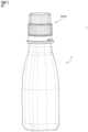
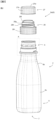
- the double container 1 includes a container main body 2 and a mouth part attachment 8.
- the container main body 2 includes a mouth part 5, a trunk part 6, and a bottom part 7.
- the mouth part 5 is a tubular (preferably cylindrical) part having an open end 5c.
- the mouth part 5 includes an engaging part 4m to which a mouth part attachment 8 such as a cap or a pump is attachable. Details of the engaging part 4m are described later.
- the mouth part 5 is provided with a flange 5b. The flange 5b can be used to support the mouth part 5 when the mouth part attachment 8 is attached to the mouth part 5.
- the trunk part 6 is disposed adjacent to the mouth part 5 on a side further away from the open end 5c than the mouth part 5.
- the trunk part 6 has a larger outer diameter (in this specification, "outer diameter” means the diameter of an equivalent circle when the cross-section is not circular) than the mouth part 5.
- the trunk part 6 has a tubular shape, and the bottom part 7 is provided at the lower end of the trunk part 6 and closes the lower end of the trunk part 6.
- the trunk part 6 includes a shoulder part 6b whose outer diameter increases as the distance from the mouth part 5 increases. Further, the trunk part 6 includes a trunk part 6c, which is disposed closer to the bottom part 7 than the shoulder part 6b.
- the trunk part 6c has, for example, a shape in which the outer diameter is substantially constant toward the bottom part 7, or a shape in which the diameter decreases toward the bottom part 7.
- the container main body 2 includes an inner bag 4 and an outer shell 3.
- the outer shell 3 is disposed in such a way to cover the inner bag 4.
- the inner bag main body 4d excluding the protrusion 4c is housed in the outer shell 3.
- parts of the inner bag 4 that correspond to the mouth part 5, trunk part 6, and bottom part 7 of the container main body 2 are referred to as the mouth part 5, trunk part 6, and bottom part 7 of the inner bag 4, respectively.
- the average wall thickness of the outer shell 3 at the center of the trunk part 6 in the height direction is, for example, 200 to 800 ⁇ m, and preferably 250 to 500 ⁇ m.
- This wall thickness is, for example, 250, 300, 350, 400, 450, 500, 550, 600, 650, 700, 750, 800 ⁇ m; the wall thickness may also be set to an arbitrary value between any two of these exemplary values.
- the average wall thickness of the inner bag 4 at the center of the trunk part 6 in the height direction is, for example, 50 to 250 ⁇ m, and preferably 50 to 100 ⁇ m.
- This wall thickness is, for example, 50, 60, 70, 80, 90, 100, 110, 120, 130, 140, 150, 160, 170, 180, 190, 200, 210, 220, 230, 240, 250 ⁇ m; the wall thickness may also be set to an arbitrary value between any two of these exemplary values, or equal to or below any of these exemplary values.
- the average wall thickness at a predetermined height position means the average value of the measurements at eight measurement locations disposed at equal intervals in the circumferential direction at the height position.
- the present invention is aimed at making it easy to pull out the inner bag 4 through the mouth part 5 of the outer shell 3, the present invention is particularly effective when the mouth part attachment 8 is not provided with a check valve.
- the inner diameter of the mouth part 5 of the outer shell 3 is, for example, 20 to 50 mm, and preferably 25 to 40 mm. This diameter is, for example, 20, 25, 30, 35, 40, 45, 50 mm; the diameter may also be set to an arbitrary value between any two of these exemplary values.
- the length of the mouth part 5 is, for example, 15 to 45 mm. This length is, for example, 15, 20, 25, 30, 35, 40, 45 mm; the length may also be set to an arbitrary value between any two of these exemplary values.
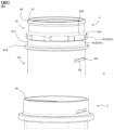
- the inner bag 4 includes a protrusion 4c that protrudes from the open end 3a of the outer shell 3.
- the protrusion 4c includes a protruding tube 4c1, an engaging part 4c2, an annular protrusion 4c5, and an abutting flange 4c4.
- the annular protrusions 4c5 engage with the mouth part attachment 8 in the axial direction.
- the engaging protrusions 4c2 engage with the mouth part attachment 8 in the circumferential direction.
- the "axial direction” is the direction in which the central axis C of the mouth part 5 extends, or in other words, the direction in which the inner bag 4 is extracted from the container main body 2.
- the "circumferential direction” is a direction in which the mouth part 5 is rotated about the central axis C, or in other words, a direction in which the inner bag 4 is rotated with respect to the outer shell 3, in the mouth part 5.
- the engaging protrusions 4c2 are provided at a plurality of locations (eight locations in this embodiment) spaced apart in the circumferential direction.
- the engaging protrusions 4c2 are arranged on the annular protrusions 4c5, and are arranged so as to protrude radially outward from the annular protrusion 4c5.
- the annular protrusions 4c5 and the engaging protrusions 4c2 are provided with tapered surfaces 4c8 and 4c3 on their upper surfaces. This makes it easy for the annular protrusions 28c (shown in FIG. 7A ) of the mouth part attachment 8 to climb over the annular protrusions 4c5 and the engaging protrusions 4c2, as described later.
- the lower surface 4c6 of the engaging protrusion 4c2 is flush with the lower surface 4c7 of the annular protrusion 4c5, or is positioned closer to the open end of the inner bag 4 than the lower surface 4c7 of the annular protrusion 4c5. According to such a configuration, the engagement between the mouth part attachment 8 and the inner bag 4 is reinforced, since the axial engagement between the annular protrusions 4c5 and the mouth part attachment 8 is reinforced by the engaging protrusion 4c2.
- the abutting flange 4c4 is positioned so as to contact the open end 3a.
- the abutting flange 4c4 is an annular part whose diameter is larger than that of the protruding tube 4c1.
- cam protrusions 4g and engaging protrusions 4h are provided on the outer peripheral surface of the inner bag main body 4d.
- the engaging protrusions 4h are provided on the cam protrusions 4g.
- the lower surfaces of the cam protrusions 4g and the engaging protrusions 4h are each inclined so as to approach the open end 5c as they proceed counterclockwise when viewed from the open end 5c side of the mouth part 5.
- the inner peripheral surface of the outer shell 3 is provided with cam rails 3l, engaging recesses 3m, and engaging protrusions 3n.
- the engaging recesses 3m are provided such that the lower surfaces of the engaging recesses 3m are continuous with the upper surfaces of the cam rails 3l.
- the upper surfaces of the cam rails 3l and the lower surfaces of the engaging recesses 3m are inclined so as to approach the open end 3a as they proceed counterclockwise when viewed from the open end 3a side.
- the engaging protrusions 3n are positioned adjacent to an engaging recess 3m.
- the engaging protrusions 4h are disposed within the engaging recesses 3m, and the lower surfaces of the cam protrusions 4g are in contact with the upper surfaces of the cam rails 3l.
- a cam mechanism 31 is constituted by the cam protrusions 4g and the cam rails 3l.
- the engaging recesses 3m are through holes, but may be non-through holes.
- An enlarged diameter structure 4k is provided at the open end 4l of the inner bag 4.
- the enlarged diameter structure 4k increases the rigidity of the opening 5 of the inner bag 4 and prevents deformation of the opening 5 of the inner bag 4.
- the inner bag 4 is extracted using the engaging part 4m (more specifically, the annular protrusions 4c5 and the engaging protrusions 4c2) provided on the inner bag 4, there are cases where a high load is applied to the inner bag 4. In such cases, it may become difficult to extract the inner bag 4 if the open end 4l of the inner bag 4 is easily deformed. In this embodiment, however, the inner bag 4 is smoothly extractable since the deformation of the open end 4l of the inner bag 4 is prevented.
- the mouth part attachment 8 is configured to be attachable to the mouth part 5 of the container main body 2 by pushing-in; by pressing the mouth part attachment 8 in the direction of the bottom part 7 while the mouth part attachment 8 is placed over the mouth part 5, the mouth part attachment 8 can be engaged with and attached to the mouth part 5. Since the push-in type mouth part attachment 8 can be attached simply by pressing, it has the advantage that the step of attaching the mouth part attachment 8 can be simplified on the line for filling the contents.
- a push-in type mouth part attachment generally includes a separation band that is separable from the inner plug, and the mouth part attachment is configured to be attached to the container main body by engaging the engaging part of the separation band with the engaging part of the outer shell.
- the engaging force between the mouth part attachment and the outer shell is weakened (usually, disengaged) by first tearing off the connection between the inner plug and the separation band and removing the separation band. After that, an operation is performed to remove the mouth part attachment from the mouth part.
- the operation of weakening the engagement force may be an operation of weakening the engagement force between the separation band and the outer shell, for example, by making a notch in the separation band without removing the separation band.
- the inner bag 4 is configured to move in the direction of coming out of the container main body 2 (i.e., to lift the inner bag 4) by rotating the mouth part attachment 8 with respect to the outer shell 3, and it is possible to rotate the mouth part attachment 8 relative to the outer shell 3 without performing an operation to weaken the engagement force between the mouth part attachment 8 and the outer shell 3 before rotating the mouth part attachment 8 relative to the container main body 2.
- the mouth part attachment 8 can be rotated while the mouth part attachment 8 and the outer shell 3 are engaged with each other when the mouth part attachment 8 is attached to the mouth part 5 of the container main body 2.
- the mouth part attachment 8 is engaged, by pushing-in, with the mouth part 5 of the inner bag 4 in the circumferential direction and the axial direction, and as the mouth part attachment 8 rotates, the inner bag 4 is configured to rotate relative to the outer shell 3.
- the cam mechanism 31 provided between the inner bag 4 and the outer shell 3, the inner bag 4 is configured to move in the direction of coming out of the container main body 2 as the inner bag 4 rotates.
- the inner bag 4 can be moved in the direction of coming out of the container main body 2 simply by rotating the mouth part attachment 8 without performing troublesome operations such as removing the separation band in advance. After that, the inner bag 4 is extractable from the container main body 2 by pulling the mouth part attachment 8. In other words, since the inner bag 4 is extractable simply by turning and pulling the mouth part attachment 8, the operation required to extract the inner bag 4 becomes very simple.
- the rotation of the mouth part attachment 8 at this time is preferably rotation in the loosening direction of right-hand threads (i.e., in the counterclockwise direction when viewed from the top of the dual container 1). In this case, there is an advantage that it is intuitively understandable that the inner bag 4 moves in the direction of coming out of the container main body 2.
- the trunk part 6 of the container main body 2 has a larger outer diameter than the mouth part 5, it is not easy to extract the inner bag 4 through the mouth part 5 of the outer shell 3 by simply pulling the inner bag 4.
- the inner bag 4 by rotating the opening 5 of the inner bag 4 and twisting the inner bag 4 to reduce the diameter of the trunk part 6 of the inner bag 4, it becomes easy for the trunk part 6 of the inner bag 4 to pass through the opening 5 of the outer shell 3, and the inner bag 4 is easily extractable from the container main body 2.
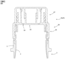
- the mouth part attachment 8 is a cap 8a, and includes an inner plug 26 and an overcap 27.
- the inner plug 26 is engaged, by pushing-in, with the opening 5 of the inner bag 4 in the circumferential direction and the axial direction.
- the overcap 27 is screwed onto the inner plug 26.
- the overcap 27 includes an outer tube 27a, an intermediate tube 27b, an inner tube 27c, and a top plate 27d.
- the inner plug 26 includes a main body part 28 and an opening part 32.
- the main body part 28 and the opening part 32 are connected to each other via an easy-to-tear connecting part 30.
- the main body part 28 includes an outer tube 28a, an inner tube 28b, an annular protrusion 28c, an engaging protrusion 28d, a top plate 28e, a discharging tube 28f, and a mounting tube 28g.
- the opening part 32 and the connecting part 30 are arranged inside the discharging tube 28f and the inner tube 28b.
- the opening part 32 is provided with an engaging tube 32a provided with an engaging part (not shown), and the inner tube 27c and the engaging tube 32a are engaged in the circumferential direction and the axial direction. According to such a configuration, by rotating the overcap 27 with respect to the main body part 28, it becomes possible to rotate the engaging tube 32a with respect to the main body part and break the connecting part 30.
- breaking the connecting part 30 By breaking the connecting part 30, the opening part 32 is separated from the main body part 28, and a flow hole is formed inside the discharging tube 28f and the inner tube 28b. The contents in the inner bag 4 can be discharged through this flow hole.
- a knurl 28i is provided on the outer peripheral surface of the outer tube 27a, making it easy to grip and rotate the inner plug 26.
- the top plate 28e is provided on the upper surface of the outer tube 28a.
- An inner tube 28b is provided on the lower surface of the top plate 28e.
- the inner tube 28b is a so-called inner ring that has a smaller diameter than the outer tube 28a and is arranged inside the outer tube 28a.
- a discharging tube 28f and a mounting tube 28g are provided on the top surface of the top plate 28e.
- the contents in the inner bag 4 are discharged through the discharging tube 28f.
- a male threaded part 28h is provided on the outer peripheral surface of the mounting tube 28g, and a female threaded part 28h is provided on the inner peripheral surface of the outer tube 27a of the overcap 27; as the male threaded part 28h engages with the female threaded part 27f, the overcap 27 is screwed onto the inner plug 26.
- the overcap 27 can be attached to and removed from the inner plug 26 by rotating the overcap 27 relative to the inner plug 26.
- the overcap 27 When the overcap 27 is attached to the inner plug 26, the intermediate tube 27b is inserted into the discharging tube 28f, and the outer peripheral surface of the intermediate tube 27b is brought into close contact with the inner peripheral surface of the discharging tube 28f. The upper side of the discharging tube 28f is closed by the overcap 27.
- the annular protrusions 28c are annular protrusions provided on the inner peripheral surface of the outer tube 28a in such a way to extend in the circumferential direction.
- the engaging protrusions 28d are provided at a plurality of locations (eight locations in this embodiment) spaced apart in the circumferential direction.
- the engaging protrusions 28d are disposed on the annular protrusions 28c so as to protrude radially inward from the annular protrusion 28c.
- the engaging protrusions 28d are arranged between the adjacent engaging protrusions 4c2, so that the main body part 28 engages with the mouth part 5 of the inner bag 4 in the circumferential direction.
- the overcap 27 is preferably screwed onto the inner plug 26 with right-hand threads.
- the overcap 27 and the inner plug 26 can be unscrewed from each other.
- the inner bag 4 is configured to move in the direction of coming out of the container main body 2.
- the overcap 27 can be removed by rotating the overcap 27 in the loosening direction of right-hand threads, and by rotating the inner plug 26 in the loosening direction of right-hand threads, the inner bag 4 can be lifted up. Since both operations are performed in the same direction of rotation, they have the advantage of being simple to operate.
- the value of T2/T1 (i.e., T2 divided by T1) is preferably equal to or greater than 1.2, where T1 is the overcap rotational torque required to rotate the overcap 27 for the first time with respect to the inner plug 26 in the loosening direction of right-hand threads, and T2 is the inner plug rotational torque required to rotate the inner plug 26 for the first time with respect to the outer shell 3 in the loosening direction of right-hand threads.
- T1 is the overcap rotational torque required to rotate the overcap 27 for the first time with respect to the inner plug 26 in the loosening direction of right-hand threads
- T2 is the inner plug rotational torque required to rotate the inner plug 26 for the first time with respect to the outer shell 3 in the loosening direction of right-hand threads.
- T2/T1 is, for example, 1.2 to 5, and preferably 1.5 to 3.
- the value of T2/T1 is, for example, 1.2, 1.5, 2.0, 2.5, 3.0, 3.5, 4.0, 4.5, 5.0; the value of T2/T1 may also be set to an arbitrary value between any two of these exemplary values.
- the value of T1 is, for example, 40 to 120 N ⁇ cm, preferably 60 to 100 N ⁇ cm.
- the value of T2 is, for example, 100 to 200 N ⁇ cm, preferably 130 to 170 N ⁇ cm.
- the value of T1 is, for example, 40, 50, 60, 70, 80, 90, 100, 110, 120 N cm, or may also be set to an arbitrary value between any two of these exemplary values, or equal to or below any of these exemplary values, or equal to or above any of these exemplary values.
- the value of T2 is, for example, 100, 110, 120, 130, 140, 150, 160, 170, 180, 190, 200 N cm, or may also be set to an arbitrary value between any two of these exemplary values, or equal to or below any of these exemplary values, or equal to or above any of these exemplary values.
- the overcap rotation torque T1 is the torque necessary to break the connecting part 30 and separate the opening part 32 from the main body part 28.
- the overcap 27 is provided with an opening ring via an easy-to-tear connecting part, and the opening ring engages the inner plug 26 in the circumferential direction. In such a configuration, the torque required to break the thin wall part and separate the opening ring from the overcap 27 is the overcap rotation torque T1.
- a rotation restriction structure that restricts rotation of the overcap 27 with respect to the inner plug 26; when the rotation restriction by the rotation restriction structure is released at a predetermined torque (e.g., when rotation is restricted as the protrusion of the overcap 27 and the protrusion of the inner plug 26 come into contact with each other, and the restriction on rotation is released as the protrusion of the overcap 27 climbs over the protrusion of the inner plug 26), the torque required to release the restriction is the overcap rotation torque T1.
- the inner plug rotational torque T2 is the torque necessary for the engaging protrusions 4h to climb over the engaging protrusions 3n.
- the inner plug 26 and the outer shell 3 may be engaged in the circumferential direction, and the engagement may be released when the inner plug rotation torque T2 is applied.
- T3/T2 is preferably equal to or greater than 1.2, where T3 is the overturn torque required to rotate the inner plug 26 for the first time in the loosening direction of right-hand threads with respect to the inner bag 4. This prevents the inner plug 26 from rotating idly relative to the inner bag 4.
- the value of T3/T2 is, for example, 1.2 to 5, and is preferably 1.5 to 3. Specifically, for example, the value of T3/T2 is 1.2, 1.5, 2.0, 2.5, 3.0, 3.5, 4.0, 4.5, 5.0, or may also be set to an arbitrary value between any two of these exemplary values, or equal to or above any of these exemplary values.
- the value of T3 is, for example, 200 N ⁇ cm or more, and is preferably 200 to 1000 N ⁇ cm. Specifically, for example, the value of T3 is 200, 250, 300, 350, 400, 500, 1000 N ⁇ cm, or may also be set to an arbitrary value between any two of these exemplary values.
- the overturn torque T3 is the torque necessary for the engaging protrusions 28d to climb over the engaging protrusions 4c2.
- a shrink film 33 is used to prevent the occurrence of such problems.
- the shrink film 33 covers the container main body 2, the inner plug 26, and the overcap 27 prior to unsealing.
- the shrink film 33 is provided with easy-to-tear lines 33a and 33b.
- the easy-to-tear lines 33a and 33b are lines such as perforations or half-cut lines that make it easy to cut the shrink film.
- the easy-to-tear line 33a is provided so as to extend in the circumferential direction of the inner plug 26 at the boundary between the inner plug 26 and the overcap 27 or at a position facing the inner plug 26.
- the shrink film 33 When a part of the shrink film 33 (i.e., the upper part 33c above the easy-to-tear line 33a) is removed along the easy-to-tear line 33a, the shrink film 33 still covers the inner plug 26 but no longer covers the overcap 27. In this state, it is difficult to grasp and rotate the inner plug 26, so that erroneous operations such as accidentally rotating the inner plug 26 is preventable.
- the shrink film 33 instead of providing the easy-to-tear line 33a, the shrink film 33 may be attached in such a way that the upper edge of the shrink film 33 is located at the boundary between the inner plug 26 and the overcap 27 or at a position facing the inner plug 26. In this case, a covering state is achieved in which the inner plug 26 is covered but the overcap 27 is not covered, before a part of the shrink film 33 is removed.
- the easy-to-tear line 33b is provided to facilitate the removal of the lower part 33d of the shrink film 33 below the easy-to-tear line 33a. It is preferable that the easy-to-tear line 33b is provided non-parallel to the easy-to-tear line 33a or perpendicular to the easy-to-tear line 33a. Moreover, it is preferable that the easy-to-tear line 33b is connected to the easy-to-tear line 33a, and preferably reaches the lower edge of the lower part 33d.
- the prevention of erroneous operations using a shrink film is also applicable to the cases where the cap 8a is not of a push-in type. If the cap 8a is of a screw type, the cap 8a is attached to the container main body 2 by screwing the cap 8a onto the opening of the outer shell 3.
- the prevention of erroneous operations using a shrink film is also applicable to the cases where the overcap is engaged with the inner plug 26 by, for example, snap engagement rather than screw engagement.
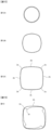
- the shape of the body 6 of the container main body 2 becomes approximately square in cross-section (square with rounded corners) as the cross-section approaches the bottom part 7. More specifically, the cross-section is circular at the upper end of the shoulder part 6b as shown in FIG. 12A , approximately square at the trunk part main body 6c as shown in FIG. 12C , and a shape between a circle and an approximate square in the middle of the shoulder part 6b as shown in FIG. 12B . In other words, in the shoulder part 6b, the cross-section of the container main body 2 is expanded toward the bottom part 7, and the shape of the cross-section gradually approaches an approximate square. Further, the bottom part 7 is provided with a recess 7a.
- FIG. 12C shows a cross-section P at a distance of 0.2J from the bottom surface of the container main body 2, where J is the total height of the container main body 2.
- the container main body 2 has three or more corner parts 2a that are separated among one another in the circumferential direction, and connecting parts 2b having a larger radius of curvature than that of the corner parts 2a are provided between the corner parts 2a.
- the inner bag 4 also has a shape similar to that of the container main body 2. Unless otherwise mentioned, the radius of curvature means the value at the outer surface of the container main body 2.
- the connecting part 2b is more easily rotated than the corner part 2a when the inner bag 4 is rotated counterclockwise with respect to the outer shell 3.
- a bent shape 2c is likely to be formed near the boundary between the connecting part 2b and the corner part 2a. If the inner bag 4 is further rotated counterclockwise in this state, the diameter of the inner bag 4 is reduced in such a way that the corner parts 2a of the inner bag 4 are folded, making it easier to pull out the inner bag 4.
- the number of corner parts 2a is four, but the same effects can be achieved even when the number of corner parts 2a is three, or five or more.
- the number of corner parts 2a is, for example, 3 to 12, preferably 3 to 6.
- the value of (L1-L2)/L1 is preferably 0.1 or less, where L1 is the length of the longest among the connecting parts 2b, and L2 is the length of the shortest among the connecting parts 2b.
- L1 is the length of the longest among the connecting parts 2b
- L2 is the length of the shortest among the connecting parts 2b.
- the lengths of all the connecting parts 2b are approximately the same, and the cross-section is an approximate regular polygonal.
- the corner parts 2a of the inner bag 4 are more easily folded since the connecting parts 2b are more easily rotated.
- the value of R2/R1 is preferably three or more, where R1 is the minimum radius of curvature at the corner parts 2a, and R2 is the maximum radius of curvature at the connecting parts 2b.
- R1 is the minimum radius of curvature at the corner parts 2a
- R2 is the maximum radius of curvature at the connecting parts 2b.
- the connecting parts 2b may be flat surfaces, in which case the radius of curvature becomes infinite. It is preferable that the corner parts 2a are convex toward the outside of the container main body 2.
- the connecting parts 2b may be outwardly convex, flat, or inwardly convex.
- R2/R1 is, for example, 3 to 1000, specifically, for example, 3, 4, 5, 6, 7, 8, 9, 10, 11, 12, 13, 14, 15, 16, 17, 18, 19, 20, 100, 500, and 1000, or may also be set to an arbitrary value between any two of these exemplary values, or equal to or above any of these exemplary values.
- the radius of curvature R1 is, for example, 5 to 20 mm, specifically, for example, 5, 6, 7, 8, 9, 10, 11, 12, 13, 14, 15, 16, 17, 18, 19, 20 mm, or may also be set to an arbitrary value between any two of these exemplary values.
- the radius of curvature R2 is, for example, 30 mm or more, preferably 30 to 200 mm, and specifically, for example, 30, 40, 50, 60, 70, 80, 90, 100, 110, 120, 130, 140, 150, 160, 170, 180, 190, 200 mm, or may also be set to an arbitrary value between any two of these exemplary values, or equal to or above any of these exemplary values.
- R1/R3 is, for example, 0.2 to 0.6, and specifically, for example, 0.20, 0.25, 0.30, 0.35, 0.40, 0.45, 0.50, 0.55, 0.60, or may also be set to an arbitrary value between any two of these exemplary values, where R3 is the radius of an equivalent circle of the container main body 2 at the cross-section P.
- the radius R3 of an equivalent circle is, for example, 15 to 40 mm, specifically, for example, 15, 16, 17, 18, 19, 20, 21, 22, 23, 24, 25, 26, 27, 28, 29, 30, 31, 32, 33, 34, 35, 36, 37, 38, 39, 40 mm, or may also be set to an arbitrary value between any two of these exemplary values.
- the value of T1/T2 is preferably 0.90 or less, where T1 is the minimum wall thickness of the inner bag 4 at the corner parts 2a, and T2 is the maximum wall thickness of the inner bag 4 at the connecting parts 2b.
- the value of T1a/T2a is preferably 0.90 or less, where T1a is the average value of the wall thickness of the inner bag 4 at all corner parts 2a, and T2a is the average value of the wall thickness of the inner bag 4 at all connecting parts 2b. In this case, the corner parts 2a of the inner bag 4 are more easily folded.
- T1/T2 and T1a/T2a are each, for example, 0.40 to 0.90, and specifically, for example, 0.40, 0.45, 0.50, 0.55, 0.60, 0 .65, 0.70, 0.75, 0.80, 0.85, 0.90, or may also be set to an arbitrary value between any two of these exemplary values.
- the values of T1 and T1a are each preferably 95 ⁇ m or less.
- the values of T1 and T1a are each, for example, 50 to 95 ⁇ m, specifically, for example, 50, 55, 60, 65, 70, 75, 80, 85, 90, 95 ⁇ m, or may also be set to an arbitrary value between any two of these exemplary values, or equal to or below any of these exemplary values.
- T2 and T2a are each, for example, 60 to 150 ⁇ m, specifically, for example, 60, 70, 80, 90, 100, 110, 120, 130, 140, 150 ⁇ m, or may also be set to an arbitrary value between any two of these exemplary values.
- the inner bag 4 is able to be pulled out from the container main body 2 using the mouth part attachment 8. As shown in FIG. 14 , the mouth part attachment 8 remains engaged with the inner bag 4 after being pulled out.
- the inner bag 4 is pulled out from the container main body 2 with some of the contents remaining in the inner bag 4 (pullout step), and then the contents remaining in the inner bag 4 can be discharged (discharge step).
- the inner bag 4 Since the inner bag 4 has higher flexibility than the outer shell 3, squeezing or compressing the inner bag 4 allows the contents to be easily discharged, and the amount of contents remaining when further discharge becomes impossible (hereinafter referred to as "final residual amount”) is reducible.
- the final residual amount tends to increase as the viscosity increases, but according to the method of this embodiment, it is possible to prevent an increase in the final residual amount even when the viscosity is high. Therefore, the method of this embodiment has significant technical significance when the contents have a high viscosity (for example, 100 mPa ⁇ sec or more).
- the viscosity of the contents is, for example, 100 to 10,000 mPa ⁇ sec, and specifically, for example, 100, 200, 300, 400, 500, 600, 700, 800, 900, 1,000, 2,000, 3,000, 4,000, 5,000, 6,000, 7,000, 8,000, 9,000, and 10,000 mPa ⁇ sec, or may also be set to an arbitrary value between any two of these exemplary values, or equal to or above any of these exemplary values.
- the bottom part 7 of the container main body 2 is provided with a truncated conical recess 7a.
- the recess 7a is also provided in the bottom part 7 of the inner bag 4. Since the truncated conical recess 7a has a circular cross-section (i.e, cross-section perpendicular to the central axis C), it is difficult to be deformed. As a result, if the truncated conical recess 7a exists in the inner bag 4, there is a risk that sufficient reduction in the final residual amount is not achievable. From this point of view, it is preferable to provide the bottom part of the container main body 2 with a recess having an oval-shape cross-section. Since such a recess is easier to deform than a recess with a circular cross-section, the final residual amount is further reducible.
- the axial engagement between the annular protrusions 4c5 and the mouth part attachment 8 is reinforced by the engaging protrusions 4c2, which makes the engagement between the cap 8a and the inner bag 4 strong and prevents the cap 8a from coming off from the inner bag 4.
- the inner bag 4 has a small wall thickness. This is because the smaller the wall thickness of the inner bag 4 is, the more flexible the inner bag 4 becomes, making it easier to reduce the final residual amount, and the amount of resin used becomes reducible.
- the inner bag 4 includes a thin wall part having a wall thickness of 100 ⁇ m or less. Further, it is preferable that the thin wall part be provided at a position closer to the bottom part than the center of the trunk part 6 in the height direction.
- the wall thickness of the thin wall part is preferably 95 ⁇ m or less, more preferably 90 ⁇ m or less.
- the wall thickness of the thin wall part is, for example, 50 to 100 ⁇ m, specifically, for example, 50, 55, 60, 65, 70, 75, 80, 85, 90, 95, 100 ⁇ m, or may also be set to an arbitrary value between any two of these exemplary values.
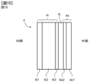
- the inner bag 4 may have a single layer structure or a multilayer structure. As shown in FIG. 15 , the inner bag 4 preferably includes, in order from the inside of the inner bag 4, an inner layer 4i, a gas barrier layer 4j, and an outer layer 4e.
- the inner layer 4i is a layer disposed nearer to the inside of the inner bag 4 than the gas barrier layer 4j.
- the wall thickness of the inner layer 4i is, for example, 5 to 60 ⁇ m, specifically, for example, 5, 10, 15, 20, 25, 30, 35, 40, 45, 50, 55, 60 ⁇ m, or may also be set to an arbitrary value between any two of these exemplary values.
- the inner layer 4i preferably includes, in order from the inside of the inner bag 4, an innermost layer 4i1, a repro layer 4i2, and an adhesive layer 4i3.
- the innermost layer 4i1 is preferably made of a resin with excellent moisture barrier properties such as polyolefin (e.g., polyethylene, polypropylene) or PET.
- the innermost layer 4i1 is a layer that comes into contact with the contents in the inner bag 4, and is preferably made of new resin (hereinafter referred to as "virgin resin") rather than recycled resin in order to prevent contamination of the contents.
- the repro layer 4i2 is preferably composed of a resin containing recycled resin, and is preferably composed of a mixed resin composed of recycled resin and virgin resin. By providing the repro layer 4i2, environmental load and container manufacturing costs can be reduced. The repro layer 4i2 is omittable if unnecessary.
- the mixed resin preferably contains 15 to 50% by mass of recycled resin (15, 20, 25, 30, 35, 40, 45, 50% by mass) and 50 to 85% by mass of virgin resin. (50, 55, 60, 65, 70, 75, 80, 85% by mass).
- the proportion of recycled resin and virgin resin may also be set to an arbitrary value between any two of these exemplary values in parentheses.
- the recycled resin is a resin obtained by recycling scraps generated during molding of the container main body 2. Since the scrap includes all the layers of the container main body 2, the recycled resin is a mixture of resin compositions constituting each of all the layers of the container main body 2.
- the adhesive layer 4i3 is made of adhesive resin.
- adhesive resins include acid-modified polyolefin resins (e.g., maleic anhydride-modified polyethylene, maleic anhydride-modified polypropylene), and the like.
- the outer layer 4e is a layer disposed nearer to the outside of the inner bag 4 than the gas barrier layer 4j.
- the wall thickness of the outer layer 4e is, for example, 5 to 60 ⁇ m, specifically, for example, 5, 10, 15, 20, 25, 30, 35, 40, 45, 50, 55, 60 ⁇ m, or may also be set to an arbitrary value between any two of these exemplary values.
- the outer layer 4e preferably includes, in order from the outside of the inner bag 4, an outermost layer 4e1 and an adhesive layer 4e2.
- the outermost layer 4e1 is preferably made of a resin with excellent moisture barrier properties such as polyolefin (e.g., polyethylene, polypropylene) or PET.
- the outermost layer 4e1 is a layer exposed to the outside of the inner bag 4, and is preferably made of virgin resin in order to prevent contamination of the external environment.
- the description of the adhesive layer 4e2 is the same as that of the adhesive layer 4i3.
- the value of the wall thickness of inner layer 4i divided by the wall thickness of outer layer 4e is , for example, preferably 0.2 to 5. Specifically, this value is, for example, 0.2, 0.3, 0.4, 0.5, 0.6, 0.7, 0.8, 0.9, 1.0, 1.1, 1.2, 1.3, 1.4, 1.5, 1.6, 1.7, 1.8, 1.9, 2.0, 2.1, 2.2, 2.3, 2.4, 2.5, 2.6, 2.7, 2.8, 2.9, 3.0, 3.5, 4.0, 4.5, 5.0, or may also be set to an arbitrary value between any two of these exemplary values.
- the gas barrier layer 4j is more reliably protectable from moisture in the contents. If the outer layer 4e is thicker than the inner layer 4i, the gas barrier layer 4j is more reliably protectable from external moisture.
- the repro layer 4i2 may be disposed in both the inner layer 4i and the outer layer 4e, or may be disposed only in the outer layer 4e.
- the repro layer 4i2 may include a material, such as a post-consumer material, that may contain a component and/or a strong odor that is likely to migrate to the contents.
- the repro layer 4i2 is preferably disposed in the outer layer 4e. In this case, the amount of resin used in the repro layer 4i2 may be increased by making the outer layer 4e thicker than the inner layer 4i.
- the gas barrier layer 4j is made of gas barrier resin.
- the gas barrier resin is a resin whose oxygen permeability is less than 50 cc/(m 2 *24 hours*atm) in an environment of 20°C and 65% RH when formed into a 20 ⁇ m thick film.
- the oxygen permeability is, for example, 0 to 49 cc/(m 2 *24 hours*atm), and specifically, for example, 0.01, 0.1, 0.2, 0.5, 1, 2, 5, 10, 15, 2 0, 25, 30, 35, 40, 45, 49 cc/(m 2 *24 hours*atm), or may also be set to an arbitrary value between any two of these exemplary values, or equal to or below any of these exemplary values.
- the ratio of oxygen permeability in an environment of 20°C and 100% RH to oxygen permeability in an environment of 20°C and 40% RH, of the gas barrier resin is preferably 2 or more; equal to or above 5 is more preferable.
- This value is, for example, 2 to 10,000, specifically, for example, 2, 5, 10, 20, 50, 100, 200, 1,000, 10,000, or may also be set to an arbitrary value between any two of these exemplary values, or equal to or above any of these exemplary values.
- the gas barrier resin may be composed only of a resin with high gas barrier properties such as EVOH or polyamide, or may be a mixed resin of the above resins and another resin.
- the another resin can be adhesive resin.
- the wall thickness of the gas barrier layer 4j is, for example, 20 to 100 ⁇ m, specifically, for example, 20, 30, 40, 50, 60, 70, 80, 90, 100 ⁇ m, or may also be set to an arbitrary value between any two of these exemplary values.
- the container main body 2 can be formed by heating a preform 15 and performing biaxial stretch blow molding.
- the preform 15 can be constructed by covering an inner preform 14, which will become the inner bag 4, with an outer preform 13, which will become the outer shell 3.
- the inner preform 14 has a bottomed tubular shape and includes a mouth part 14a, a trunk part 14b, and a bottom part 14c.
- a protrusion 14d is provided at the open end of the mouth part 14a.
- the protrusion 14d does not deform during molding and becomes the protrusion 4c in its original shape. Hence, the descriptions of the protrusion 4c also apply to the protrusion 14d.
- the protrusion 14d is provided with an engaging part 14m.
- the engaging part 14m becomes the engaging part 4m after molding and is used for pulling out the inner bag 4.
- the bottom part 14c is provided to close the lower end of the trunk part 14b.
- a positioning pin (not shown) may be provided on the bottom part 14c.
- the outer preform 13 has a bottomed tubular shape and includes a mouth part 13a, a trunk part 13b, and a bottom part 13c.
- the bottom part 13c is provided to close the lower end of the trunk part 13b.
- the bottom part 13c is provided with an annular protrusion 13d and a positioning hole (not shown).
- the preform 15 can be formed by covering the inner preform 14 with the outer preform 13. If the inner preform 14 is provided with a positioning pin, this positioning pin can be inserted into the positioning hole of the outer preform 13 to position the inner preform 14 and the outer preform 13 relative to each other.
- the opening 14a and the opening 13a face each other, and the trunk part 14b and the trunk part 13b face each other.
- the mouth parts 13a and 14a become the mouth part 15a of the preform 15
- the trunk parts 13b and 14b become the trunk part 15b of the preform 15
- the bottom parts 13c and 14c become the bottom part 15c of the preform 15.
- the trunk part 15b and bottom part 15c are mainly stretched in biaxial stretch blow molding.
- the inner preform 14 and the outer preform 13 can be formed by direct blow molding, injection molding, or the like of a thermoplastic resin such as polyester (e.g., PET) or polyolefin (e.g., polypropylene, polyethylene).
- a thermoplastic resin such as polyester (e.g., PET) or polyolefin (e.g., polypropylene, polyethylene).
- the inner preform 14 is made of polyolefin (e.g., polypropylene) and the outer preform 13 is made of PET.
- the polyolefin used for the inner preform 14 is preferably polypropylene rather than polyethylene. This is because the temperature at which polypropylene is suitable for biaxial stretch blow molding is closer to that of PET than polyethylene.
- the inner preform 14 is a direct blow molded body formed by direct blow molding using a molten tubular parison. In direct blow molding, it is easier to make the inner bag 4 thinner than in injection molding, so by forming the inner preform 14 by direct blow molding, it is possible to make the inner bag 4 thinner. Further, in order to form the inner bag 4 having a multilayer structure, the inner preform 14 preferably includes, in order from the inside, an inner layer 14i, a gas barrier layer 14j, and an outer layer 14e, as shown in FIG. 23 .
- the inner preform 14 it is not easy to form the inner preform 14 with such a structure by multilayer injection molding, and if a gate is provided on the bottom part 14c of the inner preform 14, for example, the resin constituting the gas barrier layer 14j may not reach the open end of the inner preform 1, potentially causing the deterioration of the gas barrier capabilities.
- direct blow molding molding is performed using a tubular parison having structures corresponding to the inner layer 14i, the gas barrier layer 14j, and the outer layer 14e, making it easy to provide the gas barrier layer 14j over the entire inner preform 14.
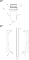
- a molten tubular parison 34 is placed between split molds 35 and 36 in an open state as shown in FIG. 19 . Then, the split molds 35 and 36 are closed as shown in FIG. 20 to turn the tubular parison 34 into a bag-shaped parison. Then, air is blown into the bag-shaped parison to form it into a shape along the shaping surfaces of the split molds 35 and 36.
- a molded body 38 with burrs 39 is formed by direct blow molding. Thereafter, the molded body 38 is taken out from the split molds 35 and 36, and the burrs 39 are removed, thereby obtaining the molded body 38 shown in FIG. 21 .
- the molded body 38 has a shape in which a bag part 40 is connected to the open end 14o of the inner preform 14.
- An annular recess 41 is provided at the boundary between the inner preform 14 and the bag part 40 to indicate a cutting site.
- the molded body 38 is cut along the annular recess 41 and the bag part 40 is removed to obtain the inner preform 14.
- the annular recess 41 is a recess on the outside of the molded body 38, but becomes an annular protrusion 41a on the inside of the molded body 38.
- the annular protrusion 41a remains partially.
- a burr 14p may protrude toward the inside of the inner preform 14, or a burr 14p may be formed during cutting even if the annular protrusion 41a is not formed inside the molded body 38.
- the burr 14p is formed in the enlarged diameter structure 14l, so the burr 14p does not impede the above-mentioned close contact.
- the value of D1/D3 is preferably 1.5 or more, where D1 is the outer diameter of the part, of the inner preform 14, having the largest outer diameter at the mouth part 14a (the outer diameter at the abutting flange 14n) as shown in FIG. 17B , and D3 is the outer diameter of the tubular parison 34 as shown in FIG. 19 .
- D1/D3 becomes larger, the blow ratio when forming the inner preform 14 becomes larger, so the wall thickness of the mouth part 14a of the inner preform 14 tends to become smaller. If the wall thickness of the mouth part 14a of the inner preform 14 is small, the rigidity of the mouth part 14a becomes small.
- the mouth part 14a can be deformed, potentially making it difficult to perform cutting accurately.
- the open end 14o of the inner preform 14 is provided with the enlarged diameter structure 14l that prevents the deformation of the opening 14a, so that the deformation of the opening 14a is prevented.
- the value of D1/D3 is preferably 2 or more, and more preferably 2.5 or more.
- the value of D1/D3 is, for example, 1.5 to 4.0, specifically, for example, 1.5, 1.6, 1.7, 1.8, 1.9, 2.0, 2.1 , 2.2, 2.3, 2.4, 2.5, 2.6, 2.7, 2.8, 2.9, 3.0, 3.1, 3.2, 3.3, 3.4, 3.5, 3.6, 3.7, 3.8, 3.9, 4. 0, or may also be set to an arbitrary value between any two of these exemplary values.
- the value of D1 is, for example, 25 to 40 mm, specifically, for example, 25, 26, 27, 28, 29, 30, 31, 32, 33, 34, 35, 36, 37, 38, 39, 40 mm, or may also be set to an arbitrary value between any two of these exemplary values.
- the value of D3 is, for example, 8 to 25 mm, specifically, for example, 8, 9, 10, 11, 12, 13, 14, 15, 16, 17, 18, 19, 20, 21, 22, 23, 24 , 25 mm, or may also be set to an arbitrary value between any two of these exemplary values.
- the inner preform 14 preferably has a wall thickness of 1.5 mm or less at the open end 14o.
- the technical significance of providing the enlarged diameter structures 14l and 4k is significant, since the rigidity of the opening 14a of the inner preform 14 and the opening 5 of the inner bag 4 is particularly low.
- This wall thickness is, for example, 0.5 to 1.5 mm, specifically, for example, 0.5, 0.6, 0.7, 0.8, 0.9, 1.0, 1.1, 1.2, 1.3, 1.4, 1.5 mm, or may also be set to an arbitrary value between any two of these exemplary values.
- the value of D2/D1 is preferably 0.35 or more, and more preferably 0.50 or more, where D2 is the outer diameter of the inner preform 14 at a height position where the height from the bottom part 14c of the inner preform 14 is 0.1H, and H is the total height of the inner preform 14 as shown in FIG. 17B .
- the value of D2 is, for example, 12 to 30 mm, specifically, for example, 12, 13, 14, 15, 16, 17, 18, 19, 20, 21, 22, 23, 24, 25, 26, 27, 28 , 29, and 30 mm, or may also be set to an arbitrary value between any two of these exemplary values.
- the value of D2/D1 is preferably 0.8 or less. If the value of D2/D1 is too large, the wall thickness of the trunk part 6 of the inner bag 4 tends to increase, and the ability to discharge the contents may deteriorate.
- D2/D1 is, for example, 0.35 to 1.0, specifically, for example, 0.35, 0.40, 0.45, 0.50, 0.55, 0.60, 0.65, 0.70, 0.75, 0.80, 0.85, 0.90, 0.95, 1.00, or may also be set to an arbitrary value between any two of these exemplary values.
- the value of D2/D3 is preferably 1.1 or more, and more preferably, 1.4 or more. In this case, a sealing part is less likely to be formed on the trunk part 14b of the inner preform 14, and the aesthetic appearance of the inner preform 14 is improved.
- the value of D2/D3 is, for example, 1.1 to 2.0, specifically, for example, 1.1, 1.2, 1.3, 1.4, 1.5, 1.6, 1.7, 1.8, 1.9, and 2.0, or may also be set to an arbitrary value between any two of these exemplary values.
- the sealing part 43 is made to protrude from the main body part 14q of the inner preform 14 to form a protruding sealing part 42, as shown in FIG. 23A .
- the protruding sealing part 42 is formed by welding the inner surfaces of a tubular parison 34 together, and protrudes from the main body part 14q of the inner preform 14.
- the main body part 14q refers to a part of the inner preform 14 other than the protruding sealing part 42.
- protruding the sealing part 43 to form the protruding sealing part 42 increases the area of the sealing surface 43a, which increases the sealing strength of the sealing part 43.
- the inner preform 14 includes an inner layer 14i, a gas barrier layer 14j, and an outer layer 14e in order from the inside as shown in FIG. 23A
- the opposing inner layers 14i are welded to each other at the sealing surface 43a.
- the gas barrier layers 14j are not welded to each other, and also the outer layers 14e are not welded to each other.
- a non-barrier area 44 in which the gas barrier layer 14j is not provided, is provided. The wider the non-barrier area 44 is, the lower the gas barrier capabilities against the contents becomes.
- the protruding sealing part 42 as shown in FIG. 24A is formed by direct blow molding, and then the protruding sealing part 42 is bent as shown in FIG. 24B to form a bent structure.
- the protruding sealing part 42 can be bent, for example, after being reheated and softened.
- the bent protruding sealing part 42 serves as an extension prevention structure that prevents the sealing part 43 from being stretched during biaxial stretch blow molding.
- the main body part 14q is provided with a groove 14r along the protruding sealing part 42.
- the amount of protrusion of the protruding sealing part 42 from the main body part 14q is reduced, and the part corresponding to the protruding sealing part 42 becomes less noticeable even after biaxial stretch blow molding.
- the protruding sealing part 42 includes a base part 42a and an outer part 42b in order from the main body part 14q side, and that the outer part 42b includes a part having a larger wall thickness than the base part 42a. According to such a configuration, it is easy to bend the protruding sealing part 42 at the base part 42a. Further, the protruding sealing part 42 is preferably provided in such a way to span the bottom part 14c and the trunk part 14b of the main body part 14q, as shown in FIGs. 17C to 17D .
- the outer part 42b includes a thick wall part 42b1 and a thin wall part 42b2 having a smaller wall thickness than the thick wall part 42b1, and the thin wall part 42b2 is provided at a position adjacent to the boundary between the bottom part 14c and the trunk part 14b. If the thick wall part 42b1 is provided at the boundary between the bottom part 14c and the trunk part 14b, trying to bend the protruding sealing part 42 results in the thick wall parts 42b1 interfering with each other, making it difficult to bend the protruding sealing part 42.
- the protruding sealing part 42 becomes easily bendable even when the protruding sealing part 42 is provided across the bottom part 14c and the trunk part 14b. It is preferable that the thick wall part 42b1 has a larger wall thickness than the base part 42a, and that the thin wall part 42b2 has a smaller wall thickness than the base part 42a.
- the inner preform 14 thinner by forming it by direct blow molding than by injection molding.
- the inner bag 4 may include a thin wall part having a wall thickness of 100 ⁇ m or less.
- the adhesion between the inner bag 4 and the outer shell 3 tends to become stronger as the inner bag 4 becomes thinner.
- the shrinkage rate of the inner bag 4 may be larger than the shrinkage rate of the outer shell 3 in the cooling step after biaxial stretch blow molding.
- the inner bag 4 does not shrink uniformly, but selectively shrinks in parts of the inner bag 4 where the adhesion to the outer shell 3 is relatively weak. As a result, wrinkles may be formed in the inner bag 4 and the appearance may become poor.
- the inner preform 14 is provided with an uneven shape, or has a lubricant, on the outer surface of the region that includes a part corresponding to the thin wall part. Both the uneven shape and the lubricant reduce the adhesion between the inner bag 4 and the outer shell 3, and hence, the inner bag 4 contracts uniformly and wrinkles are prevented.
- Methods for forming the uneven shape include post-processing the inner preform 14 to form the uneven shape, reflecting the uneven shape, which is formed on the shaping surface of split molds, on the inner preform 14, and mixing particles into the resin constituting the inner preform 14 and reflecting the shape of the particles on the surface of the inner preform 14 to form an uneven shape.
- Examples of methods for forming the uneven shape by post-processing include rubbing the surface of the inner preform 14 with a sandpaper, and sandblasting the inner preform 14.
- Examples of methods for forming an uneven shape on the shaped surface include rubbing the shaped surface with a sandpaper, and sandblasting the shaped surface.
- Examples of the particles to be mixed with the resin include inorganic particles (e.g., synthetic silicates such as talc and synthetic zeolites).
- the particle size is, for example, 1 to 50 ⁇ m, and the particle proportion is, for example, 0.5 to 10% by mass, preferably 1 to 5% by mass. Since the adhesion between the inner bag 4 and the outer shell 3 is significantly reduced when the uneven shape is formed by post-processing, this method is preferable.
- the lubricant may be applied to the outer surface of the inner preform 14, or the lubricant may be mixed with the resin constituting the inner preform 14 so that it is present on the outer surface of the inner preform 14 through bleed-out.
- the uneven shape has a random shape. Further, it is preferable that the uneven shape has an arithmetic mean roughness Ra of 1 to 200 ⁇ m. In this case, the adhesion between the inner bag 4 and the outer shell 3 is particularly effectively reducible.
- the value of Ra is specifically, for example, 1, 2, 3, 4, 5, 6, 7, 8, 9, 10, 11, 12, 13, 14, 15, 16, 17, 18, 19, 20, 30 , 40, 50, 60, 70, 80, 90, 100, 150, 200 ⁇ m, or may also be set to an arbitrary value between any two of these exemplary values.
- Arithmetic mean roughness Ra is measurable in accordance with JIS B 0601:2013.
- the protruding sealing part 42 that is not bent is formed by direct blow molding, and the protruding sealing part 42 is bent by post-processing to form a bent structure.
- a bent structure is formed in the protruding sealing part 42 during the direct blow molding of the inner preform 14. Even with such a configuration, the same effect as in the first embodiment prevents the sealing part 43 from being stretched during biaxial stretch blow molding.
- the post-processing can be omitted.
- the extension prevention structure is formed by remelting the protruding sealing part 42 after direct blow molding of the inner preform 14 and reducing its surface area. By remelting, the protruding sealing part 42 becomes bulky and its rigidity increases, and hence, it functions as an extension prevention structure.
- the aspect ratio which is defined as the height of protruding sealing part 42 divided by the wall thickness of protruding sealing part 42, is 3 or more, and the aspect ratio is reduced by remelting.
- the protruding sealing part 42 is formed in the form of a thin film, and the thin film-shaped protruding sealing part 42 is remelted into a lump.
- the wall thickness of the protruding sealing part 42 is, for example, 0.1 to 0.5 mm, preferably 0.1 to 0.3 mm, and specifically, for example, 0.1, 0.2, 0.3, 0.4, 0.5 mm, or may also be set to an arbitrary value between any two of these exemplary values.
- the height of the protruding sealing part 42 is, for example, 1.0 to 4.0 mm, preferably 1.0 to 3.0 mm, and specifically, for example, 1.0, 1.5, 2.0, 2..5, 3.0, 3.5, 4.0 mm, or may also be set to an arbitrary value between any two of these exemplary values.
- the value of the aspect ratio before remelting, and the value of the aspect ratio before remelting minus the aspect ratio after remelting are each, for example, 3 to 20, and specifically, for example, 3, 4, 5, 6, 7, 8, 9, 10, 11, 12, 13, 14, 15, 16, 17, 18, 19, 20, or may also be set to an arbitrary value between any two of these exemplary values.
- the main body part 14q is provided with a groove 14r along the protruding sealing part 42.
- the molten resin produced by remelting can be accommodated in the groove 14r.
- a bent structure is formed by bending the protruding sealing part 42 in post-processing.
- This embodiment functions as an extension prevention structure through the same effect as in the first embodiment, except that there is no groove 14r.
- a bent structure is formed by bending the protruding sealing part 42 in post-processing.
- This embodiment functions as an extension prevention structure through the same effect as in the first embodiment.
- this embodiment is the same as the first embodiment except that the mouth part 14a of the inner preform 14 is longer than that of the first embodiment, and that the shape of the protruding sealing part 42 is that of the second embodiment.
- the double container 1 can be manufactured in the same manner as in the first embodiment.
- the protruding sealing part 42 may have the configuration of that of the first or third to fifth embodiments.
- this embodiment is the same as the first embodiment, except that: a cam mechanism 31 is constituted by a cam protrusion 14s provided on the inner preform 14 and a cam rail 13e provided on the outer preform 13, and the inner bag 4 moves in the direction of coming out from the container main body 2 by rotation in the loosening direction of left-hand threads; the outer preform 13 is provided with an engaging protrusion 13f; and the shape of the protruding sealing part 42 is that of the second embodiment.
- the double container 1 can be manufactured in the same manner as in the first embodiment using the mouth part attachment 8 that is compatible with the inner preform 14 and outer preform 13 of this embodiment.
- the mouth part attachment 8 may be configured to firmly engage with the engaging protrusion 13f in the circumferential direction and become unrotatable relative to the outer shell 3.
- the mouth part attachment 8 may also be configured to engage with the engaging protrusion 13f in the circumferential direction to such an extent that it can rotate when the inner plug rotation torque T2, which is described in the first embodiment, is applied.
- a separation band that engages with the engaging protrusion 13f is provided on the mouth part attachment 8, and the mouth part attachment 8 can be removed by separating the separation band.
- the mouth part attachment 8 can be removed by applying a torque equal to or higher than the inner plug rotation torque T2 to the mouth part attachment 8, without an operation such as separating the separation band.
- the protruding sealing part 42 may have the configuration of that of the first or third to fifth embodiments.
- the preform 15 preferably includes a direct blow molded body formed by direct blow molding with a molten tubular parison.
- the preform 15 was formed by covering the inner preform 14 made of a direct blow molded body with the outer preform, but the direct blow molded body itself may be used as the preform 15.
- the preform 15 is composed of a direct blow molded body (i.e., composed only of a direct blow molded body).
- the descriptions regarding the inner preform 14 also apply to a preform composed of a direct blow molded body, unless doing so contradicts the scope of the descriptions.
- the descriptions regarding the container main body 2 also apply to a container main body manufactured by biaxially stretch blow molding a preform composed of a direct blow molded body, unless doing so contradicts the scope of the descriptions.
- Containers obtained in this embodiment include single-layer containers, multilayer containers, and laminated peelable containers.
- a multilayer container is composed of a plurality of layers (two or more layers) that cannot be separated from each other.
- the plurality of layers includes a gas barrier layer.
- a laminated peelable container is composed of an outer layer and an inner layer that are peelable from each other.
- the outer layer and the inner layer may each be a single layer or a multilayer.
- the outer layer and the inner layer can be made peelable from each other by, for example, making the innermost layer of the outer layer a polyolefin layer and the outermost layer of the inner layer an EVOH layer.
- the strength of the sealing part formed by welding the inner surfaces of the tubular parison 34 together may be insufficient.
- the main body part refers to the parts of the direct blow molded body excluding the protruding sealing part.
- a container main body 2 (capacity 200 mL) having the shape shown in FIG. 2 (however, the mouth part 5 had the shape shown in FIG. 31 ) was manufactured as Sample 1.
- Sample 1 was manufactured by forming a preform 15 in which an outer preform 13 shown in FIG. 31 is placed over an inner preform 14 having a protruding sealing part 42 that is not provided with an extension prevention structure as shown in FIG. 31 , and then by heating the preform 15 to 110°C, which is the temperature at the center of preform 15 in the height direction, and performing biaxially stretch blow molding.
- the inner preform 14 was manufactured by direct blow molding.
- the layer structure of the inner preform 14 was, in order from the inside, inner layer (i.e., polypropylene, adhesive resin), gas barrier layer (i.e., EVOH), and outer layer (i.e., adhesive resin, polypropylene, (polypropylene containing 5 mass% talc)).
- inner layer i.e., polypropylene, adhesive resin
- gas barrier layer i.e., EVOH
- outer layer i.e., adhesive resin, polypropylene, (polypropylene containing 5 mass% talc)
- the wall thickness of each layer was measured at four points along the circumferential direction (i.e., two points in the parting line direction and two points in the direction perpendicular to the parting line) at the center of the inner preform 14 in the height direction, and the measured values were averaged to obtain the average wall thickness.
- the wall thickness of each layer was divided by the wall thickness of the entire inner preform
- Table 1 Layer configuration (outer ⁇ inner) Outer layer Gas barrier layer Inner layer Total PP/Tarc PP Adhesive resin EVOH Adhesive resin PP Average wall thickness ( ⁇ m) 155.9 260.1 68.3 130.2 35.7 127.4 777.5 Wall thickness ratio (%) 20.0 33.5 8.8 16.7 4.6 16.4
- the outer preform 13 was manufactured by performing injection molding on PET (model: titanium catalyst grade, manufactured by Teijin) at 300°C to form the shape of the outer preform, which was then rapidly cooled to 20°C. The molten PET was turned into an amorphous state by rapid cooling. The outer preform 13 had an average wall thickness of 750 ⁇ m at the center in the height direction.
- the trunk part of the inner bag 4 of the container main body 2 obtained by biaxial stretch blow molding had a height of 120 mm, and the wall thickness of each layer of the inner bag 4 was measured at eight measurement points at a height of 60 mm from the bottom surface and then the measured values were averaged to obtain the average wall thickness.
- the wall thickness of each layer was divided by the wall thickness of the entire inner bag 4 to obtain the wall thickness ratio.
- Table 2 Layer configuration (outer ⁇ inner) Outer layer Gas barrier layer Inner layer Total PP/Tarc Total of PP and adhesive resin layers EVOH Total of PP and adhesive resin layers Average wall thickness ( ⁇ m) 17.5 36.0 15.2 17.0 85.6 Wall thickness ratio (%) 20.4 42.0 17.7 19.9
- the container main body 2 of Sample 2 was manufactured in the same manner as Sample 1, expect that the protruding sealing part 42 having the structure shown in FIG. 28 was formed by direct blow molding, and then the protruding sealing part 42 was bent to form an extension prevention structure to obtain Sample 2.
- the container main body 2 of Sample 3 was manufactured in the same manner as Sample 1, except that the inner preform 14 had a single layer structure of polypropylene.
- the trunk part of the inner bag 4 had a height of 120 mm, and the wall thickness of the inner bag 4 was measured at eight measurement points at each of the height positions that were arranged with a spacing of 10 mm in the height direction.
- the average wall thickness of the connecting part was the average of the measured values at the center of each of the four connecting parts 2b, and the average wall thickness of the corner part was the average of the measured values at the center of each of the four corner parts 2a.
- the average wall thickness was the average of the measured values at eight measurement points. The results are shown in Table 3.
- the container main body 2 of Sample 4 was manufactured in the same manner as Sample 3, except that the outer surface of the inner preform 14 was rubbed with #320 sandpaper, after producing the inner preform 14 by direct blow molding, to form an uneven shape on the surface of the inner preform 14.
- #320 sandpaper #320 sandpaper
- the container main body 2 of Sample 5 was manufactured in the same manner as Sample 3, except that the inner preform 14 was manufactured by direct blow molding using split molds having an uneven shape formed by sandblasting. When the appearance of the container main body 2 after cooling was examined, it was found that slight vertical streaks were formed, but these were much milder than those in Sample 3.
- the container main body 2 of Sample 6 was manufactured in the same manner as Sample 3, except that talc, a synthetic silicate, was added at 3 mass% to polypropylene as inorganic particles. When the appearance of the container main body 2 after cooling was examined, it was found that no vertical streaks were formed.
- the container main body 2 of Sample 7 was manufactured in the same manner as Sample 3, except that synthetic zeolite was added at 3 mass% as inorganic particles to polypropylene. When the appearance of the container main body 2 after cooling was examined, it was found that no vertical streaks were formed.
- Test No. 1 to 10 were carried out under the conditions shown in Table 4.
- the container main body 2 was manufactured under the same conditions as Sample 3, and the contents having the viscosity shown in Table 4 were filled into the container main body 2 in the filling amount shown in Table 4. Thereafter, a cap 8a shown in FIG. 1 was attached to the opening 5 of the container main body 2.
- the overcap 27 was removed and the container main body 2 was tilted to discharge the contents until no more contents came out, and then the residual amount was measured (i.e., the residual amount after tilting).
- the inner bag 4 was pulled out from the container main body 2 by rotating the inner plug 26, and the inner bag 4 was squeezed to further discharge the contents (i.e., the residual amount after squeezing).
- Test No. 2 was conducted in the same manner as in Test No. 1, except that the inner preform 14 was formed by the injection molding of PET.
- Test No. 3 to 4 and 7 to 10 were conducted in the same manner as in Test No. 1 and 2.
- Test No. 5 to 6 were conducted in the same manner as in Test No. 1 and 2, except that, after discharging by tilting, the contents were discharged by lightly tapping the bottom part 7 of the container main body 2 until the contents no longer came out, and then the residual amount was measured (i.e., the residual amount after tapping).
- Viscosity of contents [mPa ⁇ sec] Configuration [Outer shell/ Inner bag] Filling amount [g] Residual amount after tilting [g] Residual amount after tapping [g] Residual amount after squeezing [g] 1 123 PET/PP 183.3 4.8 - 3.1 2 PET/PET 187.4 10.0 - 6.6 3 196 PET/PP 199.9 12.6 - 5.8 4 PET/PET 190.1 14.4 - 5.7 5 2140 PET/PP 225.7 58.1 27.0 9.7 6 PET/PET 209.3 49.7 19.8 11.9 7 204 PET/PP 233.3 10.5 - 3.6 8 PET/PET 219.9 10.3 - 5.1 9 435 PET/PP 231.5 19.8 - 3.7 10 PET/PET 219.0 16.9 - 5.7
Landscapes
- Engineering & Computer Science (AREA)
- Mechanical Engineering (AREA)
- Manufacturing & Machinery (AREA)
- Ceramic Engineering (AREA)
- Physics & Mathematics (AREA)
- Geometry (AREA)
- Packages (AREA)
- Containers Having Bodies Formed In One Piece (AREA)
- Blow-Moulding Or Thermoforming Of Plastics Or The Like (AREA)
Abstract
Description
- The present invention pertains to a container manufacturing method, double container manufacturing method, double container, and method for discharging contents from a double container.
-
Patent Literature 1 discloses a method for manufacturing a container, which includes a step of performing biaxial stretch blow molding on a preform to manufacture the container main body. - Conventionally, a double container that includes a container main body having an outer shell and an inner bag is known. For example,
Patent Literature 2 discloses a double container formed by performing biaxial stretch blow molding on an outer shell preform and an inner bag preform that are stacked with each other. - Conventionally, a double container that includes a container main body having an outer shell and an inner bag is known. For example,
Patent Literature 2 discloses a double container formed by performing biaxial stretch blow molding on an outer shell preform and an inner bag preform that are stacked with each other. - Conventionally, a double container that includes a container main body having an outer shell and an inner bag is known. For example,
Patent Literature 2 discloses a method for manufacturing a double container, which includes a step of performing biaxial stretch blow molding on a preform formed by covering an inner preform with an outer preform, to manufacture a container main body having an inner bag and an outer shell that covers the inner bag. - Conventionally, a double container that includes a container main body having an outer shell and an inner bag is known. For example,
Patent Literature 1 discloses a double container formed by performing biaxial stretch blow molding on an outer shell preform and an inner bag preform that are stacked with each other. -
- Patent Literature 1:
JPA2022-31522 - Patent Literature 2:
JPA2019-10741 - In
Patent Literature 1, the preform is formed by injection molding. When forming a preform by injection molding, it is difficult to make the preform into a multi-layer structure with three or more layers. In order to solve such a problem, preforms could be manufactured by direct blow molding, which makes it easy to manufacture preforms with a multi-layer structure. However, in a preform formed by direct blow molding, a sealing part is inevitably formed as inner surfaces of a tubular parison are welded together at a pinch-off part. Since the strength of the sealing part is weaker than that of other parts, performing a biaxial stretch blow molding on a preform having a sealing part risks tearing the sealing part as the sealing part is stretched. - The present invention has been created in consideration of the above circumstances to provide a method for manufacturing a container, in which tears in parts corresponding to the sealing part of a preform are preventable while the container is manufactured by performing biaxial stretch blow molding on the preform formed by direct blow molding.
- It is desirable to separate the outer shell and the inner bag when recycling such a double container if the outer shell and inner bag are made of different materials, or if the inner bag has residues sticking inside after use.
- The outer shell and the inner bag are assumed to be separated by pulling the inner bag out of the container main body, and it is desirable to make it easier to pull the inner bag out of the container main body.
- The present invention has been created in consideration of the above circumstances to provide a double container in which the inner bag is easily pulled out from the container main body.
- In such a double container, it is desirable that all of the contents inside the inner bag are consumable or that the amount of contents left inside that are no longer dischargeable (hereinafter, the "final residual amount") is reduced as much as possible.
- The present invention has been created in consideration of the above circumstances to provide a method for discharging the contents in a double container, in which the final residual amount of the contents is reducible.
- The mouth part of the inner preform could include an engaging part for pulling out the inner bag from the container main body, and the pulling out could be performed by engaging a member, such as a cap, with the engaging part. In this case, the mouth part of the inner bag desirably has high rigidity.
- On the other hand, in the case where an inner preform is formed by direct blow molding as in
Patent Literature 2, it is difficult to increase the wall thickness of only the mouth part of the inner preform. If the trunk part or the bottom part of the inner preform is thinned in order to thin the inner bag, the wall thickness of the mouth part of the inner preform also becomes smaller, and the rigidity of the mouth part of the inner preform becomes insufficient. As a result, the rigidity of the mouth part of the inner bag becomes insufficient, which may cause problems in pulling out the inner bag. This problem is particularly noticeable when the blow ratio at the mouth part of the inner preform is 1.5 or more. - The present invention has been created in consideration of the above circumstances to provide a method for manufacturing a double container that allows the inner bag to be smoothly pulled out, even if the double container is manufactured by performing biaxial stretch blow molding on an inner preform formed by direct blow molding.
- It is desirable to separate the outer shell and the inner bag when recycling a double container in the case where the outer shell and the inner bag of such a double container are made of different materials and/or the inner bag has residues sticking inside after use.
- The outer shell and the inner bag are assumed to be separated by pulling out the inner bag from the container main body, and it is desired that the inner bag is easily pulled out from the container main body.
- The present invention has been created in consideration of the above circumstances to provide a double container that makes it easy to pull out the inner bag from the container main body.
- According to the present perspectives, the following aspects are provided.
- (1) A method for manufacturing a container, comprising a step of manufacturing a container main body by performing biaxial stretch blow molding on a preform, wherein the preform includes a direct blow molded body formed by performing direct blow molding on a molten tubular parison, and the direct blow molded body is provided with a protruding sealing part in which a sealing part, formed by welding inner surfaces of the tubular parison to each other, protrudes from a main body part of the direct blow molded body.
- (2) The method of (1), wherein the preform is composed of the direct blow molded body.
- (3) The method of (1) or (2), wherein the protruding sealing part includes an extension prevention structure.
- (4) The method of (1), wherein the preform comprises an inner preform, being composed of the direct blow molded body, and an outer preform disposed to cover the inner preform, and the protruding sealing part includes an extension prevention structure.
- (5) The method of (3) or (4), wherein the extension prevention structure is a bent structure in which the protruding sealing part is bent.
- (6) The method of (5), wherein the bent structure is formed during the direct blow molding.
- (7) The method of (5), wherein the bent structure is formed by bending the protruding sealing part after the direct blow molding.
- (8) The method of (7), wherein the main body part of the inner preform includes a groove along the protruding sealing part.
- (9) The method of (7) or (8), wherein the protruding sealing part includes a base part and an outer part in order from the main body part's side, and the outer part includes a part having a larger wall thickness than the base part.
- (10) The method of (9), wherein the protruding sealing part is disposed over a bottom part of the main body part and a trunk part of the main body part, the outer part includes a thick wall part and a thin wall part having a smaller wall thickness than the thick wall part, and the thin wall part is disposed adjacent to a boundary between the bottom part and the trunk part.
- (11) The method of (3) or (4), wherein the extension prevention structure is formed by reducing surface area of the protruding sealing part by remelting the protruding sealing part after the direct blow molding.
- (12) The method of (11), wherein an aspect ratio, defined by a height of the protruding sealing part divided by a wall thickness of the protruding sealing part, is three or more before the remelting, and the aspect ratio is reduced by the remelting.
- (13) The method of (11) or (12), wherein the main body part includes a groove along the protruding sealing part.
- (14) The method of any one of (1) to (13), wherein the inner preform includes, in order from inside of the inner preform, an inner layer, a gas barrier layer, and an outer layer.
- (15) A method for manufacturing a double container, comprising a step of producing a container main body having an inner bag and an outer shell covering the inner bag, by performing biaxial stretch blow molding on a preform having an inner preform and an outer preform disposed to cover the inner preform, wherein the inner preform is formed by performing direct blow molding on a molten tubular parison, a mouth part of the inner preform includes an engaging part for pulling out the inner bag from the container main body, and ratio of D2 to D1 is 0.35 or more, where D1 is largest outer diameter of the inner preform at the mouth part, D2 is an outer diameter of the inner preform at a height of 0.1H from a bottom part of the inner preform, and H is a total height of the inner preform.
- (16) The method of (15), wherein the ratio of D2 to D1 is 0.5 or more.
- (17) The method of (15) or (16), wherein the ratio of D2 to D3 is 1.4 or more, where D3 is an outer diameter of the tubular parison.
- (18) The method of any one of (15) to (17), wherein the inner preform includes a protruding sealing part formed by welding inner surfaces of the tubular parison to each other and the protruding sealing part protrudes from a main body part of the inner preform, and the protruding sealing part is disposed over a bottom part of the main body part and a trunk part of the main body part.
- (19) A method for manufacturing a double container, comprising a step of producing a container main body having an inner bag and an outer shell covering the inner bag, by performing biaxial stretch blow molding on a preform having an inner preform and an outer preform disposed to cover the inner preform, wherein the inner preform is formed by performing direct blow molding on a molten tubular parison, the inner bag includes a thin wall part with a wall thickness of 100 µm or less, and the inner preform is provided with an uneven shape or a lubricant on an outer surface of an area that includes a part corresponding to the thin wall part.
- (20) The method of (19), wherein the uneven shape includes a random shape.
- (21) The method of (19) or (20), wherein the uneven shape has an arithmetic mean roughness Ra of 1 to 200 µm.
- In the present perspectives, the preform includes a direct blow molded body that is formed by direct blow molding using a molten tubular parison. This facilitates multi-layering of the preform. Further, the sealing part provided in the direct blow molded body becomes the protruding sealing part that protrudes from the main body part of the direct blow molded body. Hence, the strength of the sealing part is improved and the occurrence of tears is prevented.
- According to the present perspectives, the following aspects are provided.
- (1) A double container, comprising a container main body and a mouth part attachment, wherein the container main body includes an inner bag and an outer shell disposed to cover the inner bag, the mouth part attachment is attached to a mouth part of the container main body by pushing-in, and the inner bag is configured to move in a direction of coming out of the container main body via rotation of the mouth part attachment with respect to the outer shell.
- (2) The double container of (1), wherein the mouth part attachment is configured to allow the rotation while maintaining an engagement, formed when the mouth part attachment is attached to a mouth part of the container main body, between the mouth part attachment and the outer shell.
- (3) The double container of (1) or (2), wherein the mouth part attachment is configured to allow the rotation without weakening an engagement force between the mouth part attachment and the outer shell prior to rotating the mouth part attachment with respect to the container main body.
- (4) The double container of any one of (1) to (3), wherein the mouth part attachment is engaged with a mouth part of the inner bag by pushing-in in a circumferential direction and an axial direction, the inner bag is configured to rotate with respect to the outer shell as the mouth part attachment rotates, and the inner bag is configured to move in a direction of coming out of the container main body as the inner bag rotates due to an effect of a cam mechanism disposed between the inner bag and the outer shell.
- (5) The double container of any one of (1) to (4), wherein the mouth part attachment rotates in a loosening direction of right-hand threads.
- (6) The double container of any one of (1) to (5), wherein the mouth part attachment includes an inner plug and an overcap, the inner plug is engaged with a mouth part of the inner bag by pushing-in in a circumferential direction and an axial direction, the overcap is screwed onto the inner plug, the overcap and the inner plug are configured to be unscrewed by rotating the overcap in a loosening direction of right-hand threads with respect to the inner plug, and the inner bag is configured to move in a direction of coming out of the container main body by rotating the inner plug with respect to the outer shell in a loosening direction of right-hand threads.
- (7) The double container of (6), wherein the ratio of T2 to T1 is 1.2 or more, where T1 is an overcap rotation torque required to rotate the overcap for first time with respect to the inner plug in a loosening direction of right-hand threads, and T2 is an inner plug rotation torque required to rotate the inner plug for first time with respect to the outer shell in a loosening direction of right-hand threads.
- (8) The double container of (6) or (7), further comprising a shrink film, wherein the shrink film is installed in a covering state where the shrink film covers the container main body and the inner plug but does not cover the overcap, or the shrink film includes an easy-to-tear line such that the covering state is achieved after removing a part of the shrink film.
- (9) A double container, comprising a container main body, a mouth part attachment, and a shrink film attached in such a way to cover the container main body and the mouth part attachment, wherein the container main body includes an inner bag and an outer shell disposed to cover the inner bag, the mouth part attachment includes an inner plug and an overcap, the inner plug is engaged with a mouth part of the inner bag in a circumferential direction and an axial direction, the overcap is engaged with the inner plug, the inner bag is configured to move in a direction of coming out of the container main body by rotating the inner plug with respect to the outer shell, and the shrink film is installed in a covering state where the shrink film covers the container main body and the inner plug but does not cover the overcap, or the shrink film includes an easy-to-tear line such that the covering state is achieved after removing a part of the shrink film.
- In the present perspectives, when the mouth part attachment that is attached to the container main body by pushing-in is rotated with respect to the outer shell, the inner bag moves in the direction of coming out of the container main body, making it easy to pull out the inner bag from the container main body.
- According to the present perspective, the following aspects are provided.
- (1) A method for discharging contents in a double container, comprising a pulling out step and a discharging step, wherein the double container includes a container main body and a cap attached to a mouth part of the container main body, the container main body includes an inner bag and an outer shell disposed to cover the inner bag, the contents are contained within the inner bag, the cap is engaged with the inner bag, in the pulling out step the inner bag is pulled out from the container main body while a part of the contents remain in the inner bag and the cap is engaged with the inner bag, and in the discharging step the contents remaining in the inner bag are discharged after being pulled out from the container main body.
- (2) The method of (1), wherein a bottom part of the container main body includes a recess having an oval-shape cross-section.
- (3) The method of (1) or (2), wherein the inner bag includes an annular protrusion that engages with the cap in an axial direction, and the inner bag includes an engaging protrusion that engages with the cap in a circumferential direction, and the engaging protrusion has a lower surface that is flush with a lower surface of the annular protrusion or is located closer to an open end of the inner bag than a lower surface of the annular protrusion.
- (4) The method of any one of (1) to (3), wherein the inner bag includes a thin wall part having a wall thickness of 100 µm or less.
- In the present perspective, the inner bag is pulled out from the container main body with the cap engaged with the inner bag, and then the contents remaining in the inner bag are discharged. Since the inner bag is more flexible than the outer shell, the contents are easily dischargeable, and the final residual amount of the contents is reducible using the method of the present perspective.
- According to the present perspective, the following aspects are provided.
- (1) A method for manufacturing a double container, comprising a step of producing a container main body having an inner bag and an outer shell covering the inner bag by performing biaxial stretch blow molding on a preform having an inner preform and an outer preform disposed to cover the inner preform, wherein the inner preform is formed by performing direct blow molding on a molten tubular parison, a mouth part of the inner preform includes an engaging part for pulling out the inner bag from the container main body, ratio of D1 to D3 is 1.5 or more, where D1 is largest outer diameter of the mouth part of the inner preform, and D3 is an outer diameter of the tubular parison, and an open end of the inner preform includes an enlarged diameter structure that prevents deformation of the mouth part.
- (2) The method of (1), wherein the ratio of D1 to D3 is two or more.
- (3) The method of (1) or (2), wherein the inner preform has a wall thickness of 1.5 mm or less at the open end.
- (4) The method of any one of (1) to (3), wherein ratio of D2 to D1 is 0.35 or more, where D2 is an outer diameter of the inner preform at a height of 0.1H from a bottom part of the inner preform, and H is a total height of the inner preform.
- (5) The method of any one of (1) to (4), wherein the ratio of D2 to D1 is 0.5 or more.
- (6) The method of any one of (1) to (5), wherein in the direct blow molding a molded body in which a bag part is connected to the open end of the inner preform is formed, and the inner preform is formed by cutting the bag part from the molded body.
- In the present perspective, the open end of the inner preform is provided with an enlarged diameter structure that prevents deformation of the mouth part. Since the shape of the mouth part of the inner preform barely changes or does not change at all during biaxial stretch blow molding, an enlarged diameter structure is also provided at the open end of the inner bag to prevent deformation of the mouth part. If the open end of the inner bag is easily deformed, it may become difficult to pull out the inner bag. In the present perspective, however, deformation of the open end of the inner bag is prevented, making it possible to pull out the inner bag smoothly.
- According to the present perspective, the following aspects are provided.
- (1) A double container, comprising a container main body, wherein the container main body includes an inner bag and an outer shell disposed to cover the inner bag, the container main body has three or more corner parts spaced apart in a circumferential direction on a cross-section at a distance of 0.2J from a bottom surface of the container main body, where J is a total height of the container main body, and connecting parts having a larger radius of curvature than the corner parts are provided between the corner parts.
- (2) The double container of (1), wherein a total number of the corner parts is four.
- (3) The double container of (1) or (2), wherein, in the cross-section, value of (L1-L2)/L1, that is ratio of L1 minus L2 to L1, is 0.1 or less, where L1 is a length of the longest one of the connecting parts, and L2 is a length of the shortest one of the connecting parts.
- (4) The double container of any one of (1) to (3), wherein, in the cross-section, ratio of R2 to R1 is 3 or more, where R1 is smallest radius of curvature at the corner parts, and R2 is largest radius of curvature at the connecting parts.
- (5) The double container of any one of (1) to (4), wherein, in the cross-section, ratio of T1 to T2 is 0.90 or less, where T1 is smallest wall thickness of the inner bag at the corner parts, and T2 is largest wall thickness of the inner bag at the connecting parts.
- (6) The double container of any one of (1) to (5), wherein, in the cross-section, smallest wall thickness of the inner bag at the corner parts is 95 µm or less.
- In the present perspective, the outer edge of the container main body near the bottom part has three or more corner parts spaced apart in the circumferential direction. In a double container having such a shape, when the inner bag is rotated with respect to the outer shell, the diameter of the inner bag is likely to decrease while the corner parts are being folded. Hence, it is easy to pull out the inner bag from the container main body.
-
-
FIG. 1 is a perspective view of adouble container 1 according to a first embodiment of the present invention. The dash-dotted line in the figure represents the boundary line where the curvature of the surface forming the surface shape changes. The same applies to other figures.FIG. 2 is an exploded perspective view ofFIG. 1 . -
FIG. 3 is an enlarged view of area A inFIG. 2 . -
FIG. 4 is an exploded perspective view ofFIG. 3 . Only a part of aninner bag 4 near anopen end 5c is shown. -
FIG. 5 is a perspective view of the vicinity of the open end of anouter shell 3. -
FIG. 6 is a perspective view of anovercap 27 and aninner plug 26, seen diagonally from below. -
FIG. 7A shows a state in which theinner plug 26 is attached to theinner bag 4. A perspective view of theinner bag 4 in the vicinity of amouth part 5 and a vertical cross-sectional perspective view of theinner plug 26 are shown.FIG. 7B is a vertical cross-sectional perspective view of theinner plug 26. -
FIG. 8 is a vertical cross-sectional view, passing through the center of themouth part 5, of thedouble container 1 shown inFIG. 1 , prior to opening theovercap 27. -
FIG. 9 is a front view showing ashrink film 33 attached in such a way to cover a containermain body 2 and amouth part attachment 8. -
FIG. 10 is a perspective view of the containermain body 2 viewed from below. -
FIG. 11 is a vertical cross-sectional view, passing through the center of themouth part 5, of the containermain body 2. -
FIGs. 12A to 12C are cross-sectional views along line A-A, B-B, and C-C inFIG. 11 , respectively. -
FIG. 13 is a cross-sectional view, corresponding toFIG. 12C , showing that abent shape 2c is likely to be formed when theinner bag 4 is rotated with respect to theouter shell 3. -
FIG. 14 is a perspective view of theinner bag 4 with acap 8a attached. -
FIG. 15 is a diagram showing the layered structure of theinner bag 4. -
FIG. 16 is a perspective view showing a state in which theinner preform 14 and theouter preform 13 are separated. -
FIG. 17A is a front view of theinner preform 14,FIG. 17B is a right side view of theinner preform 14, andFIGs. 17C to 17D show the vicinity of the bottom part of theinner preform 14, seen diagonally from below. -
FIG. 18 is a perspective view showing apreform 15 formed of anouter preform 13 covering theinner preform 14. -
FIG. 19 is a cross-sectional view of atubular parison 34 disposed betweensplit molds -
FIG. 20 is a cross-sectional view of a moldedbody 38 formed by closing thesplit molds -
FIG. 21A is a cross-sectional view of the moldedbody 38 taken out from the splitmolds burr 39 removed, following the state shown inFIG. 20 .FIG. 21B is an enlarged view of region B inFIG. 21A . -
FIG. 22A is a cross-sectional view of theinner preform 14 formed by removing thebag part 40 following the state shown inFIG. 21 .FIG. 22B is an enlarged view of region B inFIG. 22A. FIG. 22C is a diagram, corresponding toFIG. 22B , showing a case where theburr 14p remains at the open end of theinner preform 14. -
FIG. 23A is an enlarged view of a part corresponding to region A inFIG. 22A , in the case where the protruding sealingpart 42 is not provided with an extension prevention structure.FIG. 23B shows a part corresponding toFIG. 23A following biaxial stretch blow molding. -
FIG. 24A is an enlarged view of area A inFIG. 22A .FIG. 24B shows an extension prevention structure, formed by bending the protruding sealingpart 42 following the state shown inFIG. 24A, and FIG. 24C shows a biaxial stretch blow molding of theinner preform 14 having the extension prevention structure, corresponding to the part shown inFIG. 24B . -
FIG. 25A is a perspective view of the vicinity of the bottom part of theinner preform 14 in the second embodiment of the present invention.FIG. 25B is a cross-sectional view, perpendicular to the longitudinal direction of the protruding sealingpart 42, of theinner preform 14 inFIG. 25A. FIG. 25C is an enlarged view of region C inFIG. 25B . In this configuration the protruding sealingpart 42 becomes the extension prevention structure without any post-processing. -
FIG. 26A is a perspective view of the vicinity of the bottom part of theinner preform 14 in the third embodiment of the present invention.FIG. 26B is a cross-sectional view, perpendicular to the longitudinal direction of the protruding sealingpart 42, of theinner preform 14 inFIG. 26A. FIG. 26C is an enlarged view of region C inFIG. 26B. FIG. 26D shows the extension prevention structure, formed by remelting the protruding sealingpart 42 inFIG. 26C . -
FIG. 27A is a perspective view of the vicinity of the bottom part of theinner preform 14 in the fourth embodiment of the present invention.FIG. 27B is a cross-sectional view, perpendicular to the longitudinal direction of the protruding sealingpart 42, of theinner preform 14 inFIG. 27A. FIG. 27C is an enlarged view of region C inFIG. 27B. FIG. 27D shows the extension prevention structure, formed by bending the protruding sealingpart 42 in inFIG. 27C . -
FIG. 28A is a perspective view of the vicinity of the bottom part of theinner preform 14 in the fifth embodiment of the present invention.FIG. 28B is a cross-sectional view, perpendicular to the longitudinal direction of the protruding sealingpart 42, of theinner preform 14 inFIG. 28A. FIG. 28C is an enlarged view of region C inFIG. 28B. FIG. 28D shows the extension prevention structure, formed by bending the protruding sealingpart 42 inFIG. 28C . -
FIG. 29 is a perspective view of theinner preform 14 in the sixth embodiment of the present invention. -
FIG. 30 is a perspective view of theinner preform 14 and theouter preform 13 in the seventh embodiment of the present invention. -
FIG. 31 is a perspective view of theinner preform 14 and theouter preform 13 having the same configuration as the seventh embodiment of the present invention, except that the protruding sealingpart 42 does not have an extension prevention structure. - Embodiments of the present invention are described below. The features of the invention disclosed in the embodiments may be combined with one another. Further, each of the features may be regarded as an independent invention.
- In the embodiments shown below, the first to tenth perspectives of the invention are disclosed, at least part of which is related to the claims. The first to fourth embodiments are related to the first to tenth perspectives. The sixth to seventh embodiments are related to the first to fourth and sixth to tenth perspectives.
- The present perspective provides a method for manufacturing a container, comprising a step of manufacturing a container main body by performing biaxial stretch blow molding on a preform, wherein the preform includes a direct blow molded body formed by performing direct blow molding on a molten tubular parison, and the direct blow molded body is provided with a protruding sealing part in which a sealing part, formed by welding inner surfaces of the tubular parison to each other, protrudes from a main body part of the direct blow molded body.
- The present perspective provides a method for manufacturing a double container, comprising a step of producing a container main body having an inner bag and an outer shell covering the inner bag, by performing biaxial stretch blow molding on a preform having an inner preform and an outer preform disposed to cover the inner preform, wherein the inner preform is formed by performing direct blow molding on a molten tubular parison, the inner preform is provided with a protruding sealing part in which a sealing part, formed by welding inner surfaces of the tubular parison to each other, protrudes from a main body part of the inner preform, and the protruding sealing part is provided with an extension prevention structure that prevents extension of the sealing part during the biaxial stretch blow molding.
- The present perspective provides a method for manufacturing a double container, comprising a step of producing a container main body having an inner bag and an outer shell covering the inner bag, by performing biaxial stretch blow molding on a preform having an inner preform and an outer preform disposed to cover the inner preform, wherein the inner preform is formed by performing direct blow molding on a molten tubular parison, a mouth part of the inner preform includes an engaging part for pulling out the inner bag from the container main body, and ratio of D2 to D1 is 0.35 or more, where D1 is largest outer diameter of the inner preform at the mouth part, D2 is an outer diameter of the inner preform at a height of 0.1H from a bottom part of the inner preform, and H is a total height of the inner preform.
- The present perspective provides a method for manufacturing a double container, comprising a step of producing a container main body having an inner bag and an outer shell covering the inner bag, by performing biaxial stretch blow molding on a preform having an inner preform and an outer preform disposed to cover the inner preform, wherein the inner preform is formed by performing direct blow molding on a molten tubular parison, the inner bag includes a thin wall part with a wall thickness of 100 µm or less, and the inner preform is provided with an uneven shape or a lubricant on an outer surface of an area that includes a part corresponding to the thin wall part.
- The present perspective provides a method for manufacturing a double container, comprising a step of producing a container main body having an inner bag and an outer shell covering the inner bag, by performing biaxial stretch blow molding on a preform having an inner preform and an outer preform disposed to cover the inner preform, wherein the inner preform is formed by performing direct blow molding on a molten tubular parison, a mouth part of the inner preform includes an engaging part for pulling out the inner bag from the container main body, ratio of D1 to D3 is 1.5 or more, where D1 is largest outer diameter of the mouth part of the inner preform, and D3 is an outer diameter of the tubular parison, and an open end of the inner preform includes an enlarged diameter structure that prevents deformation of the mouth part.
- The present perspective provides a double container, comprising a container main body and a mouth part attachment, wherein the container main body includes an inner bag and an outer shell disposed to cover the inner bag, the mouth part attachment is attached to a mouth part of the container main body by pushing-in, and the inner bag is configured to move in a direction of coming out of the container main body via rotation of the mouth part attachment with respect to the outer shell.
- The present perspective provides a double container, comprising a container main body, a mouth part attachment, and a shrink film attached in such a way to cover the container main body and the mouth part attachment, wherein the container main body includes an inner bag and an outer shell disposed to cover the inner bag, the mouth part attachment includes an inner plug and an overcap, the inner plug is engaged with a mouth part of the inner bag in a circumferential direction and an axial direction, the overcap is engaged with the inner plug, the inner bag is configured to move in a direction of coming out of the container main body by rotating the inner plug with respect to the outer shell, and the shrink film is installed in a covering state where the shrink film covers the container main body and the inner plug but does not cover the overcap, or the shrink film includes an easy-to-tear line such that the covering state is achieved after removing a part of the shrink film.
- The present perspective provides a method for discharging contents in a double container, comprising a pulling out step and a discharging step, wherein the double container includes a container main body and a cap attached to a mouth part of the container main body, the container main body includes an inner bag and an outer shell disposed to cover the inner bag, the contents are contained within the inner bag, the cap is engaged with the inner bag, in the pulling out step, the inner bag is pulled out from the container main body while a part of the contents remain in the inner bag and the cap is engaged with the inner bag, and in the discharging step, the contents remaining in the inner bag are discharged after being pulled out from the container main body.
- The present perspective provides a double container, comprising a container main body, wherein the container main body includes an inner bag and an outer shell disposed to cover the inner bag, the container main body has three or more corner parts spaced apart in a circumferential direction on a cross-section at a distance of 0.2J from a bottom surface of the container main body, where J is a total height of the container main body, and connecting parts having a larger radius of curvature than the corner parts are provided between the corner parts.
- The present perspective provides a double container, comprising a container main body, wherein the container main body includes an inner bag and an outer shell disposed to cover the inner bag, and the inner bag includes, in order from inside of the container main body, an inner layer, a gas barrier layer, and an outer layer.
- As shown in
FIG. 1 , thedouble container 1 according to the first embodiment of the present invention includes a containermain body 2 and amouth part attachment 8. - As shown in
FIGs. 2 and3 , the containermain body 2 includes amouth part 5, a trunk part 6, and abottom part 7. Themouth part 5 is a tubular (preferably cylindrical) part having anopen end 5c. Themouth part 5 includes anengaging part 4m to which amouth part attachment 8 such as a cap or a pump is attachable. Details of theengaging part 4m are described later. Themouth part 5 is provided with aflange 5b. Theflange 5b can be used to support themouth part 5 when themouth part attachment 8 is attached to themouth part 5. - The trunk part 6 is disposed adjacent to the
mouth part 5 on a side further away from theopen end 5c than themouth part 5. The trunk part 6 has a larger outer diameter (in this specification, "outer diameter" means the diameter of an equivalent circle when the cross-section is not circular) than themouth part 5. The trunk part 6 has a tubular shape, and thebottom part 7 is provided at the lower end of the trunk part 6 and closes the lower end of the trunk part 6. The trunk part 6 includes ashoulder part 6b whose outer diameter increases as the distance from themouth part 5 increases. Further, the trunk part 6 includes atrunk part 6c, which is disposed closer to thebottom part 7 than theshoulder part 6b. Thetrunk part 6c has, for example, a shape in which the outer diameter is substantially constant toward thebottom part 7, or a shape in which the diameter decreases toward thebottom part 7. - As shown in
FIG. 4 , the containermain body 2 includes aninner bag 4 and anouter shell 3. Theouter shell 3 is disposed in such a way to cover theinner bag 4. The inner bagmain body 4d excluding theprotrusion 4c is housed in theouter shell 3. In the following descriptions, parts of theinner bag 4 that correspond to themouth part 5, trunk part 6, andbottom part 7 of the containermain body 2 are referred to as themouth part 5, trunk part 6, andbottom part 7 of theinner bag 4, respectively. The same applies to theouter shell 3. - The average wall thickness of the
outer shell 3 at the center of the trunk part 6 in the height direction is, for example, 200 to 800 µm, and preferably 250 to 500 µm. This wall thickness is, for example, 250, 300, 350, 400, 450, 500, 550, 600, 650, 700, 750, 800 µm; the wall thickness may also be set to an arbitrary value between any two of these exemplary values. - The average wall thickness of the
inner bag 4 at the center of the trunk part 6 in the height direction is, for example, 50 to 250 µm, and preferably 50 to 100 µm. This wall thickness is, for example, 50, 60, 70, 80, 90, 100, 110, 120, 130, 140, 150, 160, 170, 180, 190, 200, 210, 220, 230, 240, 250 µm; the wall thickness may also be set to an arbitrary value between any two of these exemplary values, or equal to or below any of these exemplary values. In this specification, the average wall thickness at a predetermined height position means the average value of the measurements at eight measurement locations disposed at equal intervals in the circumferential direction at the height position. - If the
mouth part attachment 8 is not provided with a check valve, theinner bag 4 does not contract even after the contents of theinner bag 4 are discharged, so theinner bag 4 cannot be easily pulled out through themouth part 5 of theouter shell 3. Since the present invention is aimed at making it easy to pull out theinner bag 4 through themouth part 5 of theouter shell 3, the present invention is particularly effective when themouth part attachment 8 is not provided with a check valve. - The inner diameter of the
mouth part 5 of theouter shell 3 is, for example, 20 to 50 mm, and preferably 25 to 40 mm. This diameter is, for example, 20, 25, 30, 35, 40, 45, 50 mm; the diameter may also be set to an arbitrary value between any two of these exemplary values. The length of themouth part 5 is, for example, 15 to 45 mm. This length is, for example, 15, 20, 25, 30, 35, 40, 45 mm; the length may also be set to an arbitrary value between any two of these exemplary values. - As shown in
FIGs. 3 and4 , theinner bag 4 includes aprotrusion 4c that protrudes from the open end 3a of theouter shell 3. Theprotrusion 4c includes a protruding tube 4c1, an engaging part 4c2, an annular protrusion 4c5, and an abutting flange 4c4. - The annular protrusions 4c5 engage with the
mouth part attachment 8 in the axial direction. The engaging protrusions 4c2 engage with themouth part attachment 8 in the circumferential direction. In this specification, the "axial direction" is the direction in which the central axis C of themouth part 5 extends, or in other words, the direction in which theinner bag 4 is extracted from the containermain body 2. The "circumferential direction" is a direction in which themouth part 5 is rotated about the central axis C, or in other words, a direction in which theinner bag 4 is rotated with respect to theouter shell 3, in themouth part 5. - It is preferable that the engaging protrusions 4c2 are provided at a plurality of locations (eight locations in this embodiment) spaced apart in the circumferential direction. The engaging protrusions 4c2 are arranged on the annular protrusions 4c5, and are arranged so as to protrude radially outward from the annular protrusion 4c5. The annular protrusions 4c5 and the engaging protrusions 4c2 are provided with tapered surfaces 4c8 and 4c3 on their upper surfaces. This makes it easy for the
annular protrusions 28c (shown inFIG. 7A ) of themouth part attachment 8 to climb over the annular protrusions 4c5 and the engaging protrusions 4c2, as described later. - Further, as shown in
FIG. 7A , the lower surface 4c6 of the engaging protrusion 4c2 is flush with the lower surface 4c7 of the annular protrusion 4c5, or is positioned closer to the open end of theinner bag 4 than the lower surface 4c7 of the annular protrusion 4c5. According to such a configuration, the engagement between themouth part attachment 8 and theinner bag 4 is reinforced, since the axial engagement between the annular protrusions 4c5 and themouth part attachment 8 is reinforced by the engaging protrusion 4c2. - The abutting flange 4c4 is positioned so as to contact the open end 3a. The abutting flange 4c4 is an annular part whose diameter is larger than that of the protruding tube 4c1. By abutting the abutting flange 4c4 against the open end 3a, the
inner bag 4 is prevented from falling into theouter shell 3. - As shown in
FIG. 4 , cam protrusions 4g and engagingprotrusions 4h are provided on the outer peripheral surface of the inner bagmain body 4d. The engagingprotrusions 4h are provided on the cam protrusions 4g. The lower surfaces of the cam protrusions 4g and the engagingprotrusions 4h are each inclined so as to approach theopen end 5c as they proceed counterclockwise when viewed from theopen end 5c side of themouth part 5. - As shown in
FIG. 5 , the inner peripheral surface of theouter shell 3 is provided with cam rails 3l, engagingrecesses 3m, and engagingprotrusions 3n. The engaging recesses 3m are provided such that the lower surfaces of the engagingrecesses 3m are continuous with the upper surfaces of the cam rails 3l. The upper surfaces of the cam rails 3l and the lower surfaces of the engagingrecesses 3m are inclined so as to approach the open end 3a as they proceed counterclockwise when viewed from the open end 3a side. The engagingprotrusions 3n are positioned adjacent to anengaging recess 3m. - Before the
inner bag 4 is extracted from the containermain body 2, the engagingprotrusions 4h are disposed within the engagingrecesses 3m, and the lower surfaces of the cam protrusions 4g are in contact with the upper surfaces of the cam rails 3l. Acam mechanism 31 is constituted by the cam protrusions 4g and the cam rails 3l. In this embodiment, the engagingrecesses 3m are through holes, but may be non-through holes. - Trying to rotate the
inner bag 4 counterclockwise results in the engagingprotrusions 4h coming into contact with the engagingprotrusions 3n to restrict the rotation. This restriction is not strong; applying a strong torque (i.e., a torque equal to or greater than the inner plug rotation torque T2 explained later) to theinner bag 4 allows the engagingprotrusions 4h to climb over the engagingprotrusions 3n to enable theinner bag 4 to freely rotate relative to theouter shell 3. Then, further rotating theinner bag 4 counterclockwise allows theinner bag 4 to move in the direction of coming out of the containermain body 2 due to the action of thecam mechanism 31. When this occurs, theinner bag 4 is twisted to reduce its diameter. - An
enlarged diameter structure 4k is provided at the open end 4l of theinner bag 4. Theenlarged diameter structure 4k increases the rigidity of theopening 5 of theinner bag 4 and prevents deformation of theopening 5 of theinner bag 4. In this embodiment, since theinner bag 4 is extracted using theengaging part 4m (more specifically, the annular protrusions 4c5 and the engaging protrusions 4c2) provided on theinner bag 4, there are cases where a high load is applied to theinner bag 4. In such cases, it may become difficult to extract theinner bag 4 if the open end 4l of theinner bag 4 is easily deformed. In this embodiment, however, theinner bag 4 is smoothly extractable since the deformation of the open end 4l of theinner bag 4 is prevented. - The
mouth part attachment 8 is configured to be attachable to themouth part 5 of the containermain body 2 by pushing-in; by pressing themouth part attachment 8 in the direction of thebottom part 7 while themouth part attachment 8 is placed over themouth part 5, themouth part attachment 8 can be engaged with and attached to themouth part 5. Since the push-in typemouth part attachment 8 can be attached simply by pressing, it has the advantage that the step of attaching themouth part attachment 8 can be simplified on the line for filling the contents. - A push-in type mouth part attachment generally includes a separation band that is separable from the inner plug, and the mouth part attachment is configured to be attached to the container main body by engaging the engaging part of the separation band with the engaging part of the outer shell. When removing the mouth part attachment from the mouth part, the engaging force between the mouth part attachment and the outer shell is weakened (usually, disengaged) by first tearing off the connection between the inner plug and the separation band and removing the separation band. After that, an operation is performed to remove the mouth part attachment from the mouth part. However, it is cumbersome to perform an operation to weaken the engagement force between the mouth part attachment and the outer shell before removing the mouth part attachment from the mouth part. The operation of weakening the engagement force may be an operation of weakening the engagement force between the separation band and the outer shell, for example, by making a notch in the separation band without removing the separation band.
- In this embodiment, in order to solve the above problem, the
inner bag 4 is configured to move in the direction of coming out of the container main body 2 (i.e., to lift the inner bag 4) by rotating themouth part attachment 8 with respect to theouter shell 3, and it is possible to rotate themouth part attachment 8 relative to theouter shell 3 without performing an operation to weaken the engagement force between themouth part attachment 8 and theouter shell 3 before rotating themouth part attachment 8 relative to the containermain body 2. In other words, themouth part attachment 8 can be rotated while themouth part attachment 8 and theouter shell 3 are engaged with each other when themouth part attachment 8 is attached to themouth part 5 of the containermain body 2. - More specifically, the
mouth part attachment 8 is engaged, by pushing-in, with themouth part 5 of theinner bag 4 in the circumferential direction and the axial direction, and as themouth part attachment 8 rotates, theinner bag 4 is configured to rotate relative to theouter shell 3. By the action of thecam mechanism 31 provided between theinner bag 4 and theouter shell 3, theinner bag 4 is configured to move in the direction of coming out of the containermain body 2 as theinner bag 4 rotates. - According to such a configuration, the
inner bag 4 can be moved in the direction of coming out of the containermain body 2 simply by rotating themouth part attachment 8 without performing troublesome operations such as removing the separation band in advance. After that, theinner bag 4 is extractable from the containermain body 2 by pulling themouth part attachment 8. In other words, since theinner bag 4 is extractable simply by turning and pulling themouth part attachment 8, the operation required to extract theinner bag 4 becomes very simple. The rotation of themouth part attachment 8 at this time is preferably rotation in the loosening direction of right-hand threads (i.e., in the counterclockwise direction when viewed from the top of the dual container 1). In this case, there is an advantage that it is intuitively understandable that theinner bag 4 moves in the direction of coming out of the containermain body 2. - Also, since the trunk part 6 of the container
main body 2 has a larger outer diameter than themouth part 5, it is not easy to extract theinner bag 4 through themouth part 5 of theouter shell 3 by simply pulling theinner bag 4. However, by rotating theopening 5 of theinner bag 4 and twisting theinner bag 4 to reduce the diameter of the trunk part 6 of theinner bag 4, it becomes easy for the trunk part 6 of theinner bag 4 to pass through theopening 5 of theouter shell 3, and theinner bag 4 is easily extractable from the containermain body 2. - As shown in
FIG. 2 , in this embodiment, themouth part attachment 8 is acap 8a, and includes aninner plug 26 and anovercap 27. Theinner plug 26 is engaged, by pushing-in, with theopening 5 of theinner bag 4 in the circumferential direction and the axial direction. Theovercap 27 is screwed onto theinner plug 26. - As shown in
FIGs. 2 ,6 , and8 , theovercap 27 includes anouter tube 27a, anintermediate tube 27b, aninner tube 27c, and atop plate 27d. - A
knurl 27e is provided on the outer peripheral surface of theouter tube 27a, making it easy to grip and rotate theovercap 27. A female threadedpart 27f is provided on the inner peripheral surface of theouter tube 27a. Thetop plate 27d is provided on the upper surface of theouter tube 27a. Theintermediate tube 27b and theinner tube 27c are provided on the lower surface of thetop plate 27d. Theintermediate tube 27b is a so-called inner ring that has a smaller diameter than theouter tube 27a and is arranged inside theouter tube 27a. Theinner tube 27c has a smaller diameter than theintermediate tube 27b, and is arranged inside theintermediate tube 27b. - As shown in
FIGs. 2 and6 to 8 , theinner plug 26 includes amain body part 28 and anopening part 32. Themain body part 28 and theopening part 32 are connected to each other via an easy-to-tear connecting part 30. - The
main body part 28 includes anouter tube 28a, aninner tube 28b, anannular protrusion 28c, an engagingprotrusion 28d, atop plate 28e, a dischargingtube 28f, and a mounting tube 28g. The openingpart 32 and the connectingpart 30 are arranged inside the dischargingtube 28f and theinner tube 28b. The openingpart 32 is provided with an engagingtube 32a provided with an engaging part (not shown), and theinner tube 27c and the engagingtube 32a are engaged in the circumferential direction and the axial direction. According to such a configuration, by rotating theovercap 27 with respect to themain body part 28, it becomes possible to rotate the engagingtube 32a with respect to the main body part and break the connectingpart 30. By breaking the connectingpart 30, the openingpart 32 is separated from themain body part 28, and a flow hole is formed inside the dischargingtube 28f and theinner tube 28b. The contents in theinner bag 4 can be discharged through this flow hole. - A
knurl 28i is provided on the outer peripheral surface of theouter tube 27a, making it easy to grip and rotate theinner plug 26. Thetop plate 28e is provided on the upper surface of theouter tube 28a. Aninner tube 28b is provided on the lower surface of thetop plate 28e. Theinner tube 28b is a so-called inner ring that has a smaller diameter than theouter tube 28a and is arranged inside theouter tube 28a. When theinner plug 26 is attached to themouth part 5, theinner tube 28b is inserted into theinner bag 4, and the outer peripheral surface of theinner tube 28b comes into close contact with the inner peripheral surface of theinner bag 4. - A discharging
tube 28f and a mounting tube 28g are provided on the top surface of thetop plate 28e. The contents in theinner bag 4 are discharged through the dischargingtube 28f. As shown inFIG. 2 , a male threadedpart 28h is provided on the outer peripheral surface of the mounting tube 28g, and a female threadedpart 28h is provided on the inner peripheral surface of theouter tube 27a of theovercap 27; as the male threadedpart 28h engages with the female threadedpart 27f, theovercap 27 is screwed onto theinner plug 26. In this case, theovercap 27 can be attached to and removed from theinner plug 26 by rotating theovercap 27 relative to theinner plug 26. When theovercap 27 is attached to theinner plug 26, theintermediate tube 27b is inserted into the dischargingtube 28f, and the outer peripheral surface of theintermediate tube 27b is brought into close contact with the inner peripheral surface of the dischargingtube 28f. The upper side of the dischargingtube 28f is closed by theovercap 27. - The
annular protrusions 28c are annular protrusions provided on the inner peripheral surface of theouter tube 28a in such a way to extend in the circumferential direction. When theannular protrusions 28c engage with the engaging protrusions 4c2 in the axial direction, themain body part 28 engages with themouth part 5 of theinner bag 4 in the axial direction. It is preferable that the engagingprotrusions 28d are provided at a plurality of locations (eight locations in this embodiment) spaced apart in the circumferential direction. The engagingprotrusions 28d are disposed on theannular protrusions 28c so as to protrude radially inward from theannular protrusion 28c. The engagingprotrusions 28d are arranged between the adjacent engaging protrusions 4c2, so that themain body part 28 engages with themouth part 5 of theinner bag 4 in the circumferential direction. - The
overcap 27 is preferably screwed onto theinner plug 26 with right-hand threads. Thus, by rotating theovercap 27 with respect to theinner plug 26 in the loosening direction of right-hand threads, theovercap 27 and theinner plug 26 can be unscrewed from each other. In addition, by rotating theinner plug 26 with respect to theouter shell 3 in the loosening direction of right-hand threads, theinner bag 4 is configured to move in the direction of coming out of the containermain body 2. In this way, theovercap 27 can be removed by rotating theovercap 27 in the loosening direction of right-hand threads, and by rotating theinner plug 26 in the loosening direction of right-hand threads, theinner bag 4 can be lifted up. Since both operations are performed in the same direction of rotation, they have the advantage of being simple to operate. - On the other hand, in the case of the above configuration, when the container
main body 2 and theovercap 27 are gripped and theovercap 27 is rotated in the loosening direction of right-hand threads, theovercap 27 does not rotate relative to theinner plug 26; instead, theovercap 27 and theinner plug 26 rotate together relative to the containermain body 2, and as a result, there is a concern that theinner bag 4 may float up. - In order to prevent the occurrence of such a problem, in this embodiment, the value of T2/T1 (i.e., T2 divided by T1) is preferably equal to or greater than 1.2, where T1 is the overcap rotational torque required to rotate the
overcap 27 for the first time with respect to theinner plug 26 in the loosening direction of right-hand threads, and T2 is the inner plug rotational torque required to rotate theinner plug 26 for the first time with respect to theouter shell 3 in the loosening direction of right-hand threads. Applying a torque equal to or greater than the overcap rotational torque T1 to theovercap 27 allows theovercap 27 to be rotated in the loosening direction. Applying a torque equal to or greater than the inner plug rotational torque T2 to theinner plug 26 allows theinner plug 26 to be rotated in the loosening direction. - In this case, when the container
main body 2 and theovercap 27 are gripped and theovercap 27 is rotated in the loosening direction of right-hand threads, theovercap 27 rotates relative to theinner plug 26 before theinner plug 26 rotates relative to theouter shell 3, preventing the occurrence of the above problem. The value of T2/T1 is, for example, 1.2 to 5, and preferably 1.5 to 3. The value of T2/T1 is, for example, 1.2, 1.5, 2.0, 2.5, 3.0, 3.5, 4.0, 4.5, 5.0; the value of T2/T1 may also be set to an arbitrary value between any two of these exemplary values. - The value of T1 is, for example, 40 to 120 N·cm, preferably 60 to 100 N·cm. The value of T2 is, for example, 100 to 200 N·cm, preferably 130 to 170 N·cm. Specifically, the value of T1 is, for example, 40, 50, 60, 70, 80, 90, 100, 110, 120 N cm, or may also be set to an arbitrary value between any two of these exemplary values, or equal to or below any of these exemplary values, or equal to or above any of these exemplary values. Specifically, the value of T2 is, for example, 100, 110, 120, 130, 140, 150, 160, 170, 180, 190, 200 N cm, or may also be set to an arbitrary value between any two of these exemplary values, or equal to or below any of these exemplary values, or equal to or above any of these exemplary values.
- In the present embodiment, the overcap rotation torque T1 is the torque necessary to break the connecting
part 30 and separate theopening part 32 from themain body part 28. In another embodiment, instead of providing theopening part 32 on theinner plug 26, theovercap 27 is provided with an opening ring via an easy-to-tear connecting part, and the opening ring engages theinner plug 26 in the circumferential direction. In such a configuration, the torque required to break the thin wall part and separate the opening ring from theovercap 27 is the overcap rotation torque T1. Also, in another embodiment, a rotation restriction structure is provided that restricts rotation of theovercap 27 with respect to theinner plug 26; when the rotation restriction by the rotation restriction structure is released at a predetermined torque (e.g., when rotation is restricted as the protrusion of theovercap 27 and the protrusion of theinner plug 26 come into contact with each other, and the restriction on rotation is released as the protrusion of theovercap 27 climbs over the protrusion of the inner plug 26), the torque required to release the restriction is the overcap rotation torque T1. - In this embodiment, the inner plug rotational torque T2 is the torque necessary for the engaging
protrusions 4h to climb over the engagingprotrusions 3n. In another embodiment, for example, theinner plug 26 and theouter shell 3 may be engaged in the circumferential direction, and the engagement may be released when the inner plug rotation torque T2 is applied. - The value of T3/T2 is preferably equal to or greater than 1.2, where T3 is the overturn torque required to rotate the
inner plug 26 for the first time in the loosening direction of right-hand threads with respect to theinner bag 4. This prevents theinner plug 26 from rotating idly relative to theinner bag 4. The value of T3/T2 is, for example, 1.2 to 5, and is preferably 1.5 to 3. Specifically, for example, the value of T3/T2 is 1.2, 1.5, 2.0, 2.5, 3.0, 3.5, 4.0, 4.5, 5.0, or may also be set to an arbitrary value between any two of these exemplary values, or equal to or above any of these exemplary values. - The value of T3 is, for example, 200 N·cm or more, and is preferably 200 to 1000 N·cm. Specifically, for example, the value of T3 is 200, 250, 300, 350, 400, 500, 1000 N·cm, or may also be set to an arbitrary value between any two of these exemplary values. In this embodiment, the overturn torque T3 is the torque necessary for the engaging
protrusions 28d to climb over the engaging protrusions 4c2. - There is a possibility that the user intends to grip and rotate the
overcap 27, but accidentally grips and rotates theinner plug 26. In this case, as theinner plug 26 rotates, theinner bag 4 may be twisted and the contents may overflow. - In this embodiment, as shown in
FIG. 9 , ashrink film 33 is used to prevent the occurrence of such problems. In this embodiment, theshrink film 33 covers the containermain body 2, theinner plug 26, and theovercap 27 prior to unsealing. Theshrink film 33 is provided with easy-to-tear lines tear lines tear line 33a is provided so as to extend in the circumferential direction of theinner plug 26 at the boundary between theinner plug 26 and theovercap 27 or at a position facing theinner plug 26. When a part of the shrink film 33 (i.e., theupper part 33c above the easy-to-tear line 33a) is removed along the easy-to-tear line 33a, theshrink film 33 still covers theinner plug 26 but no longer covers theovercap 27. In this state, it is difficult to grasp and rotate theinner plug 26, so that erroneous operations such as accidentally rotating theinner plug 26 is preventable. Note that instead of providing the easy-to-tear line 33a, theshrink film 33 may be attached in such a way that the upper edge of theshrink film 33 is located at the boundary between theinner plug 26 and theovercap 27 or at a position facing theinner plug 26. In this case, a covering state is achieved in which theinner plug 26 is covered but theovercap 27 is not covered, before a part of theshrink film 33 is removed. - Furthermore, the easy-to-
tear line 33b is provided to facilitate the removal of thelower part 33d of theshrink film 33 below the easy-to-tear line 33a. It is preferable that the easy-to-tear line 33b is provided non-parallel to the easy-to-tear line 33a or perpendicular to the easy-to-tear line 33a. Moreover, it is preferable that the easy-to-tear line 33b is connected to the easy-to-tear line 33a, and preferably reaches the lower edge of thelower part 33d. - Note that the prevention of erroneous operations using a shrink film is also applicable to the cases where the
cap 8a is not of a push-in type. If thecap 8a is of a screw type, thecap 8a is attached to the containermain body 2 by screwing thecap 8a onto the opening of theouter shell 3. In addition, the prevention of erroneous operations using a shrink film is also applicable to the cases where the overcap is engaged with theinner plug 26 by, for example, snap engagement rather than screw engagement. Furthermore, it is also applicable to a configuration in which theinner bag 4 is lifted up by rotating theinner plug 26 in the loosening direction of left-hand threads. - In this embodiment, as shown in
FIGs. 2 and10 to 12 , the shape of the body 6 of the containermain body 2 becomes approximately square in cross-section (square with rounded corners) as the cross-section approaches thebottom part 7. More specifically, the cross-section is circular at the upper end of theshoulder part 6b as shown inFIG. 12A , approximately square at the trunk partmain body 6c as shown inFIG. 12C , and a shape between a circle and an approximate square in the middle of theshoulder part 6b as shown inFIG. 12B . In other words, in theshoulder part 6b, the cross-section of the containermain body 2 is expanded toward thebottom part 7, and the shape of the cross-section gradually approaches an approximate square. Further, thebottom part 7 is provided with arecess 7a. -
FIG. 12C shows a cross-section P at a distance of 0.2J from the bottom surface of the containermain body 2, where J is the total height of the containermain body 2. In the cross-section P, the containermain body 2 has three ormore corner parts 2a that are separated among one another in the circumferential direction, and connectingparts 2b having a larger radius of curvature than that of thecorner parts 2a are provided between thecorner parts 2a. Theinner bag 4 also has a shape similar to that of the containermain body 2. Unless otherwise mentioned, the radius of curvature means the value at the outer surface of the containermain body 2. - In the container
main body 2 having such a shape, the connectingpart 2b is more easily rotated than thecorner part 2a when theinner bag 4 is rotated counterclockwise with respect to theouter shell 3. As a result, abent shape 2c is likely to be formed near the boundary between the connectingpart 2b and thecorner part 2a. If theinner bag 4 is further rotated counterclockwise in this state, the diameter of theinner bag 4 is reduced in such a way that thecorner parts 2a of theinner bag 4 are folded, making it easier to pull out theinner bag 4. In this embodiment, the number ofcorner parts 2a is four, but the same effects can be achieved even when the number ofcorner parts 2a is three, or five or more. The number ofcorner parts 2a is, for example, 3 to 12, preferably 3 to 6. - In cross-section P, the value of (L1-L2)/L1 is preferably 0.1 or less, where L1 is the length of the longest among the connecting
parts 2b, and L2 is the length of the shortest among the connectingparts 2b. In this case, the lengths of all the connectingparts 2b are approximately the same, and the cross-section is an approximate regular polygonal. In this case, thecorner parts 2a of theinner bag 4 are more easily folded since the connectingparts 2b are more easily rotated. - In the cross-section P, the value of R2/R1 is preferably three or more, where R1 is the minimum radius of curvature at the
corner parts 2a, and R2 is the maximum radius of curvature at the connectingparts 2b. In this case, thecorner parts 2a of theinner bag 4 are more easily folded. The connectingparts 2b may be flat surfaces, in which case the radius of curvature becomes infinite. It is preferable that thecorner parts 2a are convex toward the outside of the containermain body 2. The connectingparts 2b may be outwardly convex, flat, or inwardly convex. The value of R2/R1 is, for example, 3 to 1000, specifically, for example, 3, 4, 5, 6, 7, 8, 9, 10, 11, 12, 13, 14, 15, 16, 17, 18, 19, 20, 100, 500, and 1000, or may also be set to an arbitrary value between any two of these exemplary values, or equal to or above any of these exemplary values. - The radius of curvature R1 is, for example, 5 to 20 mm, specifically, for example, 5, 6, 7, 8, 9, 10, 11, 12, 13, 14, 15, 16, 17, 18, 19, 20 mm, or may also be set to an arbitrary value between any two of these exemplary values. The radius of curvature R2 is, for example, 30 mm or more, preferably 30 to 200 mm, and specifically, for example, 30, 40, 50, 60, 70, 80, 90, 100, 110, 120, 130, 140, 150, 160, 170, 180, 190, 200 mm, or may also be set to an arbitrary value between any two of these exemplary values, or equal to or above any of these exemplary values. The value of R1/R3 is, for example, 0.2 to 0.6, and specifically, for example, 0.20, 0.25, 0.30, 0.35, 0.40, 0.45, 0.50, 0.55, 0.60, or may also be set to an arbitrary value between any two of these exemplary values, where R3 is the radius of an equivalent circle of the container
main body 2 at the cross-section P. The radius R3 of an equivalent circle is, for example, 15 to 40 mm, specifically, for example, 15, 16, 17, 18, 19, 20, 21, 22, 23, 24, 25, 26, 27, 28, 29, 30, 31, 32, 33, 34, 35, 36, 37, 38, 39, 40 mm, or may also be set to an arbitrary value between any two of these exemplary values. - In cross-section P, the value of T1/T2 is preferably 0.90 or less, where T1 is the minimum wall thickness of the
inner bag 4 at thecorner parts 2a, and T2 is the maximum wall thickness of theinner bag 4 at the connectingparts 2b. In cross-section P, the value of T1a/T2a is preferably 0.90 or less, where T1a is the average value of the wall thickness of theinner bag 4 at allcorner parts 2a, and T2a is the average value of the wall thickness of theinner bag 4 at all connectingparts 2b. In this case, thecorner parts 2a of theinner bag 4 are more easily folded. The values of T1/T2 and T1a/T2a are each, for example, 0.40 to 0.90, and specifically, for example, 0.40, 0.45, 0.50, 0.55, 0.60, 0 .65, 0.70, 0.75, 0.80, 0.85, 0.90, or may also be set to an arbitrary value between any two of these exemplary values. The values of T1 and T1a are each preferably 95 µm or less. The values of T1 and T1a are each, for example, 50 to 95 µm, specifically, for example, 50, 55, 60, 65, 70, 75, 80, 85, 90, 95 µm, or may also be set to an arbitrary value between any two of these exemplary values, or equal to or below any of these exemplary values. The values of T2 and T2a are each, for example, 60 to 150 µm, specifically, for example, 60, 70, 80, 90, 100, 110, 120, 130, 140, 150 µm, or may also be set to an arbitrary value between any two of these exemplary values. - As described above, in the
double container 1 of this embodiment, theinner bag 4 is able to be pulled out from the containermain body 2 using themouth part attachment 8. As shown inFIG. 14 , themouth part attachment 8 remains engaged with theinner bag 4 after being pulled out. - In the case where the
mouth part attachment 8 is acap 8a, theinner bag 4 is pulled out from the containermain body 2 with some of the contents remaining in the inner bag 4 (pullout step), and then the contents remaining in theinner bag 4 can be discharged (discharge step). - Since the
inner bag 4 has higher flexibility than theouter shell 3, squeezing or compressing theinner bag 4 allows the contents to be easily discharged, and the amount of contents remaining when further discharge becomes impossible (hereinafter referred to as "final residual amount") is reducible. - Generally speaking, the final residual amount tends to increase as the viscosity increases, but according to the method of this embodiment, it is possible to prevent an increase in the final residual amount even when the viscosity is high. Therefore, the method of this embodiment has significant technical significance when the contents have a high viscosity (for example, 100 mPa·sec or more). The viscosity of the contents is, for example, 100 to 10,000 mPa·sec, and specifically, for example, 100, 200, 300, 400, 500, 600, 700, 800, 900, 1,000, 2,000, 3,000, 4,000, 5,000, 6,000, 7,000, 8,000, 9,000, and 10,000 mPa·sec, or may also be set to an arbitrary value between any two of these exemplary values, or equal to or above any of these exemplary values.
- As shown in
FIG. 10 , thebottom part 7 of the containermain body 2 is provided with a truncatedconical recess 7a. Therecess 7a is also provided in thebottom part 7 of theinner bag 4. Since the truncatedconical recess 7a has a circular cross-section (i.e, cross-section perpendicular to the central axis C), it is difficult to be deformed. As a result, if the truncatedconical recess 7a exists in theinner bag 4, there is a risk that sufficient reduction in the final residual amount is not achievable. From this point of view, it is preferable to provide the bottom part of the containermain body 2 with a recess having an oval-shape cross-section. Since such a recess is easier to deform than a recess with a circular cross-section, the final residual amount is further reducible. - Furthermore, if the engagement force between the
inner bag 4 and thecap 8a is weak, there is a risk that thecap 8a comes off from theinner bag 4 after theinner bag 4 is pulled out, and the contents may leak out from theinner bag 4. On the other hand, in this embodiment, the axial engagement between the annular protrusions 4c5 and themouth part attachment 8 is reinforced by the engaging protrusions 4c2, which makes the engagement between thecap 8a and theinner bag 4 strong and prevents thecap 8a from coming off from theinner bag 4. - It is preferable that the
inner bag 4 has a small wall thickness. This is because the smaller the wall thickness of theinner bag 4 is, the more flexible theinner bag 4 becomes, making it easier to reduce the final residual amount, and the amount of resin used becomes reducible. - From this point of view, it is preferable that the
inner bag 4 includes a thin wall part having a wall thickness of 100 µm or less. Further, it is preferable that the thin wall part be provided at a position closer to the bottom part than the center of the trunk part 6 in the height direction. The wall thickness of the thin wall part is preferably 95 µm or less, more preferably 90 µm or less. The wall thickness of the thin wall part is, for example, 50 to 100 µm, specifically, for example, 50, 55, 60, 65, 70, 75, 80, 85, 90, 95, 100 µm, or may also be set to an arbitrary value between any two of these exemplary values. - The
inner bag 4 may have a single layer structure or a multilayer structure. As shown inFIG. 15 , theinner bag 4 preferably includes, in order from the inside of theinner bag 4, an inner layer 4i, agas barrier layer 4j, and anouter layer 4e. - The inner layer 4i is a layer disposed nearer to the inside of the
inner bag 4 than thegas barrier layer 4j. By providing theinner bag 4 with the inner layer 4i, exposure of thegas barrier layer 4j to moisture contained in the contents is prevented. - The wall thickness of the inner layer 4i is, for example, 5 to 60 µm, specifically, for example, 5, 10, 15, 20, 25, 30, 35, 40, 45, 50, 55, 60 µm, or may also be set to an arbitrary value between any two of these exemplary values. The inner layer 4i preferably includes, in order from the inside of the
inner bag 4, an innermost layer 4i1, a repro layer 4i2, and an adhesive layer 4i3. - The innermost layer 4i1 is preferably made of a resin with excellent moisture barrier properties such as polyolefin (e.g., polyethylene, polypropylene) or PET. The innermost layer 4i1 is a layer that comes into contact with the contents in the
inner bag 4, and is preferably made of new resin (hereinafter referred to as "virgin resin") rather than recycled resin in order to prevent contamination of the contents. - The repro layer 4i2 is preferably composed of a resin containing recycled resin, and is preferably composed of a mixed resin composed of recycled resin and virgin resin. By providing the repro layer 4i2, environmental load and container manufacturing costs can be reduced. The repro layer 4i2 is omittable if unnecessary.
- Assuming that the entire mixed resin is 100% by mass, the mixed resin preferably contains 15 to 50% by mass of recycled resin (15, 20, 25, 30, 35, 40, 45, 50% by mass) and 50 to 85% by mass of virgin resin. (50, 55, 60, 65, 70, 75, 80, 85% by mass). The proportion of recycled resin and virgin resin may also be set to an arbitrary value between any two of these exemplary values in parentheses. The recycled resin is a resin obtained by recycling scraps generated during molding of the container
main body 2. Since the scrap includes all the layers of the containermain body 2, the recycled resin is a mixture of resin compositions constituting each of all the layers of the containermain body 2. - The adhesive layer 4i3 is made of adhesive resin. Examples of adhesive resins include acid-modified polyolefin resins (e.g., maleic anhydride-modified polyethylene, maleic anhydride-modified polypropylene), and the like. By providing the adhesive layer 4i3, the adhesion between layers adjacent to the adhesive layer 4i3 is improved.
- The
outer layer 4e is a layer disposed nearer to the outside of theinner bag 4 than thegas barrier layer 4j. By providing theinner bag 4 with theouter layer 4e, exposure of thegas barrier layer 4j to moisture contained in the outside air is prevented. - The wall thickness of the
outer layer 4e is, for example, 5 to 60 µm, specifically, for example, 5, 10, 15, 20, 25, 30, 35, 40, 45, 50, 55, 60 µm, or may also be set to an arbitrary value between any two of these exemplary values. Theouter layer 4e preferably includes, in order from the outside of theinner bag 4, an outermost layer 4e1 and an adhesive layer 4e2. - The outermost layer 4e1 is preferably made of a resin with excellent moisture barrier properties such as polyolefin (e.g., polyethylene, polypropylene) or PET. The outermost layer 4e1 is a layer exposed to the outside of the
inner bag 4, and is preferably made of virgin resin in order to prevent contamination of the external environment. - The description of the adhesive layer 4e2 is the same as that of the adhesive layer 4i3.
- The value of the wall thickness of inner layer 4i divided by the wall thickness of
outer layer 4e is , for example, preferably 0.2 to 5. Specifically, this value is, for example, 0.2, 0.3, 0.4, 0.5, 0.6, 0.7, 0.8, 0.9, 1.0, 1.1, 1.2, 1.3, 1.4, 1.5, 1.6, 1.7, 1.8, 1.9, 2.0, 2.1, 2.2, 2.3, 2.4, 2.5, 2.6, 2.7, 2.8, 2.9, 3.0, 3.5, 4.0, 4.5, 5.0, or may also be set to an arbitrary value between any two of these exemplary values. - If the inner layer 4i is thicker than the
outer layer 4e, thegas barrier layer 4j is more reliably protectable from moisture in the contents. If theouter layer 4e is thicker than the inner layer 4i, thegas barrier layer 4j is more reliably protectable from external moisture. - In this embodiment, making the inner layer 4i thicker than the
outer layer 4e and disposing the repro layer 4i2 in the inner layer 4i enable the repro layer 4i2 to be relatively thick. However, the repro layer 4i2 may be disposed in both the inner layer 4i and theouter layer 4e, or may be disposed only in theouter layer 4e. Further, the repro layer 4i2 may include a material, such as a post-consumer material, that may contain a component and/or a strong odor that is likely to migrate to the contents. In this case, in order to prevent component and/or odor migration, the repro layer 4i2 is preferably disposed in theouter layer 4e. In this case, the amount of resin used in the repro layer 4i2 may be increased by making theouter layer 4e thicker than the inner layer 4i. - The
gas barrier layer 4j is made of gas barrier resin. In this specification, the gas barrier resin is a resin whose oxygen permeability is less than 50 cc/(m2*24 hours*atm) in an environment of 20°C and 65% RH when formed into a 20 µm thick film. The oxygen permeability is, for example, 0 to 49 cc/(m2*24 hours*atm), and specifically, for example, 0.01, 0.1, 0.2, 0.5, 1, 2, 5, 10, 15, 2 0, 25, 30, 35, 40, 45, 49 cc/(m2*24 hours*atm), or may also be set to an arbitrary value between any two of these exemplary values, or equal to or below any of these exemplary values. - The ratio of oxygen permeability in an environment of 20°C and 100% RH to oxygen permeability in an environment of 20°C and 40% RH, of the gas barrier resin, is preferably 2 or more; equal to or above 5 is more preferable. The larger this value is, the lower the gas barrier property becomes at high humidity, and the technical significance of applying the present invention becomes significant. This value is, for example, 2 to 10,000, specifically, for example, 2, 5, 10, 20, 50, 100, 200, 1,000, 10,000, or may also be set to an arbitrary value between any two of these exemplary values, or equal to or above any of these exemplary values.
- The gas barrier resin may be composed only of a resin with high gas barrier properties such as EVOH or polyamide, or may be a mixed resin of the above resins and another resin. The another resin can be adhesive resin. By blending adhesive resin into the
gas barrier layer 4j, the adhesive layers 4i3 and 4e2 can be omitted, and the number of layers constituting theinner bag 4 can be reduced. - The wall thickness of the
gas barrier layer 4j is, for example, 20 to 100 µm, specifically, for example, 20, 30, 40, 50, 60, 70, 80, 90, 100 µm, or may also be set to an arbitrary value between any two of these exemplary values. - As shown in
FIGs. 16 to 18 , the containermain body 2 can be formed by heating apreform 15 and performing biaxial stretch blow molding. - In one example, the
preform 15 can be constructed by covering aninner preform 14, which will become theinner bag 4, with anouter preform 13, which will become theouter shell 3. - As shown in
FIG. 16 , theinner preform 14 has a bottomed tubular shape and includes amouth part 14a, atrunk part 14b, and abottom part 14c. Aprotrusion 14d is provided at the open end of themouth part 14a. Theprotrusion 14d does not deform during molding and becomes theprotrusion 4c in its original shape. Hence, the descriptions of theprotrusion 4c also apply to theprotrusion 14d. Theprotrusion 14d is provided with anengaging part 14m. Theengaging part 14m becomes theengaging part 4m after molding and is used for pulling out theinner bag 4. Thebottom part 14c is provided to close the lower end of thetrunk part 14b. A positioning pin (not shown) may be provided on thebottom part 14c. - As shown in
FIG. 16 , theouter preform 13 has a bottomed tubular shape and includes amouth part 13a, atrunk part 13b, and abottom part 13c. Thebottom part 13c is provided to close the lower end of thetrunk part 13b. Thebottom part 13c is provided with anannular protrusion 13d and a positioning hole (not shown). - As shown in
FIG. 18 , thepreform 15 can be formed by covering theinner preform 14 with theouter preform 13. If theinner preform 14 is provided with a positioning pin, this positioning pin can be inserted into the positioning hole of theouter preform 13 to position theinner preform 14 and theouter preform 13 relative to each other. In thepreform 15, theopening 14a and theopening 13a face each other, and thetrunk part 14b and thetrunk part 13b face each other. - The
mouth parts mouth part 15a of thepreform 15, thetrunk parts preform 15, and thebottom parts bottom part 15c of thepreform 15. The trunk part 15b andbottom part 15c are mainly stretched in biaxial stretch blow molding. - The
inner preform 14 and theouter preform 13 can be formed by direct blow molding, injection molding, or the like of a thermoplastic resin such as polyester (e.g., PET) or polyolefin (e.g., polypropylene, polyethylene). In one example, theinner preform 14 is made of polyolefin (e.g., polypropylene) and theouter preform 13 is made of PET. The polyolefin used for theinner preform 14 is preferably polypropylene rather than polyethylene. This is because the temperature at which polypropylene is suitable for biaxial stretch blow molding is closer to that of PET than polyethylene. - It is preferable that the
inner preform 14 is a direct blow molded body formed by direct blow molding using a molten tubular parison. In direct blow molding, it is easier to make theinner bag 4 thinner than in injection molding, so by forming theinner preform 14 by direct blow molding, it is possible to make theinner bag 4 thinner. Further, in order to form theinner bag 4 having a multilayer structure, theinner preform 14 preferably includes, in order from the inside, aninner layer 14i, agas barrier layer 14j, and anouter layer 14e, as shown inFIG. 23 . However, it is not easy to form theinner preform 14 with such a structure by multilayer injection molding, and if a gate is provided on thebottom part 14c of theinner preform 14, for example, the resin constituting thegas barrier layer 14j may not reach the open end of theinner preform 1, potentially causing the deterioration of the gas barrier capabilities. In particular, the smaller the wall thickness of theinner preform 14, the more difficult it becomes for the resin to flow, and the above problem becomes more pronounced. On the other hand, in direct blow molding, molding is performed using a tubular parison having structures corresponding to theinner layer 14i, thegas barrier layer 14j, and theouter layer 14e, making it easy to provide thegas barrier layer 14j over the entireinner preform 14. - In direct blow molding, a molten
tubular parison 34 is placed betweensplit molds FIG. 19 . Then, thesplit molds FIG. 20 to turn thetubular parison 34 into a bag-shaped parison. Then, air is blown into the bag-shaped parison to form it into a shape along the shaping surfaces of thesplit molds body 38 withburrs 39 is formed by direct blow molding. Thereafter, the moldedbody 38 is taken out from the splitmolds burrs 39 are removed, thereby obtaining the moldedbody 38 shown inFIG. 21 . - The molded
body 38 has a shape in which abag part 40 is connected to the open end 14o of theinner preform 14. Anannular recess 41 is provided at the boundary between theinner preform 14 and thebag part 40 to indicate a cutting site. - Next, as shown in
FIG. 22 , the moldedbody 38 is cut along theannular recess 41 and thebag part 40 is removed to obtain theinner preform 14. Theannular recess 41 is a recess on the outside of the moldedbody 38, but becomes an annular protrusion 41a on the inside of the moldedbody 38. When the moldedbody 38 is cut along theannular recess 41, the annular protrusion 41a remains partially. As a result, as shown inFIG. 22C , aburr 14p may protrude toward the inside of theinner preform 14, or aburr 14p may be formed during cutting even if the annular protrusion 41a is not formed inside the moldedbody 38. If the enlarged diameter structure 14l is not provided at the open end 14o of theinner preform 14, there is a risk that theburr 14p may prevent the outer circumferential surface of theinner tube 28b of theinner plug 26 and the inner circumferential surface of theinner bag 4 from coming into close contact with each other. However, in this embodiment, theburr 14p is formed in the enlarged diameter structure 14l, so theburr 14p does not impede the above-mentioned close contact. - The value of D1/D3 is preferably 1.5 or more, where D1 is the outer diameter of the part, of the
inner preform 14, having the largest outer diameter at themouth part 14a (the outer diameter at the abuttingflange 14n) as shown inFIG. 17B , and D3 is the outer diameter of thetubular parison 34 as shown inFIG. 19 . As the value of D1/D3 becomes larger, the blow ratio when forming theinner preform 14 becomes larger, so the wall thickness of themouth part 14a of theinner preform 14 tends to become smaller. If the wall thickness of themouth part 14a of theinner preform 14 is small, the rigidity of themouth part 14a becomes small. As a result, when cutting the moldedbody 38 along theannular recess 41, themouth part 14a can be deformed, potentially making it difficult to perform cutting accurately. On the other hand, in this embodiment, the open end 14o of theinner preform 14 is provided with the enlarged diameter structure 14l that prevents the deformation of theopening 14a, so that the deformation of theopening 14a is prevented. - The value of D1/D3 is preferably 2 or more, and more preferably 2.5 or more. The value of D1/D3 is, for example, 1.5 to 4.0, specifically, for example, 1.5, 1.6, 1.7, 1.8, 1.9, 2.0, 2.1 , 2.2, 2.3, 2.4, 2.5, 2.6, 2.7, 2.8, 2.9, 3.0, 3.1, 3.2, 3.3, 3.4, 3.5, 3.6, 3.7, 3.8, 3.9, 4. 0, or may also be set to an arbitrary value between any two of these exemplary values. The value of D1 is, for example, 25 to 40 mm, specifically, for example, 25, 26, 27, 28, 29, 30, 31, 32, 33, 34, 35, 36, 37, 38, 39, 40 mm, or may also be set to an arbitrary value between any two of these exemplary values. The value of D3 is, for example, 8 to 25 mm, specifically, for example, 8, 9, 10, 11, 12, 13, 14, 15, 16, 17, 18, 19, 20, 21, 22, 23, 24 , 25 mm, or may also be set to an arbitrary value between any two of these exemplary values.
- The
inner preform 14 preferably has a wall thickness of 1.5 mm or less at the open end 14o. In this case, the technical significance of providing theenlarged diameter structures 14l and 4k is significant, since the rigidity of theopening 14a of theinner preform 14 and theopening 5 of theinner bag 4 is particularly low. This wall thickness is, for example, 0.5 to 1.5 mm, specifically, for example, 0.5, 0.6, 0.7, 0.8, 0.9, 1.0, 1.1, 1.2, 1.3, 1.4, 1.5 mm, or may also be set to an arbitrary value between any two of these exemplary values. - The value of D2/D1 is preferably 0.35 or more, and more preferably 0.50 or more, where D2 is the outer diameter of the
inner preform 14 at a height position where the height from thebottom part 14c of theinner preform 14 is 0.1H, and H is the total height of theinner preform 14 as shown inFIG. 17B . When thesplit molds tubular parison 34 is pinched between the pinch-off parts split molds tubular parison 34 are welded together to form the sealing part. - It is not desirable to form the sealing part on the
body part 14b of theinner preform 14 because the sealing part is unsightly. The larger the value of D2 is, the more unlikely it is to form a sealing part in thetrunk part 14b of theinner preform 14. Hence, the applicable outer diameter of thetubular parison 34 becomes larger. Moreover, the smaller the value of D1 is, the smaller the blow ratio at themouth part 14a of theinner preform 14 becomes, and the thicker themouth part 14a becomes. As a result, the rigidity of theopening 5 of theinner bag 4 increases, making it easier to pull out theinner bag 4. - The value of D2 is, for example, 12 to 30 mm, specifically, for example, 12, 13, 14, 15, 16, 17, 18, 19, 20, 21, 22, 23, 24, 25, 26, 27, 28 , 29, and 30 mm, or may also be set to an arbitrary value between any two of these exemplary values.
- Furthermore, the value of D2/D1 is preferably 0.8 or less. If the value of D2/D1 is too large, the wall thickness of the trunk part 6 of the
inner bag 4 tends to increase, and the ability to discharge the contents may deteriorate. - The value of D2/D1 is, for example, 0.35 to 1.0, specifically, for example, 0.35, 0.40, 0.45, 0.50, 0.55, 0.60, 0.65, 0.70, 0.75, 0.80, 0.85, 0.90, 0.95, 1.00, or may also be set to an arbitrary value between any two of these exemplary values.
- The value of D2/D3 is preferably 1.1 or more, and more preferably, 1.4 or more. In this case, a sealing part is less likely to be formed on the
trunk part 14b of theinner preform 14, and the aesthetic appearance of theinner preform 14 is improved. The value of D2/D3 is, for example, 1.1 to 2.0, specifically, for example, 1.1, 1.2, 1.3, 1.4, 1.5, 1.6, 1.7, 1.8, 1.9, and 2.0, or may also be set to an arbitrary value between any two of these exemplary values. - Because sealing parts formed by welding the inner surfaces of the
tubular parison 34 together may not have sufficient strength, it is preferable that the sealingpart 43 is made to protrude from themain body part 14q of theinner preform 14 to form a protruding sealingpart 42, as shown inFIG. 23A . The protruding sealingpart 42 is formed by welding the inner surfaces of atubular parison 34 together, and protrudes from themain body part 14q of theinner preform 14. Themain body part 14q refers to a part of theinner preform 14 other than the protruding sealingpart 42. As shown inFIG. 23A , protruding the sealingpart 43 to form the protruding sealingpart 42 increases the area of the sealingsurface 43a, which increases the sealing strength of the sealingpart 43. - In the case where the
inner preform 14 includes aninner layer 14i, agas barrier layer 14j, and anouter layer 14e in order from the inside as shown inFIG. 23A , the opposinginner layers 14i are welded to each other at the sealingsurface 43a. However, thegas barrier layers 14j are not welded to each other, and also theouter layers 14e are not welded to each other. Hence, in the vicinity of the sealingpart 43, anon-barrier area 44, in which thegas barrier layer 14j is not provided, is provided. The wider thenon-barrier area 44 is, the lower the gas barrier capabilities against the contents becomes. - When biaxial stretch blow molding is performed by covering such an
inner preform 14 with theouter preform 13, additional stretching occurs at the protruding sealingpart 42. As a result, the structure becomes as shown inFIG. 23B , and thenon-barrier area 44 becomes wider, further deteriorating the gas barrier capabilities. Theinner layer 14i, thegas barrier layer 14j, and theouter layer 14e of themain body part 14q of theinner preform 14 are the inner layer 4i, thegas barrier layer 4j, and theouter layer 4e of the main body part 4q of theinner bag 4, respectively. Furthermore, in the configurations shown inFIGs. 23A and 23B , since the stretching in the sealingpart 43 is not prevented, force in the direction of peeling off the sealingsurface 43a is applied from both sides of the sealingsurface 43a, potentially causing the sealingsurface 43a to be peeled off. - In order to solve this problem, in this embodiment, the protruding sealing
part 42 as shown inFIG. 24A is formed by direct blow molding, and then the protruding sealingpart 42 is bent as shown inFIG. 24B to form a bent structure. The protruding sealingpart 42 can be bent, for example, after being reheated and softened. - When biaxial stretch blow molding is performed by covering such an
inner preform 14 with theouter preform 13, stretching at the sealingpart 43 is prevented by the bentprotruding sealing part 42. In addition, even if the sealingpart 43 is stretched, thenon-barrier area 44 does not expand, and the deterioration of gas barrier capabilities is prevented. Hence, in this embodiment, the bentprotruding sealing part 42 serves as an extension prevention structure that prevents the sealingpart 43 from being stretched during biaxial stretch blow molding. - It is preferable that the
main body part 14q is provided with agroove 14r along the protruding sealingpart 42. In this case, by bending and housing the protruding sealingpart 42 in thegroove 14r, the amount of protrusion of the protruding sealingpart 42 from themain body part 14q is reduced, and the part corresponding to the protruding sealingpart 42 becomes less noticeable even after biaxial stretch blow molding. - It is preferable that the protruding sealing
part 42 includes abase part 42a and anouter part 42b in order from themain body part 14q side, and that theouter part 42b includes a part having a larger wall thickness than thebase part 42a. According to such a configuration, it is easy to bend the protruding sealingpart 42 at thebase part 42a. Further, the protruding sealingpart 42 is preferably provided in such a way to span thebottom part 14c and thetrunk part 14b of themain body part 14q, as shown inFIGs. 17C to 17D . Theouter part 42b includes a thick wall part 42b1 and a thin wall part 42b2 having a smaller wall thickness than the thick wall part 42b1, and the thin wall part 42b2 is provided at a position adjacent to the boundary between thebottom part 14c and thetrunk part 14b. If the thick wall part 42b1 is provided at the boundary between thebottom part 14c and thetrunk part 14b, trying to bend the protruding sealingpart 42 results in the thick wall parts 42b1 interfering with each other, making it difficult to bend the protruding sealingpart 42. By providing the thin wall part 42b2 at the boundary between thebottom part 14c and thetrunk part 14b, the protruding sealingpart 42 becomes easily bendable even when the protruding sealingpart 42 is provided across thebottom part 14c and thetrunk part 14b. It is preferable that the thick wall part 42b1 has a larger wall thickness than thebase part 42a, and that the thin wall part 42b2 has a smaller wall thickness than thebase part 42a. - It is possible to make the
inner preform 14 thinner by forming it by direct blow molding than by injection molding. As a result, it is possible to make theinner bag 4 thinner, and theinner bag 4 may include a thin wall part having a wall thickness of 100 µm or less. The adhesion between theinner bag 4 and theouter shell 3 tends to become stronger as theinner bag 4 becomes thinner. Further, depending on the combination of materials for theinner preform 14 and theouter preform 13, the shrinkage rate of theinner bag 4 may be larger than the shrinkage rate of theouter shell 3 in the cooling step after biaxial stretch blow molding. - In such a case, the
inner bag 4 does not shrink uniformly, but selectively shrinks in parts of theinner bag 4 where the adhesion to theouter shell 3 is relatively weak. As a result, wrinkles may be formed in theinner bag 4 and the appearance may become poor. - In order to solve such a problem, in this embodiment, the
inner preform 14 is provided with an uneven shape, or has a lubricant, on the outer surface of the region that includes a part corresponding to the thin wall part. Both the uneven shape and the lubricant reduce the adhesion between theinner bag 4 and theouter shell 3, and hence, theinner bag 4 contracts uniformly and wrinkles are prevented. - Methods for forming the uneven shape include post-processing the
inner preform 14 to form the uneven shape, reflecting the uneven shape, which is formed on the shaping surface of split molds, on theinner preform 14, and mixing particles into the resin constituting theinner preform 14 and reflecting the shape of the particles on the surface of theinner preform 14 to form an uneven shape. - Examples of methods for forming the uneven shape by post-processing include rubbing the surface of the
inner preform 14 with a sandpaper, and sandblasting theinner preform 14. Examples of methods for forming an uneven shape on the shaped surface include rubbing the shaped surface with a sandpaper, and sandblasting the shaped surface. Examples of the particles to be mixed with the resin include inorganic particles (e.g., synthetic silicates such as talc and synthetic zeolites). The particle size is, for example, 1 to 50 µm, and the particle proportion is, for example, 0.5 to 10% by mass, preferably 1 to 5% by mass. Since the adhesion between theinner bag 4 and theouter shell 3 is significantly reduced when the uneven shape is formed by post-processing, this method is preferable. - Any lubricant that has a peeling effect can be used. The lubricant may be applied to the outer surface of the
inner preform 14, or the lubricant may be mixed with the resin constituting theinner preform 14 so that it is present on the outer surface of theinner preform 14 through bleed-out. - It is preferable that the uneven shape has a random shape. Further, it is preferable that the uneven shape has an arithmetic mean roughness Ra of 1 to 200 µm. In this case, the adhesion between the
inner bag 4 and theouter shell 3 is particularly effectively reducible. The value of Ra is specifically, for example, 1, 2, 3, 4, 5, 6, 7, 8, 9, 10, 11, 12, 13, 14, 15, 16, 17, 18, 19, 20, 30 , 40, 50, 60, 70, 80, 90, 100, 150, 200 µm, or may also be set to an arbitrary value between any two of these exemplary values. Arithmetic mean roughness Ra is measurable in accordance with JIS B 0601:2013. - Other embodiments are described below. The descriptions of the first embodiment are also applicable to the embodiments below unless doing so contradicts the scope of the descriptions.
- In the first embodiment, the protruding sealing
part 42 that is not bent is formed by direct blow molding, and the protruding sealingpart 42 is bent by post-processing to form a bent structure. On the other hand, in this embodiment, as shown inFIG. 25 , a bent structure is formed in the protruding sealingpart 42 during the direct blow molding of theinner preform 14. Even with such a configuration, the same effect as in the first embodiment prevents the sealingpart 43 from being stretched during biaxial stretch blow molding. According to this embodiment, the post-processing can be omitted. - In the present embodiment, the extension prevention structure is formed by remelting the protruding sealing
part 42 after direct blow molding of theinner preform 14 and reducing its surface area. By remelting, the protruding sealingpart 42 becomes bulky and its rigidity increases, and hence, it functions as an extension prevention structure. - Preferably, before remelting, the aspect ratio, which is defined as the height of protruding sealing
part 42 divided by the wall thickness of protruding sealingpart 42, is 3 or more, and the aspect ratio is reduced by remelting. In other words, in direct blow molding, as shown inFIGs. 26A to 26C , the protruding sealingpart 42 is formed in the form of a thin film, and the thin film-shapedprotruding sealing part 42 is remelted into a lump. By forming the protruding sealingpart 42 in the form of a thin film, thenon-barrier area 44 where thegas barrier layer 14j is not provided becomes narrower, and in addition, the protruding sealingpart 42 becomes easier to remelt. - The wall thickness of the protruding sealing
part 42 is, for example, 0.1 to 0.5 mm, preferably 0.1 to 0.3 mm, and specifically, for example, 0.1, 0.2, 0.3, 0.4, 0.5 mm, or may also be set to an arbitrary value between any two of these exemplary values. The height of the protruding sealingpart 42 is, for example, 1.0 to 4.0 mm, preferably 1.0 to 3.0 mm, and specifically, for example, 1.0, 1.5, 2.0, 2..5, 3.0, 3.5, 4.0 mm, or may also be set to an arbitrary value between any two of these exemplary values. The value of the aspect ratio before remelting, and the value of the aspect ratio before remelting minus the aspect ratio after remelting, are each, for example, 3 to 20, and specifically, for example, 3, 4, 5, 6, 7, 8, 9, 10, 11, 12, 13, 14, 15, 16, 17, 18, 19, 20, or may also be set to an arbitrary value between any two of these exemplary values. - It is preferable that the
main body part 14q is provided with agroove 14r along the protruding sealingpart 42. In this case, the molten resin produced by remelting can be accommodated in thegroove 14r. - In this embodiment, as shown in
FIG. 27 , similarly to the first embodiment, a bent structure is formed by bending the protruding sealingpart 42 in post-processing. This embodiment functions as an extension prevention structure through the same effect as in the first embodiment, except that there is nogroove 14r. - In this embodiment, as shown in
FIG. 28 , similarly to the first embodiment, a bent structure is formed by bending the protruding sealingpart 42 in post-processing. This embodiment functions as an extension prevention structure through the same effect as in the first embodiment. - As shown in
FIG. 29 , this embodiment is the same as the first embodiment except that themouth part 14a of theinner preform 14 is longer than that of the first embodiment, and that the shape of the protruding sealingpart 42 is that of the second embodiment. By preparing theouter preform 13 andmouth part attachment 8 having dimensions that fit theinner preform 14 of this embodiment, thedouble container 1 can be manufactured in the same manner as in the first embodiment. In this embodiment, the protruding sealingpart 42 may have the configuration of that of the first or third to fifth embodiments. - As shown in
FIG. 30 , this embodiment is the same as the first embodiment, except that: acam mechanism 31 is constituted by acam protrusion 14s provided on theinner preform 14 and acam rail 13e provided on theouter preform 13, and theinner bag 4 moves in the direction of coming out from the containermain body 2 by rotation in the loosening direction of left-hand threads; theouter preform 13 is provided with an engagingprotrusion 13f; and the shape of the protruding sealingpart 42 is that of the second embodiment. - The
double container 1 can be manufactured in the same manner as in the first embodiment using themouth part attachment 8 that is compatible with theinner preform 14 andouter preform 13 of this embodiment. Themouth part attachment 8 may be configured to firmly engage with the engagingprotrusion 13f in the circumferential direction and become unrotatable relative to theouter shell 3. Themouth part attachment 8 may also be configured to engage with the engagingprotrusion 13f in the circumferential direction to such an extent that it can rotate when the inner plug rotation torque T2, which is described in the first embodiment, is applied. In the former case, a separation band that engages with the engagingprotrusion 13f is provided on themouth part attachment 8, and themouth part attachment 8 can be removed by separating the separation band. In the latter case, themouth part attachment 8 can be removed by applying a torque equal to or higher than the inner plug rotation torque T2 to themouth part attachment 8, without an operation such as separating the separation band. - Note that in this embodiment, the protruding sealing
part 42 may have the configuration of that of the first or third to fifth embodiments. - The
preform 15 preferably includes a direct blow molded body formed by direct blow molding with a molten tubular parison. In the above embodiment, thepreform 15 was formed by covering theinner preform 14 made of a direct blow molded body with the outer preform, but the direct blow molded body itself may be used as thepreform 15. In this case, thepreform 15 is composed of a direct blow molded body (i.e., composed only of a direct blow molded body). Further, in the above embodiment, the descriptions regarding theinner preform 14 also apply to a preform composed of a direct blow molded body, unless doing so contradicts the scope of the descriptions. Further, in the above embodiment, the descriptions regarding the containermain body 2 also apply to a container main body manufactured by biaxially stretch blow molding a preform composed of a direct blow molded body, unless doing so contradicts the scope of the descriptions. - In this case, multi-layering of the
preform 15 is easier compared to the case where thepreform 15 is formed by injection molding. Containers obtained in this embodiment include single-layer containers, multilayer containers, and laminated peelable containers. A multilayer container is composed of a plurality of layers (two or more layers) that cannot be separated from each other. Preferably, the plurality of layers includes a gas barrier layer. A laminated peelable container is composed of an outer layer and an inner layer that are peelable from each other. The outer layer and the inner layer may each be a single layer or a multilayer. The outer layer and the inner layer can be made peelable from each other by, for example, making the innermost layer of the outer layer a polyolefin layer and the outermost layer of the inner layer an EVOH layer. - Similar to the
inner preform 14, in the direct blow molded body, the strength of the sealing part formed by welding the inner surfaces of thetubular parison 34 together may be insufficient. Hence, it is preferable to increase the strength by extending the sealing part from the main body part of the direct blow molded body to form a protruding sealing part. The main body part refers to the parts of the direct blow molded body excluding the protruding sealing part. Moreover, it is preferable to provide an extension prevention structure in the protruding sealing part to prevent the extension of the sealing part during biaxial stretch blow molding. - Hereinafter, various examples related to the above embodiments are described.
- A container main body 2 (capacity 200 mL) having the shape shown in
FIG. 2 (however, themouth part 5 had the shape shown inFIG. 31 ) was manufactured asSample 1.Sample 1 was manufactured by forming apreform 15 in which anouter preform 13 shown inFIG. 31 is placed over aninner preform 14 having a protruding sealingpart 42 that is not provided with an extension prevention structure as shown inFIG. 31 , and then by heating thepreform 15 to 110°C, which is the temperature at the center ofpreform 15 in the height direction, and performing biaxially stretch blow molding. - The
inner preform 14 was manufactured by direct blow molding. The layer structure of theinner preform 14 was, in order from the inside, inner layer (i.e., polypropylene, adhesive resin), gas barrier layer (i.e., EVOH), and outer layer (i.e., adhesive resin, polypropylene, (polypropylene containing 5 mass% talc)). The wall thickness of each layer was measured at four points along the circumferential direction (i.e., two points in the parting line direction and two points in the direction perpendicular to the parting line) at the center of theinner preform 14 in the height direction, and the measured values were averaged to obtain the average wall thickness. The wall thickness of each layer was divided by the wall thickness of the entireinner preform 14 to obtain the wall thickness ratio. The results are shown in Table 1.Table 1 Layer configuration (outer↔inner) Outer layer Gas barrier layer Inner layer Total PP/Tarc PP Adhesive resin EVOH Adhesive resin PP Average wall thickness (µm) 155.9 260.1 68.3 130.2 35.7 127.4 777.5 Wall thickness ratio (%) 20.0 33.5 8.8 16.7 4.6 16.4 - The
outer preform 13 was manufactured by performing injection molding on PET (model: titanium catalyst grade, manufactured by Teijin) at 300°C to form the shape of the outer preform, which was then rapidly cooled to 20°C. The molten PET was turned into an amorphous state by rapid cooling. Theouter preform 13 had an average wall thickness of 750 µm at the center in the height direction. - The trunk part of the
inner bag 4 of the containermain body 2 obtained by biaxial stretch blow molding had a height of 120 mm, and the wall thickness of each layer of theinner bag 4 was measured at eight measurement points at a height of 60 mm from the bottom surface and then the measured values were averaged to obtain the average wall thickness. The wall thickness of each layer was divided by the wall thickness of the entireinner bag 4 to obtain the wall thickness ratio. The results are shown in Table 2.Table 2 Layer configuration (outer↔inner) Outer layer Gas barrier layer Inner layer Total PP/Tarc Total of PP and adhesive resin layers EVOH Total of PP and adhesive resin layers Average wall thickness (µm) 17.5 36.0 15.2 17.0 85.6 Wall thickness ratio (%) 20.4 42.0 17.7 19.9 - When the
inner bag 4 was pulled out from the containermain body 2 and the state of the protruding sealingpart 42 was examined, it was found that the outer layer and gas barrier layer were torn, and the inner layer was exposed. - The container
main body 2 ofSample 2 was manufactured in the same manner asSample 1, expect that the protruding sealingpart 42 having the structure shown inFIG. 28 was formed by direct blow molding, and then the protruding sealingpart 42 was bent to form an extension prevention structure to obtainSample 2. - When the state of the protruding sealing
part 42 was examined as was done inSample 1, no tears were found in the outer layer or gas barrier layer. - The container
main body 2 ofSample 3 was manufactured in the same manner asSample 1, except that theinner preform 14 had a single layer structure of polypropylene. The trunk part of theinner bag 4 had a height of 120 mm, and the wall thickness of theinner bag 4 was measured at eight measurement points at each of the height positions that were arranged with a spacing of 10 mm in the height direction. The average wall thickness of the connecting part was the average of the measured values at the center of each of the four connectingparts 2b, and the average wall thickness of the corner part was the average of the measured values at the center of each of the fourcorner parts 2a. The average wall thickness was the average of the measured values at eight measurement points. The results are shown in Table 3.Table 3 Height position (mm) Average wall thickness of connecting portions (µm) Average wall thickness of corner portions (µm) Average wall thickness (µm) 110 136 131 133 100 122 107 114 90 114 90 102 80 103 79 91 70 102 69 85 60 107 72 90 50 118 76 97 40 129 77 103 30 108 80 94 20 100 82 91 10 95 78 86 - When the appearance of the container
main body 2 after cooling was examined, it was found that many vertical streaks were formed. - The container
main body 2 ofSample 4 was manufactured in the same manner asSample 3, except that the outer surface of theinner preform 14 was rubbed with #320 sandpaper, after producing theinner preform 14 by direct blow molding, to form an uneven shape on the surface of theinner preform 14. When the appearance of the containermain body 2 after cooling was examined, it was found that theinner bag 4 shrunk uniformly and no vertical streaks were formed. - The container
main body 2 ofSample 5 was manufactured in the same manner asSample 3, except that theinner preform 14 was manufactured by direct blow molding using split molds having an uneven shape formed by sandblasting. When the appearance of the containermain body 2 after cooling was examined, it was found that slight vertical streaks were formed, but these were much milder than those inSample 3. - The container
main body 2 of Sample 6 was manufactured in the same manner asSample 3, except that talc, a synthetic silicate, was added at 3 mass% to polypropylene as inorganic particles. When the appearance of the containermain body 2 after cooling was examined, it was found that no vertical streaks were formed. - The container
main body 2 ofSample 7 was manufactured in the same manner asSample 3, except that synthetic zeolite was added at 3 mass% as inorganic particles to polypropylene. When the appearance of the containermain body 2 after cooling was examined, it was found that no vertical streaks were formed. - Test No. 1 to 10 were carried out under the conditions shown in Table 4.
- In Test No. 1, the container
main body 2 was manufactured under the same conditions asSample 3, and the contents having the viscosity shown in Table 4 were filled into the containermain body 2 in the filling amount shown in Table 4. Thereafter, acap 8a shown inFIG. 1 was attached to theopening 5 of the containermain body 2. - Next, the
overcap 27 was removed and the containermain body 2 was tilted to discharge the contents until no more contents came out, and then the residual amount was measured (i.e., the residual amount after tilting). Next, theinner bag 4 was pulled out from the containermain body 2 by rotating theinner plug 26, and theinner bag 4 was squeezed to further discharge the contents (i.e., the residual amount after squeezing). - Test No. 2 was conducted in the same manner as in Test No. 1, except that the
inner preform 14 was formed by the injection molding of PET. - Test No. 3 to 4 and 7 to 10 were conducted in the same manner as in Test No. 1 and 2.
- Test No. 5 to 6 were conducted in the same manner as in Test No. 1 and 2, except that, after discharging by tilting, the contents were discharged by lightly tapping the
bottom part 7 of the containermain body 2 until the contents no longer came out, and then the residual amount was measured (i.e., the residual amount after tapping).Table 4 Test No. Viscosity of contents [mPa·sec] Configuration [Outer shell/ Inner bag] Filling amount [g] Residual amount after tilting [g] Residual amount after tapping [g] Residual amount after squeezing [g] 1 123 PET/PP 183.3 4.8 - 3.1 2 PET/PET 187.4 10.0 - 6.6 3 196 PET/PP 199.9 12.6 - 5.8 4 PET/PET 190.1 14.4 - 5.7 5 2140 PET/PP 225.7 58.1 27.0 9.7 6 PET/PET 209.3 49.7 19.8 11.9 7 204 PET/PP 233.3 10.5 - 3.6 8 PET/PET 219.9 10.3 - 5.1 9 435 PET/PP 231.5 19.8 - 3.7 10 PET/PET 219.0 16.9 - 5.7 - In all of Test No. 1 to 10, the final residual amount was reducible by squeezing out the
inner bag 4. No. Comparison between Test No. 1 and Test No. 2 showed that the residual amount after squeezing in Test No. 1, in which theinner bag 4 was made of highly flexible PP, was smaller than that in Test No. 2. Furthermore, an increase in the viscosity significantly increased the residual amount after tilting, whereas the residual amount after squeezing did not increase as much as the residual amount after tilting due to an increase in viscosity. - 1: dual container, 2: container main body, 2a: corner part, 2b: connecting part, 2c: bent shape 3: outer shell, 3a: open end, 3l: cam rail, 3m: engaging recess, 3n: engaging protrusion, 4: inner bag, 4c: protrusion, 4c1: protruding tube, 4c2: engaging protrusion, 4c3: tapered surface, 4c4: abutting flange, 4c5: annular protrusion, 4c6: bottom surface, 4c7: bottom surface, 4c8: tapered surface, 4d: inner bag main body, 4e: outer layer, 4e1: outermost layer, 4e2: adhesive layer, 4g: cam protrusion, 4h: engaging protrusion, 4i: inner layer, 4i1: innermost layer, 4i2: repro layer, 4i3: adhesive layer, 4j: gas barrier layer, 4k: enlarged diameter structure, 4l: open end, 4m: engaging part, 4q: main body part, 5: mouth part, 5b: flange, 5c: open end, 6: trunk part, 6b: shoulder part, 6c: trunk part main body, 7: bottom part, 7a: recess, 8: mouth part attachment, 8a: cap, 13: outer preform, 13a: mouth part, 13b: trunk part, 13c: bottom part, 13d: annular protrusion, 13e: cam rail, 13f: engaging protrusion, 14: inner preform, 14a: mouth part, 14b: trunk part, 14c: bottom part, 14d: protrusion, 14e: outer layer, 14i: inner layer, 14j: gas barrier layer, 141: enlarged diameter structure, 14m: engaging part, 14n: abutting flange, 14o: open end, 14p: burr, 14q: main body part, 14r: groove, 14s: cam protrusion, 15: preform, 15a: mouth part, 15b: trunk part, 15c: bottom part, 26: inner plug, 27: overcap, 27a: outer tube, 27b: intermediate tube, 27c: inner tube, 27d: top plate, 27e: knurl, 27f: female threaded part, 28: main body part, 28a: outer tube, 28b: inner tube, 28c: annular protrusion, 28d: engaging protrusion, 28e: top plate, 28f: discharging tube, 28g: mounting tube, 28h: male threaded part, 28i: knurl, 30: connecting part, 31: cam mechanism, 32: opening part, 32a: engaging tube, 33: shrink film, 33a: easy-to-tear line, 33b: easy-to-tear line, 33c: upper part, 33d: lower part, 34: tubular parison, 35: split mold, 35a: pinch-off part, 36: split mold, 36a: pinch-off part, 38: molded body, 39: burr, 40: bag part, 41: annular recess, 41a: annular protrusion, 42: protruding sealing part, 42a: base part, 42b: outer part, 42b1: thick wall part, 42b2: thin wall part, 43: sealing part, 43a: sealing surface, 44: non-barrier area.
Claims (46)
- A method for manufacturing a container, comprising:a step of manufacturing a container main body by performing biaxial stretch blow molding on a preform,
whereinthe preform includes a direct blow molded body formed by performing direct blow molding on a molten tubular parison; andthe direct blow molded body is provided with a protruding sealing part in which a sealing part, formed by welding inner surfaces of the tubular parison to each other, protrudes from a main body part of the direct blow molded body. - The method of Claim 1, wherein
the preform is composed of the direct blow molded body. - The method of Claim 1, wherein
the protruding sealing part includes an extension prevention structure. - The method of Claim 1, whereinthe preform comprises an inner preform, being composed of the direct blow molded body, and an outer preform disposed to cover the inner preform; andthe protruding sealing part includes an extension prevention structure.
- The method of Claim 3 or Claim 4, wherein
the extension prevention structure is a bent structure in which the protruding sealing part is bent. - The method of Claim 5, wherein
the bent structure is formed during the direct blow molding. - The method of Claim 5, wherein
the bent structure is formed by bending the protruding sealing part after the direct blow molding. - The method of Claim 7, wherein
a main body part of the inner preform includes a groove along the protruding sealing part. - The method of Claim 7, whereinthe protruding sealing part includes a base part and an outer part in order from the main body part's side; andthe outer part includes a part having a larger wall thickness than the base part.
- The method of Claim 9, whereinthe protruding sealing part is disposed over a bottom part of the main body part and a trunk part of the main body part;the outer part includes a thick wall part and a thin wall part having a smaller wall thickness than the thick wall part; andthe thin wall part is disposed adjacent to a boundary between the bottom part and the trunk part.
- The method of Claim 3 or Claim 4, wherein
the extension prevention structure is formed by reducing surface area of the protruding sealing part by remelting the protruding sealing part after the direct blow molding. - The method of Claim 11, wherein
an aspect ratio, defined by a height of the protruding sealing part divided by a wall thickness of the protruding sealing part, is three or more before the remelting, and the aspect ratio is reduced by the remelting. - The method of Claim 11, wherein
the main body part includes a groove along the protruding sealing part. - The method of any one of Claim 1 to Claim 4, wherein
the inner preform includes, in order from inside of the inner preform, an inner layer, a gas barrier layer, and an outer layer. - A method for manufacturing a double container, comprising:a step of producing a container main body having an inner bag and an outer shell covering the inner bag, by performing biaxial stretch blow molding on a preform having an inner preform and an outer preform disposed to cover the inner preform,
whereinthe inner preform is formed by performing direct blow molding on a molten tubular parison;a mouth part of the inner preform includes an engaging part for pulling out the inner bag from the container main body; andratio of D2 to D1 is 0.35 or more, where D1 is largest outer diameter of the inner preform at the mouth part, D2 is an outer diameter of the inner preform at a height of 0.1H from a bottom part of the inner preform, and H is a total height of the inner preform. - The method of Claim 15, wherein
the ratio of D2 to D1 is 0.5 or more. - The method of Claim 15, wherein
the ratio of D2 to D3 is 1.4 or more, where D3 is an outer diameter of the tubular parison. - The method of any one of Claim 15 to Claim 17, whereinthe inner preform includes a protruding sealing part formed by welding inner surfaces of the tubular parison to each other and the protruding sealing part protrudes from a main body part of the inner preform; andthe protruding sealing part is disposed over a bottom part of the main body part and a trunk part of the main body part.
- A method for manufacturing a double container, comprising:a step of producing a container main body having an inner bag and an outer shell covering the inner bag, by performing biaxial stretch blow molding on a preform having an inner preform and an outer preform disposed to cover the inner preform,
whereinthe inner preform is formed by performing direct blow molding on a molten tubular parison;the inner bag includes a thin wall part with a wall thickness of 100 µm or less; andthe inner preform is provided with an uneven shape or a lubricant on an outer surface of an area that includes a part corresponding to the thin wall part. - The method of Claim 19, wherein
the uneven shape includes a random shape. - The method of Claim 19 or Claim 20, wherein
the uneven shape has an arithmetic mean roughness Ra of 1 to 200 µm. - A double container, comprising:a container main body; anda mouth part attachment,
whereinthe container main body includes an inner bag and an outer shell disposed to cover the inner bag;the mouth part attachment is attached to a mouth part of the container main body by pushing-in; andthe inner bag is configured to move in a direction of coming out of the container main body via rotation of the mouth part attachment with respect to the outer shell. - The double container of Claim 22, wherein
the mouth part attachment is configured to allow the rotation while maintaining an engagement, formed when the mouth part attachment is attached to a mouth part of the container main body, between the mouth part attachment and the outer shell. - The double container of Claim 22, wherein
the mouth part attachment is configured to allow the rotation without weakening an engagement force between the mouth part attachment and the outer shell prior to rotating the mouth part attachment with respect to the container main body. - The double container of Claim 22, whereinthe mouth part attachment is engaged with a mouth part of the inner bag by pushing-in in a circumferential direction and an axial direction;the inner bag is configured to rotate with respect to the outer shell as the mouth part attachment rotates; andthe inner bag is configured to move in a direction of coming out of the container main body as the inner bag rotates due to an effect of a cam mechanism disposed between the inner bag and the outer shell.
- The double container of Claim 22, wherein
the mouth part attachment rotates in a loosening direction of right-hand threads. - The double container of any one of Claim 22 to Claim 26, whereinthe mouth part attachment includes an inner plug and an overcap;the inner plug is engaged with a mouth part of the inner bag by pushing-in in a circumferential direction and an axial direction;the overcap is screwed onto the inner plug;the overcap and the inner plug are configured to be unscrewed by rotating the overcap in a loosening direction of right-hand threads with respect to the inner plug; andthe inner bag is configured to move in a direction of coming out of the container main body by rotating the inner plug with respect to the outer shell in a loosening direction of right-hand threads.
- The double container of Claim 27, wherein
the ratio of T2 to T1 is 1.2 or more, where T1 is an overcap rotation torque required to rotate the overcap for first time with respect to the inner plug in a loosening direction of right-hand threads, and T2 is an inner plug rotation torque required to rotate the inner plug for first time with respect to the outer shell in a loosening direction of right-hand threads. - The double container of Claim 27, further comprising:a shrink film,
whereinthe shrink film is installed in a covering state where the shrink film covers the container main body and the inner plug but does not cover the overcap, or the shrink film includes an easy-to-tear line such that the covering state is achieved after removing a part of the shrink film. - A double container, comprising:a container main body;a mouth part attachment; anda shrink film attached in such a way to cover the container main body and the mouth part attachment,
whereinthe container main body includes an inner bag and an outer shell disposed to cover the inner bag;the mouth part attachment includes an inner plug and an overcap;the inner plug is engaged with a mouth part of the inner bag in a circumferential direction and an axial direction;the overcap is engaged with the inner plug;the inner bag is configured to move in a direction of coming out of the container main body by rotating the inner plug with respect to the outer shell; andthe shrink film is installed in a covering state where the shrink film covers the container main body and the inner plug but does not cover the overcap, or the shrink film includes an easy-to-tear line such that the covering state is achieved after removing a part of the shrink film. - A method for discharging contents in a double container, comprising:a pulling out step; anda discharging step,
whereinthe double container includes a container main body and a cap attached to a mouth part of the container main body;the container main body includes an inner bag and an outer shell disposed to cover the inner bag;the contents are contained within the inner bag;the cap is engaged with the inner bag;in the pulling out step, the inner bag is pulled out from the container main body while a part of the contents remain in the inner bag and the cap is engaged with the inner bag; andin the discharging step, the contents remaining in the inner bag are discharged after being pulled out from the container main body. - The method of Claim 31, wherein
a bottom part of the container main body includes a recess having an oval-shape cross-section. - The method of Claim 31, whereinthe inner bag includes an annular protrusion that engages with the cap in an axial direction, and the inner bag includes an engaging protrusion that engages with the cap in a circumferential direction; andthe engaging protrusion has a lower surface that is flush with a lower surface of the annular protrusion or is located closer to an open end of the inner bag than a lower surface of the annular protrusion.
- The method of any one of Claim 31 to Claim 33, wherein
the inner bag includes a thin wall part having a wall thickness of 100 µm or less. - A method for manufacturing a double container, comprising:a step of producing a container main body having an inner bag and an outer shell covering the inner bag by performing biaxial stretch blow molding on a preform having an inner preform and an outer preform disposed to cover the inner preform,
whereinthe inner preform is formed by performing direct blow molding on a molten tubular parison;a mouth part of the inner preform includes an engaging part for pulling out the inner bag from the container main body;ratio of D1 to D3 is 1.5 or more, where D1 is largest outer diameter of the mouth part of the inner preform, and D3 is an outer diameter of the tubular parison; andan open end of the inner preform includes an enlarged diameter structure that prevents deformation of the mouth part. - The method of Claim 35, wherein
the ratio of D1 to D3 is two or more. - The method of Claim 35, wherein
the inner preform has a wall thickness of 1.5 mm or less at the open end. - The method of Claim 35, wherein
ratio of D2 to D1 is 0.35 or more, where D2 is an outer diameter of the inner preform at a height of 0.1H from a bottom part of the inner preform, and H is a total height of the inner preform. - The method of Claim 35, wherein
the ratio of D2 to D1 is 0.5 or more. - The method of any one of Claim 35 to Claim 39, whereinin the direct blow molding, a molded body in which a bag part is connected to the open end of the inner preform is formed; andthe inner preform is formed by cutting the bag part from the molded body.
- A double container, comprising:a container main body,
whereinthe container main body includes an inner bag and an outer shell disposed to cover the inner bag;the container main body has three or more corner parts spaced apart in a circumferential direction on a cross-section at a distance of 0.2J from a bottom surface of the container main body, where J is a total height of the container main body; andconnecting parts having a larger radius of curvature than the corner parts are provided between the corner parts. - The double container of Claim 41, wherein
a total number of the corner parts is four. - The double container of Claim 41, wherein
in the cross-section, value of (L1-L2)/L1, that is ratio of L1 minus L2 to L1, is 0.1 or less, where L1 is a length of the longest one of the connecting parts, and L2 is a length of the shortest one of the connecting parts. - The double container of Claim 41, wherein
in the cross-section, ratio of R2 to R1 is 3 or more, where R1 is smallest radius of curvature at the corner parts, and R2 is largest radius of curvature at the connecting parts. - The double container of Claim 41, wherein
in the cross-section, ratio of T1 to T2 is 0.90 or less, where T1 is smallest wall thickness of the inner bag at the corner parts, and T2 is largest wall thickness of the inner bag at the connecting parts. - The double container of any one of Claim 41 to Claim 45, wherein
in the cross-section, smallest wall thickness of the inner bag at the corner parts is 95 µm or less.
Applications Claiming Priority (7)
| Application Number | Priority Date | Filing Date | Title |
|---|---|---|---|
| JP2022119690 | 2022-07-27 | ||
| JP2022119698A JP2024017203A (en) | 2022-07-27 | 2022-07-27 | double container |
| JP2022119696A JP7862722B2 (en) | 2022-07-27 | Method for dispensing contents from a double-walled container | |
| JP2022119694A JP2024017200A (en) | 2022-07-27 | 2022-07-27 | double container |
| JP2022119692A JP2024017199A (en) | 2022-07-27 | 2022-07-27 | Double container manufacturing method |
| JP2022131282A JP2024018821A (en) | 2022-07-27 | 2022-08-19 | Container manufacturing method, double container manufacturing method |
| PCT/JP2023/026976 WO2024024715A1 (en) | 2022-07-27 | 2023-07-24 | Container manufacturing method, double container manufacturing method, double container, and method for discharging contents from double container |
Publications (2)
| Publication Number | Publication Date |
|---|---|
| EP4563313A1 true EP4563313A1 (en) | 2025-06-04 |
| EP4563313A4 EP4563313A4 (en) | 2025-12-03 |
Family
ID=89706610
Family Applications (1)
| Application Number | Title | Priority Date | Filing Date |
|---|---|---|---|
| EP23846445.7A Pending EP4563313A4 (en) | 2022-07-27 | 2023-07-24 | METHOD FOR MAKING A CONTAINER, METHOD FOR MAKING A DOUBLE CONTAINER, DOUBLE CONTAINER AND METHOD FOR UNLOADING CONTAINERS FROM A DOUBLE CONTAINER |
Country Status (5)
| Country | Link |
|---|---|
| US (1) | US20260077551A1 (en) |
| EP (1) | EP4563313A4 (en) |
| KR (1) | KR20250041031A (en) |
| AU (1) | AU2023315394A1 (en) |
| WO (1) | WO2024024715A1 (en) |
Family Cites Families (10)
| Publication number | Priority date | Publication date | Assignee | Title |
|---|---|---|---|---|
| JPS5228562A (en) * | 1975-08-28 | 1977-03-03 | Matsushita Electric Works Ltd | Method of producing thermoplastic resin pot |
| JPH1158502A (en) * | 1997-08-15 | 1999-03-02 | Japan Steel Works Ltd:The | Method for producing hollow simultaneously molded article and its mold |
| JP2003191318A (en) * | 2001-12-27 | 2003-07-08 | Aoki Technical Laboratory Inc | Infusion bottle preform with hanging piece at bottom |
| CN100398302C (en) * | 2002-10-31 | 2008-07-02 | 株式会社吉野工业所 | Blow molding containers and metal molds for blow molding |
| JP6780911B2 (en) * | 2013-11-27 | 2020-11-04 | キョーラク株式会社 | Laminate peeling container |
| JP7216930B2 (en) * | 2014-11-26 | 2023-02-02 | 大日本印刷株式会社 | Blow molding method, composite preform, composite container, inner label member and plastic member |
| JP6876935B2 (en) | 2017-06-29 | 2021-05-26 | キョーラク株式会社 | Double container molding method |
| JP7188550B2 (en) | 2017-09-29 | 2022-12-13 | 大日本印刷株式会社 | Method for manufacturing preform and plastic bottle |
| JP2021187466A (en) * | 2020-05-27 | 2021-12-13 | キョーラク株式会社 | Plastic container |
| JP7610098B2 (en) * | 2020-09-18 | 2025-01-08 | キョーラク株式会社 | Double container and its separation method |
-
2023
- 2023-07-24 KR KR1020257005864A patent/KR20250041031A/en active Pending
- 2023-07-24 AU AU2023315394A patent/AU2023315394A1/en active Pending
- 2023-07-24 EP EP23846445.7A patent/EP4563313A4/en active Pending
- 2023-07-24 US US18/998,623 patent/US20260077551A1/en active Pending
- 2023-07-24 WO PCT/JP2023/026976 patent/WO2024024715A1/en not_active Ceased
Also Published As
| Publication number | Publication date |
|---|---|
| EP4563313A4 (en) | 2025-12-03 |
| US20260077551A1 (en) | 2026-03-19 |
| WO2024024715A1 (en) | 2024-02-01 |
| AU2023315394A1 (en) | 2025-03-13 |
| KR20250041031A (en) | 2025-03-25 |
Similar Documents
| Publication | Publication Date | Title |
|---|---|---|
| US11975885B2 (en) | Delamination container | |
| JP7610098B2 (en) | Double container and its separation method | |
| JP2024152970A (en) | Plastic container | |
| JP6836049B2 (en) | Laminate peeling container | |
| WO2017073606A1 (en) | Double container and manufacturing method for same | |
| CN1863707A (en) | Packaging container and method of producing a packaging container | |
| JP2024017199A (en) | Double container manufacturing method | |
| JP2002068229A (en) | Sealing structure for upper surface of laminate bottle mouth | |
| US20260077551A1 (en) | Container manufacturing method, double container manufacturing method, double container, and method for discharging contents from double container | |
| WO2017142027A1 (en) | Double-layered container and method for production of same | |
| JP7862722B2 (en) | Method for dispensing contents from a double-walled container | |
| JP2024017200A (en) | double container | |
| JP2024017203A (en) | double container | |
| JP2024018821A (en) | Container manufacturing method, double container manufacturing method | |
| JP2024017201A (en) | Method of dispensing contents in double container | |
| CN117464960A (en) | Method for manufacturing double container, and double container | |
| EP4630237A1 (en) | Push through blister package with plastic lidding | |
| JP6651416B2 (en) | Double container | |
| JP7570785B2 (en) | Layered container | |
| JP7663813B2 (en) | Double container and its processing method | |
| JP7550679B2 (en) | Double container | |
| EP4414278A1 (en) | Double container | |
| JP7863955B2 (en) | Laminated peel-off container and container with contents using the same | |
| WO2023199822A1 (en) | Dual container, regenerated resin production method, preform, and method for extracting inner bag of dual container | |
| JP2020179910A (en) | Container and preform thereof |
Legal Events
| Date | Code | Title | Description |
|---|---|---|---|
| STAA | Information on the status of an ep patent application or granted ep patent |
Free format text: STATUS: THE INTERNATIONAL PUBLICATION HAS BEEN MADE |
|
| PUAI | Public reference made under article 153(3) epc to a published international application that has entered the european phase |
Free format text: ORIGINAL CODE: 0009012 |
|
| STAA | Information on the status of an ep patent application or granted ep patent |
Free format text: STATUS: REQUEST FOR EXAMINATION WAS MADE |
|
| 17P | Request for examination filed |
Effective date: 20250217 |
|
| AK | Designated contracting states |
Kind code of ref document: A1 Designated state(s): AL AT BE BG CH CY CZ DE DK EE ES FI FR GB GR HR HU IE IS IT LI LT LU LV MC ME MK MT NL NO PL PT RO RS SE SI SK SM TR |
|
| DAV | Request for validation of the european patent (deleted) | ||
| DAX | Request for extension of the european patent (deleted) | ||
| A4 | Supplementary search report drawn up and despatched |
Effective date: 20251103 |
|
| RIC1 | Information provided on ipc code assigned before grant |
Ipc: B29B 11/04 20060101AFI20251028BHEP Ipc: B29B 11/08 20060101ALI20251028BHEP Ipc: B29B 11/10 20060101ALI20251028BHEP Ipc: B29C 49/02 20060101ALI20251028BHEP Ipc: B29C 49/22 20060101ALI20251028BHEP Ipc: B65D 1/00 20060101ALI20251028BHEP Ipc: B65D 1/02 20060101ALI20251028BHEP Ipc: B29C 49/00 20060101ALI20251028BHEP Ipc: B29C 49/08 20060101ALI20251028BHEP Ipc: B29D 22/00 20060101ALI20251028BHEP Ipc: B29L 9/00 20060101ALI20251028BHEP Ipc: B29L 31/00 20060101ALI20251028BHEP Ipc: B65D 23/02 20060101ALI20251028BHEP Ipc: B29C 49/42 20060101ALI20251028BHEP Ipc: B65D 77/06 20060101ALI20251028BHEP |