EP4563305A1 - Gripping device - Google Patents
Gripping device Download PDFInfo
- Publication number
- EP4563305A1 EP4563305A1 EP23844531.6A EP23844531A EP4563305A1 EP 4563305 A1 EP4563305 A1 EP 4563305A1 EP 23844531 A EP23844531 A EP 23844531A EP 4563305 A1 EP4563305 A1 EP 4563305A1
- Authority
- EP
- European Patent Office
- Prior art keywords
- gripping device
- arm part
- region
- elastic body
- recess
- Prior art date
- Legal status (The legal status is an assumption and is not a legal conclusion. Google has not performed a legal analysis and makes no representation as to the accuracy of the status listed.)
- Pending
Links
Images





Classifications
-
- B—PERFORMING OPERATIONS; TRANSPORTING
- B25—HAND TOOLS; PORTABLE POWER-DRIVEN TOOLS; MANIPULATORS
- B25J—MANIPULATORS; CHAMBERS PROVIDED WITH MANIPULATION DEVICES
- B25J15/00—Gripping heads and other end effectors
- B25J15/08—Gripping heads and other end effectors having finger members
- B25J15/12—Gripping heads and other end effectors having finger members with flexible finger members
-
- B—PERFORMING OPERATIONS; TRANSPORTING
- B25—HAND TOOLS; PORTABLE POWER-DRIVEN TOOLS; MANIPULATORS
- B25J—MANIPULATORS; CHAMBERS PROVIDED WITH MANIPULATION DEVICES
- B25J15/00—Gripping heads and other end effectors
- B25J15/0047—Gripping heads and other end effectors for internally gripping hollow or recessed objects
-
- B—PERFORMING OPERATIONS; TRANSPORTING
- B25—HAND TOOLS; PORTABLE POWER-DRIVEN TOOLS; MANIPULATORS
- B25J—MANIPULATORS; CHAMBERS PROVIDED WITH MANIPULATION DEVICES
- B25J15/00—Gripping heads and other end effectors
- B25J15/02—Gripping heads and other end effectors servo-actuated
- B25J15/0253—Gripping heads and other end effectors servo-actuated comprising parallel grippers
-
- B—PERFORMING OPERATIONS; TRANSPORTING
- B25—HAND TOOLS; PORTABLE POWER-DRIVEN TOOLS; MANIPULATORS
- B25J—MANIPULATORS; CHAMBERS PROVIDED WITH MANIPULATION DEVICES
- B25J19/00—Accessories fitted to manipulators, e.g. for monitoring, for viewing; Safety devices combined with or specially adapted for use in connection with manipulators
- B25J19/0091—Shock absorbers
Definitions
- the present disclosure relates to a gripping device to grip an object.
- Work automation by a robot is a useful method for improving work efficiency.
- Various types of work are performed by robots depending on automation objects.
- the structure of the robot also has various forms depending on the various types of work.
- Patent Literature 1 describes a robot hand with a mechanism for moving at least one of finger parts, i.e., a first finger part and a second finger part, along an opposite direction of the first and second finger parts (see abstract).
- Patent Literature 1 Japanese Unexamined Patent Application Publication No. 2019-202370
- the structure of a robot is desirably optimized according to work to be performed by the robot.
- the robot becomes less versatile, making it difficult to automate work other than the specific work.
- a robot like that in Patent Literature 1 is usually optimized for the work to be performed thereby, and is thus less likely to perform various types of work.
- An object of the present invention is therefore to allow a gripping device for gripping an object to perform various types of work in addition to gripping operation.
- a gripping device includes a first member and a second member, each extending from an arm part, configured to grip an object between them, where the first member has higher rigidity than the second member.
- the gripping device of the disclosure can provide versatility to allow various types of work to be performed in addition to gripping operation.
- Other problems, configurations, and advantageous effects will be clarified by the following description of some embodiments.
- Fig. 1 is a side diagram showing a configuration of a gripping device 1 according to a first embodiment of the disclosure.
- the gripping device 1 grips an object.
- the gripping device 1 (robot) includes a main body 11, an arm part 12, a first member 13, a second member 14, and a resin component 15.
- the main body 11 is a main body part of the gripping device 1.
- the arm part 12, which extends from the main body 11, can perform various motions (e.g., rotary motion) by the main body 11, for example.
- the first member 13 is attached to a first region 121, which is the tip end of the arm part 12, and extends approximately perpendicular to an extending direction of the arm part 12 (at least in a direction nonparallel to the extending direction of the arm part 12).
- the second member 14 is attached to the arm part 12 at a slight distance from the first member 13, and extends in substantially the same direction as the first member 13 (at least in a direction nonparallel to the extending direction of the arm part 12).
- the first member 13 is fixed in position with respect to the arm part 12.
- the second member 14 can move along the extending direction of the arm part 12.
- the first member 13 has higher rigidity than the second member 14.
- the first member 13 can be made of steel use stainless (SUS) and the second member 14 can be made of aluminum, but the materials are not necessarily limited to those.
- Fig. 2 Illustrates a process of gripping the object 2 by the gripping device 1.
- the arm part 12 In an initial state, the arm part 12 is disposed above the object 2.
- the gripping device 1 moves the second member 14 in a direction away from the first member 13 ( Fig. 2(1) ).
- the gripping device 1 moves the arm part 12 downward (closer to the object 2) ( Fig. 2(2) ).
- the gripping device 1 moves the arm part 12 to bring a side surface of the first member 13 into contact with a side surface of the object 2 ( Fig. 2(3) ).
- the gripping device 1 moves the second member 14 in a direction closer to the first member 13 ( Fig. 2(4) ).
- the first member 13 and the second member 14 clamp the object 2, allowing the object 2 to be gripped.
- Fig. 3 is an illustration of rigidity of each of the first and second members 13 and 14. If the first member 13 has higher rigidity (upper side of Fig. 3 ), since the second member 14 bends when the first member 13 and the second member 14 grip the object 2, the object 2 is gripped with the first member 13 as a reference position that is unchanged. As a result, the gripping device 1 has high operation reproducibility. If both have the same rigidity (middle side of Fig. 3 ), since both the first member 13 and the second member 14 bend when the object 2 is gripped, the reference position for gripping changes from the first region 121, and thus operational reproducibility of the gripping device 1 is lower than that in the upper side of Fig. 3 .
- the second member 14 has higher rigidity (lower side of Fig. 3 )
- the reference position for gripping changes from the first region 121, and thus operational reproducibility of the gripping device 1 is lower than that in the upper side of Fig. 3 . Therefore, when the first region 121 (i.e., the first member 13) is set as the reference position, the first member 13 desirably has higher rigidity than the second member 14.
- Fig. 4 shows an exemplary member connecting between the second member 14 and the arm part 12. Connection can be made between the second member 14 and the arm part 12 by an elastic body 161.
- the second member 14 in Fig. 4 has the elastic body 161.
- the second member 14 has an L shape, and the elastic body 161 extends along the arm part 12 in a direction opposite to the direction toward the first member 13.
- the elastic body 161 is deformed as shown in the lower side of Fig. 4 .
- the reference position of the gripping operation does not change from the first region 121.
- the second member 14 excluding the elastic body 161 may have approximately the same rigidity as the first member 13. This is because since the elastic body 161 of the second member 14 has lower rigidity than the first member 13, when clamping the object 2, the second member 14 as a whole has lower rigidity than the first member 13.
- the gripping device 1 has the first member 13 and the second member 14 extending from the arm part 12, and is configured to be capable of gripping the object 2 by the first member 13 and the second member 14, where the first member 13 has higher rigidity than the second member 14. This makes it possible to achieve reproducible gripping operation without changing the reference position of the gripping operation.
- the first member 13 and the second member 14 can take various postures by the arm part 12 and the main body 11 (a driving mechanism to change a posture of the arm part 12). This makes it possible to perform various types of operations by the tip end of the first member 13 (or the second member 14), for example. Specific operation examples will be described in the following embodiments, respectively.
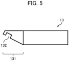
- Fig. 5 is a side diagram showing a shape of a tip end portion of the first member 13 or the second member 14. At least one of the first and second members 13 and 14 may be configured to have the tip end portion as shown in Fig. 5 . Although Fig. 5 exemplarily shows the tip end portion of the first member 13, the second member 14 may also have the same structure. Alternatively, only the second member 14 may have the same structure. Other configurations are the same as in the first embodiment.
- the tip end portion of the first member 13 has a tapered part 131 with a tapered tip end.
- the inclined portion of the tapered part 131 further has a recess 132.
- the tapered part 131 can be made of, for example, a resin material.
- the tapered part 131 and the recess 132 can be used to perform the following operations. The same is true for the second member 14.
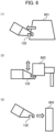
- Fig. 6 shows an exemplary operation that can be performed using the tapered part 131.
- the gripping device 1 can perform various operations using the tapered part 131.
- Fig. 6 shows some examples of such operations.
- Fig. 6(1) When the gripping device 1 accesses an object housed in a drawer structure 601, the recess 132 is hooked onto a slit portion of the drawer structure 601, and the drawer structure 601 is pulled forward as it is. This makes it possible to access the object housed in the drawer structure 601. It is also possible to push the pulled object back to its original position by the tapered part 131.
- a jig 602 can be supported from below and raised and lowered by the tapered part 131. At this time, when the jig 602 is positioned so that part of the jig 602 fits into the recess 132, a position of the jig 602 is more desirably stabilized.
- Fig. 6(3) A button can be pressed by the tapered part 131.
- the tapered part 131 can be pressed to a door 603, which opens and closes when pushed in, to open and close the door 603.
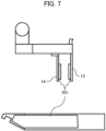
- Fig. 7 shows an exemplary elastic body 701 to clamp the object 2.
- the upper side of Fig. 7 shows a side view of the gripping device 1, and the lower side thereof shows a side view of the first member 13 (or the second member 14).
- the elastic body 701 may be attached to the side surface, on a side on which the target object 2 is clamped, of at least one of the first and second members 13 and 14 (both in Fig. 7 ).
- the elastic body 701 acts as an anti-slip material when the object 2 is gripped.
- the elastic body 701 can be made of a material that exerts a certain degree of frictional force when the object 2 is gripped.
- the elastic body 701 is attached so as to include at least part of an area, in which the target object 2 is gripped, of the first member 13 (or the second member 14). Other configurations are the same as in the first embodiment.
- a posture of the object 2 may be unstable.
- Using a certain soft material for the elastic body 701 makes it possible to stably grip the object 2 because when the object 2 is gripped, the elastic body 701 becomes dented, which leads to gripping operation in a manner of wrapping around the object 2. Furthermore, a gripping state can be further stabilized by using a material, which acts a certain frictional force with respect to the object 2, for the elastic body 701.
- Fig. 8 shows an exemplary operation that can be performed using the resin component 15.
- the gripping device 1 can use the resin component 15 to perform various operations. Fig. 8 shows some examples of such operations.
- the resin component 15 has a first protrusion 151 protruding from the arm part 12.
- the first protrusion 151 protrudes from the arm part 12 in a direction opposite to the extending direction of the first member 13.
- the resin component 15 further has a second protrusion 152.
- the second protrusion 152 is disposed at the tip end of the first protrusion 151.
- the second protrusion 152 protrudes in a direction opposite to the direction from the first member 13 toward the second member 14.
- the first protrusion 151 and the second protrusion 152 allow operations exemplified below to be performed.
- the gripping device 1 has the same configuration as in the above embodiments.
- Fig. 8(1) The door 801 can be opened by hooking the second protrusion 152 onto a groove (grip) of the door 801 and pulling the door 801.
- Fig. 8(2) The door 802 can be closed by pushing the door 802 with the resin component 15. Although certain force is applied to the door 802 by the pushing operation, there is almost no risk of damaging the door 802 because the resin component 15 is made of a resin material.
- FIG. 8(3) A drawer structure 803 can be pulled out by hooking the second protrusion 152 onto a groove (grip) of the drawer structure 803 and pulling the drawer structure 803.
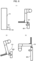
- Fig. 9 illustrates a distance between the arm part 12 and a point of force.
- the figure shows an exemplary operation of pulling the drawer structure 803.
- the drawer structure 803 is pulled with the resin component 15 (upper side of Fig. 9 )
- a small moment acts on the gripping device 1 due to a short distance between the point of force and the arm part 12.
- an operation with a higher load can be performed.
- the drawer structure 803 is pulled by the first member 13 (or second member 14) (lower side of Fig. 9 )
- the distance between the point of force and the arm part 12 is longer than that in the upper side of Fig. 9
- a larger moment than that in the upper side of Fig. 9 acts on the gripping device 1.
- only an operation with a lower load can be performed.
- a fourth embodiment of the disclosure describes modifications of the respective parts of the gripping device 1. Since other configurations are the same as those in the above embodiments, differences from the above embodiments are mainly described below.
- Fig. 10 is a side diagram showing an exemplary configuration of the gripping device 1 according to the fourth embodiment.
- At least one of the first and second members 13 and 14 may have a material 1001 such as silicone rubber attached to its tip end.
- the material 1001 makes it possible to operate a capacitive touch panel, for example.
- the material 1001 may be made of another rubber material and used as an anti-slip material to grip the object 2.
- the material 1001 can play the same role as the elastic body 701.
- Fig. 11 shows an exemplary configuration to reduce rigidity of the second member 14.
- Part of the second member 14 may be formed as a hollow 141 to make the rigidity of the second member 14 lower than the rigidity of the first member 13.
- the hollow 141 does not necessarily have to penetrate the second member 14, and the same effect can also be achieved by denting part of the rectangular portion of the second member 14. Such a dent will also be referred to as the hollow 141.
- Fig. 12 shows another exemplary configuration to reduce the rigidity of the second member 14. Even if the first member 13 and the second member 14 are made of the same material, the second member 14 has lower rigidity by making the second member 14 thinner than the first member 13. This makes it possible to achieve the configuration described in the first embodiment.
- Fig. 13 shows an exemplary operation to grip an object 2 having a recess.
- the gripping device 1 moves the tip end of each of the first and second members 13 and14 to the same height position as the inner wall of the recess ( Fig. 13(1) ).
- the gripping device 1 moves the arm part 12 so as to press the first member 13 to one inner wall of the recess ( Fig. 13 (2)).
- the gripping device 1 moves the second member 14 so as to press the second member 14 to the other inner wall of the recess ( Fig. 13 (3)).
- the object 2 can be gripped from the inside of the recess.
- Fig. 14 shows an exemplary configuration with a strain sensor 1401 attached.
- the strain sensor 1401 is attached to at least one of the first and second members 13 and 14. Based on detection results of the strain sensor 1401, the gripping device 1 can detect a gripping state of the object 2 (e.g., whether the object 2 is being gripped, strength of gripping force, etc.).
- the strain sensor 1401 is attached to each of the first and second members 13 and 14.
- the strain sensor 1401 should be attached only to the second member 14.
- Fig. 15 shows an example where an elastic body 162 is disposed between the second member 14 and the arm part 12. Connection is made between the arm part 12 and the second member 14 via a region 122 protruding from the arm part 12 and the elastic body 162.
- the second member 14 includes the elastic body 162.
- the second member 14 is pressed to the object 2, so that the elastic body 162 becomes flattened (lower side of Fig. 15 ). This makes it possible to grip the object 2 without changing the reference position of the gripping operation.
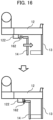
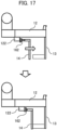
- Figs. 16 and 17 show modifications of the elastic body 162.
- the elastic body 162 may be formed of a spring ( Fig. 16 ) or a damper ( Fig. 17 ). In either configuration, the same effect as that in Fig. 15 can be achieved.
- Fig. 18 shows a modification of the recess 132.
- Examples of a shape of the recess 132 include: a curved surface ( Fig. 18(1) ); a V-shaped notch ( Fig. 18(2) ); a depression opened to the root of the tapered part 131 ( Fig. 18(3) ); and a triangular notch formed by two sides with different lengths ( Fig. 18(4) ).
- the disclosure is not limited to the above embodiments, but includes various modifications.
- the above embodiments have been described in detail to clearly explain the disclosure, and not all the described configurations are necessarily required to be included.
- Part of one embodiment can be replaced with a configuration of another embodiment.
- a configuration of one embodiment can be added to a configuration of another embodiment.
- part of a configuration of one embodiment can be added to, deleted from, or replaced with part of a configuration of another embodiment.
- each operation performed by the gripping device 1 can be implemented by, for example, storing data, which describes the amount of movement of each region for each operation step, in advance in a storage device, and instructing a combination of the operation steps.
- data which describes the amount of movement of each region for each operation step
- mechanisms such as an electric actuator, a pneumatic cylinder, and a hydraulic cylinder can each be used as a driving mechanism for sliding the second member 14 along the arm part 12.
- the resin component 15 is described to be attached to the first region 121 at the tip end of the arm part 12 in the above embodiments, the front surface (the surface of the resin component 15 as viewed from the right side of Fig. 1 ) of the resin component 15 and the front surface (the surface of the arm part 12 as viewed from the right side of Fig. 1 ) of the arm part 12 do not necessarily have to be on the same plane.
- the resin component 15 may be disposed at a position slightly away from the first region 121 toward the main body 11. In other words, the disposed position of the resin component 15 may be slightly changed within a range where operation performed by the resin component 15 is not hindered.
- a component similar to the resin component 15 may be added to the upper surface of the arm part 12 (the upper-side surface of the arm part 12 in Fig. 1 ) to perform the same operation as in each of the above embodiments.
- the material of the resin component 15 may be changed as long as each operation described in the above embodiments can be performed.
- a rubber material may be used.
- the front surface of the first member 13 and the front surface of the arm part 12 do not necessarily have to be on the same plane, as with the resin component 15.
Landscapes
- Engineering & Computer Science (AREA)
- Robotics (AREA)
- Mechanical Engineering (AREA)
- Manipulator (AREA)
Abstract
The purpose of the present disclosure is to, with respect to a gripping device that grips an object, provide utility that enables a gripping action and various tasks to be performed. A gripping device according to the present disclosure comprises a first member and a second member that extend from an arm part. The first member and the second member are configured so as to grip an object by sandwiching the object. The rigidity of the first member is greater than the rigidity of the second member.
Description
- The present disclosure relates to a gripping device to grip an object.
- Work automation by a robot is a useful method for improving work efficiency. Various types of work are performed by robots depending on automation objects. The structure of the robot also has various forms depending on the various types of work.
-
Patent Literature 1 describes a robot hand with a mechanism for moving at least one of finger parts, i.e., a first finger part and a second finger part, along an opposite direction of the first and second finger parts (see abstract). - Patent Literature 1:
Japanese Unexamined Patent Application Publication No. 2019-202370 - The structure of a robot is desirably optimized according to work to be performed by the robot. On the other hand, if the structure of a robot is optimized for specific work, the robot becomes less versatile, making it difficult to automate work other than the specific work. A robot like that in
Patent Literature 1 is usually optimized for the work to be performed thereby, and is thus less likely to perform various types of work. - An object of the present invention is therefore to allow a gripping device for gripping an object to perform various types of work in addition to gripping operation.
- A gripping device according to the disclosure includes a first member and a second member, each extending from an arm part, configured to grip an object between them, where the first member has higher rigidity than the second member.
- The gripping device of the disclosure can provide versatility to allow various types of work to be performed in addition to gripping operation. Other problems, configurations, and advantageous effects will be clarified by the following description of some embodiments.
-
-
Fig. 1 is a side diagram showing a configuration of agripping device 1 according to a first embodiment. -
Fig. 2 Illustrates a process of gripping anobject 2 by thegripping device 1. -
Fig. 3 is an illustration of rigidity of afirst member 13 and rigidity of asecond member 14. -
Fig. 4 shows an exemplary member connecting between thesecond member 14 and anarm part 12. -
Fig. 5 is a side diagram showing a shape of a tip end portion of the first orsecond member -
Fig. 6 shows an exemplary operation that can be performed using atapered part 131. -
Fig. 7 shows an exemplaryelastic body 701 to clamp theobject 2. -
Fig. 8 shows an exemplary operation that can be performed using aresin component 15. -
Fig. 9 illustrates a distance between thearm part 12 and a point of force. -
Fig. 10 is a side view showing an exemplary configuration of agripping device 1 according to a fourth embodiment. -
Fig. 11 shows an exemplary configuration to reduce rigidity of thesecond member 14. -
Fig. 12 shows another exemplary configuration to reduce the rigidity of thesecond member 14. -
Fig. 13 shows an exemplary operation to grip anobject 2 having a recess. -
Fig. 14 shows an exemplary configuration with astrain sensor 1401 attached. -
Fig. 15 shows an example where anelastic body 162 is disposed between thesecond member 14 and thearm part 12. -
Fig. 16 shows a modification of theelastic body 162. -
Fig. 17 shows another modification of theelastic body 162. -
Fig. 18 shows a modification of arecess 132. -
Fig. 1 is a side diagram showing a configuration of agripping device 1 according to a first embodiment of the disclosure. Thegripping device 1 grips an object. The gripping device 1 (robot) includes amain body 11, anarm part 12, afirst member 13, asecond member 14, and aresin component 15. - The
main body 11 is a main body part of thegripping device 1. Thearm part 12, which extends from themain body 11, can perform various motions (e.g., rotary motion) by themain body 11, for example. Thefirst member 13 is attached to afirst region 121, which is the tip end of thearm part 12, and extends approximately perpendicular to an extending direction of the arm part 12 (at least in a direction nonparallel to the extending direction of the arm part 12). Thesecond member 14 is attached to thearm part 12 at a slight distance from thefirst member 13, and extends in substantially the same direction as the first member 13 (at least in a direction nonparallel to the extending direction of the arm part 12). - The
first member 13 is fixed in position with respect to thearm part 12. Thesecond member 14 can move along the extending direction of thearm part 12. Thefirst member 13 has higher rigidity than thesecond member 14. For example, thefirst member 13 can be made of steel use stainless (SUS) and thesecond member 14 can be made of aluminum, but the materials are not necessarily limited to those. -
Fig. 2 Illustrates a process of gripping theobject 2 by thegripping device 1. In an initial state, thearm part 12 is disposed above theobject 2. Thegripping device 1 moves thesecond member 14 in a direction away from the first member 13 (Fig. 2(1) ). Thegripping device 1 moves thearm part 12 downward (closer to the object 2) (Fig. 2(2) ). Thegripping device 1 moves thearm part 12 to bring a side surface of thefirst member 13 into contact with a side surface of the object 2 (Fig. 2(3) ). Thegripping device 1 moves thesecond member 14 in a direction closer to the first member 13 (Fig. 2(4) ). Through such operations, thefirst member 13 and thesecond member 14 clamp theobject 2, allowing theobject 2 to be gripped. -
Fig. 3 is an illustration of rigidity of each of the first andsecond members first member 13 has higher rigidity (upper side ofFig. 3 ), since thesecond member 14 bends when thefirst member 13 and thesecond member 14 grip theobject 2, theobject 2 is gripped with thefirst member 13 as a reference position that is unchanged. As a result, thegripping device 1 has high operation reproducibility. If both have the same rigidity (middle side ofFig. 3 ), since both thefirst member 13 and thesecond member 14 bend when theobject 2 is gripped, the reference position for gripping changes from thefirst region 121, and thus operational reproducibility of thegripping device 1 is lower than that in the upper side ofFig. 3 . If thesecond member 14 has higher rigidity (lower side ofFig. 3 ), since thefirst member 13 bends when theobject 2 is gripped, the reference position for gripping changes from thefirst region 121, and thus operational reproducibility of thegripping device 1 is lower than that in the upper side ofFig. 3 . Therefore, when the first region 121 (i.e., the first member 13) is set as the reference position, thefirst member 13 desirably has higher rigidity than thesecond member 14. -
Fig. 4 shows an exemplary member connecting between thesecond member 14 and thearm part 12. Connection can be made between thesecond member 14 and thearm part 12 by anelastic body 161. In other words, thesecond member 14 inFig. 4 has theelastic body 161. Thesecond member 14 has an L shape, and theelastic body 161 extends along thearm part 12 in a direction opposite to the direction toward thefirst member 13. When thesecond member 14 is moved toward the first member 13 (the upper surface of theelastic body 161 is slid toward the first member 13), theelastic body 161 is deformed as shown in the lower side ofFig. 4 . As a result, the reference position of the gripping operation does not change from thefirst region 121. - In the configuration of
Fig. 4 , thesecond member 14 excluding theelastic body 161 may have approximately the same rigidity as thefirst member 13. This is because since theelastic body 161 of thesecond member 14 has lower rigidity than thefirst member 13, when clamping theobject 2, thesecond member 14 as a whole has lower rigidity than thefirst member 13. - The
gripping device 1 according to the first embodiment has thefirst member 13 and thesecond member 14 extending from thearm part 12, and is configured to be capable of gripping theobject 2 by thefirst member 13 and thesecond member 14, where thefirst member 13 has higher rigidity than thesecond member 14. This makes it possible to achieve reproducible gripping operation without changing the reference position of the gripping operation. - In the
gripping device 1 of the first embodiment, thefirst member 13 and thesecond member 14 can take various postures by thearm part 12 and the main body 11 (a driving mechanism to change a posture of the arm part 12). This makes it possible to perform various types of operations by the tip end of the first member 13 (or the second member 14), for example. Specific operation examples will be described in the following embodiments, respectively. -
Fig. 5 is a side diagram showing a shape of a tip end portion of thefirst member 13 or thesecond member 14. At least one of the first andsecond members Fig. 5 . AlthoughFig. 5 exemplarily shows the tip end portion of thefirst member 13, thesecond member 14 may also have the same structure. Alternatively, only thesecond member 14 may have the same structure. Other configurations are the same as in the first embodiment. - The tip end portion of the
first member 13 has a taperedpart 131 with a tapered tip end. The inclined portion of thetapered part 131 further has arecess 132. Thetapered part 131 can be made of, for example, a resin material. Thetapered part 131 and therecess 132 can be used to perform the following operations. The same is true for thesecond member 14. -
Fig. 6 shows an exemplary operation that can be performed using thetapered part 131. Thegripping device 1 can perform various operations using thetapered part 131.Fig. 6 shows some examples of such operations. -
Fig. 6(1) : When thegripping device 1 accesses an object housed in adrawer structure 601, therecess 132 is hooked onto a slit portion of thedrawer structure 601, and thedrawer structure 601 is pulled forward as it is. This makes it possible to access the object housed in thedrawer structure 601. It is also possible to push the pulled object back to its original position by thetapered part 131. -
Fig. 6(2) : Ajig 602 can be supported from below and raised and lowered by thetapered part 131. At this time, when thejig 602 is positioned so that part of thejig 602 fits into therecess 132, a position of thejig 602 is more desirably stabilized. -
Fig. 6(3) : A button can be pressed by thetapered part 131. Alternatively, thetapered part 131 can be pressed to adoor 603, which opens and closes when pushed in, to open and close thedoor 603. -
Fig. 7 shows an exemplaryelastic body 701 to clamp theobject 2. The upper side ofFig. 7 shows a side view of thegripping device 1, and the lower side thereof shows a side view of the first member 13 (or the second member 14). Theelastic body 701 may be attached to the side surface, on a side on which thetarget object 2 is clamped, of at least one of the first andsecond members 13 and 14 (both inFig. 7 ). Theelastic body 701 acts as an anti-slip material when theobject 2 is gripped. Theelastic body 701 can be made of a material that exerts a certain degree of frictional force when theobject 2 is gripped. Theelastic body 701 is attached so as to include at least part of an area, in which thetarget object 2 is gripped, of the first member 13 (or the second member 14). Other configurations are the same as in the first embodiment. - If the
object 2 is gripped without theelastic body 701 attached, insufficient force to clamp theobject 2 leads to a body position at which theobject 2 is clamped only at application points, and thus a posture of theobject 2 may be unstable. Using a certain soft material for theelastic body 701 makes it possible to stably grip theobject 2 because when theobject 2 is gripped, theelastic body 701 becomes dented, which leads to gripping operation in a manner of wrapping around theobject 2. Furthermore, a gripping state can be further stabilized by using a material, which acts a certain frictional force with respect to theobject 2, for theelastic body 701. -
Fig. 8 shows an exemplary operation that can be performed using theresin component 15. Thegripping device 1 can use theresin component 15 to perform various operations.Fig. 8 shows some examples of such operations. Theresin component 15 has afirst protrusion 151 protruding from thearm part 12. Thefirst protrusion 151 protrudes from thearm part 12 in a direction opposite to the extending direction of thefirst member 13. Theresin component 15 further has asecond protrusion 152. Thesecond protrusion 152 is disposed at the tip end of thefirst protrusion 151. Thesecond protrusion 152 protrudes in a direction opposite to the direction from thefirst member 13 toward thesecond member 14. Thefirst protrusion 151 and thesecond protrusion 152 allow operations exemplified below to be performed. Thegripping device 1 has the same configuration as in the above embodiments. -
Fig. 8(1) : Thedoor 801 can be opened by hooking thesecond protrusion 152 onto a groove (grip) of thedoor 801 and pulling thedoor 801. -
Fig. 8(2) : Thedoor 802 can be closed by pushing thedoor 802 with theresin component 15. Although certain force is applied to thedoor 802 by the pushing operation, there is almost no risk of damaging thedoor 802 because theresin component 15 is made of a resin material. -
Fig. 8(3) : Adrawer structure 803 can be pulled out by hooking thesecond protrusion 152 onto a groove (grip) of thedrawer structure 803 and pulling thedrawer structure 803. -
Fig. 9 illustrates a distance between thearm part 12 and a point of force. The figure shows an exemplary operation of pulling thedrawer structure 803. When thedrawer structure 803 is pulled with the resin component 15 (upper side ofFig. 9 ), a small moment acts on thegripping device 1 due to a short distance between the point of force and thearm part 12. As a result, an operation with a higher load can be performed. When thedrawer structure 803 is pulled by the first member 13 (or second member 14) (lower side ofFig. 9 ), since the distance between the point of force and thearm part 12 is longer than that in the upper side ofFig. 9 , a larger moment than that in the upper side ofFig. 9 acts on thegripping device 1. As a result, only an operation with a lower load can be performed. In view of the above, when an operation with a high load is performed, it will be desirable to perform the operation in the upper side ofFig. 9 (with the resin component 15). - A fourth embodiment of the disclosure describes modifications of the respective parts of the
gripping device 1. Since other configurations are the same as those in the above embodiments, differences from the above embodiments are mainly described below. -
Fig. 10 is a side diagram showing an exemplary configuration of thegripping device 1 according to the fourth embodiment. At least one of the first andsecond members material 1001 makes it possible to operate a capacitive touch panel, for example. Alternatively, thematerial 1001 may be made of another rubber material and used as an anti-slip material to grip theobject 2. In this case, thematerial 1001 can play the same role as theelastic body 701. -
Fig. 11 shows an exemplary configuration to reduce rigidity of thesecond member 14. Part of thesecond member 14 may be formed as a hollow 141 to make the rigidity of thesecond member 14 lower than the rigidity of thefirst member 13. As a result, even if thefirst member 13 and thesecond member 14 are made of the same material, thesecond member 14 has a lower rigidity. This makes it possible to achieve the configuration described in the first embodiment. The hollow 141 does not necessarily have to penetrate thesecond member 14, and the same effect can also be achieved by denting part of the rectangular portion of thesecond member 14. Such a dent will also be referred to as the hollow 141. -
Fig. 12 shows another exemplary configuration to reduce the rigidity of thesecond member 14. Even if thefirst member 13 and thesecond member 14 are made of the same material, thesecond member 14 has lower rigidity by making thesecond member 14 thinner than thefirst member 13. This makes it possible to achieve the configuration described in the first embodiment. -
Fig. 13 shows an exemplary operation to grip anobject 2 having a recess. Thegripping device 1 moves the tip end of each of the first andsecond members 13 and14 to the same height position as the inner wall of the recess (Fig. 13(1) ). Thegripping device 1 moves thearm part 12 so as to press thefirst member 13 to one inner wall of the recess (Fig. 13 (2)). Thegripping device 1 moves thesecond member 14 so as to press thesecond member 14 to the other inner wall of the recess (Fig. 13 (3)). As a result, theobject 2 can be gripped from the inside of the recess. -
Fig. 14 shows an exemplary configuration with astrain sensor 1401 attached. InFig. 14 , thestrain sensor 1401 is attached to at least one of the first andsecond members strain sensor 1401, thegripping device 1 can detect a gripping state of the object 2 (e.g., whether theobject 2 is being gripped, strength of gripping force, etc.). In the case of using a type of sensor, which detects strain of thesecond member 14 from a difference between strain of thefirst member 13 and the strain of thesecond member 14, thestrain sensor 1401 is attached to each of the first andsecond members second member 14 alone, thestrain sensor 1401 should be attached only to thesecond member 14. -
Fig. 15 shows an example where anelastic body 162 is disposed between thesecond member 14 and thearm part 12. Connection is made between thearm part 12 and thesecond member 14 via aregion 122 protruding from thearm part 12 and theelastic body 162. In other words, thesecond member 14 includes theelastic body 162. Thesecond member 14 is pressed to theobject 2, so that theelastic body 162 becomes flattened (lower side ofFig. 15 ). This makes it possible to grip theobject 2 without changing the reference position of the gripping operation. -
Figs. 16 and17 show modifications of theelastic body 162. Theelastic body 162 may be formed of a spring (Fig. 16 ) or a damper (Fig. 17 ). In either configuration, the same effect as that inFig. 15 can be achieved. -
Fig. 18 shows a modification of therecess 132. Examples of a shape of therecess 132 include: a curved surface (Fig. 18(1) ); a V-shaped notch (Fig. 18(2) ); a depression opened to the root of the tapered part 131 (Fig. 18(3) ); and a triangular notch formed by two sides with different lengths (Fig. 18(4) ). - The disclosure is not limited to the above embodiments, but includes various modifications. For example, the above embodiments have been described in detail to clearly explain the disclosure, and not all the described configurations are necessarily required to be included. Part of one embodiment can be replaced with a configuration of another embodiment. A configuration of one embodiment can be added to a configuration of another embodiment. For each embodiment, part of a configuration of one embodiment can be added to, deleted from, or replaced with part of a configuration of another embodiment.
- In the above embodiments, each operation performed by the
gripping device 1 can be implemented by, for example, storing data, which describes the amount of movement of each region for each operation step, in advance in a storage device, and instructing a combination of the operation steps. For example, it is only necessary to instruct thegripping device 1 to perform each of steps (1) to (4) inFig. 2 in the order shown inFig. 2 while data, which specify the amount of movement of each region in each of the steps, are stored in advance. - In the above embodiments, mechanisms such as an electric actuator, a pneumatic cylinder, and a hydraulic cylinder can each be used as a driving mechanism for sliding the
second member 14 along thearm part 12. - Although the
resin component 15 is described to be attached to thefirst region 121 at the tip end of thearm part 12 in the above embodiments, the front surface (the surface of theresin component 15 as viewed from the right side ofFig. 1 ) of theresin component 15 and the front surface (the surface of thearm part 12 as viewed from the right side ofFig. 1 ) of thearm part 12 do not necessarily have to be on the same plane. For example, theresin component 15 may be disposed at a position slightly away from thefirst region 121 toward themain body 11. In other words, the disposed position of theresin component 15 may be slightly changed within a range where operation performed by theresin component 15 is not hindered. A component similar to theresin component 15 may be added to the upper surface of the arm part 12 (the upper-side surface of thearm part 12 inFig. 1 ) to perform the same operation as in each of the above embodiments. The material of theresin component 15 may be changed as long as each operation described in the above embodiments can be performed. For example, a rubber material may be used. - Although the
first member 13 is described to be attached to thefirst region 121 in the above embodiments, the front surface of thefirst member 13 and the front surface of thearm part 12 do not necessarily have to be on the same plane, as with theresin component 15. -
- 1: gripping device
- 11: main body
- 12: arm part
- 13: first member
- 14: second member
- 15: resin component
Claims (17)
- A gripping device to grip an object, comprising:an arm part;a first member fixed to a first region at an end of the arm part, and extending in a direction nonparallel to an extending direction of the arm part with the first region as a start point; anda second member disposed in parallel with the first member and movable along the arm part,wherein the first member and the second member are configured to be capable of clamping and gripping the object, andthe first member and the second member are configured to respectively have rigidities, the rigidity of the first member being higher than the rigidity of the second member.
- The gripping device according to claim 1,wherein the second member has a first elastic body,connection is made between the arm part and the second member through connection of the first elastic body and the arm part, andthe first elastic body extends in a direction opposite to a direction from the second member toward the first member, thereby the second member forms an L shape.
- The gripping device according to claim 1,wherein at least one of regions has a recess, the regions includinga second region being a tip end of the first member on a side where the first member is unconnected to the arm part,
anda third region being a tip end of the second member on a side where the second member is unconnected to the arm part. - The gripping device according to claim 3,wherein the first member and the second member are each a rectangular member extending from the arm part,the second region and the third region are each a tapered region disposed at a tip end of the rectangular member, andthe recess is formed in the tapered region.
- The gripping device according to claim 3,
wherein a second elastic body is attached to at least one of respective surfaces of the second region and the third region, the surfaces being opposed to each other. - The gripping device according to claim 1,
further comprising a first protrusion formed to protrude from the arm part in a direction opposite to the extending direction of the first member in the first region. - The gripping device according to claim 6,
wherein the first protrusion includes a second protrusion formed to protrude in a direction nonparallel to the direction in which the first protrusion protrudes from the arm part and in a direction opposite to a direction from the first member toward the second member. - The gripping device according to claim 6,
wherein length of the first protrusion protruding from the arm part is shorter than length of the first member or the second member protruding from the arm part. - The gripping device according to claim 3,
wherein at least one of the second and third regions is configured of an elastic body. - The gripping device according to claim 1,wherein the first member and the second member are formed of the same material, andthe second member has a hollow portion or is thinner than the first member, thereby the first and second members are configured to respectively have rigidities, the rigidity of the first member being higher than the rigidity of the second member.
- The gripping device according to claim 1,
further comprising a strain sensor that detects deflection of the second member and thus detects a gripping state of the object by the first member and the second member. - The gripping device according to claim 1,wherein the second member has a second elastic body,connection is made between the arm part and the second member through connection of a member protruding from the arm part and the second elastic body, andthe second elastic body is disposed to contract depending on strength of clamping when the first and second members grip the object by clamping the object.
- The gripping device according to claim 3,wherein the recess includes at least one of dents,the dents including a curved dent, an isosceles triangular dent, a dent formed by two sides with different lengths of a triangle, and a rectangular dent.
- The gripping device according to claim 4,
wherein the gripping device performs at least one of operations including:pulling a drawer structure out by hooking the recess onto a slit of the drawer structure;raising and lowering the arm part while supporting an object by the recess; andpressing a button or opening and closing a door, the door opening and closing when pushed in, by the second or third region. - The gripping device according to claim 7,
wherein the gripping device performs at least one of operations including:opening a door by hooking the second protrusion onto a grip of the door;closing the door by pushing the door by the first or second protrusion; andpulling a drawer structure out by hooking the second protrusion onto a slit of the drawer structure. - The gripping device according to claim 1,wherein the object has a second recess, andthe gripping devicepresses the first member to one of inner walls of the second recess, andmoves the second member in a direction away from the first member, thereby presses the second member to the other of the inner walls of the second recess,thereby grips the object via the second recess.
- The gripping device according to claim 1,further comprising a driving mechanism to change a posture of the arm part, andthe driving mechanism is configured to be capable of changing a type of operation performed by the gripping device by changing the posture of the arm part.
Applications Claiming Priority (2)
| Application Number | Priority Date | Filing Date | Title |
|---|---|---|---|
| JP2022119217 | 2022-07-27 | ||
| PCT/JP2023/025005 WO2024024436A1 (en) | 2022-07-27 | 2023-07-05 | Gripping device |
Publications (2)
| Publication Number | Publication Date |
|---|---|
| EP4563305A1 true EP4563305A1 (en) | 2025-06-04 |
| EP4563305A4 EP4563305A4 (en) | 2026-07-22 |
Family
ID=89706117
Family Applications (1)
| Application Number | Title | Priority Date | Filing Date |
|---|---|---|---|
| EP23844531.6A Pending EP4563305A4 (en) | 2022-07-27 | 2023-07-05 | GRIPPING DEVICE |
Country Status (4)
| Country | Link |
|---|---|
| EP (1) | EP4563305A4 (en) |
| JP (1) | JP7810803B2 (en) |
| CN (1) | CN119522154A (en) |
| WO (1) | WO2024024436A1 (en) |
Family Cites Families (14)
| Publication number | Priority date | Publication date | Assignee | Title |
|---|---|---|---|---|
| CA1276710C (en) * | 1983-11-30 | 1990-11-20 | Kazuo Asakawa | Robot force controlling system |
| JPH11221788A (en) * | 1998-02-09 | 1999-08-17 | Sony Corp | Clamping device and method of using the same |
| JP2004345043A (en) * | 2003-05-23 | 2004-12-09 | Canon Inc | Object gripping mechanism |
| JP2008178968A (en) * | 2006-12-25 | 2008-08-07 | Yaskawa Electric Corp | Robot hand |
| JP5057449B2 (en) * | 2007-09-12 | 2012-10-24 | 国立大学法人広島大学 | Robot hand |
| JP4834767B2 (en) * | 2009-12-10 | 2011-12-14 | 株式会社アイ.エス.テイ | Grasping device, fabric processing robot, and fabric processing system |
| JP2015166121A (en) * | 2014-03-04 | 2015-09-24 | セイコーエプソン株式会社 | Holding method for robot hand, robot, and clamping workpiece |
| JP6594024B2 (en) * | 2015-05-07 | 2019-10-23 | ヤマト科学株式会社 | Sample processing system |
| JP6920064B2 (en) * | 2017-01-13 | 2021-08-18 | 株式会社アマダ | Robot hand and articulated robot |
| JP6914475B2 (en) * | 2017-05-18 | 2021-08-04 | Smc株式会社 | Work gripping device |
| JP6587325B1 (en) | 2018-05-22 | 2019-10-09 | 日本金銭機械株式会社 | Robot hand and transfer device |
| JP7360623B2 (en) * | 2020-01-08 | 2023-10-13 | オムロン株式会社 | robot hand |
| DE102020105689A1 (en) * | 2020-03-03 | 2021-09-09 | GWK Präzisionstechnik GmbH | Gripping system |
| CN212887678U (en) * | 2020-08-18 | 2021-04-06 | 中乌先楚核能科技有限公司 | A manipulator structure for narrow space snatchs heavy object |
-
2023
- 2023-07-05 CN CN202380052560.9A patent/CN119522154A/en active Pending
- 2023-07-05 JP JP2024536906A patent/JP7810803B2/en active Active
- 2023-07-05 EP EP23844531.6A patent/EP4563305A4/en active Pending
- 2023-07-05 WO PCT/JP2023/025005 patent/WO2024024436A1/en not_active Ceased
Also Published As
| Publication number | Publication date |
|---|---|
| CN119522154A (en) | 2025-02-25 |
| JP7810803B2 (en) | 2026-02-03 |
| JPWO2024024436A1 (en) | 2024-02-01 |
| WO2024024436A1 (en) | 2024-02-01 |
| EP4563305A4 (en) | 2026-07-22 |
Similar Documents
| Publication | Publication Date | Title |
|---|---|---|
| US8276957B2 (en) | Robot hand and finger mechanism | |
| EP3831552B1 (en) | End effector device | |
| JPH0679680A (en) | Robot gripping device | |
| CN113561190B (en) | Mechanical gripper control method, device, electronic device, gripper and robot | |
| CN212287675U (en) | Under-actuated gripper | |
| EP3831549B1 (en) | End effector device | |
| CN113631330A (en) | Teaching retention force for an article in a robotic gripper | |
| CN115151388B (en) | Robotic Hand | |
| CN114800541B (en) | Cable terminal detection method and robot | |
| KR20210101450A (en) | Variable rigid gripper with mre, electromagnet and spring, method for picking up atypical objects using thereof | |
| CN115210050B (en) | Robot hand | |
| JP2017030059A (en) | Robot control device, robot and robot system | |
| EP4008501B1 (en) | Parallel gripper with adaptive clamping surfaces | |
| CN116372972B (en) | A power-free, flexible gripper for adaptive gripping | |
| JP7810803B2 (en) | gripping device | |
| CN115151387B (en) | robotic arm | |
| Gutierrez et al. | Development of Wire Actuated Monolithic Soft Gripper Positioned by Robot Manipulator | |
| JP2020097066A (en) | Gripping device | |
| US20250091229A1 (en) | Robot hand and operation method for robot hand | |
| JP2001062771A (en) | Toggle type fluid pressure holding device | |
| US20250289113A1 (en) | Apparatus | |
| Khalid et al. | Universal Gripper for Industrial Manipulation With Enhanced Rigid Mechanics and Self‐Adaptable Fingers | |
| JPH05123987A (en) | Gripping device | |
| JPWO2024024436A5 (en) | ||
| SU1569229A1 (en) | Manipulator grip |
Legal Events
| Date | Code | Title | Description |
|---|---|---|---|
| STAA | Information on the status of an ep patent application or granted ep patent |
Free format text: STATUS: THE INTERNATIONAL PUBLICATION HAS BEEN MADE |
|
| PUAI | Public reference made under article 153(3) epc to a published international application that has entered the european phase |
Free format text: ORIGINAL CODE: 0009012 |
|
| STAA | Information on the status of an ep patent application or granted ep patent |
Free format text: STATUS: REQUEST FOR EXAMINATION WAS MADE |
|
| 17P | Request for examination filed |
Effective date: 20241212 |
|
| AK | Designated contracting states |
Kind code of ref document: A1 Designated state(s): AL AT BE BG CH CY CZ DE DK EE ES FI FR GB GR HR HU IE IS IT LI LT LU LV MC ME MK MT NL NO PL PT RO RS SE SI SK SM TR |
|
| DAV | Request for validation of the european patent (deleted) | ||
| DAX | Request for extension of the european patent (deleted) | ||
| A4 | Supplementary search report drawn up and despatched |
Effective date: 20260616 |