EP4563289A1 - Work machine - Google Patents
Work machine Download PDFInfo
- Publication number
- EP4563289A1 EP4563289A1 EP23846415.0A EP23846415A EP4563289A1 EP 4563289 A1 EP4563289 A1 EP 4563289A1 EP 23846415 A EP23846415 A EP 23846415A EP 4563289 A1 EP4563289 A1 EP 4563289A1
- Authority
- EP
- European Patent Office
- Prior art keywords
- output
- transmission
- work machine
- clutch
- motor
- Prior art date
- Legal status (The legal status is an assumption and is not a legal conclusion. Google has not performed a legal analysis and makes no representation as to the accuracy of the status listed.)
- Pending
Links
Images













Classifications
-
- B—PERFORMING OPERATIONS; TRANSPORTING
- B25—HAND TOOLS; PORTABLE POWER-DRIVEN TOOLS; MANIPULATORS
- B25F—COMBINATION OR MULTI-PURPOSE TOOLS NOT OTHERWISE PROVIDED FOR; DETAILS OR COMPONENTS OF PORTABLE POWER-DRIVEN TOOLS NOT PARTICULARLY RELATED TO THE OPERATIONS PERFORMED AND NOT OTHERWISE PROVIDED FOR
- B25F5/00—Details or components of portable power-driven tools not particularly related to the operations performed and not otherwise provided for
- B25F5/001—Gearings, speed selectors, clutches or the like specially adapted for rotary tools
-
- B—PERFORMING OPERATIONS; TRANSPORTING
- B25—HAND TOOLS; PORTABLE POWER-DRIVEN TOOLS; MANIPULATORS
- B25F—COMBINATION OR MULTI-PURPOSE TOOLS NOT OTHERWISE PROVIDED FOR; DETAILS OR COMPONENTS OF PORTABLE POWER-DRIVEN TOOLS NOT PARTICULARLY RELATED TO THE OPERATIONS PERFORMED AND NOT OTHERWISE PROVIDED FOR
- B25F5/00—Details or components of portable power-driven tools not particularly related to the operations performed and not otherwise provided for
- B25F5/02—Construction of casings, bodies or handles
- B25F5/025—Construction of casings, bodies or handles with torque reaction bars for rotary tools
- B25F5/026—Construction of casings, bodies or handles with torque reaction bars for rotary tools in the form of an auxiliary handle
Definitions
- the invention relates to a work machine.
- Patent Documents 1 and 2 disclose work machines such as driver drills.
- Patent Document 3 discloses a work machine with a detachable handle.
- the work machine such as a driver drill includes a motor, a spindle, a transmission mechanism that transmits the rotation of the motor to the spindle, a chuck screwed to the spindle, a deceleration ratio switching mechanism that switches the deceleration ratio of the transmission mechanism, and a clutch mechanism that interrupts, at a predetermined torque, the rotation transmission from the transmission mechanism to the spindle.
- the deceleration ratio switching mechanism has a shift knob operated by the user and a shift arm for advancing and retracting a slide ring gear of a transmission mechanism in conjunction with the operation of the shift knob.
- a clutch mechanism has a clutch dial for the user to change a predetermined torque.
- a driver drill with a vibration function such as the one in Patent Document 2, is also referred to as a vibration driver drill, and the presence or absence of vibration can also be switched by operating the clutch dial.
- a chuck and a spindle are fixed with high torque, and a special jig is required to release the fixation.
- the chuck and the spindle substantially serve as an integral tip tool holding part. Therefore, it is difficult to replace parts that cannot be removed without releasing the fixation of the chuck and spindle.
- a conventional work machine has many parts that are difficult to replace, resulting in poor repairability.
- the first issue recognized by the inventor of the invention is to provide a work machine with good repairability.
- the drill mode with maximum torque is set by fixing a ring gear of the transmission mechanism to be not rotatable.
- a structure for setting the drill mode a structure is formed in which a nut that rotates with a clutch dial and moves axially pushes a stopper pin toward the ring gear side.
- a portion of the ring gear may be present in the extension of the stopper pin.
- the clutch dial becomes unable to rotate, making it not possible to transition to the drill mode.
- the second issue recognized by the inventor of the invention is to provide a work machine that can suppress the malfunction of being unable to make the ring gear non-rotatable.
- a work machine such as a driver drill
- a fixing part such as a screw
- the rigidity of the cases can be increased and deformation can be suppressed by fixing multiple cases.
- a shift arm passes the outer side of the fixing part in the radial direction of the case
- the size of the product increases in the radial direction.
- the fourth issue recognized by the inventor of the invention is to provide a work machine that can reduce the effort required to switch between vibration and non-vibration.
- a structure in which a handle is detachable to a work machine As a structure in which a handle is detachable to a work machine, a structure is known where an annular mounting part is provided with a gap (opening) in a portion in the peripheral direction is attached to the work machine in a way that closes the gap.
- the maximum length of the gap in the mounting part is the natural length, it may be difficult to attach or detach the handle.
- the fifth issue recognized by the inventor of the invention is to provide a handle that can be easily attached to and detached from the work machine, and a work machine provided with a handle that can be easily attached and detached.
- the sixth issue recognized by the inventor of the invention is to provide a handle that allows fine adjustment to the mounting state of the work machine, and a work machine provided with a handle that allows fine adjustment in the mounting state.
- An objective of the invention is to provide a work machine that at least solves the first issue among the above issues.
- An aspect of the invention provides a work machine.
- the work machine includes: an output part, having a tip tool holding part, and a bearing part supporting the tip tool holding part, the output part being positioned on one side of the motor in an axial direction of the motor; a transmission part, configured as a transmission part that transmits a driving force of the motor to the tip tool holding part, and detachably assembled to the output part from an other side in the axial direction to be positioned on the one side of the motor in the axial direction; and an output switching part, configured as an output switching part that switches an output of the output part, and disposed by being sandwiched between the output part and the transmission part.
- the output switching part is able to be removed from the output part toward the other side in the axial direction
- the invention may also be expressed as "electric work machine”, “electric tool”, or “electric device”, and such expressions are also valid as aspects of the invention.
- a work machine having solved at least the first issues among the above issues can be provided.
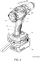
- An embodiment of the invention relates to a work machine 1.
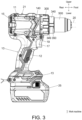
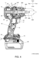
- the work machine 1 is a vibration driver drill. Based on FIGs. 3 and 4 , front-rear and up-down directions of the work machine 1 orthogonal to each other are defined. Additionally, the left-right direction, which is perpendicular to both the front-rear and up-lower directions, is defined based on an operator facing the front.
- the front-rear direction is parallel to the axial direction of a motor shaft 31.
- the front side corresponds to a side of the axial direction.
- the rear side corresponds to the other side of the axial direction.
- the up-lower direction is a direction that connects the motor accommodation part 11 and the battery pack mounting part 13 and is perpendicular to the front-rear direction.
- the work machine 1 includes a housing 10.
- the housing 10 is, for example, a resin molded body with a left-right split structure.
- the housing 10 has a motor accommodation part 11, a handle part 12, and a battery pack mounting part 13.
- the motor accommodation part 11 is a tubular part in which the central axis is parallel to the front-rear direction.
- the work machine 1 includes a tail cover 15 that covers a rear opening of the motor accommodation part 11.
- the work machine 1 includes a shift knob 21 on the upper part of the motor accommodation part 11.
- the shift knob 21 is a deceleration ratio switching operation part that rotates a shift arm 71 appearing in FIGs. 5 to 7 to move a slide ring gear 57 (to be described afterwards) forward and rearward, and switches the deceleration ratio of the transmission mechanism 50 shown in FIG. 5 .
- the shift arm 71 is, for example, made of metal and corresponds to the deceleration ratio switching part.
- the handle part 12 extends downward from the lower part of the motor accommodation part 11.
- the work machine 1 includes a trigger switch 17 at the upper end of the handle part 12.
- the trigger switch 17 is able to switch the motor 30 between drive and stop.
- the work machine 1 includes a forward-reverse switch 19 at a boundary portion between the motor accommodation part 11 and the handle part 12, and the forward-reverse switch 18 is able to switch the motor 30 between forward and reverse rotation.
- the battery pack mounting part 13 is connected to the lower end of the handle part 12.
- the battery pack mounting part 13 detachably mounts a battery pack 25 which serves as the power source for the work machine 1.
- the work machine 1 includes a control substrate part 23 inside the battery pack mounting part 13.
- the control substrate part 23 is equipped with a microcontroller that controls the drive of the motor 30, an inverter circuit for supplying current to the motor 30, among other components.
- the work machine 1 includes a motor 30, a fan 35, and a sensor substrate 37 inside the motor accommodation part 11.
- the motor 30 is, for example, an inner rotor type brushless motor and driven by the power from the battery pack 25.
- the motor 30 has the motor shaft 31 which serves as an output shaft.
- the fan 35 is provided at the rear of the main body of the motor 30 (the part of the motor 30 excluding the motor shaft 31), rotates integrally with the motor shaft 31, and generates cooling air to cool the motor 30, etc.
- the sensor substrate 37 is provided at the front of the main body of the motor 30.
- the sensor substrate 37 is equipped with magnetic sensors such as Hall ICs that output signals corresponding to the rotational position of the motor 30.
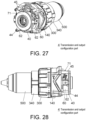
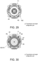
- FIGs. 5 to 20 relate to the structure of a transmission and output configuration part 4 (transmission and output unit) of the work machine 1. That is, FIGs. 5 to 20 relate to the structure of the portion in front of the motor 30.
- the transmission and output configuration part 4 includes a motor spacer 40 serving as a lid of the first case.
- the motor spacer 40 has a bearing holding part 41, a gear part 42, and four screw through holes 43.
- the bearing holding part 41 is positioned at the central rear of the motor spacer 40. As shown in FIG. 4 , the bearing holding part 41 holds a ball bearing 33 (bearing) that supports the front part of the motor shaft 31.
- the gear part 42 is provided on the inner peripheral surface of the motor spacer 40. In other words, the motor spacer 40 functions as a first-stage ring gear of the transmission mechanism 50.
- the four screw through holes 43 are through holes for passing screws 44 respectively.
- the screws 44 are fixing parts that secure the motor spacer 40 and a rear case 60 to a gear case 140.
- Two screws 44 on the upper side correspond to the first fixing part, and two screws 44 on the lower side correspond to the second fixing part.
- the screws 44 extend in the front-rear direction.
- Screw collars 45 appearing in FIGs. 6 to 7 are, for example, made of metal and are members through which the two screws 44 on the upper side pass.
- the transmission and output configuration part 4 includes the rear case 60 serving as a cylindrical case of the first case.
- the rear case 60 is, for example, made of resin.
- the rear case 60 has a tubular part 61, two screw boss parts 62 serving as through parts, a guide convex part 63, a guide hole 64, a spring holding hole 65, a flange part 66, and two through holes 67.
- the tubular part 61 is a cylindrical part coaxial with the motor shaft 31.
- the screw boss parts 62 are provided on the lower left and lower right parts of the tubular part 61, and protrude outward in the radial direction.
- the through holes 67 penetrate the screw boss parts 62 in the front-rear direction.
- the through holes 67 are portions through which the two screws 44 on the lower side as shown in FIGs. 6 and 7 pass.
- the guide convex part 63 functions as a rotation guide of the shift arm 71.
- the guide hole 64 is an elongated hole (groove-like hole) for passing through the shift arm 71, and serves as a guide for the front-rear movement of the lower part of the shift arm 71.
- the spring holding hole 65 opens on the front surface of the flange part 66 and is a non-through hole that holds the rear end of a stopper spring 117 appearing in FIGs. 5 to 7 .
- the flange part 66 extends outward in the radial direction from the front end of the tubular part 61.
- a left grease cover 68 and a right grease cover 69 appearing in FIGs. 6-7 are, for example, made of resin and are attached to the left and right sides of the tubular part 61 to cover the left and right guide holes 64, respectively.
- the left grease cover 68 and the right grease cover 69 function as spaces to collect lubricating oil that leaks from the respective guide holes 64.
- the transmission and output configuration part 4 includes a final ring gear 90.
- the final ring gear 90 is, for example, made of metal.
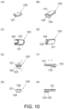
- the final ring gear 90 has six outer peripheral convex parts 91 (protrusion parts), a tubular part 92, a flange part 93, a gear part 94, six front surface convex parts 95, and six front surface concave parts 96.
- the tubular part 92 is a cylindrical part coaxial with the motor shaft 31.
- the flange part 93 extends outward in the radial direction from the front end of the tubular part 92.
- the six outer peripheral convex parts 91 are arranged at equal angular intervals in the peripheral direction, each protruding outward in the radial direction from the outer peripheral surface front part of the tubular part 92.
- the outer peripheral convex parts 91 are provided straddling the outer peripheral surface front parts of the tubular part 92 and the back surface of the flange part 93.
- the gear part 94 is provided on the inner peripheral surface of the tubular part 92.
- the front surface convex part 95 and the front surface concave part 96 are provided on the front surface of the flange part 93.
- the six front surface concave parts 96 are arranged at equal angular intervals in the peripheral direction.
- the front surface convex part 95 is positioned between adjacent front surface concave parts 96.
- the rear end of a clutch pin 131 which will be described later, is pressed against the front surface concave part 96.
- the transmission and output configuration part 4 includes a stopper block 120 as a stopper part.
- the stopper block 120 is, for example, made of metal.
- the stopper block 120 has a base part 121, a spring holding part 122, a locking convex part 123, and a wide protrusion part 124.
- the base part 121 is a surface part (plate-like part) that follows the inner peripheral surface of the gear case 140.
- the spring holding part 122 is a concave part provided on the back surface of the base part 121, and holds the front end of the stopper spring 117 that appears in FIGs. 5 to 7 .
- the base part 121 is positioned between the inner peripheral surface of the gear case 140 and the outer peripheral surface of the final ring gear 90.
- the locking convex part 123 is provided on a surface of the base part 121, which faces the outer peripheral surface of the final ring gear 90.
- the locking convex part 123 is a protrusion part that, when positioned at a lock position to be described later, engages with the outer peripheral convex part 91 of the final ring gear 90 to prevent the final ring gear 90 from rotating.
- the wide convex part 124 is connected to the rear of the locking convex part 123.
- the wide convex part 124 has a greater width in the peripheral direction than the locking convex part 123.
- the wide convex part 124 is provided to form the spring holding hole 122.
- the transmission and output configuration part 4 includes a gear case 140 as a second case.
- the gear case 140 is, for example, made of metal.
- the gear case 140 has a rear tubular part 141, a front wall part 142, six through holes 143, three rotation stopping parts 144, three through holes 145, a central through hole 146, four through holes 147, rotation stopping convex parts 148 and 149, a front tubular part 150, four screw holes 151, three stopper insertion grooves 152, and three stopper through holes 153.
- the rear tubular part 141 is a cylindrical part coaxial with the motor shaft 31 and formed a portion of the outer shell of the work machine 1.
- the front wall part 142 connects the front part of the rear tubular part 141 and the rear part of the front tubular part 150, and extends to the radially inner side of the front tubular part 150 in the radial direction.
- the six through holes 143 penetrate the front wall part 142 in the front-rear direction on the radially outer side of the front tubular part 150, and each holds a pin sleeve 161 (for example, made of metal) that appears in FIGs. 6 to 7 .
- the three rotation stopping parts 144 are arranged at equal angular intervals in the peripheral direction, and each protrudes forward from the front end of the front tubular part 150 and is bifurcated.
- the rotation stopping part 144 sandwiches the rotation stopping convex part 285 of a ratchet cam ring 280 to be described later, from both sides in the peripheral direction, preventing rotation of the ratchet cam ring 280.
- the rotation stopping convex parts 148 and 149 are protrusion parts that engage (fit) with rotation stopping concave parts 218 and 219 of the rear stopper cam ring 210, to be described later, to prevent rotation of a rear stopper cam ring 210.
- the front tubular part 150 is a cylindrical part coaxial with the motor shaft 31 and has a smaller diameter than the rear tubular part 141.
- the four screw holes 151 are portions where the screws 44 appearing in FIGs. 6 to 7 are screwed in.
- the three stopper insertion grooves 152 are provided in the peripheral direction at equal angular intervals on the inner peripheral surface of the rear tubular part 141, and each is a concave groove extending in the front-rear direction.
- the base part 121 of the stopper block 120 fits into each stopper insertion groove 152.
- the stopper block 120 can move in the front-rear direction by being guided by the stopper insertion groove 152.
- the three stopper through holes 153 each penetrate the front wall part 142 in the front-rear direction and communicate with the stopper insertion groove 152.
- the stopper block 120 can protrude forward from the front wall part 142 through each stopper through hole 153.
- the motor spacer 40, the rear case 60, and the gear case 140 are combined with each other by using four screws 44 and form a transmission part housing that accommodates the transmission mechanism 50.
- the transmission mechanism 50 is a deceleration mechanism formed by a planetary gear mechanism, and includes the gear part 42 of the motor spacer 40, a first planetary gear 51, a first carrier 55, a slide ring gear 57, a second planetary gear 81, a second carrier 85, a final planetary gear 87, a final ring gear 90, and a final carrier 101.
- the components forming the transmission mechanism 50 are, for example, made of metal.
- a needle bearing 53 appearing in FIGs. 6 to 7 is interposed between the inner peripheral surface of the first planetary gear 51 and the pin protruding rearward from the first carrier 55.
- the slide ring gear 57 has a groove part 58 engaged with the end of the shift arm 71.
- the slide ring gear 57 moves back and forth in accordance with the front-rear movement of the end of the shift arm 71 accompanying the rotation of the shift arm 71.
- the slide ring gear 57 when positioned at the front, meshes with the second planetary gear 81. At the time, the slide ring gear 57 is fixed to be non-rotatable by the shift dog 75 (for example, made of metal), and the transmission mechanism 50 achieves a high deceleration ratio with three-stage deceleration.
- the slide ring gear 57 when positioned at the rear, meshes with both the first planetary gear 51 and the second planetary gear 81. At the time, the transmission mechanism 50 achieves a low deceleration ratio with two-stage deceleration.
- a spline hub 105 appearing in FIGs. 5 to 7 is, for example, made of metal, and is a part that meshes with the inner peripheral part of the final carrier 101 and the rear-end outer peripheral part of the spindle 470 and transmits the rotation of the final carrier 101 to the spindle 470.
- the final carrier 101 is, for example, made of metal.
- a roller 103 and a lock ring 110 appearing in FIGs. 6 to 7 are, for example, made of metal, and are parts for suppressing the rotation transmission from the side of the spindle 470 and the chuck 500 to side of the final carrier 101.
- the roller 103 When attempting to rotate the chuck 500, the roller 103 is sandwiched and fixed between the outer peripheral part of the spline hub 105 and the inner peripheral part of the lock ring 110.
- the positional relationship of the respective components is such that the roller 103 is not fixed during the transmission of the rotation from the side of the final carrier 101 to the side of the spindle 470 and the chuck 500.
- the hub washer 115 appearing in FIGs. 6 to 7 is, for example, made of metal, interposed between the front surface of the spline hub 105 and the rear surface of the front wall part 142 of the gear case 140, avoids the contact between the gear case 140 and the spline hub 105, and reduces friction.
- the transmission and output configuration part 4 includes, as a first cam, the rear stopper cam ring 210.
- the rear stopper cam ring 210 is positioned on the front side of the stopper block 120, contacts the front end of the stopper block 120, and is biased toward the front side with respect to the stopper spring 117 via the stopper block 120. In addition, the rotation of the rear stopper cam ring 210 with respect to the gear case 140 is restricted.
- the rear stopper cam ring 210 includes a flat part 211, an outer peripheral inclination part 212, an outer peripheral flat part 213, an inner peripheral inclination part 214, an inner peripheral flat part 215, and rotation stopping concave parts 218, 219.
- the flat part 211 is a plane part perpendicular to the front-rear direction provided on the front surface of the rear stopper cam ring 210.
- the outer peripheral inclination part 212 is provided on the radially outer portion on the front surface of the rear stopper cam ring 210.
- the outer peripheral inclination part 212 is an inclined surface connected at an end to the flat part 211 and inclined from the flat part 211, so that the further the outer peripheral inclination part 212 goes to the right, the further the outer peripheral inclination part 212 progresses rearward.
- the outer peripheral flat part 213 is a plane part perpendicular to the front-rear direction extending in the peripheral direction from the other end of the outer peripheral inclination part 212.
- the outer peripheral inclination part 212 and the outer peripheral flat part 213 form a concave part or a hole part.
- the inner peripheral inclination part 214 is provided on the radially inner portion on the front surface of the rear stopper cam ring 210.
- the inner peripheral inclination part 214 is positioned substantially 180° apart from the outer peripheral inclination part 212 in the peripheral direction.
- the inner peripheral inclination part 214 is an inclined surface connected at an end to the flat part 21 and inclined from the flat part 211 so that the further inner peripheral inclination part 214 goes to the right, the further backward the inner peripheral inclination part 214 is inclined from the flat part 211.
- the inner peripheral flat part 215 is a plane part perpendicular to the front-rear direction extending in the peripheral direction from the other end of the inner peripheral inclination part 214.
- the inner peripheral inclination part 214 and the inner peripheral flat part 215 form a concave part or a hole part.
- the rotation stopping concave parts 218, 219 engage (fit) with the rotation stopping convex parts 148, 149 of the gear case 140, making the rear stopper cam ring 210 unable to rotate with respect to the gear case 140.
- the transmission and output configuration part 4 includes, as a second cam, a front stopper cam 0ring 230.
- the front stopper block 230 is, for example, made of metal.
- the front stopper cam ring 230 is positioned on the front side of the rear stopper cam ring 210 and rotates together with the clutch dial 300.
- the front stopper cam ring 230 includes an outer peripheral protrusion part 232, an inner peripheral protrusion part 234, and two locking protrusion parts 235.
- the outer peripheral protrusion part 232 protrudes rearward from the radially outer portion of the front stopper cam ring 230.
- the outer peripheral protrusion part 232 is a flat plate-like or curved plate-like part substantially perpendicular to the radial direction.
- the radial position of the outer peripheral protrusion part 232 is equal to the radial positions of the outer peripheral inclination part 212 and the outer peripheral flat part 213 of the rear stopper cam ring 210.
- the inner peripheral protrusion part 234 protrudes rearward from the radially inner portion of the front stopper cam ring 230.
- the inner peripheral protrusion part 234 is a flat plate-like or curved plate-like part substantially perpendicular to the radial direction.
- the inner peripheral protrusion part 234 is positioned substantially 180° apart from the outer peripheral protrusion part 232 in the peripheral direction.
- the radial position of the inner peripheral protrusion part 234 is equal to the radial positions of the inner peripheral inclination part 214 and the inner peripheral flat part 215 of the rear stopper cam ring 210.
- the two locking protrusion parts 235 protrude forward from the radially outer portion of the front stopper cam ring 230 at positions substantially 180° apart in the peripheral direction.
- the locking protrusion part 235 is a flat plate-like or curved plate-like part substantially perpendicular to the radial direction.
- the locking protrusion parts 235 engage (fit) with locking concave parts 302 of the clutch dial 300, which will be described later. As a result, the front stopper cam ring 230 rotates together with the clutch dial 300.
- the transmission and output configuration part 4 includes a nut 260 as a screw member.
- the nut 260 is, for example, made of resin.
- the nut 260 includes a screw part 261, six spring locking holes 262, and three notch parts 263.
- the screw part 261 is provided on the outer peripheral surface of the nut 260 and screwed into the screw part 301 of the clutch dial 300, which will be described later.
- the six spring locking holes 262 are non-through holes arranged at equal angular intervals in the peripheral direction, and each holds the front end of the clutch spring 250 (for example, made of metal) that appears in FIGs. 5 to 7 .
- the three notch parts 263 are arranged at equal angular intervals in the peripheral direction, and each allows the screw 133 that appears in FIGs. 5 to 7 to pass through.
- a thrust plate 165 that appears in FIGs. 6 to 7 is, for example, made of metal and biased rearward with respect to the nut 260 by the clutch spring 250, presses the front end of the clutch pin 131 rearward, and pushes the rear end of the clutch pin 131 against the front surface of the final ring gear 90.
- the clutch pin 131 for example, is made of metal, extends in the front-rear direction through the pin sleeve 161 held in the through hole 143 of the gear case 140.
- the transmission and output configuration part 4 includes the ratchet cam ring 280 as the cam ring.
- the ratchet cam ring 280 is, for example, made of metal.
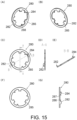
- the ratchet cam ring 280 includes an outer peripheral protrusion part 282, an inner peripheral protrusion part 284, three rotation stopping convex parts 285, and three fine protrusions 288.
- the outer peripheral protrusion part 282 protrudes forward from the radially outer portion of the ratchet cam ring 280.
- the outer peripheral protrusion part 282 is a flat plate-like or curved plate-like part substantially perpendicular to the radial direction.
- the inner peripheral protrusion part 284 protrudes forward from the radially inner portion of the ratchet cam ring 280.
- the inner peripheral protrusion part 284 is a flat plate-like or curved plate-like part substantially perpendicular to the radial direction.
- the three rotation stopping convex parts 285 are arranged at equal angular intervals in the peripheral direction, and each protrudes toward the center side of the ratchet cam ring 280.
- the rotation stopping convex part 285 is sandwiched in the gap of the bifurcated rotation stopping part 144 of the gear case 140. Accordingly, the ratchet cam ring 280 is unable to rotate relative to the gear case 140.
- the back surface of the rotation stopping convex part 285 is in contact with the front surface of the outer protrusion part 372 of the clutch hub 370, which will be described later, and pressed forward.
- the three fine protrusions 288 respectively protrude radially inward at a predetermined angle in the peripheral direction from the rotation stopping convex part 285.
- the fine protrusion 288 contacts the outer peripheral surface of a screw boss part 345 of the front case 340, which will be described later, at a position where the peripheral position of the rotation stopping convex part 285 coincides with the peripheral position of the outer protrusion part 372 of the clutch hub 370, and plays a role in positioning in the peripheral direction.
- the outer protrusion part 372 of the clutch hub 370 passes through the gap between the rotation stopping convex part 285 and the fine protrusion 288 in the peripheral direction. Then, the ratchet cam ring 280 is rotated until the fine protrusion 288 contacts the outer peripheral surface of the screw boss part 345 of the front case 340, and the back surface of the rotation stopping convex part 285 is brought into contact with the front surface of the outer protrusion part 372 of the clutch hub 370 by using the biasing force of the ratchet spring 360.
- the transmission and output configuration part 4 includes the clutch dial 300 as a switching operation part.
- the clutch dial 300 is, for example, made of resin.
- the clutch dial 300 includes a screw part 301, two locking concave parts 302, an inner peripheral concave part 304, an outer peripheral hole part 305, a tubular part 306, a front wall part 307, and a leaf spring installation part 308.
- the tubular part 306 has a center axis that is coaxial with the motor shaft 31, has a cross-section perpendicular to the front-rear direction in a substantially circular shape, and is in a shape that becomes smaller in diameter toward the front.
- the front wall part 307 extends radially inward from the front end of the tubular part 306.
- the screw part 301 is provided on the inner peripheral surface of the tubular part 306.
- the screw part 301 is screwed into the screw part 261 of the nut 260.
- the clutch dial 300 is sandwiched between the gear case 140 and the front case 340, which will be described later, in the front-rear direction to have a fixed position in the front-rear direction. As a result, the nut 260 moves in the front-rear direction in conjunction with the rotation of the clutch dial 300.
- the two locking concave parts 302 are positioned substantially 180° apart from each other in the peripheral direction, and are formed as notch parts where the lower end of the screw part 301 are respectively cut out partially.
- the locking concave parts 302 engage with the locking protrusion part 235 of the front stopper cam ring 230, causing the front stopper cam ring 230 to rotate together with the clutch dial 300.
- the inner peripheral concave part 304 is positioned on the radially inner portion of the back surface of the front wall part 307.
- the radial position of the inner peripheral concave part 304 is equal to the radial position of (or includes the radial position range of) the inner peripheral protrusion part 284 of the ratchet cam ring 280.
- the outer peripheral hole part 305 penetrates the radially outer portion of the front wall part 307 in the front-rear direction.
- the radial position of the outer peripheral hole part 305 is equal to the radial position of (or includes the radial position range of) the outer peripheral protrusion part 282 of the ratchet cam ring 280.
- the leaf spring installation part 308 is a part for attaching the leaf spring 331 (for example, made of metal) that appears in FIG. 6 to FIG. 7 .
- the transmission and output configuration part 4 includes the front case 340 as the output part housing.
- the front case 340 is, for example, made of metal.
- the front case 340 includes a large-diameter tubular part 341, a small-diameter tubular part 342, a connection surface part 343, three notch parts 344, three screw boss parts 345, three screw holes 346, three screw holes 347, a bearing holding part 348, two rotation stopping convex parts 349, two stopping convex parts 350, and a locking concave part 351.
- the large-diameter tubular part 341 is a cylindrical part coaxial with the motor shaft 31.
- the small-diameter tubular part 342 is a cylindrical part coaxial with the motor shaft 31.
- the small-diameter tubular part 342 has a diameter smaller than the large-diameter tubular part 341 and is positioned more rearward than the large-diameter tubular part 341.
- the ratchet spring 360, the rear ratchet 410, the front ratchet 440, and a ball bearing 461, etc. are disposed inside the small-diameter tubular part 342.
- the connection surface part 343 is a wall part perpendicular to the front-rear direction and connecting the rear end of the large-diameter tubular part 341 and the front end of the small-diameter tubular part 342.
- the three notch parts 344 are arranged at equal angular intervals in the peripheral direction, and each allows the outer protrusion part 372 of the clutch hub 370, which will be described later, to pass through.
- the three screw boss parts 345 are arranged at equal angular intervals in the peripheral direction, and are each provided in a shape that protrudes radially outward from the outer peripheral surface of the small-diameter tubular part 342.
- the three screw holes 347 are respectively non-through holes that open on the back surfaces of the screw boss parts 345, and each is screwed with the screw 133 that appears in FIG. 5 to FIG. 7 .
- the screw boss parts 345 and the screw holes 347 correspond to the output-part housing-side installation part.
- the three screw holes 346 are non-through holes open on the front surface of the connection surface part 343, and each is screwed with a screw 489 that appears in FIG. 5 to FIG. 7 .
- the three screw holes 346 are provided at the same positions in the peripheral direction as the three screw holes 347.
- the bearing holding part 348 holds the ball bearing 335 (bearing) that appears in FIG. 5 to FIG. 7 .
- the ball bearing 335 is, for example, made of metal and rotatably supports the rear part of the spindle 470.
- the two rotation stopping convex parts 349 are positioned substantially 180° apart from each other in the peripheral direction, and respectively protrude radially outward from the left and right parts of the outer peripheral surface of the large-diameter tubular part 341.
- the rotation stopping convex part 349 is a rotation restriction part that engages (fits) with the first rotation stopping concave part 616 or the second rotation stopping concave part 617 of a sub-handle 600 to be described later, and restricts the rotation of the sub-handle 600 relative to the front case 340.
- the two stopping convex parts 350 are positioned substantially 180° apart from each other in the peripheral direction, and respectively protrude radially outward from the left and right part of the outer peripheral surface of the large-diameter tubular part 341.
- the protrusion length of the stopping convex part 350 is shorter than the protrusion length of the rotation stopping convex part 349.
- the stopping convex part 350 extends in both sides of the peripheral direction from the rotation stopping convex part 349.
- the stopping convex part 350 prevents the sub-handle 600 to be described later from coming off (detaching) forward from the front case 340.
- the locking concave part 351 is a concave groove part into which the leaf spring 331 fits, and there are those corresponding to each level of the set tightening torque in the clutch mode, those corresponding to the drill mode, and those corresponding to the vibration mode.
- the transmission and output configuration part 4 includes the clutch hub 370.
- the clutch hub 370 is a restricting part that restricts the movement (rotation) of the rear ratchet 410 in the vibration mode.
- the clutch hub 370 is, for example, made of metal.
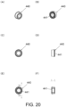
- the clutch hub 370 has an annular part 371, three outer protrusion parts 372, and six locking convex parts 373.
- the annular part 371 is a ring part coaxial with the motor shaft 31.
- the three outer protrusion parts 372 are arranged at equal angular intervals in the peripheral direction, and each protrudes radially outward from the outer peripheral surface of the annular part 371.
- the six locking convex parts 373 are arranged at equal angular intervals in the peripheral direction, and are protrusion parts each protruding radially inward from the rear part of the inner peripheral surface of the annular part 371.
- the transmission and output configuration part 4 includes a rear ratchet 410 as a second vibration part.
- the rear ratchet 410 is, for example, made of metal.
- the rear ratchet 410 is ring-shaped, has an concavo-convex part 411 on the front surface, and has six locking convex parts 412 on the front part of the outer peripheral surface.
- the six locking convex parts 412 are arranged at equal angular intervals in the peripheral direction, and are protrusion parts each protruding radially outward.
- the thrust bearing 391 and a bearing washer 395 appearing in FIG. 6 and FIG. 7 are, for example, made of metal, and are interposed between the back surface of the rear ratchet 410 and the opposing surface of the front case 340 and receive loads in the front-rear direction.
- the thrust bearing 391 and the bearing washer 395 reduce the friction and suppress the power loss when the tip tool 20 is used by being pressed against a workpiece.
- the transmission and output configuration part 4 includes the front ratchet 440 as a first vibration part.
- the front ratchet 440 is, for example, made of metal.
- the front ratchet 440 is ring-shaped and has, on the back surface, a concavo-convex part 441.
- the concavo-convex part 441 is a vibration generating shape part, which contacts the concavo-convex part 411 (vibration generating shape part) of the rear ratchet 410 and outputs the vibration to the spindle 470 by relative rotation.
- a spring 431 appearing in FIG. 5 to FIG. 7 is, for example, made of metal, and biases the front ratchet 440 forward with respect to the rear ratchet 410.
- the ratchet washer 435 is, for example, made of metal, avoids contact between the front ratchet 440 and the spring 431, and reduces friction.
- the ball bearing 461 appearing in FIG. 5 to FIG. 7 is, for example, made of metal, and rotatably supports the intermediate part of the front ratchet 440 and the spindle 470 with respect to the front case 340.
- the front ratchet 440 rotates integrally with the spindle 470.
- the transmission and output configuration part 4 includes the spindle 470 and the chuck 500. Both the spindle 470 and the chuck 500 are, for example, made of metal.
- the spindle 470 is rotationally driven by the motor 30 through the transmission mechanism 50.
- the chuck 500 holds the tip tool 20 appearing in FIG. 3 and rotates integrally with the spindle 470.
- the screw part on the rear inner peripheral surface of the chuck 500 is screwed onto the screw part on the front-portion outer peripheral surface of the spindle 470, thereby fixing the chuck 500 to the spindle 470. Additionally, the chuck 500 is fixed to the spindle 470 by a left screw 495 (for example, made of metal).
- the spindle 470 and the chuck 500 are firmly fixed to each other and form a tip tool holding part that is substantially integral.
- a bearing cover 485 appearing in FIG. 5 to FIG. 7 is, for example, made of metal, and is fixed to the front case 340 by the screw 489.
- the screw 489 passes through a through hole 487 of the bearing cover 485 and is screwed into the screw hole 346 of the front case 340.
- An O-ring 481 appearing in FIG. 5 to FIG. 7 is made of an elastic material such as rubber, and is provided between the inner peripheral surface of the bearing cover 485 and the outer peripheral surface of the spindle 470.
- the O-ring 481 slides on the inner peripheral surface of the bearing cover 485 and reduces the impact during rotation stop (braking).
- the O-ring 481 also has the function of preventing oil leakage.
- a stopping ring 483 appearing in FIG. 5 to FIG. 7 is, for example, made of metal, provided on the inner peripheral surface of the small-diameter tubular part 342 of the front case 340, and serves as a stopper for the ball bearing 461.
- FIG. 21 is a right cross-sectional view showing a state where the transmission and output configuration part 4 is separated into the transmission part 5, the output switching part 6, and the output part 7.
- the transmission part 5 is positioned in front of the motor 30 and transmits the driving force of the motor 30 to the spindle 470.
- the transmission part 5 includes a transmission part housing (the motor spacer 40, the rear case 60, the gear case 140) and various components (such as the transmission mechanism 50) held or supported by the transmission part housing.
- the output switching part 6 switches the output of the output part 7, namely the torque or the presence/absence of vibration.
- the output switching part 6 is positioned by being sandwiched between the output part 7 and the transmission part 5 in the front-rear direction.
- the output switching part 6 includes the clutch dial 300 and various components (such as the nut 260) held or supported by the clutch dial 300.
- the output part 7 includes the front case 340 and various components held or supported by the front case 340, namely the spindle 470, the chuck 500, the ball bearings 335, 461, and so on.
- the transmission part 5 is detachably assembled to the output part 7 from the rear side.
- the gear case 140 is assembled to the front case 340 from the rear side by the screw 133.
- the screw 133 passes through the through hole 145 of the gear case 140 and is screwed into the screw hole 347 of the front case 340.
- the screw 133 is an example of a fixing part that fixes the output part 7 and the transmission part 5.
- the ranges where the screw 133 and the output switching part 6 are present at least overlap partially.
- the work machine 1 has a clutch mode, a drill mode, and a vibration mode, and either of the modes can be selected by operating the clutch dial 300.
- the clutch mode is a mode in which the rotation transmission from the transmission mechanism 50 to the spindle 470 is interrupted when the set tightening torque (predetermined torque) is exceeded, that is, the clutch mode is a mode in which the clutch mechanism is effective.
- the set tightening torque can be adjusted in multiple stages, such as 22 stages, by operating the clutch dial 300.
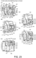
- FIGs. 23 indicate the state where the clutch mode is set and the set tightening torque is set to the lowest.
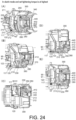
- (A) to (E) of FIGs. 24 indicate the state where the clutch mode is set and the set tightening torque is set to the highest.
- the clutch mechanism stops the rotation of the final ring gear 90 until the set tightening torque is reached, while allows the rotation of the final ring gear 90 when the torque becomes equal to or greater than the set tightening torque.
- the clutch mechanism includes the nut 260, the clutch spring 250, the thrust plate 165, and the clutch pin 131.
- the final ring gear 90 When the load (torque) is applied to the tip tool 20 during the driving of the motor 30, the final ring gear 90 that is not fixed attempts to rotate.
- the clutch pin 131 is positioned in the front surface concave part 96 of the final ring gear 90 until the set tightening torque is reached. As a result, the final ring gear 90 becomes unable to rotate, and the torque transmission by the transmission mechanism 50 becomes effective.
- the load (set tightening torque) when the clutch mechanism operates is proportional to the compression amount of the clutch spring 250.
- the nut 260 moves back and forth, and the compression amount of the clutch spring 250 is changed.
- the nut 260 In the state shown in (A) to (E) of FIG. 23 , the nut 260 is at the most advanced position, and the compression amount of the clutch spring 250 is at the minimum (the set tightening torque is at its lowest). From such state, as the nut 260 is rotated clockwise when viewed from the front, the nut 260 moves backward, and the compression amount of the clutch spring 250 increases. In the state shown in (A) to (E) of FIG. 24 , the nut 260 is in the most retracted position, and the compression amount of the clutch spring 250 is at the maximum (the set tightening torque is at the highest).
- the drill mode is a mode that makes the final ring gear 90 unable to rotate regardless of the clutch mechanism, and it is a mode in which the work machine 1 can output the maximum tightening torque.
- the structure for switching to the drill mode includes the stopper block 120, the stopper spring 117 as a biasing means, the rear stopper cam ring 210, and the front stopper cam ring 230.
- the stopper block 120 is movable between a lock position (forward position) and a non-lock position (retracted position), and makes the final ring gear 90 unable to rotate when at the lock position.
- the front end of the stopper block 120 protrudes further forward than the final ring gear 90.
- the stopper spring 117 made of metal, for example, biases the stopper block 120 forward, that is, toward the lock position.
- the clutch dial 300 is a switching operation part capable of switching the position of the stopper block 120 between the lock position and the non-lock position.
- the clutch dial 300 is positioned on the front side of the final ring gear 90.
- the clutch dial 300 is rotatable around the extension line of the axis of the motor shaft 31.
- the rear stopper cam ring 210 and the front stopper cam ring 230 are restricting parts that restrict the movement of the stopper block 120 from the non-lock position to the lock position by resisting the biasing of the stopper spring 117.
- the restriction and the release using the rear stopper cam ring 210 and the front stopper cam ring 230 are switched according to the operation of the clutch dial 300.
- the rear stopper cam ring 210 and the front stopper cam ring 230 form a cam mechanism that moves the stopper block 120 between the non-lock position and the lock position in conjunction with the rotation of the clutch dial 300.
- the rear stopper cam ring 210 is positioned on the front side of the stopper block 120, and the back surface of the rear stopper cam ring 210 contacts the stopper block 120.
- the rear stopper cam ring 210 contacts the stopper block 120 on the outer side of the final ring gear 90 in the radial direction of the final ring gear 90.
- the rear stopper cam ring 210 is positioned further forward than the final ring gear 90.
- the rear stopper cam ring 210 is biased forward with respect to the stopper spring 117 via the stopper block 120.
- the rotation of the rear stopper cam ring 210 relative to the gear case 140 is restricted by the engagement (fitting) of the rotation stopping convex part 148, 149 of the gear case 140 and the rotation stopping concave part 218, 219 of the rear stopper cam ring 210.
- the front stopper cam ring 230 is positioned on the front side of the rear stopper cam ring 210.
- the front stopper cam ring 230 rotates together with the clutch dial 300 due to the engagement (fitting) of the locking protrusion part 235 of the front stopper cam ring 230 with the locking concave part 302 of the clutch dial 300.
- the clutch dial 300 reaches the rotational position corresponding to the drill mode, that is, when the front stopper cam ring 230 reaches a predetermined rotational position, the rear stopper cam ring 210 moves forward. Accordingly, the movement restriction of the stopper block 120 from the non-lock position to the lock position is released.
- the rear stopper cam ring 210 has the outer peripheral inclination part 212 and the outer peripheral flat part 213 as concave parts, as well as the inner peripheral inclination part 214 and the inner peripheral flat part 215 as the concave part.
- the front stopper cam ring 230 has the outer peripheral protrusion part 232 and the inner peripheral protrusion part 234 as the convex part. In the process of the front stopper cam ring 230 reaching the predetermined rotational position (the process of the clutch dial 300 reaching the rotational position for drill mode), the outer peripheral protrusion part 232 and the inner peripheral protrusion part 234 lower the outer peripheral inclination part 212 and the inner peripheral inclination part 214, and the rear stopper cam ring 210 moves forward.
- the inclination of the outer peripheral inclination part 212 and the inner peripheral inclination part 214 may be steeper than the inclination of the screw part 301 of the clutch dial 300.
- FIG. 24 and (A) to (E) of FIG. 25 show the process of switching from the clutch mode to the drill mode, where the outer peripheral protrusion part 232 of the front stopper cam ring 230 lowers the outer peripheral inclination part 212 of the rear stopper cam ring 210, the rear stopper cam ring 210 advances due to the biasing of the stopper spring 117, and the stopper block 120 moves to the lock position (forward position).
- the locking convex part 123 of the stopper block 120 in the lock position engages (abuts in the rotational direction) with the outer peripheral convex part 91 of the final ring gear 90, making the final ring gear 90 unable to rotate.
- the locking convex part 123 of the stopper block 120 in the non-lock position does not engage with the outer peripheral convex part 91 of the final ring gear 90, and the final ring gear 90 is allowed to rotate.
- the clutch dial 300 When the clutch dial 300 is within a predetermined rotational range corresponding to the clutch mode (the rotational position between the state shown in (A) to (E) of FIG. 23 and the state shown in (A) to (E) of FIG. 24 ), the outer peripheral protrusion part 232 and the inner peripheral protrusion part 234 of the front stopper cam ring 230 abut against the flat part 211 of the rear stopper cam ring 210, the rear stopper cam ring 210 does not advance, and the stopper block 120 does not move to the lock position.
- the vibration mode is a mode that applies the vibration in the front-rear direction to the spindle 470 in the drill mode.
- the structure for switching to the drill mode includes the ratchet cam ring 280, the ratchet spring 360, the clutch hub 370, the rear ratchet 410, and the front ratchet 440.
- the rear ratchet 410 and the front ratchet 440 are vibration parts that output, as vibration, the driving force of the motor 30 to the spindle 470.
- the front ratchet 440 is driven (rotated) by the driving force of the motor 30.
- the clutch dial 300 switches between the vibration-on state and the vibration-off state of the rear ratchet 410 and the front ratchet 440.
- the ratchet cam ring 280 and the clutch hub 370 are vibration switching parts that move from a vibration-off position (retracted position) to a vibration-on position (advanced position) in response to the operation of the clutch dial 300.
- the ratchet spring 360 which is made of metal for example, is a biasing part that biases the ratchet cam ring 280 and the clutch hub 370 forward, that is, toward the vibration-on position.
- the outer peripheral protrusion part 282 and the inner peripheral protrusion part 284 of the ratchet cam ring 280 appearing in (A) to (E) and (G) of FIG. 15 and the inner peripheral concave part 304 and the outer peripheral hole part 305 of the clutch dial 300 appearing in (A) to (C) and (E) of FIG. 16 are guide parts that guide the ratchet cam ring 280 and the clutch hub 370 to move from the vibration-off position to the vibration-on position when the clutch dial 300 comes to the rotational position corresponding to the vibration mode.
- the outer peripheral protrusion part 282 of the ratchet cam ring 280 faces the outer peripheral hole part 305 of the clutch dial 300, and the inner peripheral protrusion part 284 of the ratchet cam ring 280 faces the inner peripheral concave part 304 of the clutch dial 300. Then, with the outer peripheral protrusion part 282 and inner peripheral protrusion part 284 of the ratchet cam ring 280 entering into the outer peripheral hole part 305 and the inner peripheral concave part 304 of the clutch dial 300 respectively, the ratchet cam ring 280 and the clutch hub 370 move from the vibration-off position to the vibration-on position due to the biasing of the ratchet spring 360.
- the inclination parts 286, 287 appearing in (G) of FIG. 15 which are provided at a peripheral end of the outer peripheral protrusion part 282 and the inner peripheral protrusion part 284 of the ratchet cam ring 280, respectively, serve to smoothen the entry and exit of the outer peripheral protrusion part 282 and the inner peripheral protrusion part 284 into and out of the outer peripheral hole part 305 and the inner peripheral concave part 304 of the clutch dial 300.
- the clutch hub 370 in the vibration-off position, does not restrict the movement of the rear ratchet 410, and, in the vibration-on position, restricts the movement of the rear ratchet 410. Vibration is generated by driving the front ratchet 440 by using the driving force of the motor 30 with respect to the rear ratchet 410 whose movement is restricted.
- the clutch hub 370 is biased forward by the ratchet spring 360 and presses the ratchet cam ring 280 forward.
- inclination parts 374, 413 are provided on two side parts of the locking convex part 373 of the clutch hub 370 and the locking convex part 412 of the rear ratchet 410 in the peripheral direction, making it difficult for the clutch hub 370 to move from the vibration-on position to the vibration-off position.
- the inclination angle is represented as ⁇ /2 with respect to the front-rear direction.
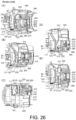
- FIG. 25 and (A) to (E) of FIG. 26 show the process of switching from the drill mode to the vibration mode, where the ratchet cam ring 280 and the clutch hub 370 advance through the biasing of the ratchet spring 360, and the positions of the locking convex part 373 of the clutch hub 370 and the locking convex part 412 of the rear ratchet 410 in the front-rear direction are aligned.
- the outer peripheral protrusion part 282 and the inner peripheral protrusion part 284 of the ratchet cam ring 280 are in contact with the flat part (the plane part perpendicular to the front-rear direction) of the clutch dial 300, and the ratchet cam ring 280 and clutch hub 370 do not advance (do not move to the vibration-on position).
- the shift arm 71 extends to the guide hole 64 of the rear case 60 by passing through the inner side of the screw 44 in the radial direction of the rear case 60.
- the two screws 44 on the upper side have portions extending the outer side of the rear case 60 in the front-rear direction.
- the portions are inserted through screw collars 45, which are tubular parts separate from the rear case 60.
- screw collars 45 are tubular parts separate from the rear case 60.
- each of the two screws 44 on the upper side penetrates through the screw through hole 43 of the motor spacer 40 and the screw collar 45, and is screwed into the screw hole 151 of the gear case 140.
- the screw collar 45 is used to suppress the motor spacer 40 from being bent or broken due to over-tightening of the two screws 44 on the upper side.
- the shift arm 71 passes through the gap between the outer peripheral surface of the screw collar 45 and the outer peripheral surface of the rear case 60.
- Each of the two screws 44 on the lower side penetrates through the screw through hole 43 of the motor spacer 40 and the through hole 67 of the rear case 60, and is screwed into the screw hole 151 of the gear case 140.
- the screw boss part 62 having the through hole 67 is a part of the rear case 60 (integral with the rear case 60), and there is no gap between the screw boss part 62 and the outer surface of the rear case 60. However, this is not the part where the shift arm 71 passes through, so there are no issues such as an increased size.
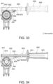
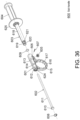
- FIGs. 31 to 39 relate to the sub-handle 600 of the embodiment.
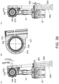
- FIGs. 31 to 34 and FIG. 39 show the work machine 1 with the sub-handle 600 attached.
- FIGs. 35 to 38 show the sub-handle 600 alone.
- the front case 340 is a handle installation part of the work machine 1. It should be noted that the sub-handle 600 is not limited to the mounting structure extending leftward from the work machine 1 as shown in FIG. 31 , etc., but can also be mounted in a structure extending rightward from the work machine 1.
- the sub-handle 600 includes a mounting part 601, a first shaft part 602, and a second shaft part 603.
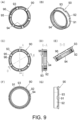
- the mounting part 601 is annular with a gap 614 in a portion in the peripheral direction, and engages with the front case 340 of the work machine 1.
- the mounting part 601 has a pin through hole 606, a first tubular part 612, a second tubular part 613, and an annular part 615.
- the first tubular part 612 is provided on the upper part of the annular part 615 and on a side (the left side in FIG. 35 ) of the gap 614 in the length direction of the gap 614 (hereinafter referred to as "gap length direction"), and extends in the gap length direction.
- the first tubular part 612 has a head holding part 624 and a shaft insertion part 626.
- the head holding part 624 holds a head part 610 of the first shaft part 602.
- the head holding part 624 is positioned on a side (the left side in FIG. 35 ) of the shaft insertion part 626 in the gap length direction, and when viewed from the gap length direction, the head holding part 624 is larger than the shaft insertion part 626 and non-circular, such as being hexagonal, and the head part 610 fits into the head holding part 624.
- the shaft insertion part 626 when viewed from the gap length direction, is smaller than the head part 610 and allows the shaft part 611 of the first shaft part 602 to pass through.
- the second tubular part 613 is provided on the upper part of the annular part 615 and on the other side (the right side in FIG. 35 ) of the gap 614 in the gap length direction, and extends in the gap length direction.
- the center axes of the first tubular part 612 and the second tubular part 613 are parallel to the gap length direction.
- the second tubular part 613 has a shaft insertion part 627 and an extended diameter part 628.
- the shaft insertion part 627 allows the shaft part 611 of the first shaft part 602 to pass through.
- the extended diameter part 628 is positioned on the other side (the right side in FIG. 35 ) of the shaft insertion part 627 in the gap length direction, has a larger diameter than the shaft insertion part 627, and allows the shaft part 611 of the first shaft part 602 to pass through while also allowing the end of the second shaft part 603 to be inserted.
- the pin through hole 606 faces the interior of the extended diameter part 628.
- the pin through hole 606 opens in a direction that intersects with the gap length direction.
- the annular part 615 has, on the inner peripheral surface, two first rotation stopping concave parts 616 and ten second rotation stopping concave parts 617.
- the two first rotation stopping concave parts 616 are provided substantially 180° apart in the peripheral direction of the mounting part 601.
- the two first rotation stopping concave parts 616 are mutually opposed to each other by sandwiching the center part of the mounting part 601.
- the ten second rotation stopping concave parts 617 are provided at equal angular intervals, and each five of the second rotation stopping concave parts 617 are provided between the two first rotation stopping concave parts 616 in the peripheral direction of the mounting part 601.
- the first rotation stopping concave part 616 is longer in the peripheral direction of the mounting part 601 than the second rotation stopping concave part 617.
- a depth gauge (not shown) can be mounted to the sub-handle 600, and a knob bolt 605 is used to secure the depth gauge.
- the first shaft part 602 and the second shaft part 603 form an adjustment mechanism that can adjust the length of the gap 614 within a predetermined range including a length greater than the natural length.
- the natural length is a length of the gap 614 in a state where no external force is applied to the mounting part 601 to widen or narrow the gap 614.
- the first shaft part 602 extends in the gap length direction and is unmovably provided on the mounting part 601 on a side (the left side in FIG. 35 ) of the gap 614 in the gap length direction.
- the first shaft part 602 passes through the gap 614 and protrudes from the mounting part 601 toward the other side in the gap length direction.
- the second shaft part 603 extends in the gap length direction and is unmovably provided on the mounting part 601 on the other side (the right side in FIG. 35 ) of the gap 614 in the gap length direction.
- the second shaft part 603 protrudes from the mounting part 601 toward the other side in the length direction.
- the first shaft part 602 and the second shaft part 603 are engaged to be movable in the gap length direction, and the length of the gap 614 is adjustable by moving the second shaft part 603 relative to the first shaft part 602 in the gap length direction.
- the first and second shaft parts 603 are screw-engaged with each other, and by rotating the second shaft part 603 relative to the first shaft part 602, the second shaft part 603 is movable relative to the first shaft part 602 in the length direction.
- the first shaft part 602 includes a head part 610 and a shaft part 611.
- the head part 610 is positioned on a side of the shaft part 611 in the gap length direction and, when viewed from the gap length direction, the head part 610 is larger in size than the shaft part 611 and non-circular, such as being hexagonal.
- the head part 610 fits into the head holding part 624 of the mounting part 601, thereby making the first shaft part 602 not rotatable relative to the mounting part 601 and preventing the first shaft part 602 from coming out of the mounting part 601 on the other side (the right side in FIG. 35 ) in the gap length direction.
- the shaft part 611 extends from the head part 610 to the other side in the gap length direction, passes through the shaft through parts 626, 627 of the mounting part 601, and reaches the inner side of the second shaft part 603.
- a male screw part 622 is provided on the outer peripheral surface of the tip end of the shaft part 611.
- the second shaft part 603 includes, in the order from the other side in the gap length direction, a grip part 604, a large-diameter part 618, and a small-diameter part 619.
- the small-diameter part 619 is inserted into the extended diameter part 628 of the second tubular part 613 of the mounting part 601. Both the small-diameter part 619 and the extended diameter part 628 have circular cross-sections.
- the small-diameter part 619 includes a pin through groove 620 and an O-ring fitting groove 621.
- the pin through groove 620 and the O-ring fitting groove 621 are groove parts that each encircle the outer peripheral part of the small-diameter part 619.
- the pin through groove 620 is positioned on a side (the left side in FIG. 35 ) of the O-ring fitting groove 621 in the gap length direction.
- the pin 607 inserted into the pin through hole 606 extends into the pin through groove 620.
- the pin through hole 606 is positioned at the same position as the pin through groove 620 in the gap length direction.
- the pin 607 passes through the pin through hole 606 and extends into the interior of the pin through groove 620, and prevents the second shaft part 603 from moving in the gap length direction relative to the second tubular part 613 of the mounting part 601.
- the second shaft part 603 is rotatable relative to the second tubular part 613.
- An O-ring 609 fits into the O-ring fitting groove 621.
- the O-ring 609 generates frictional resistance against the rotation of the second shaft part 603 relative to the second tubular part 613, and suppresses the second shaft part 603 from rotating easily.
- the second shaft part 603 includes a nut part 623 that forms a female screw part.
- the nut part 623 is screwed into the male screw part 622 of the first shaft part 602.
- the nut part 623 may be a separate component from or integrated with the large-diameter part 618 and the small-diameter part 619. In the example of FIG. 35 , the nut part 623 is shown as a separate component from the large-diameter part 618 and the small-diameter part 619.
- the entire second shaft part 603 integrally rotates relative to the mounting part 601 and the first shaft part 602.
- the second shaft part 603 moves in the gap length direction relative to the first shaft part 602.
- the second tubular part 613 moves in the gap length direction relative to the first tubular part 612. This adjusts the length of the gap 614.
- the length of the screw engagement between the male screw part 622 of the first shaft part 602 and the nut 623 of the second shaft part 603 is set such that the upper limit of the length of the gap 614 is within a predetermined length that does not damage the mounting part 601.
- the stopping convex part 350 of the front case 340 has dimensions that are too large to be inserted into the inner side of the mounting part 601 in the state where the gap 614 is the natural length.
- the stopping convex part 350 suppresses (prevents) the mounting part 601 from coming off forward from the front case 340 in the state where the gap 614 is at the natural length or shorter than the natural length.
- the mounting part 601 is fitted onto the front case 340 from the front side in the state where the length of the gap 614 is adjusted to be longer than the natural length. Then, the grip part 604 is rotated to the right to reduce the gap 614.
- the attachment angle can be selected from multiple stages.
- two corresponding to the attachment angle of the sub-handle 600 relative to the front case 340 are in concavo-convex engagement with the two rotation stopping convex parts 349 of the front case 340.
- the length of the first rotation stopping concave part 616 of the mounting part 601 in the peripheral direction is longer than the length of the rotation stopping convex part 349 of the front case 340 in the peripheral direction.
- the length of the second rotation stopping concave part 617 of the mounting part 601 in the peripheral direction is substantially equal to the length of the rotation stopping convex part 349 of the front case 340 in the peripheral direction.
- the sub-handle 600 can be mounted to the front case 340 with no or minimal rattling.
- the second rotation stopping concave part 617 of the mounting part 601 is used in the non-storage state of the sub-handle 600, that is, when the work machine 1 is in use.
- the sub-handle 600 is able to rotate within a predetermined angular range relative to the front case 340.
- the first rotation stopping concave part 616 is used in the storage state of the sub-handle 600, that is, when the work machine 1 is not in use.
- FIG. 39 are diagrams showing that the sub-handle 600 is rotatable within a predetermined angular range in an accommodated state.
- FIG. 39 shows the state where the sub-handle 600 is rotated counterclockwise to its maximum extent in the figure.
- Such state is a first engagement state where an end-side end of the first rotation stopping concave part 616 of the mounting part 601 engages with an end-side end of the rotation stopping convex part 349 of the front case 340 in the peripheral direction.
- FIG. 39 shows the state where the sub-handle 600 is in the center of its rotatable range.
- Such state is a second engagement state where the end-side end of the first rotation stopping concave part 616 of the mounting part 601 does not contact the end-side end of the rotation stopping convex part 349 of the front case 340 in the peripheral direction.
- the other end-side end of the first rotation stopping concave part 616 of the mounting part 601 may engage with the other end side end of the rotation stopping convex part 349 of the front case 340 in the peripheral direction.
- the sub-handle 600 becomes unable to rotate relative to the front case 340 due to the frictional force caused by the mounting part 601 tightening the front case 340.
- the embodiment provides the following operational effects.
- the concavo-convex structure exemplified in the embodiment may have the relationship between the concave part and the convex part appropriately reversed.
- the structure may be configured such that the rear stopper cam ring 210 includes a convex part, and the front stopper cam ring 230 includes a concave part that engages with the convex part.
- the structure may be configured such that the ratchet cam ring 280 includes a concave part, and the clutch dial 300 includes a convex part that engages with the concave part.
- the specific numbers exemplified in the embodiment such as the number of the outer peripheral convex parts 91 of the final ring gear 90, the number of the stopper blocks 120, the number of the screws 44 and 133, the number of the stages of set tightening torque, the number of the types of attachment angles of the sub-handle 600 to the work machine 1, and the number of the first rotation stopping concave parts 616 and the second rotation stopping concave parts 617, do not in any way limit the scope of the invention and can be arbitrarily changed according to the required specifications.
Landscapes
- Engineering & Computer Science (AREA)
- Mechanical Engineering (AREA)
- Portable Power Tools In General (AREA)
- Mechanical Operated Clutches (AREA)
- Connection Of Motors, Electrical Generators, Mechanical Devices, And The Like (AREA)
Abstract
Description
- The invention relates to a work machine.
-
Patent Documents 1 and 2 disclose work machines such as driver drills. Patent Document 3 discloses a work machine with a detachable handle. - The work machine such as a driver drill includes a motor, a spindle, a transmission mechanism that transmits the rotation of the motor to the spindle, a chuck screwed to the spindle, a deceleration ratio switching mechanism that switches the deceleration ratio of the transmission mechanism, and a clutch mechanism that interrupts, at a predetermined torque, the rotation transmission from the transmission mechanism to the spindle.
- The deceleration ratio switching mechanism has a shift knob operated by the user and a shift arm for advancing and retracting a slide ring gear of a transmission mechanism in conjunction with the operation of the shift knob. A clutch mechanism has a clutch dial for the user to change a predetermined torque. A driver drill with a vibration function, such as the one in Patent Document 2, is also referred to as a vibration driver drill, and the presence or absence of vibration can also be switched by operating the clutch dial.
-
- Patent Document 1:
Japanese Laid-open Publication No. 2014-018914 - Patent Document 2:
Japanese Laid-open Publication No. 2015-191735 - Patent Document 3:
Japanese Laid-open Publication No. 2017-80853 - In a work machine such as a driver drill, a chuck and a spindle are fixed with high torque, and a special jig is required to release the fixation. In other words, without the special jig, the chuck and the spindle substantially serve as an integral tip tool holding part. Therefore, it is difficult to replace parts that cannot be removed without releasing the fixation of the chuck and spindle. A conventional work machine has many parts that are difficult to replace, resulting in poor repairability. The first issue recognized by the inventor of the invention is to provide a work machine with good repairability.
- In a work machine such as a driver drill, the drill mode with maximum torque is set by fixing a ring gear of the transmission mechanism to be not rotatable. As a structure for setting the drill mode, a structure is formed in which a nut that rotates with a clutch dial and moves axially pushes a stopper pin toward the ring gear side. Here, depending on the rotational position of the ring gear, a portion of the ring gear may be present in the extension of the stopper pin. In such structure, if the stopper pin abuts against the portion, the clutch dial becomes unable to rotate, making it not possible to transition to the drill mode. As a result, the usability is poor. The second issue recognized by the inventor of the invention is to provide a work machine that can suppress the malfunction of being unable to make the ring gear non-rotatable.
- In a work machine such as a driver drill, in the case of a structure where a transmission mechanism is accommodated in multiple cases divided in the front-rear direction, by fixing the cases in the front-rear direction by using a fixing part such as a screw, the rigidity of the cases can be increased and deformation can be suppressed by fixing multiple cases. In a structure in which a shift arm passes the outer side of the fixing part in the radial direction of the case, the size of the product increases in the radial direction. The third issue recognized by the inventor of the invention is to provide a work machine that can prevent the size from increasing.
- In the work machine such as a vibration driver drill, when the operation amount required for the clutch dial to switch between vibration and non-vibration modes is large, it takes more effort to switch between vibration and non-vibration, resulting in poor workability. The fourth issue recognized by the inventor of the invention is to provide a work machine that can reduce the effort required to switch between vibration and non-vibration.
- As a structure in which a handle is detachable to a work machine, a structure is known where an annular mounting part is provided with a gap (opening) in a portion in the peripheral direction is attached to the work machine in a way that closes the gap. In the structure, when the maximum length of the gap in the mounting part is the natural length, it may be difficult to attach or detach the handle. The fifth issue recognized by the inventor of the invention is to provide a handle that can be easily attached to and detached from the work machine, and a work machine provided with a handle that can be easily attached and detached.
- When the handle is not movable in a state of being mounted to the work machine, it may be inconvenient as fine adjustment to the mounting state cannot be made. The sixth issue recognized by the inventor of the invention is to provide a handle that allows fine adjustment to the mounting state of the work machine, and a work machine provided with a handle that allows fine adjustment in the mounting state.
- An objective of the invention is to provide a work machine that at least solves the first issue among the above issues.
- An aspect of the invention provides a work machine. The work machine includes: an output part, having a tip tool holding part, and a bearing part supporting the tip tool holding part, the output part being positioned on one side of the motor in an axial direction of the motor; a transmission part, configured as a transmission part that transmits a driving force of the motor to the tip tool holding part, and detachably assembled to the output part from an other side in the axial direction to be positioned on the one side of the motor in the axial direction; and an output switching part, configured as an output switching part that switches an output of the output part, and disposed by being sandwiched between the output part and the transmission part. When the transmission part is removed from the output part, the output switching part is able to be removed from the output part toward the other side in the axial direction
- The invention may also be expressed as "electric work machine", "electric tool", or "electric device ", and such expressions are also valid as aspects of the invention.
- According to the invention, a work machine having solved at least the first issues among the above issues can be provided.
-
- [
FIG. 1] FIG. 1 is a perspective view of awork machine 1 according to an embodiment of the invention, as seen from the front side. - [
FIG. 2] FIG. 2 is a perspective view of thework machine 1 as seen from the rear side. - [
FIG. 3] FIG. 3 is a right side view of thework machine 1. - [
FIG. 4] FIG. 4 a right side cross-sectional view of thework machine 1. - [
FIG. 5] FIG. 5 is an enlarged right side cross-sectional view showing the structure of a transmission andoutput configuration part 4 of thework machine 1. - [
FIG. 6] FIG. 6 is an exploded perspective view of the transmission andoutput configuration part 4, and is a perspective view seen from the front side. - [
FIG. 7] FIG. 7 is an exploded perspective view of the transmission andoutput configuration part 4, and is a perspective view seen from the rear side. - [
FIG. 8 ] (A) ofFIG. 8 is a perspective view of arear case 60 appearing inFIGs. 5 to 7 , as seen from the front side, (B) ofFIG. 8 is a perspective view of therear case 60 as seen from the rear side, (C) ofFIG. 8 is a front view of therear case 60, (D) ofFIG. 8 is a cross-sectional view along line A-A in (C) ofFIG. 8, (E) ofFIG. 8 is a cross-sectional view along line B-B in (C) ofFIG. 8, (F) ofFIG. 8 is a rear view of therear case 60, and (G) ofFIG. 8 is a right side view of therear case 60. - [
FIG. 9 ] (A) ofFIG. 9 is a perspective view of afinal ring gear 90 appearing inFIGs. 5 to 7 , as seen from the front side, (B) ofFIG. 9 is a perspective view of thefinal ring gear 90 as seen from the rear side, (C) ofFIG. 9 is a front view of thefinal ring gear 90, (D) ofFIG. 9 is a cross-sectional view along line A-A in (C) ofFIG. 9, (E) ofFIG. 9 is a cross-sectional view along line B-B in (C) ofFIG. 9, (F) ofFIG. 9 is a rear view of thefinal ring gear 90, and (G) ofFIG. 9 is a right side view of thefinal ring gear 90. - [
FIG. 10 ] (A) to (D) ofFIG. 10 are perspective views of astopper block 120 appearing inFIGs. 5 to 7 , as seen from different viewpoints, (E) ofFIG. 10 is a front view of thestopper block 120, (F) ofFIG. 10 is a cross-sectional view along line A-A in (E) ofFIG. 10, (G) ofFIG. 10 is a rear view of thestopper block 120, and (G) ofFIG. 10 is a right side view of thestopper block 120. - [
FIG. 11 ] (A) ofFIG. 11 is a perspective view of agear case 140 appearing inFIGs. 5 to 7 ,(B) ofFIG. 11 is a front view of thegear case 140, (C) ofFIG. 11 is a cross-sectional view along line A-A in (B) ofFIG. 11, (D) ofFIG. 11 is a rear view of thegear case 140, and (E) ofFIG. 11 is a right side view of thegear case 140. - [
FIG. 12 ] (A) ofFIG. 12 is a perspective view of a rearstopper cam ring 210 appearing inFIGs. 5 to 7 , as seen from the front side, (B) ofFIG. 12 is a perspective view of the rearstopper cam ring 210, as seen from the rear side, (C) ofFIG. 12 is a perspective view of the rearstopper cam ring 210 as seen from the rear side, (D) ofFIG. 12 is a cross-sectional view along line A-A in (C) ofFIG. 12, (E) ofFIG. 12 is a cross-sectional view along line B-B in (C) ofFIG. 12, (F) ofFIG. 12 is a rear view of the rearstopper cam ring 210, and (G) ofFIG. 12 is a right side view of the rearstopper cam ring 210. - [
FIG. 13 ] (A) ofFIG. 13 is a perspective view of a frontstopper cam ring 230 appearing inFIGs. 5 to 7 , as seen from the front side, (B) ofFIG. 13 is a perspective view of the frontstopper cam ring 230, as seen from the rear side, (C) ofFIG. 13 is a perspective view of the frontstopper cam ring 230 as seen from the rear side, (D) ofFIG. 13 is a cross-sectional view along line A-A in (C) ofFIG. 13, (E) ofFIG. 13 is a cross-sectional view along line B-B in (C) ofFIG. 13, (F) ofFIG. 13 is a rear view of the frontstopper cam ring 230, and (G) ofFIG. 13 is a right side view of the frontstopper cam ring 230. - [
FIG. 14 ] (A) ofFIG. 14 is a perspective view of anut 260 appearing inFIGs. 5 to 7 ,(B) ofFIG. 14 is a front view of thenut 260, (C) ofFIG. 14 is a cross-sectional view along line A-A in (B) ofFIG. 14, (D) ofFIG. 14 is a rear view of thenut 260, and (E) ofFIG. 14 is a right side view of thenut 260. - [
FIG. 15 ] (A) ofFIG. 15 is a perspective view of aratchet cam ring 280 appearing inFIGs. 5 to 7 , as seen from the front side, (B) ofFIG. 15 is a perspective view of theratchet cam ring 280, as seen from the rear side, (C) ofFIG. 15 is a front view of theratchet cam ring 280, (D) ofFIG. 15 is a cross-sectional view along line A-A in (C) ofFIG. 15, (E) ofFIG. 15 is a cross-sectional view along line B-B in (C) ofFIG. 15, (F) ofFIG. 15 is a rear view of theratchet cam ring 280, and (G) ofFIG. 15 is a right side view of theratchet cam ring 280. - [
FIG. 16 ] (A) ofFIG. 16 is a perspective view of aclutch dial 300 appearing inFIGs. 5 to 7 , as seen from the front side. (B) ofFIG. 16 is a perspective view of theclutch dial 300 as seen from the rear side, (C) ofFIG. 16 is a front view of theclutch dial 300, (D) ofFIG. 16 is a cross-sectional view along line A-A in (C) ofFIG. 16, (E) ofFIG. 16 is a rear view of theclutch dial 300, (F) ofFIG. 16 is a right side view of theclutch dial 300. - [
FIG. 17 ] (A) ofFIG. 17 is a perspective view of afront case 340 appearing inFIGs. 5 to 7 ,(B) ofFIG. 17 is a front view of thefront case 340, (C) ofFIG. 17 is a cross-sectional view along line A-A in (B) ofFIG. 17, (D) ofFIG. 17 is a rear view of thefront case 340, and (E) ofFIG. 17 is a right side view of thefront case 340. - [
FIG. 18 ] (A) ofFIG. 18 is a perspective view of aclutch hub 370 appearing inFIGs. 5 to 7 ,(B) ofFIG. 18 is a front view of theclutch hub 370, (C) ofFIG. 18 is a cross-sectional view along line A-A in (C) ofFIG. 18, (D) ofFIG. 18 is a rear view of theclutch hub 370, and (E) ofFIG. 18 is a right side view of theclutch hub 370. - [
FIG. 19 ] (A) ofFIG. 19 is a perspective view of arear ratchet 410 appearing inFIGs. 5 to 7 , as seen from the front side, (B) ofFIG. 19 is a perspective view of therear ratchet 410 as seen from the rear side, (C) ofFIG. 19 is a front view of therear ratchet 410, (D) ofFIG. 19 is a cross-sectional view along line A-A in (C) ofFIG. 19, (E) ofFIG. 19 is a rear view of therear ratchet 410, and (F) ofFIG. 19 is a right side view of therear ratchet 410. - [
FIG. 20 ] (A) ofFIG. 20 is a perspective view of afront ratchet 440 appearing inFIGs. 5 to 7 , as seen from the front side, (B) ofFIG. 20 is a perspective view of thefront ratchet 440 as seen from the rear side, (C) ofFIG. 20 is a front view of thefront ratchet 440, (D) ofFIG. 20 is a left side view of thefront ratchet 440, and (E) ofFIG. 20 is a rear view of thefront ratchet 440, and (F) ofFIG. 20 is a cross-sectional view along line A-A in (E) ofFIG. 20 . - [
FIG. 21] FIG. 21 is a right cross-sectional view showing a state where the transmission andoutput configuration part 4 is separated into atransmission part 5, anoutput switching part 6, and anoutput part 7. - [
FIG. 22 ] (A) ofFIG. 22 is a view of theclutch hub 370 and therear ratchet 410 as seen from the front, (B) ofFIG. 22 is a cross-sectional view along line A-A in (A) ofFIG. 22 , and shows a positional relationship between a lockingconvex part 373 of theclutch hub 370 and a lockingconvex part 412 of therear ratchet 410 in a mode other than a vibration mode, (C) ofFIG. 22 is a cross-sectional view along line A-A in (A) ofFIG. 22 , and shows a positional relationship between the lockingconvex part 373 of theclutch hub 370 and the lockingconvex part 412 of therear ratchet 410 in the vibration mode. This is an engagement explanation diagram. - [
FIG. 23 ] (A) to (E) ofFIG. 23 are views illustrating configurations in which a portion is cut off, and are views showing necessary structures of the work machine in which a clutch mode and a set tightening torque are set to the lowest from respectively different viewpoints. - [
FIG. 24 ] (A) to (E) ofFIG. 24 are views illustrating configurations in which a portion is cut off, and are views showing necessary structures of the work machine in which a clutch mode and a set tightening torque are set to the highest from respectively different viewpoints. - [
FIG. 25 ] (A) to (E) ofFIG. 25 are views illustrating configurations in which a portion is cut off, and are views showing necessary structures of the work machine set to a drill mode from respectively different viewpoints. - [
FIG. 26 ] (A) to (E) ofFIG. 26 are views illustrating configurations in which a portion is cut off, and are views showing necessary structures of the work machine set to a vibration mode from respectively different viewpoints. - [
FIG. 27] FIG. 27 is a perspective view of the transmission andoutput configuration part 4 as seen from the rear. - [
FIG. 28] FIG. 28 is a left side view of the transmission andoutput configuration part 4. - [
FIG. 29] FIG. 29 is a rear view of the transmission andoutput configuration part 4. - [
FIG. 30] FIG. 30 is a rear cross-sectional view of the transmission andoutput configuration part 4, and is a cross-sectional view cut at an engagement portion between ashift arm 71 and aslide ring gear 57. - [
FIG. 31] FIG. 31 is a perspective view of an upper part of thework machine 1 to which a sub-handle 600 is mounted, as seen from the front. - [
FIG. 32] FIG. 32 is a perspective view of the upper part of thework machine 1 to which the sub-handle 600 is mounted, as seen from the rear. - [
FIG. 33] FIG. 33 is a front view of thework machine 1 to which the sub-handle 600 is mounted. - [
FIG. 34] FIG. 34 is a front cross-sectional view of thework machine 1 to which the sub-handle 600 is mounted. - [
FIG. 35] FIG. 35 is a front cross-sectional view of the sub-handle 600. - [
FIG. 36] FIG. 36 is an exploded perspective view of the sub-handle 600. - [
FIG. 37] FIG. 37 is an exploded perspective view of the sub-handle 600 as seen from a different viewpoint thanFIG. 36 . - [
FIG. 38] FIG. 38 is an explanatory view of an openable range of a mountingpart 601 of the sub-handle 600. - [
FIG. 39] FIG. 39 is a diagram showing that the sub-handle 600 is rotatable within a predetermined angular range in an accommodated state. - An embodiment of the invention relates to a
work machine 1. Thework machine 1 is a vibration driver drill. Based onFIGs. 3 and4 , front-rear and up-down directions of thework machine 1 orthogonal to each other are defined. Additionally, the left-right direction, which is perpendicular to both the front-rear and up-lower directions, is defined based on an operator facing the front. - The front-rear direction is parallel to the axial direction of a
motor shaft 31. The front side corresponds to a side of the axial direction. The rear side corresponds to the other side of the axial direction. The up-lower direction is a direction that connects themotor accommodation part 11 and the batterypack mounting part 13 and is perpendicular to the front-rear direction. - As shown in
FIGs. 1 to 4 , thework machine 1 includes ahousing 10. Thehousing 10 is, for example, a resin molded body with a left-right split structure. Thehousing 10 has amotor accommodation part 11, ahandle part 12, and a batterypack mounting part 13. - The
motor accommodation part 11 is a tubular part in which the central axis is parallel to the front-rear direction. Thework machine 1 includes atail cover 15 that covers a rear opening of themotor accommodation part 11. Thework machine 1 includes ashift knob 21 on the upper part of themotor accommodation part 11. Theshift knob 21 is a deceleration ratio switching operation part that rotates ashift arm 71 appearing inFIGs. 5 to 7 to move a slide ring gear 57 (to be described afterwards) forward and rearward, and switches the deceleration ratio of thetransmission mechanism 50 shown inFIG. 5 . Theshift arm 71 is, for example, made of metal and corresponds to the deceleration ratio switching part. - The
handle part 12 extends downward from the lower part of themotor accommodation part 11. Thework machine 1 includes atrigger switch 17 at the upper end of thehandle part 12. Thetrigger switch 17 is able to switch themotor 30 between drive and stop. Thework machine 1 includes a forward-reverse switch 19 at a boundary portion between themotor accommodation part 11 and thehandle part 12, and the forward-reverse switch 18 is able to switch themotor 30 between forward and reverse rotation. - The battery
pack mounting part 13 is connected to the lower end of thehandle part 12. The batterypack mounting part 13 detachably mounts abattery pack 25 which serves as the power source for thework machine 1. As shown inFIG. 4 , thework machine 1 includes acontrol substrate part 23 inside the batterypack mounting part 13. Thecontrol substrate part 23 is equipped with a microcontroller that controls the drive of themotor 30, an inverter circuit for supplying current to themotor 30, among other components. - As shown in
FIG. 4 , thework machine 1 includes amotor 30, afan 35, and asensor substrate 37 inside themotor accommodation part 11. Themotor 30 is, for example, an inner rotor type brushless motor and driven by the power from thebattery pack 25. Themotor 30 has themotor shaft 31 which serves as an output shaft. Thefan 35 is provided at the rear of the main body of the motor 30 (the part of themotor 30 excluding the motor shaft 31), rotates integrally with themotor shaft 31, and generates cooling air to cool themotor 30, etc. Thesensor substrate 37 is provided at the front of the main body of themotor 30. Thesensor substrate 37 is equipped with magnetic sensors such as Hall ICs that output signals corresponding to the rotational position of themotor 30. - (Structure of transmission and output configuration part 4)
FIGs. 5 to 20 relate to the structure of a transmission and output configuration part 4 (transmission and output unit) of thework machine 1. That is,FIGs. 5 to 20 relate to the structure of the portion in front of themotor 30. - The transmission and
output configuration part 4 includes amotor spacer 40 serving as a lid of the first case. - As shown in
FIGs. 6 and7 , themotor spacer 40 has abearing holding part 41, agear part 42, and four screw through holes 43. - The
bearing holding part 41 is positioned at the central rear of themotor spacer 40. As shown inFIG. 4 , thebearing holding part 41 holds a ball bearing 33 (bearing) that supports the front part of themotor shaft 31. Thegear part 42 is provided on the inner peripheral surface of themotor spacer 40. In other words, themotor spacer 40 functions as a first-stage ring gear of thetransmission mechanism 50. - The four screw through
holes 43 are through holes for passingscrews 44 respectively. Thescrews 44 are fixing parts that secure themotor spacer 40 and arear case 60 to agear case 140. Twoscrews 44 on the upper side correspond to the first fixing part, and twoscrews 44 on the lower side correspond to the second fixing part. Thescrews 44 extend in the front-rear direction. Screwcollars 45 appearing inFIGs. 6 to 7 are, for example, made of metal and are members through which the twoscrews 44 on the upper side pass. - The transmission and
output configuration part 4 includes therear case 60 serving as a cylindrical case of the first case. Therear case 60 is, for example, made of resin. - As shown in (A) to (G) of
FIGs. 8 , therear case 60 has atubular part 61, twoscrew boss parts 62 serving as through parts, a guideconvex part 63, aguide hole 64, aspring holding hole 65, aflange part 66, and two throughholes 67. - The
tubular part 61 is a cylindrical part coaxial with themotor shaft 31. Thescrew boss parts 62 are provided on the lower left and lower right parts of thetubular part 61, and protrude outward in the radial direction. The through holes 67 penetrate thescrew boss parts 62 in the front-rear direction. The through holes 67 are portions through which the twoscrews 44 on the lower side as shown inFIGs. 6 and7 pass. - The guide
convex part 63 functions as a rotation guide of theshift arm 71. Theguide hole 64 is an elongated hole (groove-like hole) for passing through theshift arm 71, and serves as a guide for the front-rear movement of the lower part of theshift arm 71. Thespring holding hole 65 opens on the front surface of theflange part 66 and is a non-through hole that holds the rear end of astopper spring 117 appearing inFIGs. 5 to 7 . Theflange part 66 extends outward in the radial direction from the front end of thetubular part 61. - A
left grease cover 68 and aright grease cover 69 appearing inFIGs. 6-7 are, for example, made of resin and are attached to the left and right sides of thetubular part 61 to cover the left and right guide holes 64, respectively. Theleft grease cover 68 and theright grease cover 69 function as spaces to collect lubricating oil that leaks from the respective guide holes 64. - The transmission and
output configuration part 4 includes afinal ring gear 90. Thefinal ring gear 90 is, for example, made of metal. - As shown in (A) to (G) of
FIG. 9 , thefinal ring gear 90 has six outer peripheral convex parts 91 (protrusion parts), atubular part 92, aflange part 93, agear part 94, six front surfaceconvex parts 95, and six front surfaceconcave parts 96. - The
tubular part 92 is a cylindrical part coaxial with themotor shaft 31. Theflange part 93 extends outward in the radial direction from the front end of thetubular part 92. The six outer peripheralconvex parts 91 are arranged at equal angular intervals in the peripheral direction, each protruding outward in the radial direction from the outer peripheral surface front part of thetubular part 92. The outer peripheralconvex parts 91 are provided straddling the outer peripheral surface front parts of thetubular part 92 and the back surface of theflange part 93. Thegear part 94 is provided on the inner peripheral surface of thetubular part 92. - The front surface
convex part 95 and the front surfaceconcave part 96 are provided on the front surface of theflange part 93. The six front surfaceconcave parts 96 are arranged at equal angular intervals in the peripheral direction. The front surfaceconvex part 95 is positioned between adjacent front surfaceconcave parts 96. The rear end of aclutch pin 131, which will be described later, is pressed against the front surfaceconcave part 96. - The transmission and
output configuration part 4 includes astopper block 120 as a stopper part. Thestopper block 120 is, for example, made of metal. - As shown in (A) to (H) of
FIG. 10 , thestopper block 120 has abase part 121, aspring holding part 122, a lockingconvex part 123, and awide protrusion part 124. - The
base part 121 is a surface part (plate-like part) that follows the inner peripheral surface of thegear case 140. Thespring holding part 122 is a concave part provided on the back surface of thebase part 121, and holds the front end of thestopper spring 117 that appears inFIGs. 5 to 7 . Thebase part 121 is positioned between the inner peripheral surface of thegear case 140 and the outer peripheral surface of thefinal ring gear 90. - The locking
convex part 123 is provided on a surface of thebase part 121, which faces the outer peripheral surface of thefinal ring gear 90. The lockingconvex part 123 is a protrusion part that, when positioned at a lock position to be described later, engages with the outer peripheralconvex part 91 of thefinal ring gear 90 to prevent thefinal ring gear 90 from rotating. - The wide
convex part 124 is connected to the rear of the lockingconvex part 123. The wideconvex part 124 has a greater width in the peripheral direction than the lockingconvex part 123. The wideconvex part 124 is provided to form thespring holding hole 122. - The transmission and
output configuration part 4 includes agear case 140 as a second case. Thegear case 140 is, for example, made of metal. - As shown in (A) to (E) of
FIG. 11 , thegear case 140 has a reartubular part 141, afront wall part 142, six throughholes 143, threerotation stopping parts 144, three throughholes 145, a central throughhole 146, four throughholes 147, rotation stoppingconvex parts tubular part 150, fourscrew holes 151, threestopper insertion grooves 152, and three stopper throughholes 153. - The rear
tubular part 141 is a cylindrical part coaxial with themotor shaft 31 and formed a portion of the outer shell of thework machine 1. Thefront wall part 142 connects the front part of the reartubular part 141 and the rear part of the fronttubular part 150, and extends to the radially inner side of the fronttubular part 150 in the radial direction. The six throughholes 143 penetrate thefront wall part 142 in the front-rear direction on the radially outer side of the fronttubular part 150, and each holds a pin sleeve 161 (for example, made of metal) that appears inFIGs. 6 to 7 . - The three
rotation stopping parts 144 are arranged at equal angular intervals in the peripheral direction, and each protrudes forward from the front end of the fronttubular part 150 and is bifurcated. Therotation stopping part 144 sandwiches the rotation stoppingconvex part 285 of aratchet cam ring 280 to be described later, from both sides in the peripheral direction, preventing rotation of theratchet cam ring 280. - The three through
holes 145 penetrate thefront wall part 142 in the front-rear direction on the radially inner side of the fronttubular part 150. The throughholes 145 are portions through which thescrews 133 appearing inFIGs. 5 to 7 pass, and correspond to a transmission-part housing-side installation part.Spring washers 135 appearing inFIGs. 6 to 7 are, for example, made of metal, and are interposed between the head parts of thescrews 133 and the peripheries of the throughholes 145 to suppress loosening of thescrew 133. The central throughhole 146 is the portion through which aspindle 470 passes. The four throughholes 147 are portions through which thescrews 27 appearing inFIG. 1 pass, thescrews 27 being provided for fixing thegear case 140 to themotor accommodation part 11 from the front. - The rotation stopping
convex parts concave parts stopper cam ring 210, to be described later, to prevent rotation of a rearstopper cam ring 210. The fronttubular part 150 is a cylindrical part coaxial with themotor shaft 31 and has a smaller diameter than the reartubular part 141. The fourscrew holes 151 are portions where thescrews 44 appearing inFIGs. 6 to 7 are screwed in. - The three
stopper insertion grooves 152 are provided in the peripheral direction at equal angular intervals on the inner peripheral surface of the reartubular part 141, and each is a concave groove extending in the front-rear direction. Thebase part 121 of thestopper block 120 fits into eachstopper insertion groove 152. Thestopper block 120 can move in the front-rear direction by being guided by thestopper insertion groove 152. - The three stopper through
holes 153 each penetrate thefront wall part 142 in the front-rear direction and communicate with thestopper insertion groove 152. Thestopper block 120 can protrude forward from thefront wall part 142 through each stopper throughhole 153. - The
motor spacer 40, therear case 60, and thegear case 140 are combined with each other by using fourscrews 44 and form a transmission part housing that accommodates thetransmission mechanism 50. - The
transmission mechanism 50 is a deceleration mechanism formed by a planetary gear mechanism, and includes thegear part 42 of themotor spacer 40, a firstplanetary gear 51, afirst carrier 55, aslide ring gear 57, a secondplanetary gear 81, asecond carrier 85, a finalplanetary gear 87, afinal ring gear 90, and afinal carrier 101. The components forming thetransmission mechanism 50 are, for example, made of metal. - A
needle bearing 53 appearing inFIGs. 6 to 7 is interposed between the inner peripheral surface of the firstplanetary gear 51 and the pin protruding rearward from thefirst carrier 55. - The
slide ring gear 57 has agroove part 58 engaged with the end of theshift arm 71. Theslide ring gear 57 moves back and forth in accordance with the front-rear movement of the end of theshift arm 71 accompanying the rotation of theshift arm 71. - The
slide ring gear 57, when positioned at the front, meshes with the secondplanetary gear 81. At the time, theslide ring gear 57 is fixed to be non-rotatable by the shift dog 75 (for example, made of metal), and thetransmission mechanism 50 achieves a high deceleration ratio with three-stage deceleration. - The
slide ring gear 57, when positioned at the rear, meshes with both the firstplanetary gear 51 and the secondplanetary gear 81. At the time, thetransmission mechanism 50 achieves a low deceleration ratio with two-stage deceleration. - A
spline hub 105 appearing inFIGs. 5 to 7 is, for example, made of metal, and is a part that meshes with the inner peripheral part of thefinal carrier 101 and the rear-end outer peripheral part of thespindle 470 and transmits the rotation of thefinal carrier 101 to thespindle 470. Thefinal carrier 101 is, for example, made of metal. - A
roller 103 and alock ring 110 appearing inFIGs. 6 to 7 are, for example, made of metal, and are parts for suppressing the rotation transmission from the side of thespindle 470 and thechuck 500 to side of thefinal carrier 101. When attempting to rotate thechuck 500, theroller 103 is sandwiched and fixed between the outer peripheral part of thespline hub 105 and the inner peripheral part of thelock ring 110. The positional relationship of the respective components is such that theroller 103 is not fixed during the transmission of the rotation from the side of thefinal carrier 101 to the side of thespindle 470 and thechuck 500. - The
hub washer 115 appearing inFIGs. 6 to 7 is, for example, made of metal, interposed between the front surface of thespline hub 105 and the rear surface of thefront wall part 142 of thegear case 140, avoids the contact between thegear case 140 and thespline hub 105, and reduces friction. - The transmission and
output configuration part 4 includes, as a first cam, the rearstopper cam ring 210. - The rear
stopper cam ring 210 is positioned on the front side of thestopper block 120, contacts the front end of thestopper block 120, and is biased toward the front side with respect to thestopper spring 117 via thestopper block 120. In addition, the rotation of the rearstopper cam ring 210 with respect to thegear case 140 is restricted. - As shown in (A) to (G) of
FIG. 12 , the rearstopper cam ring 210 includes aflat part 211, an outerperipheral inclination part 212, an outer peripheralflat part 213, an innerperipheral inclination part 214, an inner peripheralflat part 215, and rotation stoppingconcave parts - The
flat part 211 is a plane part perpendicular to the front-rear direction provided on the front surface of the rearstopper cam ring 210. The outerperipheral inclination part 212 is provided on the radially outer portion on the front surface of the rearstopper cam ring 210. The outerperipheral inclination part 212 is an inclined surface connected at an end to theflat part 211 and inclined from theflat part 211, so that the further the outerperipheral inclination part 212 goes to the right, the further the outerperipheral inclination part 212 progresses rearward. The outer peripheralflat part 213 is a plane part perpendicular to the front-rear direction extending in the peripheral direction from the other end of the outerperipheral inclination part 212. The outerperipheral inclination part 212 and the outer peripheralflat part 213 form a concave part or a hole part. - The inner
peripheral inclination part 214 is provided on the radially inner portion on the front surface of the rearstopper cam ring 210. The innerperipheral inclination part 214 is positioned substantially 180° apart from the outerperipheral inclination part 212 in the peripheral direction. The innerperipheral inclination part 214 is an inclined surface connected at an end to theflat part 21 and inclined from theflat part 211 so that the further innerperipheral inclination part 214 goes to the right, the further backward the innerperipheral inclination part 214 is inclined from theflat part 211. The inner peripheralflat part 215 is a plane part perpendicular to the front-rear direction extending in the peripheral direction from the other end of the innerperipheral inclination part 214. The innerperipheral inclination part 214 and the inner peripheralflat part 215 form a concave part or a hole part. - The rotation stopping
concave parts convex parts gear case 140, making the rearstopper cam ring 210 unable to rotate with respect to thegear case 140. - The transmission and
output configuration part 4 includes, as a second cam, a frontstopper cam 0ring 230. Thefront stopper block 230 is, for example, made of metal. - The front
stopper cam ring 230 is positioned on the front side of the rearstopper cam ring 210 and rotates together with theclutch dial 300. - As shown in (A) to (G) of
FIG. 13 , the frontstopper cam ring 230 includes an outerperipheral protrusion part 232, an innerperipheral protrusion part 234, and two lockingprotrusion parts 235. - The outer
peripheral protrusion part 232 protrudes rearward from the radially outer portion of the frontstopper cam ring 230. The outerperipheral protrusion part 232 is a flat plate-like or curved plate-like part substantially perpendicular to the radial direction. The radial position of the outerperipheral protrusion part 232 is equal to the radial positions of the outerperipheral inclination part 212 and the outer peripheralflat part 213 of the rearstopper cam ring 210. - The inner
peripheral protrusion part 234 protrudes rearward from the radially inner portion of the frontstopper cam ring 230. The innerperipheral protrusion part 234 is a flat plate-like or curved plate-like part substantially perpendicular to the radial direction. The innerperipheral protrusion part 234 is positioned substantially 180° apart from the outerperipheral protrusion part 232 in the peripheral direction. The radial position of the innerperipheral protrusion part 234 is equal to the radial positions of the innerperipheral inclination part 214 and the inner peripheralflat part 215 of the rearstopper cam ring 210. - The two locking
protrusion parts 235 protrude forward from the radially outer portion of the frontstopper cam ring 230 at positions substantially 180° apart in the peripheral direction. The lockingprotrusion part 235 is a flat plate-like or curved plate-like part substantially perpendicular to the radial direction. The lockingprotrusion parts 235 engage (fit) with lockingconcave parts 302 of theclutch dial 300, which will be described later. As a result, the frontstopper cam ring 230 rotates together with theclutch dial 300. - The transmission and
output configuration part 4 includes anut 260 as a screw member. Thenut 260 is, for example, made of resin. - As shown in (A) to (E) of
FIG. 14 , thenut 260 includes ascrew part 261, sixspring locking holes 262, and threenotch parts 263. - The
screw part 261 is provided on the outer peripheral surface of thenut 260 and screwed into thescrew part 301 of theclutch dial 300, which will be described later. The sixspring locking holes 262 are non-through holes arranged at equal angular intervals in the peripheral direction, and each holds the front end of the clutch spring 250 (for example, made of metal) that appears inFIGs. 5 to 7 . The threenotch parts 263 are arranged at equal angular intervals in the peripheral direction, and each allows thescrew 133 that appears inFIGs. 5 to 7 to pass through. - A
thrust plate 165 that appears inFIGs. 6 to 7 is, for example, made of metal and biased rearward with respect to thenut 260 by theclutch spring 250, presses the front end of theclutch pin 131 rearward, and pushes the rear end of theclutch pin 131 against the front surface of thefinal ring gear 90. Theclutch pin 131, for example, is made of metal, extends in the front-rear direction through thepin sleeve 161 held in the throughhole 143 of thegear case 140. - The transmission and
output configuration part 4 includes theratchet cam ring 280 as the cam ring. Theratchet cam ring 280 is, for example, made of metal. - As shown in (A) to (G) of
FIG. 15 , theratchet cam ring 280 includes an outerperipheral protrusion part 282, an innerperipheral protrusion part 284, three rotation stoppingconvex parts 285, and threefine protrusions 288. - The outer
peripheral protrusion part 282 protrudes forward from the radially outer portion of theratchet cam ring 280. The outerperipheral protrusion part 282 is a flat plate-like or curved plate-like part substantially perpendicular to the radial direction. - The inner
peripheral protrusion part 284 protrudes forward from the radially inner portion of theratchet cam ring 280. The innerperipheral protrusion part 284 is a flat plate-like or curved plate-like part substantially perpendicular to the radial direction. - The three rotation stopping
convex parts 285 are arranged at equal angular intervals in the peripheral direction, and each protrudes toward the center side of theratchet cam ring 280. The rotation stoppingconvex part 285 is sandwiched in the gap of the bifurcatedrotation stopping part 144 of thegear case 140. Accordingly, theratchet cam ring 280 is unable to rotate relative to thegear case 140. The back surface of the rotation stoppingconvex part 285 is in contact with the front surface of theouter protrusion part 372 of theclutch hub 370, which will be described later, and pressed forward. - The three
fine protrusions 288 respectively protrude radially inward at a predetermined angle in the peripheral direction from the rotation stoppingconvex part 285. Thefine protrusion 288 contacts the outer peripheral surface of ascrew boss part 345 of thefront case 340, which will be described later, at a position where the peripheral position of the rotation stoppingconvex part 285 coincides with the peripheral position of theouter protrusion part 372 of theclutch hub 370, and plays a role in positioning in the peripheral direction. - When setting the
ratchet cam ring 280 in front of theclutch hub 370, theouter protrusion part 372 of theclutch hub 370 passes through the gap between the rotation stoppingconvex part 285 and thefine protrusion 288 in the peripheral direction. Then, theratchet cam ring 280 is rotated until thefine protrusion 288 contacts the outer peripheral surface of thescrew boss part 345 of thefront case 340, and the back surface of the rotation stoppingconvex part 285 is brought into contact with the front surface of theouter protrusion part 372 of theclutch hub 370 by using the biasing force of theratchet spring 360. - The transmission and
output configuration part 4 includes theclutch dial 300 as a switching operation part. Theclutch dial 300 is, for example, made of resin. - As shown in (A) to (F) of
FIG. 16 , theclutch dial 300 includes ascrew part 301, two lockingconcave parts 302, an inner peripheralconcave part 304, an outerperipheral hole part 305, atubular part 306, afront wall part 307, and a leafspring installation part 308. - The
tubular part 306 has a center axis that is coaxial with themotor shaft 31, has a cross-section perpendicular to the front-rear direction in a substantially circular shape, and is in a shape that becomes smaller in diameter toward the front. Thefront wall part 307 extends radially inward from the front end of thetubular part 306. - The
screw part 301 is provided on the inner peripheral surface of thetubular part 306. Thescrew part 301 is screwed into thescrew part 261 of thenut 260. Theclutch dial 300 is sandwiched between thegear case 140 and thefront case 340, which will be described later, in the front-rear direction to have a fixed position in the front-rear direction. As a result, thenut 260 moves in the front-rear direction in conjunction with the rotation of theclutch dial 300. - The two locking
concave parts 302 are positioned substantially 180° apart from each other in the peripheral direction, and are formed as notch parts where the lower end of thescrew part 301 are respectively cut out partially. The lockingconcave parts 302 engage with the lockingprotrusion part 235 of the frontstopper cam ring 230, causing the frontstopper cam ring 230 to rotate together with theclutch dial 300. - The inner peripheral
concave part 304 is positioned on the radially inner portion of the back surface of thefront wall part 307. The radial position of the inner peripheralconcave part 304 is equal to the radial position of (or includes the radial position range of) the innerperipheral protrusion part 284 of theratchet cam ring 280. - The outer
peripheral hole part 305 penetrates the radially outer portion of thefront wall part 307 in the front-rear direction. The radial position of the outerperipheral hole part 305 is equal to the radial position of (or includes the radial position range of) the outerperipheral protrusion part 282 of theratchet cam ring 280. - The leaf
spring installation part 308 is a part for attaching the leaf spring 331 (for example, made of metal) that appears inFIG. 6 to FIG. 7 . - The transmission and
output configuration part 4 includes thefront case 340 as the output part housing. Thefront case 340 is, for example, made of metal. - As shown in (A) to (E) of
FIG. 17 , thefront case 340 includes a large-diametertubular part 341, a small-diametertubular part 342, aconnection surface part 343, threenotch parts 344, threescrew boss parts 345, threescrew holes 346, threescrew holes 347, abearing holding part 348, two rotation stoppingconvex parts 349, two stoppingconvex parts 350, and a lockingconcave part 351. - The large-diameter
tubular part 341 is a cylindrical part coaxial with themotor shaft 31. The small-diametertubular part 342 is a cylindrical part coaxial with themotor shaft 31. The small-diametertubular part 342 has a diameter smaller than the large-diametertubular part 341 and is positioned more rearward than the large-diametertubular part 341. Inside the small-diametertubular part 342, theratchet spring 360, therear ratchet 410, thefront ratchet 440, and aball bearing 461, etc., are disposed. Theconnection surface part 343 is a wall part perpendicular to the front-rear direction and connecting the rear end of the large-diametertubular part 341 and the front end of the small-diametertubular part 342. - The three
notch parts 344 are arranged at equal angular intervals in the peripheral direction, and each allows theouter protrusion part 372 of theclutch hub 370, which will be described later, to pass through. The threescrew boss parts 345 are arranged at equal angular intervals in the peripheral direction, and are each provided in a shape that protrudes radially outward from the outer peripheral surface of the small-diametertubular part 342. The threescrew holes 347 are respectively non-through holes that open on the back surfaces of thescrew boss parts 345, and each is screwed with thescrew 133 that appears inFIG. 5 to FIG. 7 . Thescrew boss parts 345 and the screw holes 347 correspond to the output-part housing-side installation part. - The three
screw holes 346 are non-through holes open on the front surface of theconnection surface part 343, and each is screwed with ascrew 489 that appears inFIG. 5 to FIG. 7 . The threescrew holes 346 are provided at the same positions in the peripheral direction as the three screw holes 347. Thebearing holding part 348 holds the ball bearing 335 (bearing) that appears inFIG. 5 to FIG. 7 . Theball bearing 335 is, for example, made of metal and rotatably supports the rear part of thespindle 470. - The two rotation stopping
convex parts 349 are positioned substantially 180° apart from each other in the peripheral direction, and respectively protrude radially outward from the left and right parts of the outer peripheral surface of the large-diametertubular part 341. The rotation stoppingconvex part 349 is a rotation restriction part that engages (fits) with the first rotation stoppingconcave part 616 or the second rotation stoppingconcave part 617 of a sub-handle 600 to be described later, and restricts the rotation of the sub-handle 600 relative to thefront case 340. - The two stopping
convex parts 350 are positioned substantially 180° apart from each other in the peripheral direction, and respectively protrude radially outward from the left and right part of the outer peripheral surface of the large-diametertubular part 341. The protrusion length of the stoppingconvex part 350 is shorter than the protrusion length of the rotation stoppingconvex part 349. The stoppingconvex part 350 extends in both sides of the peripheral direction from the rotation stoppingconvex part 349. The stoppingconvex part 350 prevents the sub-handle 600 to be described later from coming off (detaching) forward from thefront case 340. - The locking
concave part 351 is a concave groove part into which theleaf spring 331 fits, and there are those corresponding to each level of the set tightening torque in the clutch mode, those corresponding to the drill mode, and those corresponding to the vibration mode. By fitting theleaf spring 331 into the lockingconcave part 351, the rotational position of theclutch dial 300 is determined, and theclutch dial 300 is locked in the rotational direction and held so as not to rotate inadvertently. - The transmission and
output configuration part 4 includes theclutch hub 370. - The
clutch hub 370 is a restricting part that restricts the movement (rotation) of therear ratchet 410 in the vibration mode. Theclutch hub 370 is, for example, made of metal. - As shown in (A) to (E) of
FIG. 18 , theclutch hub 370 has anannular part 371, threeouter protrusion parts 372, and six lockingconvex parts 373. - The
annular part 371 is a ring part coaxial with themotor shaft 31. The threeouter protrusion parts 372 are arranged at equal angular intervals in the peripheral direction, and each protrudes radially outward from the outer peripheral surface of theannular part 371. The six lockingconvex parts 373 are arranged at equal angular intervals in the peripheral direction, and are protrusion parts each protruding radially inward from the rear part of the inner peripheral surface of theannular part 371. - The transmission and
output configuration part 4 includes arear ratchet 410 as a second vibration part. Therear ratchet 410 is, for example, made of metal. - As shown in (A) to (F) of
FIG. 19 , therear ratchet 410 is ring-shaped, has an concavo-convex part 411 on the front surface, and has six lockingconvex parts 412 on the front part of the outer peripheral surface. The six lockingconvex parts 412 are arranged at equal angular intervals in the peripheral direction, and are protrusion parts each protruding radially outward. - The
thrust bearing 391 and a bearingwasher 395 appearing inFIG. 6 andFIG. 7 are, for example, made of metal, and are interposed between the back surface of therear ratchet 410 and the opposing surface of thefront case 340 and receive loads in the front-rear direction. Thethrust bearing 391 and the bearingwasher 395 reduce the friction and suppress the power loss when thetip tool 20 is used by being pressed against a workpiece. - The transmission and
output configuration part 4 includes thefront ratchet 440 as a first vibration part. Thefront ratchet 440 is, for example, made of metal. - As shown in (A) to (F) of
FIG. 20 , thefront ratchet 440 is ring-shaped and has, on the back surface, a concavo-convex part 441. The concavo-convex part 441 is a vibration generating shape part, which contacts the concavo-convex part 411 (vibration generating shape part) of therear ratchet 410 and outputs the vibration to thespindle 470 by relative rotation. - A
spring 431 appearing inFIG. 5 to FIG. 7 is, for example, made of metal, and biases thefront ratchet 440 forward with respect to therear ratchet 410. As a result, when thetip tool 20 is not pressed against a workpiece, therear ratchet 410 and thefront ratchet 440 are not in contact, and the vibration is suppressed from being generated. Theratchet washer 435 is, for example, made of metal, avoids contact between thefront ratchet 440 and thespring 431, and reduces friction. - The
ball bearing 461 appearing inFIG. 5 to FIG. 7 is, for example, made of metal, and rotatably supports the intermediate part of thefront ratchet 440 and thespindle 470 with respect to thefront case 340. Thefront ratchet 440 rotates integrally with thespindle 470. - The transmission and
output configuration part 4 includes thespindle 470 and thechuck 500. Both thespindle 470 and thechuck 500 are, for example, made of metal. Thespindle 470 is rotationally driven by themotor 30 through thetransmission mechanism 50. Thechuck 500 holds thetip tool 20 appearing inFIG. 3 and rotates integrally with thespindle 470. - The screw part on the rear inner peripheral surface of the
chuck 500 is screwed onto the screw part on the front-portion outer peripheral surface of thespindle 470, thereby fixing thechuck 500 to thespindle 470. Additionally, thechuck 500 is fixed to thespindle 470 by a left screw 495 (for example, made of metal). Thespindle 470 and thechuck 500 are firmly fixed to each other and form a tip tool holding part that is substantially integral. - A
bearing cover 485 appearing inFIG. 5 to FIG. 7 is, for example, made of metal, and is fixed to thefront case 340 by thescrew 489. Thescrew 489 passes through a throughhole 487 of thebearing cover 485 and is screwed into thescrew hole 346 of thefront case 340. - An O-
ring 481 appearing inFIG. 5 to FIG. 7 is made of an elastic material such as rubber, and is provided between the inner peripheral surface of thebearing cover 485 and the outer peripheral surface of thespindle 470. The O-ring 481 slides on the inner peripheral surface of thebearing cover 485 and reduces the impact during rotation stop (braking). The O-ring 481 also has the function of preventing oil leakage. - A stopping
ring 483 appearing inFIG. 5 to FIG. 7 is, for example, made of metal, provided on the inner peripheral surface of the small-diametertubular part 342 of thefront case 340, and serves as a stopper for theball bearing 461. - (Disassembly of the transmission and output configuration part 4)
FIG. 21 is a right cross-sectional view showing a state where the transmission andoutput configuration part 4 is separated into thetransmission part 5, theoutput switching part 6, and theoutput part 7. - The
transmission part 5 is positioned in front of themotor 30 and transmits the driving force of themotor 30 to thespindle 470. Thetransmission part 5 includes a transmission part housing (themotor spacer 40, therear case 60, the gear case 140) and various components (such as the transmission mechanism 50) held or supported by the transmission part housing. - The
output switching part 6 switches the output of theoutput part 7, namely the torque or the presence/absence of vibration. Theoutput switching part 6 is positioned by being sandwiched between theoutput part 7 and thetransmission part 5 in the front-rear direction. Theoutput switching part 6 includes theclutch dial 300 and various components (such as the nut 260) held or supported by theclutch dial 300. - The
output part 7 includes thefront case 340 and various components held or supported by thefront case 340, namely thespindle 470, thechuck 500, theball bearings - The
transmission part 5 is detachably assembled to theoutput part 7 from the rear side. Specifically, thegear case 140 is assembled to thefront case 340 from the rear side by thescrew 133. Thescrew 133 passes through the throughhole 145 of thegear case 140 and is screwed into thescrew hole 347 of thefront case 340. - The
screw 133 is an example of a fixing part that fixes theoutput part 7 and thetransmission part 5. The ranges where thescrew 133 and theoutput switching part 6 are present at least overlap partially. When the fixation by using thescrew 133 is released, it is possible to remove thetransmission part 5 from theoutput part 7. - When the
transmission part 5 is removed from theoutput part 7, that is, when thescrews 133 are removed to remove thegear case 140 from thefront case 340, it is possible to remove theoutput switching part 6 from theoutput part 7 toward the rear side while thespindle 470 and chuck 500 remain fixed. - (Clutch mode, drill mode, vibration mode) The
work machine 1 has a clutch mode, a drill mode, and a vibration mode, and either of the modes can be selected by operating theclutch dial 300. - The clutch mode is a mode in which the rotation transmission from the
transmission mechanism 50 to thespindle 470 is interrupted when the set tightening torque (predetermined torque) is exceeded, that is, the clutch mode is a mode in which the clutch mechanism is effective. The set tightening torque can be adjusted in multiple stages, such as 22 stages, by operating theclutch dial 300. - (A) to (E) of
FIGs. 23 indicate the state where the clutch mode is set and the set tightening torque is set to the lowest. (A) to (E) ofFIGs. 24 indicate the state where the clutch mode is set and the set tightening torque is set to the highest. - The clutch mechanism stops the rotation of the
final ring gear 90 until the set tightening torque is reached, while allows the rotation of thefinal ring gear 90 when the torque becomes equal to or greater than the set tightening torque. The clutch mechanism includes thenut 260, theclutch spring 250, thethrust plate 165, and theclutch pin 131. - When the load (torque) is applied to the
tip tool 20 during the driving of themotor 30, thefinal ring gear 90 that is not fixed attempts to rotate. Theclutch pin 131 is positioned in the front surfaceconcave part 96 of thefinal ring gear 90 until the set tightening torque is reached. As a result, thefinal ring gear 90 becomes unable to rotate, and the torque transmission by thetransmission mechanism 50 becomes effective. - On the other hand, when the torque applied to the
tip tool 20 increases and exceeds the set tightening torque, that is, when the load (torque) equal to or greater than the force with which theclutch pin 131 pushes thefinal ring gear 90 rearward to stop the rotation of thefinal ring gear 90 from being applied to thefinal ring gear 90, thefinal ring gear 90 rotates, and theclutch pin 131 rides over the front surfaceconvex part 95 of thefinal ring gear 90. This is the clutch operation, and the torque transmission by thetransmission mechanism 50 is interrupted by the clutch mechanism. - The load (set tightening torque) when the clutch mechanism operates is proportional to the compression amount of the
clutch spring 250. By rotating theclutch dial 300, thenut 260 moves back and forth, and the compression amount of theclutch spring 250 is changed. - In the state shown in (A) to (E) of
FIG. 23 , thenut 260 is at the most advanced position, and the compression amount of theclutch spring 250 is at the minimum (the set tightening torque is at its lowest). From such state, as thenut 260 is rotated clockwise when viewed from the front, thenut 260 moves backward, and the compression amount of theclutch spring 250 increases. In the state shown in (A) to (E) ofFIG. 24 , thenut 260 is in the most retracted position, and the compression amount of theclutch spring 250 is at the maximum (the set tightening torque is at the highest). - (Configuration for switching to the drill mode) The drill mode is a mode that makes the
final ring gear 90 unable to rotate regardless of the clutch mechanism, and it is a mode in which thework machine 1 can output the maximum tightening torque. - From the state shown in (A) to (E) of
FIG. 24 , that is, from the state where the clutch mode is set and the set tightening torque is at its highest, when theclutch dial 300 is rotated clockwise when viewed from the front to the rotational position corresponding to the drill mode, the state of (A) to (E) ofFIG. 25 , that is, the drill mode, is set. - The structure for switching to the drill mode includes the
stopper block 120, thestopper spring 117 as a biasing means, the rearstopper cam ring 210, and the frontstopper cam ring 230. - The
stopper block 120 is movable between a lock position (forward position) and a non-lock position (retracted position), and makes thefinal ring gear 90 unable to rotate when at the lock position. The front end of thestopper block 120 protrudes further forward than thefinal ring gear 90. Thestopper spring 117, made of metal, for example, biases thestopper block 120 forward, that is, toward the lock position. - The
clutch dial 300 is a switching operation part capable of switching the position of thestopper block 120 between the lock position and the non-lock position. Theclutch dial 300 is positioned on the front side of thefinal ring gear 90. Theclutch dial 300 is rotatable around the extension line of the axis of themotor shaft 31. - The rear
stopper cam ring 210 and the frontstopper cam ring 230 are restricting parts that restrict the movement of the stopper block 120 from the non-lock position to the lock position by resisting the biasing of thestopper spring 117. The restriction and the release using the rearstopper cam ring 210 and the frontstopper cam ring 230 are switched according to the operation of theclutch dial 300. In other words, the rearstopper cam ring 210 and the frontstopper cam ring 230 form a cam mechanism that moves thestopper block 120 between the non-lock position and the lock position in conjunction with the rotation of theclutch dial 300. - The rear
stopper cam ring 210 is positioned on the front side of thestopper block 120, and the back surface of the rearstopper cam ring 210 contacts thestopper block 120. The rearstopper cam ring 210 contacts thestopper block 120 on the outer side of thefinal ring gear 90 in the radial direction of thefinal ring gear 90. The rearstopper cam ring 210 is positioned further forward than thefinal ring gear 90. The rearstopper cam ring 210 is biased forward with respect to thestopper spring 117 via thestopper block 120. The rotation of the rearstopper cam ring 210 relative to thegear case 140 is restricted by the engagement (fitting) of the rotation stoppingconvex part gear case 140 and the rotation stoppingconcave part stopper cam ring 210. - The front
stopper cam ring 230 is positioned on the front side of the rearstopper cam ring 210. The frontstopper cam ring 230 rotates together with theclutch dial 300 due to the engagement (fitting) of the lockingprotrusion part 235 of the frontstopper cam ring 230 with the lockingconcave part 302 of theclutch dial 300. When theclutch dial 300 reaches the rotational position corresponding to the drill mode, that is, when the frontstopper cam ring 230 reaches a predetermined rotational position, the rearstopper cam ring 210 moves forward. Accordingly, the movement restriction of the stopper block 120 from the non-lock position to the lock position is released. - The rear
stopper cam ring 210 has the outerperipheral inclination part 212 and the outer peripheralflat part 213 as concave parts, as well as the innerperipheral inclination part 214 and the inner peripheralflat part 215 as the concave part. The frontstopper cam ring 230 has the outerperipheral protrusion part 232 and the innerperipheral protrusion part 234 as the convex part. In the process of the frontstopper cam ring 230 reaching the predetermined rotational position (the process of theclutch dial 300 reaching the rotational position for drill mode), the outerperipheral protrusion part 232 and the innerperipheral protrusion part 234 lower the outerperipheral inclination part 212 and the innerperipheral inclination part 214, and the rearstopper cam ring 210 moves forward. The inclination of the outerperipheral inclination part 212 and the innerperipheral inclination part 214 may be steeper than the inclination of thescrew part 301 of theclutch dial 300. - (A) to (E) of
FIG. 24 and(A) to (E) ofFIG. 25 show the process of switching from the clutch mode to the drill mode, where the outerperipheral protrusion part 232 of the frontstopper cam ring 230 lowers the outerperipheral inclination part 212 of the rearstopper cam ring 210, the rearstopper cam ring 210 advances due to the biasing of thestopper spring 117, and thestopper block 120 moves to the lock position (forward position). In the drill mode, the lockingconvex part 123 of thestopper block 120 in the lock position engages (abuts in the rotational direction) with the outer peripheralconvex part 91 of thefinal ring gear 90, making thefinal ring gear 90 unable to rotate. It should be noted that the lockingconvex part 123 of thestopper block 120 in the non-lock position does not engage with the outer peripheralconvex part 91 of thefinal ring gear 90, and thefinal ring gear 90 is allowed to rotate. - When the
clutch dial 300 is within a predetermined rotational range corresponding to the clutch mode (the rotational position between the state shown in (A) to (E) ofFIG. 23 and the state shown in (A) to (E) ofFIG. 24 ), the outerperipheral protrusion part 232 and the innerperipheral protrusion part 234 of the frontstopper cam ring 230 abut against theflat part 211 of the rearstopper cam ring 210, the rearstopper cam ring 210 does not advance, and thestopper block 120 does not move to the lock position. - (Configuration for switching to the vibration mode) The vibration mode is a mode that applies the vibration in the front-rear direction to the
spindle 470 in the drill mode. - From the state shown in
FIGs. 25(A) to (E) , which is the drill mode, when theclutch dial 300 is further rotated clockwise as viewed from the front to the rotational position corresponding to the vibration mode, the mode transitions to the state shown inFIGs. 26(A) to (E) , which is the vibration mode. - The structure for switching to the drill mode includes the
ratchet cam ring 280, theratchet spring 360, theclutch hub 370, therear ratchet 410, and thefront ratchet 440. - The
rear ratchet 410 and thefront ratchet 440 are vibration parts that output, as vibration, the driving force of themotor 30 to thespindle 470. Thefront ratchet 440 is driven (rotated) by the driving force of themotor 30. Theclutch dial 300 switches between the vibration-on state and the vibration-off state of therear ratchet 410 and thefront ratchet 440. - The
ratchet cam ring 280 and theclutch hub 370 are vibration switching parts that move from a vibration-off position (retracted position) to a vibration-on position (advanced position) in response to the operation of theclutch dial 300. Theratchet spring 360, which is made of metal for example, is a biasing part that biases theratchet cam ring 280 and theclutch hub 370 forward, that is, toward the vibration-on position. - The outer
peripheral protrusion part 282 and the innerperipheral protrusion part 284 of theratchet cam ring 280 appearing in (A) to (E) and (G) ofFIG. 15 and the inner peripheralconcave part 304 and the outerperipheral hole part 305 of theclutch dial 300 appearing in (A) to (C) and (E) ofFIG. 16 are guide parts that guide theratchet cam ring 280 and theclutch hub 370 to move from the vibration-off position to the vibration-on position when theclutch dial 300 comes to the rotational position corresponding to the vibration mode. - When the
clutch dial 300 comes to the rotational position corresponding to the vibration mode, the outerperipheral protrusion part 282 of theratchet cam ring 280 faces the outerperipheral hole part 305 of theclutch dial 300, and the innerperipheral protrusion part 284 of theratchet cam ring 280 faces the inner peripheralconcave part 304 of theclutch dial 300. Then, with the outerperipheral protrusion part 282 and innerperipheral protrusion part 284 of theratchet cam ring 280 entering into the outerperipheral hole part 305 and the inner peripheralconcave part 304 of theclutch dial 300 respectively, theratchet cam ring 280 and theclutch hub 370 move from the vibration-off position to the vibration-on position due to the biasing of theratchet spring 360. - The
inclination parts FIG. 15 , which are provided at a peripheral end of the outerperipheral protrusion part 282 and the innerperipheral protrusion part 284 of theratchet cam ring 280, respectively, serve to smoothen the entry and exit of the outerperipheral protrusion part 282 and the innerperipheral protrusion part 284 into and out of the outerperipheral hole part 305 and the inner peripheralconcave part 304 of theclutch dial 300. - The
clutch hub 370, in the vibration-off position, does not restrict the movement of therear ratchet 410, and, in the vibration-on position, restricts the movement of therear ratchet 410. Vibration is generated by driving thefront ratchet 440 by using the driving force of themotor 30 with respect to therear ratchet 410 whose movement is restricted. - The
clutch hub 370 is biased forward by theratchet spring 360 and presses theratchet cam ring 280 forward. The lockingconvex part 373 of theclutch hub 370 appearing in (A) to (D) ofFIG. 18 and the lockingconvex part 412 of therear ratchet 410 appearing in (A) to (C) and (E) to (F) ofFIG. 19 engage with each other as shown in (C) ofFIG. 22 and(D) ofFIG. 26 when theclutch hub 370 is in the vibration-on position. - As shown in (B) and (C) of
FIG. 22 ,inclination parts convex part 373 of theclutch hub 370 and the lockingconvex part 412 of therear ratchet 410 in the peripheral direction, making it difficult for theclutch hub 370 to move from the vibration-on position to the vibration-off position. By using an angle θ shown in (B) and (C) ofFIG. 22 , the inclination angle is represented as θ/2 with respect to the front-rear direction. When theclutch hub 370 is at the vibration-on position, theinclination parts convex parts rear ratchet 410, through the engagement of theinclination parts clutch hub 370, and the movement to the vibration-off position becomes difficult. - (A) to (E) of
FIG. 25 and(A) to (E) ofFIG. 26 show the process of switching from the drill mode to the vibration mode, where theratchet cam ring 280 and theclutch hub 370 advance through the biasing of theratchet spring 360, and the positions of the lockingconvex part 373 of theclutch hub 370 and the lockingconvex part 412 of therear ratchet 410 in the front-rear direction are aligned. In the process, the outerperipheral protrusion part 232 and the innerperipheral protrusion part 234 of the frontstopper cam ring 230 move over the outer peripheralflat part 213 and the inner peripheralflat part 215 of the rearstopper cam ring 210, and the rotation restriction of thefinal ring gear 90 by thestopper block 120 is effectively maintained. - When the
clutch dial 300 is within a predetermined rotation range corresponding to the aforementioned clutch mode and the drill mode (the rotational position between the state shown in (A) to (E) ofFIG. 23 and the state shown in (A) to (E) ofFIG. 25 ), the outerperipheral protrusion part 282 and the innerperipheral protrusion part 284 of theratchet cam ring 280 are in contact with the flat part (the plane part perpendicular to the front-rear direction) of theclutch dial 300, and theratchet cam ring 280 andclutch hub 370 do not advance (do not move to the vibration-on position). - (Passing method of the shift arm 71) As described above, the
motor spacer 40, therear case 60, and thegear case 140 are fixed by using fourscrews 44, and the transmission part housing is formed. Accordingly, the rigidity of the entire transmission part housing is enhanced, and the deformation can be suppressed, for example, when the clutch mechanism operates. - On the other hand, in a structure where the
shift arm 71 extends to theguide hole 64 of therear case 60 through the outer side of thescrew 44 in the radial direction of therear case 60, themotor accommodation part 11 covering the further outer side of theshift arm 71 becomes larger, leading to an increase in the size of the product. - As shown in
FIGs. 27 to 30 , in thework machine 1, theshift arm 71 extends to theguide hole 64 of therear case 60 by passing through the inner side of thescrew 44 in the radial direction of therear case 60. - In the state where the
motor spacer 40, therear case 60, and thegear case 140 are fixed by twoscrews 44 on the upper side, there is a gap between the outer surface of therear case 60 and the twoscrews 44 on the upper side, and theshift arm 71 extends to the gap. - The two
screws 44 on the upper side have portions extending the outer side of therear case 60 in the front-rear direction. The portions are inserted throughscrew collars 45, which are tubular parts separate from therear case 60. In other words, each of the twoscrews 44 on the upper side penetrates through the screw throughhole 43 of themotor spacer 40 and thescrew collar 45, and is screwed into thescrew hole 151 of thegear case 140. Thescrew collar 45 is used to suppress themotor spacer 40 from being bent or broken due to over-tightening of the twoscrews 44 on the upper side. Theshift arm 71 passes through the gap between the outer peripheral surface of thescrew collar 45 and the outer peripheral surface of therear case 60. - Each of the two
screws 44 on the lower side penetrates through the screw throughhole 43 of themotor spacer 40 and the throughhole 67 of therear case 60, and is screwed into thescrew hole 151 of thegear case 140. Thescrew boss part 62 having the throughhole 67 is a part of the rear case 60 (integral with the rear case 60), and there is no gap between thescrew boss part 62 and the outer surface of therear case 60. However, this is not the part where theshift arm 71 passes through, so there are no issues such as an increased size. - (Sub-handle 600)
FIGs. 31 to 39 relate to thesub-handle 600 of the embodiment.FIGs. 31 to 34 andFIG. 39 show thework machine 1 with the sub-handle 600 attached.FIGs. 35 to 38 show the sub-handle 600 alone. Thefront case 340 is a handle installation part of thework machine 1. It should be noted that the sub-handle 600 is not limited to the mounting structure extending leftward from thework machine 1 as shown inFIG. 31 , etc., but can also be mounted in a structure extending rightward from thework machine 1. - (Opening and closing structure of a mounting part 601) The sub-handle 600 includes a mounting
part 601, afirst shaft part 602, and asecond shaft part 603. - The mounting
part 601 is annular with agap 614 in a portion in the peripheral direction, and engages with thefront case 340 of thework machine 1. The mountingpart 601 has a pin throughhole 606, a firsttubular part 612, a secondtubular part 613, and anannular part 615. - The first
tubular part 612 is provided on the upper part of theannular part 615 and on a side (the left side inFIG. 35 ) of thegap 614 in the length direction of the gap 614 (hereinafter referred to as "gap length direction"), and extends in the gap length direction. - The first
tubular part 612 has ahead holding part 624 and ashaft insertion part 626. Thehead holding part 624 holds ahead part 610 of thefirst shaft part 602. Thehead holding part 624 is positioned on a side (the left side inFIG. 35 ) of theshaft insertion part 626 in the gap length direction, and when viewed from the gap length direction, thehead holding part 624 is larger than theshaft insertion part 626 and non-circular, such as being hexagonal, and thehead part 610 fits into thehead holding part 624. Theshaft insertion part 626, when viewed from the gap length direction, is smaller than thehead part 610 and allows theshaft part 611 of thefirst shaft part 602 to pass through. - The second
tubular part 613 is provided on the upper part of theannular part 615 and on the other side (the right side inFIG. 35 ) of thegap 614 in the gap length direction, and extends in the gap length direction. The center axes of the firsttubular part 612 and the secondtubular part 613 are parallel to the gap length direction. - The second
tubular part 613 has ashaft insertion part 627 and anextended diameter part 628. Theshaft insertion part 627 allows theshaft part 611 of thefirst shaft part 602 to pass through. Theextended diameter part 628 is positioned on the other side (the right side inFIG. 35 ) of theshaft insertion part 627 in the gap length direction, has a larger diameter than theshaft insertion part 627, and allows theshaft part 611 of thefirst shaft part 602 to pass through while also allowing the end of thesecond shaft part 603 to be inserted. The pin throughhole 606 faces the interior of theextended diameter part 628. The pin throughhole 606 opens in a direction that intersects with the gap length direction. - The
annular part 615 has, on the inner peripheral surface, two first rotation stoppingconcave parts 616 and ten second rotation stoppingconcave parts 617. The two first rotation stoppingconcave parts 616 are provided substantially 180° apart in the peripheral direction of the mountingpart 601. The two first rotation stoppingconcave parts 616 are mutually opposed to each other by sandwiching the center part of the mountingpart 601. The ten second rotation stoppingconcave parts 617 are provided at equal angular intervals, and each five of the second rotation stoppingconcave parts 617 are provided between the two first rotation stoppingconcave parts 616 in the peripheral direction of the mountingpart 601. The first rotation stoppingconcave part 616 is longer in the peripheral direction of the mountingpart 601 than the second rotation stoppingconcave part 617. - A depth gauge (not shown) can be mounted to the sub-handle 600, and a
knob bolt 605 is used to secure the depth gauge. - The
first shaft part 602 and thesecond shaft part 603 form an adjustment mechanism that can adjust the length of thegap 614 within a predetermined range including a length greater than the natural length. The natural length is a length of thegap 614 in a state where no external force is applied to the mountingpart 601 to widen or narrow thegap 614. - The
first shaft part 602 extends in the gap length direction and is unmovably provided on the mountingpart 601 on a side (the left side inFIG. 35 ) of thegap 614 in the gap length direction. Thefirst shaft part 602 passes through thegap 614 and protrudes from the mountingpart 601 toward the other side in the gap length direction. - The
second shaft part 603 extends in the gap length direction and is unmovably provided on the mountingpart 601 on the other side (the right side inFIG. 35 ) of thegap 614 in the gap length direction. Thesecond shaft part 603 protrudes from the mountingpart 601 toward the other side in the length direction. - The
first shaft part 602 and thesecond shaft part 603 are engaged to be movable in the gap length direction, and the length of thegap 614 is adjustable by moving thesecond shaft part 603 relative to thefirst shaft part 602 in the gap length direction. - The first and
second shaft parts 603 are screw-engaged with each other, and by rotating thesecond shaft part 603 relative to thefirst shaft part 602, thesecond shaft part 603 is movable relative to thefirst shaft part 602 in the length direction. - The
first shaft part 602 includes ahead part 610 and ashaft part 611. Thehead part 610 is positioned on a side of theshaft part 611 in the gap length direction and, when viewed from the gap length direction, thehead part 610 is larger in size than theshaft part 611 and non-circular, such as being hexagonal. Thehead part 610 fits into thehead holding part 624 of the mountingpart 601, thereby making thefirst shaft part 602 not rotatable relative to the mountingpart 601 and preventing thefirst shaft part 602 from coming out of the mountingpart 601 on the other side (the right side inFIG. 35 ) in the gap length direction. Additionally, a stoppingring 608 provided on the inner peripheral surface of the firsttubular part 612 adjacent to thehead holding part 624 prevents thefirst shaft part 602 from coming out of the mountingpart 601 on a side (the left side inFIG. 35 ) in the gap length direction. - The
shaft part 611 extends from thehead part 610 to the other side in the gap length direction, passes through the shaft throughparts part 601, and reaches the inner side of thesecond shaft part 603. Amale screw part 622 is provided on the outer peripheral surface of the tip end of theshaft part 611. - The
second shaft part 603 includes, in the order from the other side in the gap length direction, agrip part 604, a large-diameter part 618, and a small-diameter part 619. - The small-
diameter part 619 is inserted into theextended diameter part 628 of the secondtubular part 613 of the mountingpart 601. Both the small-diameter part 619 and theextended diameter part 628 have circular cross-sections. The small-diameter part 619 includes a pin throughgroove 620 and an O-ringfitting groove 621. The pin throughgroove 620 and the O-ringfitting groove 621 are groove parts that each encircle the outer peripheral part of the small-diameter part 619. The pin throughgroove 620 is positioned on a side (the left side inFIG. 35 ) of the O-ringfitting groove 621 in the gap length direction. - The
pin 607 inserted into the pin throughhole 606 extends into the pin throughgroove 620. The pin throughhole 606 is positioned at the same position as the pin throughgroove 620 in the gap length direction. Thepin 607 passes through the pin throughhole 606 and extends into the interior of the pin throughgroove 620, and prevents thesecond shaft part 603 from moving in the gap length direction relative to the secondtubular part 613 of the mountingpart 601. - The
second shaft part 603 is rotatable relative to the secondtubular part 613. An O-ring 609 fits into the O-ringfitting groove 621. The O-ring 609 generates frictional resistance against the rotation of thesecond shaft part 603 relative to the secondtubular part 613, and suppresses thesecond shaft part 603 from rotating easily. - The
second shaft part 603 includes anut part 623 that forms a female screw part. Thenut part 623 is screwed into themale screw part 622 of thefirst shaft part 602. Thenut part 623 may be a separate component from or integrated with the large-diameter part 618 and the small-diameter part 619. In the example ofFIG. 35 , thenut part 623 is shown as a separate component from the large-diameter part 618 and the small-diameter part 619. - When the
grip part 604 is rotated, the entiresecond shaft part 603 integrally rotates relative to the mountingpart 601 and thefirst shaft part 602. In conjunction with the rotation, due to the screw engagement between themale screw part 622 of thefirst shaft part 602 and thenut 623 of thesecond shaft part 603, thesecond shaft part 603 moves in the gap length direction relative to thefirst shaft part 602. At the time, through the engagement between thesecond shaft part 603 and the secondtubular part 613 of the mountingpart 601 via thepin 607, the secondtubular part 613 moves in the gap length direction relative to the firsttubular part 612. This adjusts the length of thegap 614. - From the state shown in (B) and (E) of
FIG. 38 , namely the state where thegap 614 is at its natural length, if thegrip part 604 is rotated leftward, thesecond shaft part 603 can be relatively moved to the other side (the right side inFIG. 38 ) in the gap length direction, thereby adjusting the length of thegap 614 to be longer than the natural length. (C) and (F) ofFIG. 38 show the state where the length of thegap 614 is at the maximum, that is, the state where the mountingpart 601 is opened to the maximum extent. The length of the screw engagement between themale screw part 622 of thefirst shaft part 602 and thenut 623 of thesecond shaft part 603 is set such that the upper limit of the length of thegap 614 is within a predetermined length that does not damage the mountingpart 601. - From the state shown in (B) and (E) of
FIG. 38 , namely the state where thegap 614 is at its natural length, if thegrip part 604 is rotated rightward, thesecond shaft part 603 and the secondtubular part 613 of the mountingpart 601 can be relatively moved to a side (the left side inFIG. 35 ) in the gap length direction, thereby adjusting the length of thegap 614 to be shorter than the natural length. (A) and (D) ofFIG. 38 show the state where the length of thegap 614 is at the minimum, that is, the state where the mountingpart 601 is closed to the maximum extent. By adjusting the length of thegap 614 to be shorter than its natural length, the mountingpart 601 can tighten thefront case 340, thereby fixing the sub-handle 600 to thefront case 340. - By opening the
gap 614 wider than the natural length, it is possible to pass thefront case 340 of thework machine 1 to the inner side of the mountingpart 601. The stoppingconvex part 350 of thefront case 340 has dimensions that are too large to be inserted into the inner side of the mountingpart 601 in the state where thegap 614 is the natural length. The stoppingconvex part 350 suppresses (prevents) the mountingpart 601 from coming off forward from thefront case 340 in the state where thegap 614 is at the natural length or shorter than the natural length. - (Easy storage structure of the sub-handle 600) To attach the sub-handle 600 to the
front case 340, the mountingpart 601 is fitted onto thefront case 340 from the front side in the state where the length of thegap 614 is adjusted to be longer than the natural length. Then, thegrip part 604 is rotated to the right to reduce thegap 614. - In the case of attaching the sub-handle 600 to the
front case 340, the attachment angle can be selected from multiple stages. Among the two first rotation stoppingconcave parts 616 and ten second rotation stoppingconcave parts 617 of the mountingpart 601, two corresponding to the attachment angle of the sub-handle 600 relative to thefront case 340 are in concavo-convex engagement with the two rotation stoppingconvex parts 349 of thefront case 340. - The length of the first rotation stopping
concave part 616 of the mountingpart 601 in the peripheral direction is longer than the length of the rotation stoppingconvex part 349 of thefront case 340 in the peripheral direction. The length of the second rotation stoppingconcave part 617 of the mountingpart 601 in the peripheral direction is substantially equal to the length of the rotation stoppingconvex part 349 of thefront case 340 in the peripheral direction. - When the second rotation stopping
concave part 617 of the mountingpart 601 is in concavo-convex engagement with the rotation stoppingconvex part 349 of thefront case 340, the lengths of the two parts in the peripheral direction are substantially equal. Therefore, the sub-handle 600 can be mounted to thefront case 340 with no or minimal rattling. The second rotation stoppingconcave part 617 of the mountingpart 601 is used in the non-storage state of the sub-handle 600, that is, when thework machine 1 is in use. - In the case where the first rotation stopping
concave part 616 of the mountingpart 601 is in concavo-convex engagement with the rotation stoppingconvex part 349 of thefront case 340, since the length of the first rotation stoppingconcave part 616 in the peripheral direction is greater than the length of the rotation stoppingconvex part 349 in the peripheral direction, the sub-handle 600 is able to rotate within a predetermined angular range relative to thefront case 340. The first rotation stoppingconcave part 616 is used in the storage state of the sub-handle 600, that is, when thework machine 1 is not in use. - (A) to (C) of
FIG. 39 are diagrams showing that the sub-handle 600 is rotatable within a predetermined angular range in an accommodated state. - (A) of
FIG. 39 shows the state where the sub-handle 600 is rotated counterclockwise to its maximum extent in the figure. Such state, as enlarged in the illustration of (B) ofFIG. 39 , is a first engagement state where an end-side end of the first rotation stoppingconcave part 616 of the mountingpart 601 engages with an end-side end of the rotation stoppingconvex part 349 of thefront case 340 in the peripheral direction. - (B) of
FIG. 39 shows the state where the sub-handle 600 is in the center of its rotatable range. Such state is a second engagement state where the end-side end of the first rotation stoppingconcave part 616 of the mountingpart 601 does not contact the end-side end of the rotation stoppingconvex part 349 of thefront case 340 in the peripheral direction. In the second engagement state, the other end-side end of the first rotation stoppingconcave part 616 of the mountingpart 601 may engage with the other end side end of the rotation stoppingconvex part 349 of thefront case 340 in the peripheral direction. - Even in the case where the first rotation stopping
concave part 616 of the mountingpart 601 is in concavo-convex engagement with the rotation stoppingconvex part 349 of thefront case 340, by making thegap 614 of the mountingpart 601 shorter than or equal to the predetermined length less than the natural length, the sub-handle 600 becomes unable to rotate relative to thefront case 340 due to the frictional force caused by the mountingpart 601 tightening thefront case 340. - The embodiment provides the following operational effects.
- (1) The
work machine 1 includes theoutput switching unit 6 that switches the output of the output unit 7 (presence or absence of torque or vibration), and that is disposed to be sandwiched between theoutput unit 7 and atransmission unit 5. When thetransmission unit 5 is removed from theoutput unit 7, theoutput switching unit 6 can be removed rearward from theoutput unit 7. Specifically, upon removing thescrew 133 and removing thegear case 140 from the front case 340 (removing thetransmission unit 5 from the output unit 7), theoutput switching unit 6 can be removed rearward from theoutput unit 7. Therefore, even in the case where the fixation of thespindle 470 and chuck 500 cannot be released, the components of theoutput switching part 6, namely parts such as theclutch dial 300, thenut 260, theclutch spring 250, etc., can be replaced. As a result, the repairability is favorable.
As a comparison, a structure (hereinafter referred to as "Comparative Structure 1") where thegear case 140 is extended forward, theball bearings clutch dial 300 is prevented from coming off forward relative to thegear case 140 by using a stopping ring is considered. InComparative Structure 1, the stopping ring cannot be accessed without removing thechuck 500 from thespindle 470, and theclutch dial 300, etc., cannot be removed either forward or backward. Therefore, inComparative Structure 1, in the case where theclutch dial 300, etc., is damaged and needs replacement, it becomes necessary to either remove thechuck 500 from thespindle 470 by using a special jig, or replace the entire transmission andoutput configuration part 4, and the time or cost required for repair increases. The embodiment favorably addresses such issue. - (2) The
transmission part 5 and theoutput part 7 can be commonly used as modules across multiple models, providing high convenience. - (3) The
work machine 1 includes: thetransmission mechanism 50 that includes thefinal ring gear 90; thestopper block 120 that makes thefinal ring gear 90 unable to rotate when in the lock position; and thestopper spring 117 that biases thestopper block 120 toward the lock position. Therefore, even in the state where the front end of theconvex part 123 of thestopper block 120 attempting to move to the lock position contacts the rear end of the outer peripheralconvex part 91 of thefinal ring gear 90 and cannot reach the lock position, if thefinal ring gear 90 subsequently rotates, the outer peripheralconvex part 91 moves away from the front of theprotrusion part 123, and thestopper block 120 automatically moves to the lock position. Consequently, it becomes possible to suppress the malfunction of being unable to make thefinal ring gear 90 not rotatable, that is, the malfunction of being unable to transition to the drill mode. - (4) The
work machine 1 can switch the position of thestopper block 120 between the lock position and the non-lock position by using theclutch dial 300. Specifically, when theclutch dial 300 is rotated to the rotational position for the drill mode, thestopper block 120 moves to the lock position. Here, the force moving thestopper block 120 to the lock position is the biasing force of thestopper spring 117, instead of the screw engagement utilizing the rotation of theclutch dial 300. Therefore, compared with the structure where a stopper pin is pushed against the side of thefinal ring gear 90 by using thenut 260 moving forward/rearward in conjunction with the rotation of thechuck dial 300, the malfunction of being unable to rotate theclutch dial 300 to the rotational position for the drill mode can be suppressed, and the usability is favorable. - (5) The
stopper spring 117 is configured to bias thestopper block 120 forward, and thestopper spring 117 and thestopper block 120 are provided behind theclutch dial 300. Therefore, compared with the case where thestopper spring 117 and thestopper block 120 are provided inside theclutch dial 300, the increase in the diameter of theclutch dial 300 can be suppressed, and the deterioration of the operability in rotating theclutch dial 300 can be suppressed. - (6) The rear
stopper cam ring 210 and the frontstopper cam ring 230 serve as a restricting part that restricts the movement of the stopper block 120 from the non-lock position to the lock position against the biasing force of thestopper spring 117 when theclutch dial 300 is within the rotational range of the clutch mode. Additionally, the rearstopper cam ring 210 and the frontstopper cam ring 230 form a cam mechanism that moves thestopper block 120 between the non-lock position and the lock position in conjunction with the rotation of theclutch dial 300 between the rotational position for the drill mode and the rotational position for the clutch mode. Therefore, the structure can suitably realize the front-rear movement of the stopper block 120 (movement between the non-lock position and the lock position) that is limited to when theclutch dial 300 rotates between the rotational position for the drill mode and the rotational position for the clutch mode, without relying on the screw engagement between theclutch dial 300 and thenut 260. - (7) When the
clutch dial 300 rotates between the rotational position for the drill mode and the rotational position for the clutch mode, the outerperipheral protrusion part 232 and the innerperipheral protrusion part 234 of the frontstopper cam ring 230 move along the outerperipheral inclination part 212 and the innerperipheral inclination part 214 of the rearstopper cam ring 210. In this case, by making the inclination angle of the outerperipheral inclination part 212 and the innerperipheral inclination part 214 steeper than the inclination of thescrew part 301 of theclutch dial 300, thestopper block 120 can be moved back and forth to a greater extent in conjunction with the rotation of theclutch dial 300 than the case where thestopper block 120 is moved by the screw engagement between theclutch dial 300 and thenut 260. This allows a reduced operation amount of theclutch dial 300 required for switching between the clutch mode and the drill mode, and the usability is favorable. Additionally, since the outerperipheral inclination part 212 and the innerperipheral inclination part 214 form a concave part, it becomes easier for the outerperipheral protrusion part 232 and the innerperipheral protrusion part 234 of the frontstopper cam ring 230 to enter and exit the concave part. Therefore, the catching during the switching between the clutch mode and the drill mode is suppressed, and the usability is favorable. - (8) The rear
stopper cam ring 210 is positioned in front of thefinal ring gear 90, and thestopper block 120 protrudes forward of thefinal ring gear 90 and engages with the rearstopper cam ring 210. As a result, the switching structure to the drill mode (thestopper block 120, thestopper spring 117, the rearstopper cam ring 210, the front stopper cam ring 230) is distributed in front of and behind thefinal ring gear 90. Therefore, differing from the case where the switching structure to the drill mode is biased to either the front or the rear of thefinal ring gear 90, it is easier to balance the radial sizes of thegear case 140 and theclutch dial 300, and the layout efficiency is favorable. - (9) In the
work machine 1, when theclutch hub 370 reaches the vibration-on position, theclutch hub 370 restricts the movement of therear ratchet 410. Vibration is generated by driving thefront ratchet 440 by using the driving force of themotor 30 with respect to therear ratchet 410 whose movement is restricted. When theclutch dial 300 comes to the rotational position corresponding to the vibration mode, the outerperipheral protrusion part 282 and the innerperipheral protrusion part 284 of theratchet cam ring 280 enter into the outerperipheral hole part 305 and the inner peripheralconcave part 304 of theclutch dial 300 respectively along theirown inclination parts ratchet cam ring 280 and theclutch hub 370 move from the vibration-off position to the vibration-on position by the biasing of theratchet spring 360. Therefore, compared with the structure where theclutch hub 370 is pushed forward by thenut 260 that moves forward and rearward in conjunction with the rotation of theclutch dial 300, the operation amount of theclutch dial 300 required to switch between the presence and the absence of vibration can be reduced, and the usability is favorable. - (10) The outer
peripheral protrusion part 282 and the innerperipheral protrusion part 284 of theratchet cam ring 280 possess theinclination parts peripheral protrusion part 282 and the innerperipheral protrusion part 284 can smoothly enter and exit the outerperipheral hole part 305 and the inner peripheralconcave part 304 of theclutch dial 300, the catching during switching between the drill mode and vibration mode can be suppressed, and the usability is favorable. - (11) The
ratchet cam ring 280 and theclutch dial 300 serve as a restricting part that restricts the movement of theclutch hub 370 from the vibration-off position to the vibration-on position by resisting the biasing force of theratchet spring 360 when theclutch dial 300 is within the rotational ranges of the clutch mode and the drill mode. Additionally, theratchet cam ring 280 and theclutch dial 300 form a cam mechanism that moves theclutch hub 370 between the vibration-off position and the vibration-on position in conjunction with the rotation of theclutch dial 300 between the rotational position of the vibration mode and the rotational position of the drill mode. As a result, the front-rear movement of theclutch hub 370 is limited to when theclutch dial 300 rotates between the rotational position of the vibration mode and the rotational position of the drill mode, and the front-rear movement of the clutch hub 370 (movement between the vibration-off position and the vibration-on position) can be suitably achieved without relying on the screw engagement between theclutch dial 300 and thenut 260. - (12) As shown in (B) and (C) of
FIG. 22 , theinclination parts convex part 373 of theclutch hub 370 and the lockingconvex part 412 of therear ratchet 410 in the peripheral direction, making it difficult for theclutch hub 370 to move from the vibration-on position to the vibration-off position. In the vibration-on position, if a force in the rotational direction is applied to therear ratchet 410, through the engagement of theinclination parts clutch hub 370, and the movement to the vibration-off position becomes difficult. Consequently, unintentional movement of theclutch hub 370 to the vibration-off position due to vibration, etc., is suppressed. - (13) The
motor spacer 40, therear case 60, and thegear case 140 are fixed with fourscrews 44, a high-rigidity transmission part housing is formed, so deformation when the clutch mechanism operates is suppressed. On the other hand, there is a gap between the outer surface of therear case 60 and the twoscrews 44 on the upper side, and theshift arm 71 extends through the gap to theguide hole 64 of therear case 60. As a result, compared to the structure where theshift arm 71 extends to theguide hole 64 of therear case 60 passing the outer side of thescrews 44 in the radial direction of therear case 60, the structure suppresses the enlargement of themotor accommodation part 11 that covers the further outer side of theshift arm 71, and the enlargement of the product can be suppressed. - (14) The two
screws 44 on the upper side have portions extending the outer side of therear case 60 in the front-rear direction. The portions are inserted throughscrew collars 45, which are tubular parts separate from therear case 60. As a result, the bending or damage of themotor spacer 40 due to over-tightening of the upper twoscrews 44 is suppressed. - (15) The
front case 340 includes the stoppingconvex part 350 for the sub-handle 600, suppressing the sub-handle 600 from coming off in the forward direction due to the vibration during operation. The operability is favorable. - (16) The sub-handle 600 includes the mounting
part 601 that engages with thefront case 340 of thework machine 1 and has an annular shape having thegap 614 in a portion in the peripheral direction. The length of thegap 614 is adjustable within a predetermined range including a length longer than the natural length. As a result, even in the case where attachment and detachment are difficult due to interference with, for example, the stoppingconvex part 350 of thefront case 340 when the length of thegap 614 of thefront case 340 is in the state of natural length, the attachment and detachment are still possible by adjusting the length of thegap 614 to be longer than the natural length. - (17) The
first shaft part 602 and thesecond shaft part 603 are in screw engagement with each other, and the length of thegap 614 can be adjusted by rotating thegrip part 604 provided on thesecond shaft part 603. Consequently, the adjustment of the length of thegap 614 is easy, and the usability is favorable. - (18) The
pin 607 extending within the pin throughgroove 620 of thesecond shaft part 603 prevents thesecond shaft part 603 from moving in the gap length direction relative to the secondtubular part 613 of the mountingpart 601. Since thepin 607 allows thesecond shaft part 603 to rotate, the adjustment of the length of thegap 614 by rotating thesecond shaft part 603 is not affected. - (19) The O-
ring 609 generates frictional resistance relative to the rotation of thesecond shaft part 603 relative to the secondtubular part 613. Therefore, thesecond shaft part 603 is suppressed from rotating easily, and the operability is favorable. - (20) The length of the screw engagement between the
male screw part 622 of thefirst shaft part 602 and thenut 623 of thesecond shaft part 603 is set such that the upper limit of the length of thegap 614 is within a predetermined length that does not damage the mountingpart 601. As a result, regardless of the user's operation, the damage to the mountingpart 601 due to excessive widening of thegap 614 can be suppressed, and the usability is favorable. - (21) The mounting
part 601 includes the first rotation stoppingconcave part 616 with a long peripheral length and the second rotation stoppingconcave part 617 with a short peripheral length. When the second rotation stoppingconcave part 617 and the rotation stoppingconvex part 349 of thefront case 340 are in concavo-convex engagement, the peripheral lengths thereof are substantially equal. Therefore, the sub-handle 600 can be mounted to thefront case 340 with no or minimal rattling, and the operation can be carried out stably. On the other hand, when the first rotation stoppingconcave part 616 of the mountingpart 601 and the rotation stoppingconvex part 349 of thefront case 340 are in concavo-convex engagement, the length of the first rotation stoppingconcave part 616 in the peripheral direction is longer than the length of the rotation stoppingconvex part 349 in the peripheral direction. As a result, the sub-handle 600 can rotate within a predetermined angular range relative to thework machine 1 in the storage state, as shown in (A) and (C) ofFIG. 39 . That is, the mounting state can be fine-tuned. As a result, the operability of storing the sub-handle 600 on thework machine 1 is improved. Assuming that the angle during storage cannot be changed from the angle shown in (C) ofFIG. 39 , theflange part 625 of thegrip part 604 may interfere with thebattery pack 25 or the batterypack mounting part 13, making storage difficult. However, this embodiment can appropriately address such issue. - (22) Even in the case where the first rotation stopping
concave part 616 of the mountingpart 601 is in concavo-convex engagement with the rotation stoppingconvex part 349 of thefront case 340, by making thegap 614 of the mountingpart 601 shorter than or equal to the predetermined length less than the natural length, the sub-handle 600 becomes unable to rotate relative to thefront case 340 due to the frictional force caused by the mountingpart 601 tightening thefront case 340. As a result, the rattling of the sub-handle 600 in the storage state can be suppressed as needed. Additionally, even in the case where the first rotation stoppingconcave part 616 of the mountingpart 601 is configured to be used when thework machine 1 is in use, rattling during operation can also be suppressed. - The invention has been described above using embodiments as examples, but the invention is not limited to the embodiments. Various modifications are possible within the scope described in the claims for each matter specifically described in the embodiments.
- The concavo-convex structure exemplified in the embodiment may have the relationship between the concave part and the convex part appropriately reversed. For example, the structure may be configured such that the rear
stopper cam ring 210 includes a convex part, and the frontstopper cam ring 230 includes a concave part that engages with the convex part. Similarly, the structure may be configured such that theratchet cam ring 280 includes a concave part, and theclutch dial 300 includes a convex part that engages with the concave part. - The specific numbers exemplified in the embodiment, such as the number of the outer peripheral
convex parts 91 of thefinal ring gear 90, the number of the stopper blocks 120, the number of thescrews work machine 1, and the number of the first rotation stoppingconcave parts 616 and the second rotation stoppingconcave parts 617, do not in any way limit the scope of the invention and can be arbitrarily changed according to the required specifications. - 1...work machine, 4...transmission and output configuration part, 5...transmission part, 6...output switching part, 7...output part, 10...housing, 11...motor accommodation part, 12...handle part, 13...battery pack mounting part, 15...tail cover, 17...trigger switch, 19...forward-reverse switch, 20...tip tool , 21...shift knob, 23...control substrate part, 25...battery pack, 27...screw, 30...motor, 31...motor shaft, 33...ball bearing, 35...fan, 37...sensor substrate, 40...motor spacer, 41...bearing holding part, 42...gear part, 43...screw through hole, 45...screw collar, 50...transmission mechanism (deceleration mechanism), 51...first planetary gear, 53...needle bearing, 55...first carrier, 57...slide ring gear, 58...groove part, 60...rear case, 61...tubular part, 62...screw boss part, 63...guide convex part, 64...guide hole, 65...spring holding hole, 66...flange part, 67...through hole, 68...left grease cover, 69...right grease cover, 71...shift arm, 75...shift dog, 81...second planetary gear, 85...second carrier, 87...final planetary gear, 90...final ring gear, 91...outer peripheral convex part, 92...tubular part, 93...flange part, 94...gear part, 95...front surface convex part, 96...front surface concave part, 101...final carrier, 103...roller, 105...spline hub, 110...lock ring, 115...hub washer, 117...stopper spring (biasing means), 120...stopper block, 121...base part, 122...spring holding part, 123...locking convex part (protrusion part), 124...wide protrusion part, 131...clutch pin, 133...screw, 135...spring washer, 140...gear case, 141...rear tubular part, 142...front wall part, 143...through hole, 144...rotation stopping part, 145...through hole, 146...central through hole, 147...through hole, 148...rotation stopping convex part, 149...rotation stopping convex part, 150...front tubular part, 151...screw hole, 152...stopper insertion groove, stopper through hole, 161...pin sleeve, 165...thrust plate, 210...rear stopper cam ring, 211...flat part, 212...outer peripheral inclination part, 213...outer peripheral flat part, 214...inner peripheral inclination part, 215...inner peripheral flat part, 218...rotation stopping concave part, 219...rotation stopping concave part, 230...front stopper cam ring, 232...outer peripheral protrusion part, 234...inner peripheral protrusion part, 235...locking convex part, 250...clutch spring, 260...nut, 261...screw part, 262...spring locking hole, 263...notch part, 280...ratchet cam ring, 282...outer peripheral protrusion part, 284...inner peripheral protrusion part, 285...rotation stopping convex part, 286...inclination part, 287...inclination part, 288...fine protrusion, 300...clutch dial, 301...screw part, 302...locking concave part, 304...inner peripheral concave part, 305...outer peripheral hole part, 306...tubular part, 307...front wall part, 308...leaf spring installation part, 331...leaf spring, 335...ball bearing (bearing), 340...front case, 341...large-diameter tubular part, 342...small-diameter tubular part, 343...connection surface part, 344...notch part, 345...screw boss part, 346...screw hole, 347...screw hole, 348...bearing holding part, 349...rotation stopping convex part (rotation restricting part), 350...stopping convex part, 351...locking concave part, 360...ratchet spring, 370...clutch hub, 371...annular part, 372...outer protrusion part, 373...locking convex part, 374...inclination part, 391...thrust bearing, 395...bearing washer, 410...rear ratchet, 411...concave-convecto part (vibration generating shape part), 412...locking convex part, 413...inclination part, 431...spring, 435...ratchet washer, 440...front ratchet, 441...concavo-convex part (vibration generating shape part), 461...ball bearing, 470...spindle, 481...O-ring, 483...stopping ring, 485...bearing cover, 487...through hole, 489...screw, 495...left screw, 500...chuck, 600...sub-handle, 601...mounting part, 602...first shaft part, 603...second shaft part, 604...grip part, 605...knob bolt, 606...pin through hole, 607...pin, 608...stopping ring, 609...0-ring, 610...head part, 611...shaft part, 612...first tubular part, 613...second tubular part, 614...gap, 615...annular part, 616...first rotation stopping concave part, 617...second rotation stopping concave part, 618...large-diameter part, 619...small-diameter part, 620...pin through groove, 621...0-ring fitting groove, 622...male screw part, 623...nut part, 624...head holding part, 625...flange part, 626...shaft insertion part, 627...shaft insertion part, 628...extended diameter part.
Claims (11)
- A work machine, comprising:a motor;an output part, having a tip tool holding part and a bearing part supporting the tip tool holding part, the output part being positioned on one side of the motor in an axial direction of the motor;a transmission part, configured as a transmission part that transmits a driving force of the motor to the tip tool holding part, and detachably assembled to the output part from an other side in the axial direction to be positioned on the one side of the motor in the axial direction; andan output switching part, configured as an output switching part that switches an output of the output part, and disposed by being sandwiched between the output part and the transmission part,wherein when the transmission part is removed from the output part, the output switching part is able to be removed from the output part toward the other side in the axial direction.
- The work machine as claimed in claim 1, comprising:a fixing part, fixing the output part and the transmission part,wherein when fixation by the fixing part is released, the transmission part is able to be removed from the output part.
- The work machine as claimed in claim 2, wherein the transmission part comprises:a transmission mechanism, comprising a gear; anda transmission part housing, accommodating the transmission mechanism,wherein, on a wall part of the transmission part housing on the one side in the axial direction, a transmission-part housing-side installation part is provided for attaching the fixing part to the output part from the other side in the axial direction.
- The work machine as claimed in claim 3, wherein the output part has an output part housing that holds the tip tool holding part and the bearing part, and
on the other side of the output part housing in the axial direction, an output-part housing-side installation part to which the fixing part is attached is provided. - The work machine as claimed in claim 2, wherein, in the axial direction, ranges where at least a portion of the fixing part and the output switching part are present overlap with each other.
- The work machine as claimed in any one of claims 1 to 5, wherein the tip tool holding part comprises:a spindle, connected with the transmission part; anda chuck, holding a tip tool and integrally rotating with the spindle.
- The work machine as claimed in claim 6, wherein the output switching part is positioned on the other side of the chuck in the axial direction and a movement toward the one side in the axial direction is restricted.
- The work machine as claimed in claim 7, wherein when the transmission part is removed from the output part, in a state in which the spindle and the chuck are fixed, the output switching part is able to be removed from the output part toward the other side in the axial direction.
- The work machine as claimed in claim 6, comprising a clutch mechanism that interrupts rotation transmission from the transmission part to the spindle at a predetermined torque,
wherein the output switching part comprises a switching operation part able to switch the predetermined torque. - The work machine as claimed in claim 4, wherein the fixing part is a screw,the transmission-part housing-side installation part is a through hole through which the screw penetrates, andthe output-part housing-side installation part is a hole with which the screw is screwed.
- A work machine, comprising:a motor;an output part, having a tip tool holding part and a bearing part supporting the tip tool holding part, the output part being positioned on one side of the motor in an axial direction of the motor;a transmission part, configured as a transmission part that transmits a driving force of the motor to the tip tool holding part, and detachably assembled to the output part from an other side in the axial direction to be positioned on the one side of the motor in the axial direction; andan output switching part, configured as an output switching part that switches an output of the output part, and disposed by being sandwiched between the output part and the transmission part,wherein the output part is configured to support a spindle connected with the transmission part.
Applications Claiming Priority (2)
| Application Number | Priority Date | Filing Date | Title |
|---|---|---|---|
| JP2022121654 | 2022-07-29 | ||
| PCT/JP2023/026863 WO2024024685A1 (en) | 2022-07-29 | 2023-07-21 | Work machine |
Publications (2)
| Publication Number | Publication Date |
|---|---|
| EP4563289A1 true EP4563289A1 (en) | 2025-06-04 |
| EP4563289A4 EP4563289A4 (en) | 2025-11-26 |
Family
ID=89706442
Family Applications (1)
| Application Number | Title | Priority Date | Filing Date |
|---|---|---|---|
| EP23846415.0A Pending EP4563289A4 (en) | 2022-07-29 | 2023-07-21 | WORK MACHINE |
Country Status (5)
| Country | Link |
|---|---|
| US (1) | US20260014689A1 (en) |
| EP (1) | EP4563289A4 (en) |
| JP (1) | JP7751243B2 (en) |
| CN (1) | CN119546422A (en) |
| WO (1) | WO2024024685A1 (en) |
Family Cites Families (8)
| Publication number | Priority date | Publication date | Assignee | Title |
|---|---|---|---|---|
| DE9016415U1 (en) * | 1990-12-03 | 1991-07-25 | Licentia Patent-Verwaltungs-Gmbh, 6000 Frankfurt | Hand-held power tool with a device for adjusting the torque |
| US20060213675A1 (en) * | 2005-03-24 | 2006-09-28 | Whitmire Jason P | Combination drill |
| US7762349B2 (en) * | 2007-11-21 | 2010-07-27 | Black & Decker Inc. | Multi-speed drill and transmission with low gear only clutch |
| US8251158B2 (en) * | 2008-11-08 | 2012-08-28 | Black & Decker Inc. | Multi-speed power tool transmission with alternative ring gear configuration |
| JP2014018914A (en) | 2012-07-18 | 2014-02-03 | Hitachi Koki Co Ltd | Power tool and method for securing chuck |
| JP2015191735A (en) | 2014-03-27 | 2015-11-02 | 日立工機株式会社 | Battery pack, power tool, and charger |
| CN105772799B (en) * | 2014-12-23 | 2017-12-29 | 苏州宝时得电动工具有限公司 | Drill gun and its pattern switching mechanism |
| JP2017080853A (en) | 2015-10-30 | 2017-05-18 | 日立工機株式会社 | Electric tool |
-
2023
- 2023-07-21 US US18/993,583 patent/US20260014689A1/en active Pending
- 2023-07-21 EP EP23846415.0A patent/EP4563289A4/en active Pending
- 2023-07-21 CN CN202380052428.8A patent/CN119546422A/en active Pending
- 2023-07-21 WO PCT/JP2023/026863 patent/WO2024024685A1/en not_active Ceased
- 2023-07-21 JP JP2024537683A patent/JP7751243B2/en active Active
Also Published As
| Publication number | Publication date |
|---|---|
| JPWO2024024685A1 (en) | 2024-02-01 |
| JP7751243B2 (en) | 2025-10-08 |
| EP4563289A4 (en) | 2025-11-26 |
| CN119546422A (en) | 2025-02-28 |
| WO2024024685A1 (en) | 2024-02-01 |
| US20260014689A1 (en) | 2026-01-15 |
Similar Documents
| Publication | Publication Date | Title |
|---|---|---|
| EP2106884B1 (en) | Automatic gear shifting power tool | |
| EP2008746B1 (en) | Multi-speed drill and chuck assembly | |
| JP5030601B2 (en) | Electric tool | |
| CN100500351C (en) | multifunctional electric drill | |
| US12194601B2 (en) | Impact tool | |
| CA2573330C (en) | Power hand tool | |
| US20220305625A1 (en) | Impact tool | |
| DE102022118159A1 (en) | IMPACT TOOL | |
| US12427637B2 (en) | Impact tool | |
| US12179319B2 (en) | Impact tool | |
| AU2005229696A1 (en) | Mode selector mechanism for an impact driver | |
| US12515262B2 (en) | Hole cutting accessory for power tool | |
| US11998996B2 (en) | Hole cutting accessory for power tool | |
| JP5341429B2 (en) | Electric tool | |
| US20260014689A1 (en) | Work machine | |
| JP3929159B2 (en) | Turret tool post equipment | |
| EP1726849A1 (en) | Rotation output unit | |
| JP7862723B2 (en) | Work equipment | |
| JP7832490B2 (en) | Handles and implements | |
| JP7810895B2 (en) | Work equipment | |
| JP7773100B2 (en) | Work equipment | |
| US12115636B2 (en) | Power tool | |
| JP2024018362A (en) | work equipment | |
| JP2024018365A (en) | Handle and work equipment | |
| JPH06312382A (en) | Drill bit storage structure for motor-driven tool |
Legal Events
| Date | Code | Title | Description |
|---|---|---|---|
| STAA | Information on the status of an ep patent application or granted ep patent |
Free format text: STATUS: THE INTERNATIONAL PUBLICATION HAS BEEN MADE |
|
| PUAI | Public reference made under article 153(3) epc to a published international application that has entered the european phase |
Free format text: ORIGINAL CODE: 0009012 |
|
| STAA | Information on the status of an ep patent application or granted ep patent |
Free format text: STATUS: REQUEST FOR EXAMINATION WAS MADE |
|
| 17P | Request for examination filed |
Effective date: 20250114 |
|
| AK | Designated contracting states |
Kind code of ref document: A1 Designated state(s): AL AT BE BG CH CY CZ DE DK EE ES FI FR GB GR HR HU IE IS IT LI LT LU LV MC ME MK MT NL NO PL PT RO RS SE SI SK SM TR |
|
| DAV | Request for validation of the european patent (deleted) | ||
| DAX | Request for extension of the european patent (deleted) | ||
| A4 | Supplementary search report drawn up and despatched |
Effective date: 20251023 |
|
| RIC1 | Information provided on ipc code assigned before grant |
Ipc: B25F 5/02 20060101AFI20251017BHEP Ipc: B25F 5/00 20060101ALI20251017BHEP |