EP4563281A1 - Workpiece transfer device and machine tool - Google Patents
Workpiece transfer device and machine tool Download PDFInfo
- Publication number
- EP4563281A1 EP4563281A1 EP23846634.6A EP23846634A EP4563281A1 EP 4563281 A1 EP4563281 A1 EP 4563281A1 EP 23846634 A EP23846634 A EP 23846634A EP 4563281 A1 EP4563281 A1 EP 4563281A1
- Authority
- EP
- European Patent Office
- Prior art keywords
- unit
- workpiece
- slide unit
- disposed
- transfer device
- Prior art date
- Legal status (The legal status is an assumption and is not a legal conclusion. Google has not performed a legal analysis and makes no representation as to the accuracy of the status listed.)
- Pending
Links
Images






Classifications
-
- B—PERFORMING OPERATIONS; TRANSPORTING
- B23—MACHINE TOOLS; METAL-WORKING NOT OTHERWISE PROVIDED FOR
- B23B—TURNING; BORING
- B23B13/00—Arrangements for automatically conveying or chucking or guiding stock
- B23B13/02—Arrangements for automatically conveying or chucking or guiding stock for turning-machines with a single working-spindle
-
- B—PERFORMING OPERATIONS; TRANSPORTING
- B23—MACHINE TOOLS; METAL-WORKING NOT OTHERWISE PROVIDED FOR
- B23B—TURNING; BORING
- B23B13/00—Arrangements for automatically conveying or chucking or guiding stock
-
- B—PERFORMING OPERATIONS; TRANSPORTING
- B23—MACHINE TOOLS; METAL-WORKING NOT OTHERWISE PROVIDED FOR
- B23Q—DETAILS, COMPONENTS, OR ACCESSORIES FOR MACHINE TOOLS, e.g. ARRANGEMENTS FOR COPYING OR CONTROLLING; MACHINE TOOLS IN GENERAL CHARACTERISED BY THE CONSTRUCTION OF PARTICULAR DETAILS OR COMPONENTS; COMBINATIONS OR ASSOCIATIONS OF METAL-WORKING MACHINES, NOT DIRECTED TO A PARTICULAR RESULT
- B23Q1/00—Members which are comprised in the general build-up of a form of machine, particularly relatively large fixed members
- B23Q1/25—Movable or adjustable work or tool supports
- B23Q1/44—Movable or adjustable work or tool supports using particular mechanisms
- B23Q1/56—Movable or adjustable work or tool supports using particular mechanisms with sliding pairs only, the sliding pairs being the first two elements of the mechanism
- B23Q1/60—Movable or adjustable work or tool supports using particular mechanisms with sliding pairs only, the sliding pairs being the first two elements of the mechanism two sliding pairs only, the sliding pairs being the first two elements of the mechanism
- B23Q1/62—Movable or adjustable work or tool supports using particular mechanisms with sliding pairs only, the sliding pairs being the first two elements of the mechanism two sliding pairs only, the sliding pairs being the first two elements of the mechanism with perpendicular axes, e.g. cross-slides
- B23Q1/621—Movable or adjustable work or tool supports using particular mechanisms with sliding pairs only, the sliding pairs being the first two elements of the mechanism two sliding pairs only, the sliding pairs being the first two elements of the mechanism with perpendicular axes, e.g. cross-slides a single sliding pair followed perpendicularly by a single sliding pair
-
- B—PERFORMING OPERATIONS; TRANSPORTING
- B23—MACHINE TOOLS; METAL-WORKING NOT OTHERWISE PROVIDED FOR
- B23Q—DETAILS, COMPONENTS, OR ACCESSORIES FOR MACHINE TOOLS, e.g. ARRANGEMENTS FOR COPYING OR CONTROLLING; MACHINE TOOLS IN GENERAL CHARACTERISED BY THE CONSTRUCTION OF PARTICULAR DETAILS OR COMPONENTS; COMBINATIONS OR ASSOCIATIONS OF METAL-WORKING MACHINES, NOT DIRECTED TO A PARTICULAR RESULT
- B23Q5/00—Driving or feeding mechanisms; Control arrangements therefor
- B23Q5/22—Feeding members carrying tools or work
- B23Q5/34—Feeding other members supporting tools or work, e.g. saddles, tool-slides, through mechanical transmission
- B23Q5/38—Feeding other members supporting tools or work, e.g. saddles, tool-slides, through mechanical transmission feeding continuously
- B23Q5/385—Feeding other members supporting tools or work, e.g. saddles, tool-slides, through mechanical transmission feeding continuously using a gear and rack mechanism or a friction wheel co-operating with a rail
-
- B—PERFORMING OPERATIONS; TRANSPORTING
- B23—MACHINE TOOLS; METAL-WORKING NOT OTHERWISE PROVIDED FOR
- B23Q—DETAILS, COMPONENTS, OR ACCESSORIES FOR MACHINE TOOLS, e.g. ARRANGEMENTS FOR COPYING OR CONTROLLING; MACHINE TOOLS IN GENERAL CHARACTERISED BY THE CONSTRUCTION OF PARTICULAR DETAILS OR COMPONENTS; COMBINATIONS OR ASSOCIATIONS OF METAL-WORKING MACHINES, NOT DIRECTED TO A PARTICULAR RESULT
- B23Q7/00—Arrangements for handling work specially combined with or arranged in, or specially adapted for use in connection with, machine tools, e.g. for conveying, loading, positioning, discharging, sorting
- B23Q7/04—Arrangements for handling work specially combined with or arranged in, or specially adapted for use in connection with, machine tools, e.g. for conveying, loading, positioning, discharging, sorting by means of grippers
-
- B—PERFORMING OPERATIONS; TRANSPORTING
- B23—MACHINE TOOLS; METAL-WORKING NOT OTHERWISE PROVIDED FOR
- B23Q—DETAILS, COMPONENTS, OR ACCESSORIES FOR MACHINE TOOLS, e.g. ARRANGEMENTS FOR COPYING OR CONTROLLING; MACHINE TOOLS IN GENERAL CHARACTERISED BY THE CONSTRUCTION OF PARTICULAR DETAILS OR COMPONENTS; COMBINATIONS OR ASSOCIATIONS OF METAL-WORKING MACHINES, NOT DIRECTED TO A PARTICULAR RESULT
- B23Q7/00—Arrangements for handling work specially combined with or arranged in, or specially adapted for use in connection with, machine tools, e.g. for conveying, loading, positioning, discharging, sorting
- B23Q7/04—Arrangements for handling work specially combined with or arranged in, or specially adapted for use in connection with, machine tools, e.g. for conveying, loading, positioning, discharging, sorting by means of grippers
- B23Q7/041—Arrangements for handling work specially combined with or arranged in, or specially adapted for use in connection with, machine tools, e.g. for conveying, loading, positioning, discharging, sorting by means of grippers step by step
-
- B—PERFORMING OPERATIONS; TRANSPORTING
- B23—MACHINE TOOLS; METAL-WORKING NOT OTHERWISE PROVIDED FOR
- B23Q—DETAILS, COMPONENTS, OR ACCESSORIES FOR MACHINE TOOLS, e.g. ARRANGEMENTS FOR COPYING OR CONTROLLING; MACHINE TOOLS IN GENERAL CHARACTERISED BY THE CONSTRUCTION OF PARTICULAR DETAILS OR COMPONENTS; COMBINATIONS OR ASSOCIATIONS OF METAL-WORKING MACHINES, NOT DIRECTED TO A PARTICULAR RESULT
- B23Q7/00—Arrangements for handling work specially combined with or arranged in, or specially adapted for use in connection with, machine tools, e.g. for conveying, loading, positioning, discharging, sorting
- B23Q7/04—Arrangements for handling work specially combined with or arranged in, or specially adapted for use in connection with, machine tools, e.g. for conveying, loading, positioning, discharging, sorting by means of grippers
- B23Q7/046—Handling workpieces or tools
-
- F—MECHANICAL ENGINEERING; LIGHTING; HEATING; WEAPONS; BLASTING
- F16—ENGINEERING ELEMENTS AND UNITS; GENERAL MEASURES FOR PRODUCING AND MAINTAINING EFFECTIVE FUNCTIONING OF MACHINES OR INSTALLATIONS; THERMAL INSULATION IN GENERAL
- F16H—GEARING
- F16H19/00—Gearings comprising essentially only toothed gears or friction members and not capable of conveying indefinitely-continuing rotary motion
- F16H19/02—Gearings comprising essentially only toothed gears or friction members and not capable of conveying indefinitely-continuing rotary motion for interconverting rotary or oscillating motion and reciprocating motion
- F16H19/04—Gearings comprising essentially only toothed gears or friction members and not capable of conveying indefinitely-continuing rotary motion for interconverting rotary or oscillating motion and reciprocating motion comprising a rack
-
- B—PERFORMING OPERATIONS; TRANSPORTING
- B23—MACHINE TOOLS; METAL-WORKING NOT OTHERWISE PROVIDED FOR
- B23Q—DETAILS, COMPONENTS, OR ACCESSORIES FOR MACHINE TOOLS, e.g. ARRANGEMENTS FOR COPYING OR CONTROLLING; MACHINE TOOLS IN GENERAL CHARACTERISED BY THE CONSTRUCTION OF PARTICULAR DETAILS OR COMPONENTS; COMBINATIONS OR ASSOCIATIONS OF METAL-WORKING MACHINES, NOT DIRECTED TO A PARTICULAR RESULT
- B23Q2230/00—Special operations in a machine tool
- B23Q2230/006—Machining both ends of a workpiece consecutively
-
- B—PERFORMING OPERATIONS; TRANSPORTING
- B23—MACHINE TOOLS; METAL-WORKING NOT OTHERWISE PROVIDED FOR
- B23Q—DETAILS, COMPONENTS, OR ACCESSORIES FOR MACHINE TOOLS, e.g. ARRANGEMENTS FOR COPYING OR CONTROLLING; MACHINE TOOLS IN GENERAL CHARACTERISED BY THE CONSTRUCTION OF PARTICULAR DETAILS OR COMPONENTS; COMBINATIONS OR ASSOCIATIONS OF METAL-WORKING MACHINES, NOT DIRECTED TO A PARTICULAR RESULT
- B23Q2707/00—Automatic supply or removal of metal workpieces
- B23Q2707/003—Automatic supply or removal of metal workpieces in a lathe
Definitions
- the present disclosure relates to a workpiece transfer device and a machine tool.
- a known mechanism rotates a pinion screwed to a rack disposed on a support frame to move chuck hands, which are connected to a lower surface of a board connected to an end of a pair of guide arms and which grasps a workpiece, in the lengthwise direction of the rack (see, e.g., Japanese Unexamined Patent Publication JP57-163762A ).
- a workpiece transfer device can be disposed even in a place where vertical space is limited by using the mechanism described in JP57-163762A to make the height of a support frame substantially the same as that of a pair of guide arms.
- JP57-163762A enables a system including a machine tool and a transfer device to be manufactured at reduced cost and to take up less space.
- further downsizing of workpiece transfer devices is desired in machine tools.
- An object of the present disclosure is to provide a workpiece transfer device that can be downsized.
- a workpiece transfer device of the present disclosure includes a base unit extending in a first direction, a housing unit disposed upright from the base unit in a second direction orthogonal to the first direction, a slide unit disposed at a housed position to be housed in the housing unit, a slide unit-moving mechanism configured to move the slide unit from the housed position, a linear guide unit configured to guide the slide unit in the second direction, and a workpiece grasp unit disposed on a first surface of the slide unit near an end of the slide unit remote from the base unit and configured to grasp a workpiece.
- a separation distance between the base unit and an end of the workpiece grasp unit adjacent to the base unit is less than a separation distance between the base unit and the end of the slide unit remote from the base unit.
- the slide unit preferably has a cut formed at the end remote from the base unit, and at least part of a workpiece grasped by the workpiece grasp unit is preferably disposed inside the cut formed in the slide unit.
- the linear guide unit preferably includes a first linear guide disposed along one of a pair of sides extending in the second direction of the slide unit, and a second linear guide disposed along the other of the pair of sides extending in the second direction of the slide unit.
- the first linear guide preferably includes a first rail disposed on a second surface of the slide unit opposite the first surface and extending in the second direction as well as a first holder disposed on the housing unit and holding the first rail
- the second linear guide preferably includes a second rail disposed on the second surface of the slide unit and extending in the second direction as well as a second holder disposed on the housing unit and holding the second rail.
- the first rail and the second rail are preferably disposed on either side of the cut formed in the slide unit.
- the housing unit preferably has a cut formed at an end remote from the base unit, and the first holder and the second holder are preferably disposed on either side of the cut formed in the housing unit.
- an outer end of the workpiece grasp unit is preferably seen so as to be disposed near the first rail and the second rail when viewed from a front side in the first direction.
- the slide unit-moving mechanism preferably includes a rack gear disposed on the first surface along one of the pair of sides extending in the second direction of the slide unit as well as a pinion screwed to the rack gear.
- a separation distance between the base unit and an end of the workpiece grasp unit remote from the base unit is preferably equal to or less than the separation distance between the base unit and the end of the slide unit remote from the base unit.
- a machine tool includes a spindle that holds a workpiece rotatably, a tool post that holds a tool for machining a workpiece held by the spindle, and a workpiece transfer device that transfers a workpiece held by the spindle.
- the workpiece transfer device includes a base unit extending in a first direction, a housing unit disposed upright from the base unit in a second direction orthogonal to the first direction, a slide unit disposed at a housed position to be housed in the housing unit, a slide unit-moving mechanism configured to move the slide unit from the housed position, a linear guide unit configured to guide the slide unit in the second direction, and a workpiece grasp unit disposed on a first surface of the slide unit near an end of the slide unit remote from the base unit and configured to grasp a workpiece.
- a separation distance between the base unit and an end of the workpiece grasp unit adjacent to the base unit is less than a separation distance between the base unit and the end of the slide unit remote from the base unit.
- the present disclosure enables a workpiece transfer device to be downsized.
- FIG. 1 is a perspective view of a machine tool of an embodiment
- FIG. 2 is a perspective view of the machine tool shown in FIG. 1 from which a casing is removed.
- the machine tool 100 is a slant-type machine tool including a bed 101 disposed in an inclined manner, a front spindle 102, a rear spindle 103, a turret tool post 104, a casing 105, an NC device 110, and a workpiece transfer device 1.
- the bed 101 is equipped with the front spindle 102, the rear spindle 103, and the turret tool post 104, which are housed in the casing 105.
- the front spindle 102 is a component that can grasp a workpiece, and is fixed to the bed 101.
- the rear spindle 103 is a component that can grasp a workpiece grasped by the front spindle 102, and can move in two directions, X- and Y-axis directions, by being installed on a moving mechanism 106 that moves along the X- and Y-axis directions.
- the turret tool post 104 holds various tools and can move in three directions, X-, Y-, and Z-axis directions, by being installed on a moving mechanism 107 that moves along the X-, Y-, and Z-axis directions.
- the rotation of the front spindle 102 and the rear spindle 103 and the movement of the rear spindle 103 and the turret tool post 104 are controlled by the NC device 110.
- FIGs. 3(a) to 3(f) show a workpiece machining process performed by the machine tool 100;
- FIGs. 3(a), 3(b), 3(c), 3(d), 3(e), and 3(f) show first, second, third, fourth, fifth, and sixth states, respectively.
- the front spindle 102 holds a workpiece W. Then, in the second state, the front spindle 102 rotates the workpiece W and the turret tool post 104 moves a tool 108, so that the workpiece W is machined by the tool 108 held by the turret tool post 104.
- the rear spindle 103 moves to a position near the front spindle 102 and grasps the workpiece W machined by the tool 108.
- the rear spindle 103 rotates the workpiece W and the turret tool post 104 moves a tool 109, so that the workpiece W is machined by the tool 109 held by the turret tool post 104.
- the workpiece transfer device 1 grasps the workpiece W held by the rear spindle 103.
- the workpiece transfer device 1 lifts the grasped workpiece W and moves it horizontally as indicated by an arrow.
- the workpiece transfer device 1 carries the grasped workpiece W out of the machine tool 100, and the machining of the next workpiece W is started.
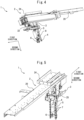
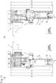
- FIGs. 4 and 5 are a perspective view (part 1) and a perspective view (part 2) of the workpiece transfer device 1, respectively.
- the workpiece transfer device 1 includes a base unit 2, a housing unit 3, a slide unit 4, a grasp base unit 5, a workpiece grasp unit 6, a linear guide unit 7, and a slide unit-moving mechanism 8, and carries out a workpiece W held by the rear spindle 103.
- the workpiece transfer device 1 carries out a workpiece W held by the rear spindle 103; but in the machine tool of the embodiment, the workpiece transfer device 1 may carry a workpiece W into the machine tool or transfer a workpiece W inside the machine tool.
- FIG. 6 is a partial perspective view of a principal part of the workpiece transfer device 1;
- FIGs. 7(a) and 7(b) are a front view and a rear view of the principal part of the workpiece transfer device 1, respectively.
- the base unit 2 includes a base plate 20, a rail 21, a horizontal drive 22, a power feed mechanism 23, and a base connector 24, and is disposed near the ceiling of the casing 105 and inside the machine tool 100.
- the base unit 2 is disposed to extend in the longitudinal direction of the machine tool 100, also referred to as a first direction.
- the base plate 20 is a flat component with the base connector 24 on the upper surface and the rail 21 and the horizontal drive 22 on the lower surface, and is disposed with the long sides extending in the first direction.
- the rail 21 is a bar-shaped component longer than the long sides of the base plate 20 and is disposed to extend parallel to the long sides of the base plate 20.
- the horizontal drive 22 includes a horizontal stepping motor 25 and a rack and pinion 26, and moves the housing unit 3, the slide unit 4, the grasp base unit 5, the workpiece grasp unit 6, the linear guide unit 7, and the slide unit-moving mechanism 8 along the rail 21 in the first direction.
- the power feed mechanism 23 supplies the horizontal stepping motor 25 and a vertical stepping motor 35 included in the housing unit 3 with current depending on control signals output from the NC device 110.
- the base connector 24 is fixed to the casing 105 near the ceiling of the casing 105.
- the horizontal stepping motor 25 supplies power to the horizontal drive 22 in response to current being supplied via the power feed mechanism 23.
- the rack and pinion 26 moves the slide unit 4, the grasp base unit 5, the workpiece grasp unit 6, the linear guide unit 7, and the slide unit-moving mechanism 8 in the first direction in response to the shaft of the horizontal stepping motor 25 being rotated.
- FIGs. 8(a) and 8(b) are a perspective view (part 1) and a perspective view (part 2) of the housing unit 3, respectively.
- the housing unit 3 includes a first base 31, a second base 32, a front board 33, and a rear board 34 in addition to the vertical stepping motor 35, is disposed upright from the base unit 2 in a second direction orthogonal to the first direction in which the base unit 2 extends, and houses the slide unit 4 in a housed position.
- the first base 31 is a U-shaped component including a base 36, a first arm 37, and a second arm 38, and forms a housed position where the slide unit 4 is housed.
- the base 36 is shaped like a flat plate and connected to the horizontal drive 22.
- the first arm 37 is a flat plate extending perpendicularly from an end of one of a pair of long sides of the base 36 in a direction orthogonal to the lengthwise direction of the base 36.
- the second arm 38 is a flat plate extending perpendicularly from an end of the other of the pair of long sides of the base 36 so as to face the first arm 37.
- the second base 32 is connected to the ends of the first arm 37 and the second arm 38 via the front board 33.
- the front board 33 is connected to the first arm 37 and the second arm 38.
- the rear board 34 is a flat component connected to the ends of the first arm 37 and the second arm 38 so as to face the front board 33.
- the rear board 34 has a first cut 39 formed on the edge remote from the base unit 2.
- the vertical stepping motor 35 supplies power to the slide unit-moving mechanism 8 in response to current being supplied via the power feed mechanism 23.
- FIG. 9(a) is a perspective view (part 1) of the housing unit 3, the slide unit 4, the grasp base unit 5, the workpiece grasp unit 6, the linear guide unit 7, and the slide unit-moving mechanism 8.
- FIG. 9(b) is a perspective view (part 2) of the housing unit 3, the slide unit 4, the grasp base unit 5, the workpiece grasp unit 6, the linear guide unit 7, and the slide unit-moving mechanism 8.
- the slide unit 4 is a flat component having a second cut 40 formed at the end remote from the base unit 2, and is held by the housing unit 3 via the linear guide unit 7 so as to be capable of moving in the second direction between the housed position where the slide unit is housed in the housing unit 3 and a grasp position where a workpiece is grasped.
- the grasp base unit 5, the workpiece grasp unit 6, and the slide unit-moving mechanism 8 are disposed on a first surface 41 of the slide unit 4 whereas the linear guide unit 7 is disposed on a second surface 42 of the slide unit 4 opposite the first surface 41.
- FIG. 10 is a perspective view of the grasp base unit 5.
- the grasp base unit 5 includes a grasp driver 50, first and second grasp unit-supporting plates 51 and 52, first and second cutting oil nozzles 53 and 54, and a cover 55, and supports the workpiece grasp unit 6 movably in the width direction of the slide unit 4.
- the grasp driver 50 moves the workpiece grasp unit 6 supported by the first and second grasp unit-supporting plates 51 and 52 in the width direction of the slide unit 4 in response to compressed air being supplied.
- the grasp driver 50 moves the first and second grasp unit-supporting plates 51 and 52 outward.
- the grasp driver 50 moves the first and second grasp unit-supporting plates 51 and 52 inward.
- the first and second grasp unit-supporting plates 51 and 52 are flat components, are movably held by the grasp driver 50, and support the workpiece grasp unit 6.
- the first and second cutting oil nozzles 53 and 54 discharge cutting oil onto a workpiece W grasped by the workpiece grasp unit 6 when the workpiece W is machined.
- the cover 55 is disposed to cover the grasp driver 50, the first and second grasp unit-supporting plates 51 and 52, and the first and second cutting oil nozzles 53 and 54.
- the workpiece grasp unit 6 is supported by the first and second grasp unit-supporting plates 51 and 52 of the grasp driver 50, and moves in response to the grasp driver 50 moving the first and second grasp unit-supporting plates 51 and 52.
- the workpiece grasp unit 6 releases a workpiece W at the open position and grasps a workpiece W at the closed position.
- the grasp base unit 5 and the workpiece grasp unit 6 are also referred to as an air chuck.
- FIGs. 11(a) and 11(b) are a front view and a rear view of the workpiece transfer device 1, respectively.
- a first separation distance L1 which is the distance between the base unit 2 and an end of the workpiece grasp unit 6 adjacent to the base unit 2, is less than a second separation distance L2, which is the distance between the base unit 2 and an end of the slide unit 4 remote from the base unit 2.
- Each of the first, second, and second separation distances L1, L2, and L3 is the distance in the second direction between a desired reference position on the base unit 2 and the slide unit 4 or the workpiece grasp unit 6.
- the reference position on the base unit 2 for defining the first, second, and second separation distances L1, L2, and L3 may be, for example, on the lower or upper surface of the base plate 20.
- the linear guide unit 7 includes a first linear guide 71 and a second linear guide 72, and guides the slide unit 4 in the second direction.
- the first linear guide 71 includes a first rail 73 and a first holder 74, and is disposed on the second surface 42 along one of a pair of long sides extending in the second direction of the slide unit 4.
- the second linear guide 72 includes a second rail 75 and a second holder 76, and is disposed on the second surface 42 along the other of the pair of long sides extending in the second direction of the slide unit 4.
- the first rail 73 and the second rail 75 are disposed along the long sides of the slide unit 4.
- the first holder 74 and the second holder 76 are recirculating ball linear bearings, also referred to as roller guides, and are disposed on the rear board 34.
- FIG. 12 is a partial perspective view of the workpiece transfer device 1 from which the vertical stepping motor 35 is removed.
- the slide unit-moving mechanism 8 includes a rack gear 81 and a pinion 82.
- the rack gear 81 is disposed on the first surface 41 along one of the pair of long sides extending in the second direction of the slide unit 4.
- the pinion 82 is screwed to the rack gear 81 and also fitted to the shaft of the vertical stepping motor 35.
- the pinion 82 rotates in response to the shaft of the vertical stepping motor 35 being rotated, and moves the screwed rack gear 81 to move the slide unit 4 along the first direction.
- FIGs. 13(a) and 13(b) are a front view and a rear view of the workpiece transfer device 1 grasping a workpiece W at the housed position, respectively.
- FIGs. 14(a) and 14(b) are a front view and a rear view of the workpiece transfer device 1 grasping a workpiece W at the grasp position, respectively.
- a workpiece W grasped by the workpiece transfer device 1 is disposed inside the second cut 40 formed in the slide unit 4, and is seen over the second cut 40 when viewed from the front.
- a workpiece W grasped by the workpiece transfer device 1 is disposed inside the first cut 39 formed in the rear board 34 as well as inside the second cut 40, and is seen over the first cut 39 and the second cut 40 when viewed from the front.
- the workpiece grasp unit 6 is disposed over the second cut 40 of the slide unit 4 when the workpiece transfer device 1 is viewed from the front, and is thus disposed without projecting from the end of the slide unit 4 remote from the base unit 2.
- the workpiece grasp unit 6, which is disposed without projecting from the end of the slide unit 4 remote from the base unit 2 is shorter in the second direction than when the workpiece grasp unit projects from the slide unit 4, and can be downsized.
- the workpiece transfer device 1 is short in the second direction, and thus can be disposed near the ceiling inside the machine tool 100.
- the workpiece transfer device 1 since a workpiece W is disposed inside the first cut 39 and the second cut 40 at the housed position, the bottom of the workpiece W is above that of the slide unit 4. Since the bottom of a workpiece W is above that of the slide unit 4, the workpiece W can be moved in the first direction without projecting from the bottom of the slide unit 4.
- the length of the housing unit 3 in the second direction can be minimized with a workpiece W disposed inside the second cut 40 at the housed position.
- the lengths of the first rail 73 and the second rail 75 can be maximized with a workpiece W disposed inside the first cut 39 at the housed position.
- the workpiece transfer device 1 can be more rigid than a workpiece transfer device without a slide unit.
- the rigidity of the workpiece transfer device 1 can be further increased.
- the slide unit 4 can be guided in the second direction with high accuracy by the first rail 73 and the second rail 75 being disposed along the long sides of the slide unit 4.
- the workpiece grasp unit 6 is disposed so as to be seen near the first rail 73 and the second rail 75 when viewed from the front in the first direction, the width of the workpiece transfer device 1 can be minimized.
- the linear guide unit 7 is disposed on the second surface 42 of the slide unit 4 opposite the first surface 41 where the grasp base unit 5 and the workpiece grasp unit 6 are disposed; the slide unit-moving mechanism 8 is disposed on the first surface 41 of the slide unit 4 where the grasp base unit 5 and the workpiece grasp unit 6 are disposed.
- the workpiece transfer device 1 can be downsized by optimizing the arrangement of the linear guide unit 7 and the slide unit-moving mechanism 8.
- the third separation distance L3 may be equal to or greater than the second separation distance L2.
- the linear guide unit 7 includes the first linear guide 71 and the second linear guide 72; however, in the workpiece transfer device of the embodiment, the linear guide unit may include a single rail and holder.
- the first cut 39 is formed in the rear board 34; however, in the workpiece transfer device of the embodiment, no cut may be formed in the rear board.
- the first holder 74 and the second holder 76 are disposed between the workpiece grasp unit 6 and the base unit 2.
- the machine tool 100 includes two spindles, the front spindle 102 and the rear spindle 103; however, the machine tool of the embodiment may include a single spindle.
Landscapes
- Engineering & Computer Science (AREA)
- Mechanical Engineering (AREA)
- General Engineering & Computer Science (AREA)
- Feeding Of Workpieces (AREA)
- Turning (AREA)
- Specific Conveyance Elements (AREA)
Abstract
Description
- The present disclosure relates to a workpiece transfer device and a machine tool.
- A known mechanism rotates a pinion screwed to a rack disposed on a support frame to move chuck hands, which are connected to a lower surface of a board connected to an end of a pair of guide arms and which grasps a workpiece, in the lengthwise direction of the rack (see, e.g., Japanese Unexamined Patent Publication
JP57-163762A JP57-163762A - Further, the use of the mechanism described in the
JP57-163762A - An object of the present disclosure is to provide a workpiece transfer device that can be downsized.
- A workpiece transfer device of the present disclosure includes a base unit extending in a first direction, a housing unit disposed upright from the base unit in a second direction orthogonal to the first direction, a slide unit disposed at a housed position to be housed in the housing unit, a slide unit-moving mechanism configured to move the slide unit from the housed position, a linear guide unit configured to guide the slide unit in the second direction, and a workpiece grasp unit disposed on a first surface of the slide unit near an end of the slide unit remote from the base unit and configured to grasp a workpiece. A separation distance between the base unit and an end of the workpiece grasp unit adjacent to the base unit is less than a separation distance between the base unit and the end of the slide unit remote from the base unit.
- In the workpiece transfer device of the present disclosure, the slide unit preferably has a cut formed at the end remote from the base unit, and at least part of a workpiece grasped by the workpiece grasp unit is preferably disposed inside the cut formed in the slide unit.
- In the workpiece transfer device of the present disclosure, the linear guide unit preferably includes a first linear guide disposed along one of a pair of sides extending in the second direction of the slide unit, and a second linear guide disposed along the other of the pair of sides extending in the second direction of the slide unit.
- In the workpiece transfer device of the present disclosure, the first linear guide preferably includes a first rail disposed on a second surface of the slide unit opposite the first surface and extending in the second direction as well as a first holder disposed on the housing unit and holding the first rail, and the second linear guide preferably includes a second rail disposed on the second surface of the slide unit and extending in the second direction as well as a second holder disposed on the housing unit and holding the second rail.
- In the workpiece transfer device of the present disclosure, the first rail and the second rail are preferably disposed on either side of the cut formed in the slide unit.
- In the workpiece transfer device of the present disclosure, the housing unit preferably has a cut formed at an end remote from the base unit, and the first holder and the second holder are preferably disposed on either side of the cut formed in the housing unit.
- In the workpiece transfer device of the present disclosure, an outer end of the workpiece grasp unit is preferably seen so as to be disposed near the first rail and the second rail when viewed from a front side in the first direction.
- In the workpiece transfer device of the present disclosure, the slide unit-moving mechanism preferably includes a rack gear disposed on the first surface along one of the pair of sides extending in the second direction of the slide unit as well as a pinion screwed to the rack gear.
- In the workpiece transfer device of the present disclosure, a separation distance between the base unit and an end of the workpiece grasp unit remote from the base unit is preferably equal to or less than the separation distance between the base unit and the end of the slide unit remote from the base unit.
- A machine tool according to an aspect of the present disclosure includes a spindle that holds a workpiece rotatably, a tool post that holds a tool for machining a workpiece held by the spindle, and a workpiece transfer device that transfers a workpiece held by the spindle. The workpiece transfer device includes a base unit extending in a first direction, a housing unit disposed upright from the base unit in a second direction orthogonal to the first direction, a slide unit disposed at a housed position to be housed in the housing unit, a slide unit-moving mechanism configured to move the slide unit from the housed position, a linear guide unit configured to guide the slide unit in the second direction, and a workpiece grasp unit disposed on a first surface of the slide unit near an end of the slide unit remote from the base unit and configured to grasp a workpiece. A separation distance between the base unit and an end of the workpiece grasp unit adjacent to the base unit is less than a separation distance between the base unit and the end of the slide unit remote from the base unit.
- The present disclosure enables a workpiece transfer device to be downsized.
-
-
FIG. 1 is a perspective view of a machine tool of an embodiment; -
FIG. 2 is a perspective view of the machine tool shown inFIG. 1 from which a casing is removed; -
FIGs. 3(a) to 3(f) show a workpiece machining process performed by the machine tool shown inFIG. 1 ; FIGs. (a), (b), (c), (d), (e), and (f) show first, second, third, fourth, fifth, and sixth states, respectively; -
FIG. 4 is a perspective view (part 1) of a workpiece transfer device shown inFIG. 2 ; -
FIG. 5 is a perspective view (part 2) of theworkpiece transfer device 1 shown inFIG. 2 ; -
FIG. 6 is a partial perspective view of a principal part of the workpiece transfer device shown inFIG. 2 ; -
FIGs. 7(a) and (b) are a front view and a rear view of the principal part of theworkpiece transfer device 1 shown inFIG. 2 , respectively; -
FIGs. 8(a) and (b) are a perspective view (part 1) and a perspective view (part 2) of a housing unit shown inFIG. 4 , respectively; -
FIG. 9(a) is a perspective view (part 1) of the housing unit, a slide unit, a grasp base unit, a workpiece grasp unit, a linear guide unit, and a slide unit-moving mechanism shown inFIG. 4 ; (b) is a perspective view (part 2) of the housing unit, a slide unit, a grasp base unit, a workpiece grasp unit, a linear guide unit, and a slide unit-moving mechanism shown inFIG. 4 ; -
FIG. 10 is a perspective view of the grasp base unit shown inFIG. 4 ; -
FIGs. 11(a) and (b) are a front view and a rear view of the workpiece transfer device shown inFIG. 2 , respectively; -
FIG. 12 is a partial perspective view of the workpiece transfer device shown inFIG. 2 from which a vertical stepping motor is removed; -
FIGs. 13(a) and (b) are a front view and a rear view of the workpiece transfer device shown inFIG. 2 grasping a workpiece W at a housed position, respectively; and -
FIGs. 14(a) and (b) are a front view and a rear view of the workpiece transfer device shown inFIG. 2 grasping a workpiece W at a grasp position, respectively. - A workpiece transfer device and a machine tool of an embodiment will now be described with reference to the attached drawings. However, note that the technical scope of the present invention is not limited to embodiments thereof and covers the invention described in the claims and equivalents thereof.
-
FIG. 1 is a perspective view of a machine tool of an embodiment;FIG. 2 is a perspective view of the machine tool shown inFIG. 1 from which a casing is removed. - The
machine tool 100 is a slant-type machine tool including abed 101 disposed in an inclined manner, afront spindle 102, arear spindle 103, aturret tool post 104, acasing 105, anNC device 110, and aworkpiece transfer device 1. Thebed 101 is equipped with thefront spindle 102, therear spindle 103, and theturret tool post 104, which are housed in thecasing 105. Thefront spindle 102 is a component that can grasp a workpiece, and is fixed to thebed 101. Therear spindle 103 is a component that can grasp a workpiece grasped by thefront spindle 102, and can move in two directions, X- and Y-axis directions, by being installed on a movingmechanism 106 that moves along the X- and Y-axis directions. Theturret tool post 104 holds various tools and can move in three directions, X-, Y-, and Z-axis directions, by being installed on amoving mechanism 107 that moves along the X-, Y-, and Z-axis directions. The rotation of thefront spindle 102 and therear spindle 103 and the movement of therear spindle 103 and theturret tool post 104 are controlled by theNC device 110. -
FIGs. 3(a) to 3(f) show a workpiece machining process performed by themachine tool 100;FIGs. 3(a), 3(b), 3(c), 3(d), 3(e), and 3(f) show first, second, third, fourth, fifth, and sixth states, respectively. - First, in the first state, the
front spindle 102 holds a workpiece W. Then, in the second state, thefront spindle 102 rotates the workpiece W and theturret tool post 104 moves atool 108, so that the workpiece W is machined by thetool 108 held by theturret tool post 104. When thetool 108 finishes machining the workpiece W, therear spindle 103 moves to a position near thefront spindle 102 and grasps the workpiece W machined by thetool 108. Then, in the third state, therear spindle 103 rotates the workpiece W and theturret tool post 104 moves atool 109, so that the workpiece W is machined by thetool 109 held by theturret tool post 104. After the completion of machining of the workpiece held by therear spindle 103, in the fourth state theworkpiece transfer device 1 grasps the workpiece W held by therear spindle 103. Then, in the fifth state, theworkpiece transfer device 1 lifts the grasped workpiece W and moves it horizontally as indicated by an arrow. In the sixth state, theworkpiece transfer device 1 carries the grasped workpiece W out of themachine tool 100, and the machining of the next workpiece W is started. -
FIGs. 4 and 5 are a perspective view (part 1) and a perspective view (part 2) of theworkpiece transfer device 1, respectively. - The
workpiece transfer device 1 includes abase unit 2, ahousing unit 3, aslide unit 4, agrasp base unit 5, aworkpiece grasp unit 6, alinear guide unit 7, and a slide unit-moving mechanism 8, and carries out a workpiece W held by therear spindle 103. In themachine tool 100, theworkpiece transfer device 1 carries out a workpiece W held by therear spindle 103; but in the machine tool of the embodiment, theworkpiece transfer device 1 may carry a workpiece W into the machine tool or transfer a workpiece W inside the machine tool. -
FIG. 6 is a partial perspective view of a principal part of theworkpiece transfer device 1;FIGs. 7(a) and 7(b) are a front view and a rear view of the principal part of theworkpiece transfer device 1, respectively. - The
base unit 2 includes abase plate 20, arail 21, ahorizontal drive 22, a power feed mechanism 23, and abase connector 24, and is disposed near the ceiling of thecasing 105 and inside themachine tool 100. Thebase unit 2 is disposed to extend in the longitudinal direction of themachine tool 100, also referred to as a first direction. Thebase plate 20 is a flat component with thebase connector 24 on the upper surface and therail 21 and thehorizontal drive 22 on the lower surface, and is disposed with the long sides extending in the first direction. Therail 21 is a bar-shaped component longer than the long sides of thebase plate 20 and is disposed to extend parallel to the long sides of thebase plate 20. Thehorizontal drive 22 includes ahorizontal stepping motor 25 and a rack andpinion 26, and moves thehousing unit 3, theslide unit 4, thegrasp base unit 5, theworkpiece grasp unit 6, thelinear guide unit 7, and the slide unit-moving mechanism 8 along therail 21 in the first direction. The power feed mechanism 23 supplies thehorizontal stepping motor 25 and avertical stepping motor 35 included in thehousing unit 3 with current depending on control signals output from theNC device 110. Thebase connector 24 is fixed to thecasing 105 near the ceiling of thecasing 105. Thehorizontal stepping motor 25 supplies power to thehorizontal drive 22 in response to current being supplied via the power feed mechanism 23. The rack andpinion 26 moves theslide unit 4, thegrasp base unit 5, theworkpiece grasp unit 6, thelinear guide unit 7, and the slide unit-movingmechanism 8 in the first direction in response to the shaft of thehorizontal stepping motor 25 being rotated. -
FIGs. 8(a) and 8(b) are a perspective view (part 1) and a perspective view (part 2) of thehousing unit 3, respectively. - The
housing unit 3 includes afirst base 31, asecond base 32, afront board 33, and arear board 34 in addition to thevertical stepping motor 35, is disposed upright from thebase unit 2 in a second direction orthogonal to the first direction in which thebase unit 2 extends, and houses theslide unit 4 in a housed position. Thefirst base 31 is a U-shaped component including abase 36, afirst arm 37, and asecond arm 38, and forms a housed position where theslide unit 4 is housed. Thebase 36 is shaped like a flat plate and connected to thehorizontal drive 22. Thefirst arm 37 is a flat plate extending perpendicularly from an end of one of a pair of long sides of the base 36 in a direction orthogonal to the lengthwise direction of thebase 36. Thesecond arm 38 is a flat plate extending perpendicularly from an end of the other of the pair of long sides of the base 36 so as to face thefirst arm 37. Thesecond base 32 is connected to the ends of thefirst arm 37 and thesecond arm 38 via thefront board 33. Thefront board 33 is connected to thefirst arm 37 and thesecond arm 38. - The
rear board 34 is a flat component connected to the ends of thefirst arm 37 and thesecond arm 38 so as to face thefront board 33. Therear board 34 has afirst cut 39 formed on the edge remote from thebase unit 2. Thevertical stepping motor 35 supplies power to the slide unit-movingmechanism 8 in response to current being supplied via the power feed mechanism 23. -
FIG. 9(a) is a perspective view (part 1) of thehousing unit 3, theslide unit 4, thegrasp base unit 5, theworkpiece grasp unit 6, thelinear guide unit 7, and the slide unit-movingmechanism 8.FIG. 9(b) is a perspective view (part 2) of thehousing unit 3, theslide unit 4, thegrasp base unit 5, theworkpiece grasp unit 6, thelinear guide unit 7, and the slide unit-movingmechanism 8. - The
slide unit 4 is a flat component having asecond cut 40 formed at the end remote from thebase unit 2, and is held by thehousing unit 3 via thelinear guide unit 7 so as to be capable of moving in the second direction between the housed position where the slide unit is housed in thehousing unit 3 and a grasp position where a workpiece is grasped. Thegrasp base unit 5, theworkpiece grasp unit 6, and the slide unit-movingmechanism 8 are disposed on afirst surface 41 of theslide unit 4 whereas thelinear guide unit 7 is disposed on asecond surface 42 of theslide unit 4 opposite thefirst surface 41. -
FIG. 10 is a perspective view of thegrasp base unit 5. - The
grasp base unit 5 includes agrasp driver 50, first and second grasp unit-supportingplates oil nozzles cover 55, and supports theworkpiece grasp unit 6 movably in the width direction of theslide unit 4. Thegrasp driver 50 moves theworkpiece grasp unit 6 supported by the first and second grasp unit-supportingplates slide unit 4 in response to compressed air being supplied. When compressed air is supplied so that theworkpiece grasp unit 6 is in an open position to release a workpiece W, thegrasp driver 50 moves the first and second grasp unit-supportingplates workpiece grasp unit 6 is in a closed position to grasp a workpiece W, thegrasp driver 50 moves the first and second grasp unit-supportingplates - The first and second grasp unit-supporting
plates grasp driver 50, and support theworkpiece grasp unit 6. The first and second cuttingoil nozzles workpiece grasp unit 6 when the workpiece W is machined. Thecover 55 is disposed to cover thegrasp driver 50, the first and second grasp unit-supportingplates oil nozzles - The
workpiece grasp unit 6 is supported by the first and second grasp unit-supportingplates grasp driver 50, and moves in response to thegrasp driver 50 moving the first and second grasp unit-supportingplates workpiece grasp unit 6 releases a workpiece W at the open position and grasps a workpiece W at the closed position. Thegrasp base unit 5 and theworkpiece grasp unit 6 are also referred to as an air chuck. -
FIGs. 11(a) and 11(b) are a front view and a rear view of theworkpiece transfer device 1, respectively. - A first separation distance L1, which is the distance between the
base unit 2 and an end of theworkpiece grasp unit 6 adjacent to thebase unit 2, is less than a second separation distance L2, which is the distance between thebase unit 2 and an end of theslide unit 4 remote from thebase unit 2. A third separation distance L3, which is the distance between thebase unit 2 and an end of theworkpiece grasp unit 6 remote from thebase unit 2, is less than the second separation distance L2, which is the distance between thebase unit 2 and the end of theslide unit 4 remote from thebase unit 2. Since the third separation distance L3 is less than the second separation distance L2, theworkpiece grasp unit 6 is disposed over thesecond cut 40 of theslide unit 4 when the workpiece transfer device is viewed from the front. - Each of the first, second, and second separation distances L1, L2, and L3 is the distance in the second direction between a desired reference position on the
base unit 2 and theslide unit 4 or theworkpiece grasp unit 6. The reference position on thebase unit 2 for defining the first, second, and second separation distances L1, L2, and L3 may be, for example, on the lower or upper surface of thebase plate 20. - As shown in
FIG. 9 , thelinear guide unit 7 includes a firstlinear guide 71 and a secondlinear guide 72, and guides theslide unit 4 in the second direction. The firstlinear guide 71 includes a first rail 73 and afirst holder 74, and is disposed on thesecond surface 42 along one of a pair of long sides extending in the second direction of theslide unit 4. The secondlinear guide 72 includes a second rail 75 and asecond holder 76, and is disposed on thesecond surface 42 along the other of the pair of long sides extending in the second direction of theslide unit 4. The first rail 73 and the second rail 75 are disposed along the long sides of theslide unit 4. Thefirst holder 74 and thesecond holder 76 are recirculating ball linear bearings, also referred to as roller guides, and are disposed on therear board 34. -
FIG. 12 is a partial perspective view of theworkpiece transfer device 1 from which thevertical stepping motor 35 is removed. - The slide unit-moving
mechanism 8 includes a rack gear 81 and apinion 82. The rack gear 81 is disposed on thefirst surface 41 along one of the pair of long sides extending in the second direction of theslide unit 4. Thepinion 82 is screwed to the rack gear 81 and also fitted to the shaft of thevertical stepping motor 35. Thepinion 82 rotates in response to the shaft of thevertical stepping motor 35 being rotated, and moves the screwed rack gear 81 to move theslide unit 4 along the first direction. -
FIGs. 13(a) and 13(b) are a front view and a rear view of theworkpiece transfer device 1 grasping a workpiece W at the housed position, respectively.FIGs. 14(a) and 14(b) are a front view and a rear view of theworkpiece transfer device 1 grasping a workpiece W at the grasp position, respectively. - At both the housed position and the grasp position, a workpiece W grasped by the
workpiece transfer device 1 is disposed inside thesecond cut 40 formed in theslide unit 4, and is seen over thesecond cut 40 when viewed from the front. At the housed position, a workpiece W grasped by theworkpiece transfer device 1 is disposed inside thefirst cut 39 formed in therear board 34 as well as inside thesecond cut 40, and is seen over thefirst cut 39 and thesecond cut 40 when viewed from the front. - In the
workpiece transfer device 1, theworkpiece grasp unit 6 is disposed over thesecond cut 40 of theslide unit 4 when theworkpiece transfer device 1 is viewed from the front, and is thus disposed without projecting from the end of theslide unit 4 remote from thebase unit 2. In theworkpiece transfer device 1, theworkpiece grasp unit 6, which is disposed without projecting from the end of theslide unit 4 remote from thebase unit 2, is shorter in the second direction than when the workpiece grasp unit projects from theslide unit 4, and can be downsized. Theworkpiece transfer device 1 is short in the second direction, and thus can be disposed near the ceiling inside themachine tool 100. - In the
workpiece transfer device 1, since a workpiece W is disposed inside thefirst cut 39 and thesecond cut 40 at the housed position, the bottom of the workpiece W is above that of theslide unit 4. Since the bottom of a workpiece W is above that of theslide unit 4, the workpiece W can be moved in the first direction without projecting from the bottom of theslide unit 4. - In the
workpiece transfer device 1, since the first rail 73 and the second rail 75 are disposed on either side of thesecond cut 40, the length of thehousing unit 3 in the second direction can be minimized with a workpiece W disposed inside thesecond cut 40 at the housed position. - In the
workpiece transfer device 1, since thefirst holder 74 and thesecond holder 76 are disposed on either side of thefirst cut 39, the lengths of the first rail 73 and the second rail 75 can be maximized with a workpiece W disposed inside thefirst cut 39 at the housed position. - Since the
slide unit 4, which is a flat component, is included, theworkpiece transfer device 1 can be more rigid than a workpiece transfer device without a slide unit. - In the
workpiece transfer device 1, since the first rail 73 of the firstlinear guide 71 and the second rail 75 of the secondlinear guide 72 are disposed to extend in the second direction along the long sides of theslide unit 4, the rigidity of theworkpiece transfer device 1 can be further increased. Theslide unit 4 can be guided in the second direction with high accuracy by the first rail 73 and the second rail 75 being disposed along the long sides of theslide unit 4. - In the
workpiece transfer device 1, since theworkpiece grasp unit 6 is disposed so as to be seen near the first rail 73 and the second rail 75 when viewed from the front in the first direction, the width of theworkpiece transfer device 1 can be minimized. - In the
workpiece transfer device 1, thelinear guide unit 7 is disposed on thesecond surface 42 of theslide unit 4 opposite thefirst surface 41 where thegrasp base unit 5 and theworkpiece grasp unit 6 are disposed; the slide unit-movingmechanism 8 is disposed on thefirst surface 41 of theslide unit 4 where thegrasp base unit 5 and theworkpiece grasp unit 6 are disposed. Theworkpiece transfer device 1 can be downsized by optimizing the arrangement of thelinear guide unit 7 and the slide unit-movingmechanism 8. - In the
workpiece transfer device 1, the third separation distance L3, which is the distance between thebase unit 2 and the end of theworkpiece grasp unit 6 remote from thebase unit 2, is less than the second separation distance L2, which is the distance between thebase unit 2 and the end of theslide unit 4 remote from thebase unit 2. However, in the workpiece transfer device of the embodiment, the third separation distance L3 may be equal to or greater than the second separation distance L2. - In the
workpiece transfer device 1, thelinear guide unit 7 includes the firstlinear guide 71 and the secondlinear guide 72; however, in the workpiece transfer device of the embodiment, the linear guide unit may include a single rail and holder. - In the
workpiece transfer device 1, thefirst cut 39 is formed in therear board 34; however, in the workpiece transfer device of the embodiment, no cut may be formed in the rear board. When no cut is formed in the rear board, thefirst holder 74 and thesecond holder 76 are disposed between theworkpiece grasp unit 6 and thebase unit 2. - The
machine tool 100 includes two spindles, thefront spindle 102 and therear spindle 103; however, the machine tool of the embodiment may include a single spindle.
Claims (10)
- A workpiece transfer device comprising:a base unit extending in a first direction;a housing unit disposed upright from the base unit in a second direction orthogonal to the first direction;a slide unit disposed at a housed position to be housed in the housing unit;a slide unit-moving mechanism configured to move the slide unit from the housed position;a linear guide unit configured to guide the slide unit in the second direction; anda workpiece grasp unit disposed on a first surface of the slide unit near an end of the slide unit remote from the base unit and configured to grasp a workpiece, whereina separation distance between the base unit and an end of the workpiece grasp unit adjacent to the base unit is less than a separation distance between the base unit and the end of the slide unit remote from the base unit.
- The workpiece transfer device according to claim 1, wherein the slide unit has a cut formed at the end remote from the base unit, and
at least part of a workpiece grasped by the workpiece grasp unit is disposed inside the cut formed in the slide unit. - The workpiece transfer device according to claim 2, wherein the linear guide unit includesa first linear guide disposed along one of a pair of sides extending in the second direction of the slide unit; anda second linear guide disposed along the other of the pair of sides extending in the second direction of the slide unit.
- The workpiece transfer device according to claim 3, wherein the first linear guide includes a first rail disposed on a second surface of the slide unit opposite the first surface and extending in the second direction as well as a first holder disposed on the housing unit and holding the first rail, and
the second linear guide includes a second rail disposed on the second surface of the slide unit and extending in the second direction as well as a second holder disposed on the housing unit and holding the second rail. - The workpiece transfer device according to claim 4, wherein the first rail and the second rail are disposed on either side of the cut formed in the slide unit.
- The workpiece transfer device according to claim 4, wherein the housing unit has a cut formed at an end remote from the base unit, and
the first holder and the second holder are disposed on either side of the cut formed in the housing unit. - The workpiece transfer device according to claim 5, wherein an outer end of the workpiece grasp unit is disposed so as to be seen near the first rail and the second rail when viewed from a front side in the first direction.
- The workpiece transfer device according to claim 4, wherein the slide unit-moving mechanism includes a rack gear disposed on the first surface along one of the pair of sides extending in the second direction of the slide unit as well as a pinion screwed to the rack gear.
- The workpiece transfer device according to any one of claims 1 to 8, wherein a separation distance between the base unit and an end of the workpiece grasp unit remote from the base unit is equal to or less than the separation distance between the base unit and the end of the slide unit remote from the base unit.
- A machine tool comprising:a spindle that holds a workpiece rotatably;a tool post that holds a tool for machining a workpiece held by the spindle; anda workpiece transfer device that transfers a workpiece held by the spindle,the workpiece transfer device comprising:a base unit extending in a first direction;a housing unit disposed upright from the base unit in a second direction orthogonal to the first direction;a slide unit disposed at a housed position to be housed in the housing unit;a slide unit-moving mechanism configured to move the slide unit from the housed position;a linear guide unit configured to guide the slide unit in the second direction; anda workpiece grasp unit disposed on a first surface of the slide unit near an end of the slide unit remote from the base unit and configured to grasp a workpiece, whereina separation distance between the base unit and an end of the workpiece grasp unit adjacent to the base unit is less than a separation distance between the base unit and the end of the slide unit remote from the base unit.
Applications Claiming Priority (2)
| Application Number | Priority Date | Filing Date | Title |
|---|---|---|---|
| JP2022120778A JP2024017858A (en) | 2022-07-28 | 2022-07-28 | Workpiece conveyance equipment and machine tools |
| PCT/JP2023/027634 WO2024024904A1 (en) | 2022-07-28 | 2023-07-27 | Workpiece transfer device and machine tool |
Publications (2)
| Publication Number | Publication Date |
|---|---|
| EP4563281A1 true EP4563281A1 (en) | 2025-06-04 |
| EP4563281A4 EP4563281A4 (en) | 2026-07-01 |
Family
ID=89706534
Family Applications (1)
| Application Number | Title | Priority Date | Filing Date |
|---|---|---|---|
| EP23846634.6A Pending EP4563281A4 (en) | 2022-07-28 | 2023-07-27 | WORKPIECE TRANSFER DEVICE AND MACHINE TOOL |
Country Status (7)
| Country | Link |
|---|---|
| US (1) | US20260014629A1 (en) |
| EP (1) | EP4563281A4 (en) |
| JP (1) | JP2024017858A (en) |
| KR (1) | KR20250034310A (en) |
| CN (1) | CN119585076A (en) |
| TW (1) | TW202412968A (en) |
| WO (1) | WO2024024904A1 (en) |
Family Cites Families (7)
| Publication number | Priority date | Publication date | Assignee | Title |
|---|---|---|---|---|
| JPS57163762A (en) * | 1981-03-31 | 1982-10-08 | Toshiba Mach Co Ltd | Stroke magnifying mechanism for arms |
| JPH0266932U (en) * | 1988-11-07 | 1990-05-21 | ||
| JPH0633690U (en) * | 1992-10-06 | 1994-05-06 | 日立精機株式会社 | Traverse robot |
| JPH0740266A (en) * | 1993-07-29 | 1995-02-10 | Yaskawa Electric Corp | Direct acting loader |
| JP6619947B2 (en) * | 2015-03-31 | 2019-12-11 | Dmg森精機株式会社 | Work loader device |
| CN105665749B (en) * | 2016-03-11 | 2017-11-21 | 温岭市科宇自动化设备有限公司 | A kind of digital-control two-head lathe |
| CN109249038A (en) * | 2018-10-25 | 2019-01-22 | 辽宁工业大学 | A kind of automatic loading unloading device of digital controlled lathe |
-
2022
- 2022-07-28 JP JP2022120778A patent/JP2024017858A/en active Pending
-
2023
- 2023-07-27 KR KR1020247043251A patent/KR20250034310A/en active Pending
- 2023-07-27 WO PCT/JP2023/027634 patent/WO2024024904A1/en not_active Ceased
- 2023-07-27 EP EP23846634.6A patent/EP4563281A4/en active Pending
- 2023-07-27 US US18/995,238 patent/US20260014629A1/en active Pending
- 2023-07-27 CN CN202380054903.5A patent/CN119585076A/en active Pending
- 2023-07-28 TW TW112128414A patent/TW202412968A/en unknown
Also Published As
| Publication number | Publication date |
|---|---|
| TW202412968A (en) | 2024-04-01 |
| US20260014629A1 (en) | 2026-01-15 |
| JP2024017858A (en) | 2024-02-08 |
| WO2024024904A1 (en) | 2024-02-01 |
| CN119585076A (en) | 2025-03-07 |
| KR20250034310A (en) | 2025-03-11 |
| EP4563281A4 (en) | 2026-07-01 |
Similar Documents
| Publication | Publication Date | Title |
|---|---|---|
| JP4234514B2 (en) | NC lathe | |
| EP1116548A2 (en) | A machine tool having a vertical main spindle and a method of making the same | |
| US4951376A (en) | Machine tool | |
| JP5084605B2 (en) | Machine Tools | |
| US9700975B2 (en) | Five-axis machining apparatus | |
| EP0357775A1 (en) | Pallet replacing apparatus | |
| US4704773A (en) | Machine tool structure | |
| KR20100118079A (en) | Combined lathe and processing method of work | |
| CN100553870C (en) | The horizontal mechanical machining center | |
| JPH06126518A (en) | Milling head | |
| US20160368060A1 (en) | Machine tool | |
| US20260014629A1 (en) | Workpiece transfer device and machine tool | |
| CN120715683A (en) | Tool magazine assembly of machine tool and machine tool | |
| JP4827912B2 (en) | Machine tool system | |
| CN104802013B (en) | A kind of numerical control machining center of multiaspect processing | |
| KR20100118068A (en) | shelf | |
| CN1153641C (en) | lathe | |
| JP4522684B2 (en) | Machine Tools | |
| JPH0620706B2 (en) | Pallet replacement method | |
| JP2005028481A (en) | Machine Tools | |
| CN209240760U (en) | A kind of carving machine of manipulator forward type | |
| CN216829871U (en) | Snatch mechanism and PCB processing equipment | |
| JP7617265B2 (en) | Multi-tasking machine | |
| CN222289510U (en) | A feeding mechanism for workpiece processing | |
| CN114700759B (en) | Special processing equipment for inner cavity of cylindrical part |
Legal Events
| Date | Code | Title | Description |
|---|---|---|---|
| STAA | Information on the status of an ep patent application or granted ep patent |
Free format text: STATUS: THE INTERNATIONAL PUBLICATION HAS BEEN MADE |
|
| PUAI | Public reference made under article 153(3) epc to a published international application that has entered the european phase |
Free format text: ORIGINAL CODE: 0009012 |
|
| STAA | Information on the status of an ep patent application or granted ep patent |
Free format text: STATUS: REQUEST FOR EXAMINATION WAS MADE |
|
| 17P | Request for examination filed |
Effective date: 20250102 |
|
| AK | Designated contracting states |
Kind code of ref document: A1 Designated state(s): AL AT BE BG CH CY CZ DE DK EE ES FI FR GB GR HR HU IE IS IT LI LT LU LV MC ME MK MT NL NO PL PT RO RS SE SI SK SM TR |
|
| DAV | Request for validation of the european patent (deleted) | ||
| DAX | Request for extension of the european patent (deleted) | ||
| A4 | Supplementary search report drawn up and despatched |
Effective date: 20260603 |
|
| RIC1 | Information provided on ipc code assigned before grant |
Ipc: B23Q 7/04 20060101AFI20260528BHEP Ipc: B23B 13/02 20060101ALI20260528BHEP |