EP4563264A1 - Casting mold, control equipment, and continuous casting method for steel - Google Patents
Casting mold, control equipment, and continuous casting method for steel Download PDFInfo
- Publication number
- EP4563264A1 EP4563264A1 EP23871333.3A EP23871333A EP4563264A1 EP 4563264 A1 EP4563264 A1 EP 4563264A1 EP 23871333 A EP23871333 A EP 23871333A EP 4563264 A1 EP4563264 A1 EP 4563264A1
- Authority
- EP
- European Patent Office
- Prior art keywords
- mold
- optical fiber
- temperature sensor
- fiber temperature
- copper plate
- Prior art date
- Legal status (The legal status is an assumption and is not a legal conclusion. Google has not performed a legal analysis and makes no representation as to the accuracy of the status listed.)
- Pending
Links
Images




Classifications
-
- B—PERFORMING OPERATIONS; TRANSPORTING
- B22—CASTING; POWDER METALLURGY
- B22D—CASTING OF METALS; CASTING OF OTHER SUBSTANCES BY THE SAME PROCESSES OR DEVICES
- B22D2/00—Arrangement of indicating or measuring devices, e.g. for temperature or viscosity of the fused mass
- B22D2/006—Arrangement of indicating or measuring devices, e.g. for temperature or viscosity of the fused mass for the temperature of the molten metal
-
- B—PERFORMING OPERATIONS; TRANSPORTING
- B22—CASTING; POWDER METALLURGY
- B22D—CASTING OF METALS; CASTING OF OTHER SUBSTANCES BY THE SAME PROCESSES OR DEVICES
- B22D11/00—Continuous casting of metals, i.e. casting in indefinite lengths
- B22D11/16—Controlling or regulating processes or operations
- B22D11/20—Controlling or regulating processes or operations for removing cast stock
- B22D11/201—Controlling or regulating processes or operations for removing cast stock responsive to molten metal level or slag level
- B22D11/202—Controlling or regulating processes or operations for removing cast stock responsive to molten metal level or slag level by measuring temperature
-
- B—PERFORMING OPERATIONS; TRANSPORTING
- B22—CASTING; POWDER METALLURGY
- B22D—CASTING OF METALS; CASTING OF OTHER SUBSTANCES BY THE SAME PROCESSES OR DEVICES
- B22D11/00—Continuous casting of metals, i.e. casting in indefinite lengths
- B22D11/16—Controlling or regulating processes or operations
-
- B—PERFORMING OPERATIONS; TRANSPORTING
- B22—CASTING; POWDER METALLURGY
- B22D—CASTING OF METALS; CASTING OF OTHER SUBSTANCES BY THE SAME PROCESSES OR DEVICES
- B22D11/00—Continuous casting of metals, i.e. casting in indefinite lengths
- B22D11/16—Controlling or regulating processes or operations
- B22D11/168—Controlling or regulating processes or operations for adjusting the mould size or mould taper
-
- B—PERFORMING OPERATIONS; TRANSPORTING
- B22—CASTING; POWDER METALLURGY
- B22D—CASTING OF METALS; CASTING OF OTHER SUBSTANCES BY THE SAME PROCESSES OR DEVICES
- B22D11/00—Continuous casting of metals, i.e. casting in indefinite lengths
- B22D11/16—Controlling or regulating processes or operations
- B22D11/18—Controlling or regulating processes or operations for pouring
-
- B—PERFORMING OPERATIONS; TRANSPORTING
- B22—CASTING; POWDER METALLURGY
- B22D—CASTING OF METALS; CASTING OF OTHER SUBSTANCES BY THE SAME PROCESSES OR DEVICES
- B22D11/00—Continuous casting of metals, i.e. casting in indefinite lengths
- B22D11/16—Controlling or regulating processes or operations
- B22D11/18—Controlling or regulating processes or operations for pouring
- B22D11/181—Controlling or regulating processes or operations for pouring responsive to molten metal level or slag level
- B22D11/182—Controlling or regulating processes or operations for pouring responsive to molten metal level or slag level by measuring temperature
Definitions
- the present invention relates to a mold for accurately detecting abnormal phenomena that lead to longitudinal crack defects and breakouts (rupture of a solidified shell) occurring in the solidified shell in the mold during continuous steel casting, a control system capable of predicting longitudinal crack defects and breakouts with high accuracy, and a continuous casting method of steel.
- Examples of the proposed methods of detecting breakouts include a method that detects abnormalities from temperature information obtained from a thermocouple embedded in a mold copper plate, and a method that detects abnormalities from changes in drag or frictional force measured by a measuring device for pressure measurement installed in a mold oscillation system or a mold.
- Patent Literature 1 discloses a method that detects breakouts on the basis of the result of temperature measurement made with sheathed thermocouples embedded at two (upper and lower) levels in a mold copper plate.
- the sheathed thermocouples are embedded at intervals of 100 mm to 200 mm in the width direction of the mold copper plate.
- the intervals between the sheathed thermocouples embedded may be too wide to detect small-scale breakouts, such as longitudinal crack defects, bleeds, and melt leakages. Therefore, there is a problem that detection sometimes slips through.
- An effective way to address such a problem will be to embed the sheathed thermocouples at intervals narrower than 100 mm in the width direction.
- FIG. 1 schematically illustrates a conventional mold copper plate 102 with a backup plate secured to a back side thereof.
- Fig. 1(a) is a back view as viewed from a backup plate side
- Fig. 1(b) is a cross-sectional view taken along line A-A in Fig. 1(a) .
- the mold copper plate 102 has, in the back side thereof, a plurality of slit grooves 106 formed along the casting direction.
- a backup plate 104 is secured with stud bolts 108 to the back side of the mold copper plate 102.
- the slit grooves 106 serve as cooling channels that allow passage of a cooling medium for cooling the mold copper plate 102.
- the mold copper plate 102 has a plurality of sheathed thermocouples 110 embedded therein in the width direction at two different levels in the casting direction of the mold copper plate 102.
- the sheathed thermocouples 110 penetrate the backup plate 104 and are inserted in a skewered manner from the back side of the mold copper plate 102.
- the sheathed thermocouples 110 are arranged to avoid the slit grooves 106. Therefore, the sheathed thermocouples 110 are automatically positioned near the stud bolts 108.
- the stud bolts 108 are arranged at intervals of about 200 mm in the width direction of the mold copper plate 102. Accordingly, like the stud bolts 108, the sheathed thermocouples 110 are arranged at intervals of about 200 mm. To arrange the sheathed thermocouples 110 at intervals of less than or equal to 100 mm, many insertion holes are to be provided in the mold copper plate 102 and the backup plate 104. This lowers the strength of the backup plate 104. To prevent the insertion holes for the sheathed thermocouples 110 from communicating with the slit grooves 106, special processing is required which processes the slit grooves 106 into a curved shape. The wiring of the sheathed thermocouples 110 also needs to be specially configured. Because of the problems described above, the system specifications cannot be changed to shorten the intervals of temperature detection in the width direction.
- An object of the present invention is to provide a mold that can shorten the temperature detection intervals without special processing of slit grooves, a control system including the mold, and a continuous casting method of steel.
- Fig. 2 is a cross-sectional schematic view illustrating an example of a continuous casting system 10 including a mold 12 of the present embodiment and capable of carrying out continuous steel casting.
- the continuous casting system 10 includes the mold 12, a tundish 14 installed above the mold 12, a plurality of cast steel support rolls 16 and conveyance rolls 17 arranged below the mold 12, a plurality of secondary cooling zones 26, a cast steel cutter 30, and a control device 60.
- a ladle containing molten steel 18 is installed above the tundish 14.
- the molten steel 18 is poured from the bottom of the ladle into the tundish 14.
- An immersion nozzle 20 is installed at the bottom of the tundish 14, and the molten steel 18 is poured through the immersion nozzle 20 into the mold 12.
- the molten steel 18 is subjected to heat removal through the inner surface of the mold 12 and solidified to form a solidified shell 22.
- Cast steel 28 is thus formed which includes the solidified shell 22 as an outer shell and an unsolidified layer 24 made of the molten steel 18 therein.
- a plurality of secondary cooling zones 26 including spray nozzles are arranged immediately below the mold 12 along the casting direction. While being pulled out, the cast steel 28 is cooled with cooling water ejected from the spray nozzles in the secondary cooling zones 26. While the cast steel 28 passes through the plurality of secondary cooling zones 26 by being conveyed by the cast steel support rolls 16, the solidified shell 22 is appropriately cooled to promote solidification of the unsolidified layer 24 and complete solidification of the cast steel 28.
- the plurality of conveyance rolls 17 for continuously conveying the cast steel 28 are installed on the downstream side in the casting direction.
- the cast steel cutter 30 for cutting the cast steel 28 is disposed above the conveyance rolls 17. After completion of solidification, the cast steel 28 is cut into a predetermined length by the cast steel cutter 30 to produce a slab 29.
- Fig. 3 is a perspective view illustrating the mold 12 according to the present embodiment.
- the mold 12 is composed of a plurality of mold copper plates.
- the plurality of mold copper plates in the present embodiment are, for example, a pair of mold long-side copper plates 40 and a pair of mold short-side copper plates 42.
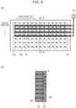
- Fig. 4 schematically illustrates the mold long-side copper plate 40 with a backup plate secured to a back side thereof.
- Fig. 4(a) is a back view as viewed from a backup plate side
- Fig. 4(b) is a cross-sectional view taken along line B-B in Fig. 4(a) .
- the same components as those of the mold copper plate 102 illustrated in Fig. 1 are given the same reference numerals and their description will be omitted.
- the mold long-side copper plate 40 has FBG optical fiber temperature sensors 50 embedded therein.
- the optical fiber temperature sensors 50 are to be normally indicated by a dotted line, as they are embedded in the mold long-side copper plate 40. In Fig. 4(a) , however, the optical fiber temperature sensors 50 are indicated by a solid line to clarify the installation positions of the optical fiber temperature sensors 50.
- the optical fiber temperature sensors in Fig. 7(a) , Fig. 8(a) , and Fig. 9(a) are also illustrated in this manner.
- a fiber Bragg grating (FBG) optical fiber temperature sensor is a temperature sensor including an optical fiber that is provided with a diffraction grating configured to diffract a specific wavelength, so as to detect a temperature using a Bragg diffraction phenomenon in the diffraction grating.
- FBG fiber Bragg grating
- the mold long-side copper plate 40 has, in the back side thereof, a plurality of slit grooves 106 formed along the casting direction.
- a backup plate 44 is secured with stud bolts 108 to the back side of the mold long-side copper plate 40.
- the mold long-side copper plate 40 has the optical fiber temperature sensors 50 embedded therein at four different levels in the casting direction.
- the optical fiber temperature sensors 50 at the four levels are preferably disposed in a range of 50 mm to 600 mm below the meniscus (bath level position) of the mold long-side copper plate 40.
- the first level optical fiber temperature sensor 50 is embedded at a position 50 mm below the meniscus
- the second level optical fiber temperature sensor 50 is embedded at a position 150 mm below the meniscus.
- the third level optical fiber temperature sensor 50 is embedded at a position 250 mm below the meniscus
- the fourth level optical fiber temperature sensor 50 is embedded at a position 350 mm below the meniscus.
- the first to fourth level optical fiber temperature sensors 50 are provided with diffraction gratings 52 at intervals of less than or equal to 50 mm.
- the first to fourth level optical fiber temperature sensors 50 are embedded such that the positions of the diffraction gratings 52 in the width direction are the same at all the levels.
- temperatures are detected at the positions of the respective diffraction gratings 52. Therefore, in the mold long-side copper plate 40 illustrated in Fig. 4 , mold temperatures can be detected which reflect the temperatures of the solidified shell 22 at four different levels in the casting direction, at intervals of less than or equal to 50 mm in the width direction.
- Fig. 5 schematically illustrates how the optical fiber temperature sensors 50 are embedded in the mold long-side copper plate 40.
- Fig. 5(a) is a perspective view illustrating the mold long-side copper plate 40 with holes formed therein.
- Fig. 5(b) is a perspective view illustrating the optical fiber temperature sensor 50.
- Fig. 5(c) is a perspective view illustrating a double pipe 58 composed of the optical fiber temperature sensor 50 and a copper pipe 56.
- the mold long-side copper plate 40 has four holes 48 horizontally formed by electrical discharge machining to extend from one to the other side of the mold long-side copper plate 40.
- the optical fiber temperature sensors 50 are embedded in the mold long-side copper plate 40.
- the optical fiber temperature sensor 50 illustrated in Fig. 5(b) has a diameter of about 1 mm. Therefore, when the optical fiber temperature sensors 50 are inserted and embedded in the mold long-side copper plate 40, the holes 48 with a diameter of about 1 mm corresponding to the diameter of the optical fiber temperature sensors 50 are required over the entire length of the mold long-side copper plate 40 in the width direction.
- the diameter of the holes 48 formed in the mold long-side copper plate 40 by electrical discharge machining is 3 mm to 5 mm. This facilitates electrical discharge machining in the mold long-side copper plate 40.
- the optical fiber temperature sensor 50 can be embedded by inserting the double pipe 58 with rigidity into the mold long-side copper plate 40. This improves workability in embedding the optical fiber temperature sensors 50 into the mold long-side copper plate 40.
- the holes 48 are preferably formed in a region from a position 1 mm from the surface of the mold long-side copper plate 40 adjacent to the molten steel in the thickness direction to a position 1 mm from the groove bottom of the slit grooves 106 in the thickness direction. This can reduce the influence of the surface of the mold long-side copper plate 40 adjacent to the molten steel changed by wear or the like, and the influence of the cooling water temperature and the surface conditions of the slit grooves. It is more preferable that the holes 48 be formed in a region from a position 5 mm from the surface adjacent to the molten steel in the thickness direction to a position 5 mm from the groove bottom of the slit grooves 106 in the thickness direction. This can further reduce the influence of the surface of the mold long-side copper plate 40 adjacent to the molten steel changed by wear or the like, and the influence of the cooling water temperature and the surface conditions of the slit grooves 106.
- the optical fiber temperature sensors 50 can thus be embedded in the mold long-side copper plate 40 without making through holes in the backup plate 44. Additionally, since the holes 48 for embedding the optical fiber temperature sensors 50 are formed not to communicate with the slit grooves 106, there is no need to process the slit grooves 106 into a curved shape. Therefore, the mold 12 of the present embodiment including the mold long-side copper plate 40 is a mold that can shorten the temperature detection intervals in the mold width direction without special processing of the slit grooves 106. Additionally, since the optical fiber temperature sensors 50 can be embedded in the mold long-side copper plate 40 without making through holes in the backup plate 44, a decrease in the strength of the backup plate 44 can be suppressed.
- an interrogator 54 is connected to end portions of the optical fiber temperature sensors 50.
- the interrogator 54 inputs light into the optical fiber temperature sensors 50 and analyzes light reflected from each diffraction grating 52 to generate temperature data.
- the interrogator 54 outputs, to the control device 60, the generated temperature data together with identification information representing the position of the diffraction grating 52 in the mold long-side copper plate 40.
- the identification information representing the position of the diffraction grating 52 is, for example, information including the order of the diffraction grating 52 from a reference position in the width direction and the level at which the diffraction grating 52 is located. For example, for the 20th diffraction grating from the right end (reference position) in the fourth level optical fiber temperature sensor, "20-4" is information representing the position of the diffraction grating 52.
- Fig. 6 is a schematic diagram illustrating an exemplary configuration of the control device 60.
- the control device 60 is, for example, a general-purpose computer, such as a workstation or a personal computer.
- the control device 60 including the mold 12 is a control system that controls continuous casting.
- the control device 60 includes a controller 62, an input unit 64, an output unit 66, and a storage unit 68.
- the controller 62 is, for example, a CPU. Executing a program read from the storage unit 68 causes the controller 62 to function as a temperature data acquiring unit 70 and a computing unit 72.
- the storage unit 68 includes, for example, an information recording medium, such as a rewritable flash memory, a hard disk embedded or connected by a data communication terminal, or a memory card, and a reading and writing device configured to read and write data from and to the information recording medium.
- the storage unit 68 stores programs for the controller 62 to execute functions, and also stores data and the like used by the programs.
- the input unit 64 includes, for example, a keyboard and a touch panel integral with a display.
- the output unit 66 is, for example, an LCD or a CRT display.
- the temperature data acquiring unit 70 acquires temperature data and information representing the position of the diffraction grating 52 in a sampling time of, for example, 0.5 seconds to 1.0 second.
- the cast steel 28 is pulled out of the mold 12 at 50 mm/sec.
- mold temperatures reflecting the temperatures of the solidified shell 22 can be detected with a pitch of less than or equal to 50 mm.
- the temperature data acquiring unit 70 outputs the acquired temperature data and the information representing the position of the diffraction grating 52 to the computing unit 72.
- the computing unit 72 After acquiring the temperature data from the temperature data acquiring unit 70 for 10 seconds or more, the computing unit 72 reads equation (1) described below and the like from the storage unit 68. The computing unit 72 calculates an M value using temperature data detected from four diffraction gratings 52 at the same position in the width direction and different positions in the casting direction and equation (1) described below. The computing unit 72 calculates the M value for each position in the width direction of the mold long-side copper plate 40.
- Li is the distance (m) of the i-th level optical fiber temperature sensor from the meniscus
- VR(t) is a casting speed (m/sec) at time t
- ⁇ t is a time step (sec) used in calculation
- a, b, and c are weighting coefficients of upper and lower level sensors
- ⁇ Ti(t) is the amount of temperature change (°C/sec) and a value calculated by equation (4) described below.
- ⁇ Ti t Ti ave t ⁇ Ti t / ⁇ t
- Ti ave (t) is an average temperature (°C) n seconds before time t
- Ti(t) is a temperature (°C) of the i-th level optical fiber temperature sensor at time t.
- the time step ⁇ t used in calculation is preferably 0.5 seconds to 1.0 second, which is the same as the sampling time, and the time n used to calculate the average temperature is preferably 5 seconds to 10 seconds.
- the weighting coefficients a, b, and c are coefficients empirically determined. For example, since the temperature sensor at the uppermost level tends to make false detection due to the influence of fluctuations of the bath level of molten steel, the weighting coefficient a is preferably set to a value smaller than the other weighting coefficients b and c. On the other hand, since a temperature difference at the lowest level is highly likely to be caused by longitudinal cracks or bites of foreign matter, the weighting coefficient c is preferably set to a value greater than the weighting coefficients a and b.
- the M value calculated from equation (1) described above serves as an index indicating a rapid increase or decrease in the temperature of the solidified shell 22.
- the temperature of the solidified shell 22 rapidly decreases or increases. Accordingly, the amount of temperature change increases and the M value increases. Therefore, when the M value at the beginning of abnormal growth of the solidified shell 22 is set as a threshold in advance, the occurrence of longitudinal crack defects and breakouts can be predicted by determining whether a calculated M value exceeds the threshold. The occurrence of longitudinal crack defects and breakouts can thus be predicted by using the M value.
- the M value thus serves as an operation index for reducing the occurrence of longitudinal crack defects and breakouts and stably carrying out continuous steel casting.
- the threshold for the M value be empirically determined on the basis of past record data for each group consisting of the steel grade to be continuously cast, type of mold flux, and sampling time.
- the threshold for the M value may be determined in advance and stored in the storage unit 68, or may be entered by the operator through the input unit 64.
- the computing unit 72 determines whether the calculated M value exceeds the threshold. When determining that the calculated M value exceeds the threshold for the M value, the computing unit 72 predicts the occurrence of a longitudinal crack defect or breakout and, for example, causes the output unit 66 to display a warning indicating that there is a risk of occurrence of a longitudinal crack defect or breakout. This allows the operator to predict the occurrence of a longitudinal crack defect or breakout in advance and take necessary measures. For example, when predicting the occurrence of a breakout, the operator reduces the casting speed, so that the molten steel 18 can be prevented from leaking out from the lower end of the mold 12.
- the computing unit 72 when determining that the calculated M value is less than or equal to the threshold, the computing unit 72 does not predict the occurrence of a longitudinal crack defect or breakout and waits until calculation of the next M value.
- the computing unit 72 calculates the M value at intervals of ⁇ t (0.5 seconds to 1.0 second) and repeatedly executes the process described above.
- the M value can be used not only in predicting the occurrence of longitudinal crack defects and breakouts, but also in evaluating whether the combination of the steel grade to be continuously cast and mold powder is appropriate. Therefore, the M value can also be used as an index for quality control and lot management of mold powder.
- the temperature detection intervals in the width direction of the mold can be shortened without special processing of the slit grooves.
- the M value calculated from temperature data obtained from the mold and (1) described above as an operation index the occurrence of longitudinal crack defects and breakouts can be predicted with higher accuracy than before, and this can contribute to achieving stable continuous steel casting.
- Fig. 4 illustrates an example of the mold 12 composed of the mold long-side copper plates 40 and the mold short-side copper plates 42
- the mold 12 is not limited to this.
- the mold 12 may be composed of four mold copper plates with the same width dimension.
- Fig. 4 illustrates an example in which the mold long-side copper plate 40 has the optical fiber temperature sensors 50 embedded therein
- the mold short-side copper plate 42 may have the optical fiber temperature sensors 50 embedded therein.
- the optical fiber temperature sensors 50 are simply required to be provided in at least one of the plurality of mold copper plates constituting the mold 12.
- Fig. 4 illustrates an example in which the mold long-side copper plate 40 has the slit grooves 106 in the back side thereof
- the slit grooves 106 may be replaced by holes that allow passage of a cooling medium in the back side of the mold long-side copper plate 40.
- the mold long-side copper plate 40 has holes in the back side thereof as described above, it is not necessary to secure the backup plate 44 to the back side of the mold long-side copper plate 40.
- Fig. 4 illustrates an example in which the optical fiber temperature sensors 50 are provided at four different levels in the casting direction
- the configuration is not limited to this. It is simply required that the optical fiber temperature sensors 50 be provided at at least greater than or equal to two different levels in the casting direction.
- the M value can be calculated by equation (2) described below.
- the M value can be calculated by equation (3) described below.
- Li is the distance (m) of the i-th level optical fiber temperature sensor from the meniscus
- VR(t) is a casting speed (m/sec) at time t
- ⁇ t is a time step (sec) used in calculation
- a and b are weighting coefficients of upper and lower level sensors
- ⁇ Ti(t) is the amount of temperature change (°C/sec) and a value calculated by equation (4) described below.
- ⁇ Ti t Ti ave t ⁇ Ti t / ⁇ t
- Ti ave (t) is an average temperature (°C) n seconds before time t
- Ti(t) is a temperature (°C) of the i-th level optical fiber temperature sensor at time t.
- ⁇ t and n can be the same values as those in equation (1)
- the weighting coefficients a and b can be empirically determined as in the case of equation (1).
- the interrogator 54 and the control device 60 have been described as separate devices with reference to Figs. 4 and 6 , the interrogator 54 and the control device 60 may be configured as the same device.
- the control device 60 calculates the M value in the embodiment described above, the configuration is not limited to this example. The operator may calculate the M value by using equation (1) described above and temperature data output from the interrogator 54.
- the M value is calculated by using temperatures detected from the optical fiber temperature sensors 50 embedded in the mold long-side copper plate 40.
- the temperature rapidly increases or decreases in the vicinity of both end portions of the mold long-side copper plate 40 in the width direction. Therefore, no temperatures detected in a region from both end portions of the mold long-side copper plate 40 to a predetermined position (about 20 mm) may be used in calculating the M value. This can reduce false detection.
- Fig. 7 schematically illustrates a mold long-side copper plate 80 with a backup plate secured to a back side thereof.
- Fig. 7(a) is a back view as viewed from a backup plate side
- Fig. 7(b) is a cross-sectional view taken along line C-C in Fig. 7(a) .
- Fig. 7 another example of a mold long-side copper plate having FBG optical fiber temperature sensors embedded therein will be described.
- the same components as those of the mold long-side copper plate 40 illustrated in Fig. 4 are given the same reference numerals and their description will be omitted.
- optical fiber temperature sensors 82 that are substantially half the length of the optical fiber temperature sensors 50 are embedded by being inserted from the right and left sides of the mold long-side copper plate 80.
- the optical fiber temperature sensors 82 having half the length of the optical fiber temperature sensors 50 illustrated in Fig. 4 may be embedded in the mold long-side copper plate 80 symmetrically right and left, with respect to the center line in the width direction. This shortens the length of electrical discharge machining for forming the holes 48 and reduces the amount of insertion of the optical fiber temperature sensors 82 for embedding them, so that electrical discharge machinability and embedding workability are improved.
- the interrogator 54 to be used may be one that is capable of analyzing fewer diffraction gratings 52, so that improved versatility is achieved.
- Fig. 8 schematically illustrates a mold long-side copper plate 90 with a backup plate secured to a back side thereof.
- Fig. 8(a) is a back view as viewed from a backup plate side
- Fig. 8(b) is a cross-sectional view taken along line D-D in Fig. 8(a) .
- the mold long-side copper plate 90 having OFDR optical fiber temperature sensors embedded therein will be described using Fig. 8 .
- the same components as those of the mold long-side copper plate 40 illustrated in Fig. 4 are given the same reference numerals and their description will be omitted.
- the optical frequency domain reflectometry (OFDR) method is a method that uses Rayleigh backscattered light and Fourier-transforms the intensity distribution of backscattered light from a specific range to determine a change in frequency, so as to determine the temperature from the change in frequency. Therefore, OFDR optical fiber temperature sensors 92 can detect temperatures in a specific range without diffraction gratings in optical fibers, and thus function as temperature sensors over the entire length of the optical fibers.
- the measurement distance of the FBG method is several kilometers
- the measurement distance of the OFDR method is several tens of meters. That is, the OFDR method is disadvantageous in that it is shorter in measurement distance than the FBG method.
- the dimension of the mold long-side copper plate 90 in the width direction is about 3 m at the longest
- the temperature range in the width direction of the mold long-side copper plate 90 can be sufficiently covered as long as the measurement distance is several tens of meters. Therefore, it is preferable to use the OFDR optical fiber temperature sensors 92 as the optical fiber temperature sensors.
- the OFDR optical fiber temperature sensors 92 can also be embedded in the mold long-side copper plate 90, similarly to the FBG optical fiber temperature sensors. As illustrated in Fig. 5(c) , the OFDR optical fiber temperature sensors 92 each may also be inserted into the copper pipe 56 with a diameter of 3 mm to 5 mm to form a double pipe, so that the optical fiber temperature sensor 92 can be embedded by inserting the double pipe into the mold long-side copper plate 90.
- Fig. 9 schematically illustrates a mold long-side copper plate 94 with a backup plate secured to a back side thereof.
- Fig. 9(a) is a back view as viewed from a backup plate side
- Fig. 9(b) is a cross-sectional view taken along line E-E in Fig. 9(a) .
- Another example of a mold long-side copper plate having an optical fiber temperature sensor embedded therein will be described using Fig. 9 .
- the same components as those of the mold long-side copper plate 40 illustrated in Fig. 4 are given the same reference numerals and their description will be omitted.
- the mold long-side copper plate 94 has an optical fiber temperature sensor 96 embedded therein, in a bent state, at four different levels in the casting direction.
- the optical fiber temperature sensor 96 is four times as long as the OFDR optical fiber temperature sensors 92.
- the measurement distance of OFDR optical fiber temperature sensors is short but is several tens of meters. Therefore, by embedding the OFDR optical fiber temperature sensor 92 as illustrated in Fig. 9 , temperature measurement at four levels of the mold long-side copper plate 94 can be made with one optical fiber temperature sensor.
- FBG optical fiber temperature sensors with diffraction gratings arranged at intervals of 50 mm, 100 mm, and 200 mm and an OFDR optical fiber temperature sensor were prepared. Mold long-side copper plates were made in which these optical fiber temperature sensors were embedded over the entire length in the width direction, at four different levels in the casting direction. The intervals of temperature sensors in the mold long-side copper plates were of four types: continuous (OFDR method), 50 mm, 100 mm, and 200 mm.
- Inventive Examples 1 and 2 are inventive examples in which the temperature sensors are continuous and at intervals of 50 mm and the optical fiber temperature sensors are embedded at four different levels in the casting direction.
- Comparative Examples 1 and 2 are comparative examples in which, on the assumption of conventional sheathed thermocouples, the diffraction gratings are embedded at intervals of 100 mm and 200 mm, at four different levels in the same casting direction as Inventive Examples 1 and 2.
- Fig. 10 presents graphs each illustrating how an M value at one of four positions adjacent in the width direction of a mold long-side copper plate in which FBG optical fiber temperature sensors with diffraction gratings arranged at intervals of 50 mm are embedded, changes with time.
- the vertical axis represents the M value (-)
- the horizontal axis represents time (sec).
- M values at width positions No. 5 and No. 6 exceeded a threshold of 60 at the position of 28 seconds.
- M values at width positions No. 4 and No. 7 were less than or equal to 10 at the position of 28 seconds.
Landscapes
- Engineering & Computer Science (AREA)
- Mechanical Engineering (AREA)
- Continuous Casting (AREA)
Abstract

Description
- The present invention relates to a mold for accurately detecting abnormal phenomena that lead to longitudinal crack defects and breakouts (rupture of a solidified shell) occurring in the solidified shell in the mold during continuous steel casting, a control system capable of predicting longitudinal crack defects and breakouts with high accuracy, and a continuous casting method of steel.
- In continuous steel casting, demands for high productivity and high quality have become increasingly stringent. To achieve stable operation of continuous casting and maintain and improve the quality of slabs manufactured, it is extremely important to achieve normal growth of a solidified shell particularly in the mold of a continuous casting machine where molten steel solidifies. In particular, since an outflow of molten steel from the solidified shell (hereinafter referred to as "breakout") is a significant issue in the operation of continuous casting and system maintenance, various methods of detecting breakouts have been proposed.
- Examples of the proposed methods of detecting breakouts include a method that detects abnormalities from temperature information obtained from a thermocouple embedded in a mold copper plate, and a method that detects abnormalities from changes in drag or frictional force measured by a measuring device for pressure measurement installed in a mold oscillation system or a mold. Patent Literature 1 discloses a method that detects breakouts on the basis of the result of temperature measurement made with sheathed thermocouples embedded at two (upper and lower) levels in a mold copper plate.
- PTL 1:
Japanese Unexamined Patent Application Publication No. 2012-218039 - In the method disclosed in Patent Literature 1, the sheathed thermocouples are embedded at intervals of 100 mm to 200 mm in the width direction of the mold copper plate. The intervals between the sheathed thermocouples embedded may be too wide to detect small-scale breakouts, such as longitudinal crack defects, bleeds, and melt leakages. Therefore, there is a problem that detection sometimes slips through. An effective way to address such a problem will be to embed the sheathed thermocouples at intervals narrower than 100 mm in the width direction.
- A conventional mold copper plate with sheathed thermocouples will now be described.
Fig. 1 schematically illustrates a conventionalmold copper plate 102 with a backup plate secured to a back side thereof.Fig. 1(a) is a back view as viewed from a backup plate side, andFig. 1(b) is a cross-sectional view taken along line A-A inFig. 1(a) . - The
mold copper plate 102 has, in the back side thereof, a plurality ofslit grooves 106 formed along the casting direction. A backup plate 104 is secured withstud bolts 108 to the back side of themold copper plate 102. By securing the backup plate 104 to the back side of themold copper plate 102, theslit grooves 106 serve as cooling channels that allow passage of a cooling medium for cooling themold copper plate 102. - To measure the temperature of the mold during continuous steel casting, the
mold copper plate 102 has a plurality ofsheathed thermocouples 110 embedded therein in the width direction at two different levels in the casting direction of themold copper plate 102. Thesheathed thermocouples 110 penetrate the backup plate 104 and are inserted in a skewered manner from the back side of themold copper plate 102. Like thestud bolts 108, thesheathed thermocouples 110 are arranged to avoid theslit grooves 106. Therefore, thesheathed thermocouples 110 are automatically positioned near thestud bolts 108. - The
stud bolts 108 are arranged at intervals of about 200 mm in the width direction of themold copper plate 102. Accordingly, like thestud bolts 108, thesheathed thermocouples 110 are arranged at intervals of about 200 mm. To arrange thesheathed thermocouples 110 at intervals of less than or equal to 100 mm, many insertion holes are to be provided in themold copper plate 102 and the backup plate 104. This lowers the strength of the backup plate 104. To prevent the insertion holes for thesheathed thermocouples 110 from communicating with theslit grooves 106, special processing is required which processes theslit grooves 106 into a curved shape. The wiring of thesheathed thermocouples 110 also needs to be specially configured. Because of the problems described above, the system specifications cannot be changed to shorten the intervals of temperature detection in the width direction. - The present invention has been made in view of the problems of the related art described above. An object of the present invention is to provide a mold that can shorten the temperature detection intervals without special processing of slit grooves, a control system including the mold, and a continuous casting method of steel.
- Means to solve the problems described above are as follows.
- [1] A mold used in continuous steel casting includes a plurality of mold copper plates. At least one of the plurality of mold copper plates has an optical fiber temperature sensor embedded therein across a width direction of the mold copper plate at at least two different levels in a casting direction.
- [2] In the mold according to [1], the optical fiber temperature sensor is an FBG optical fiber temperature sensor. The optical fiber temperature sensor is provided with a plurality of diffraction gratings at intervals of less than or equal to 50 mm, and positions of the diffraction gratings in the width direction of the mold copper plate are the same at all the levels.
- [3] In the mold according to [1], the optical fiber temperature sensor is an OFDR optical fiber temperature sensor.
- [4] In the mold according to any one of [1] to [3], the mold copper plate has a slit groove in a back side thereof. The optical fiber temperature sensor is embedded in a region from a position 1 mm from a surface of the mold copper plate adjacent to molten steel in a thickness direction to a position 1 mm from a groove bottom of the slit groove in the thickness direction.
- [5] A control system includes the mold according to any one of [1] to [4], and a control device configured to control continuous steel casting performed using the mold. The control device calculates an index indicating a rapid increase or decrease in temperature of a solidified shell by using temperatures at the same position in the width direction of the mold copper plate but different positions in the casting direction.
- [6] In the control system according to [5], the optical fiber temperature sensor is embedded at i different levels (i = 2 to 4) in the casting direction, and the control device calculates an M value as the index by using any one of equations (1) to (3) described below:
- when i = 4,
M = |[ΔT1×{t-(L4-L1)/VR(t)}×(ΔT2×{t-(L4-L2)/VR(t)}]a| + |[ΔT2×{t-(L4-L2)/VR(t)}×(ΔT3×{t-(L4-L3)/VR(t)}]b| + |(ΔT3×{t-(L4-L3)/VR(t) }×ΔT4(t) ]c| ··· - when i = 3,
M = |[ΔT1×{t-(L3-L1)/VR(t)}×ΔT2×{t-(L3-L2)/VR(t)}]a| + |[ΔT2×{t-(L3-L2)/VR(t)}×ΔT3(t)]b| ··· - when i = 2,

- where, in equations (1) to (3) described above, Li is a distance (m) of the i-th level optical fiber temperature sensor from a meniscus, VR(t) is a casting speed (m/sec) at time t, Δt is a time step (sec) used in calculation, a, b, and c are weighting coefficients of upper and lower level sensors, and ΔTi(t) is the amount of temperature change (°C/sec) and a value calculated by equation (4) described below:

- where, in equation (4) described above, Tiave(t) is an average temperature (°C) n seconds before time t, and Ti(t) is a temperature (°C) of the i-th level optical fiber temperature sensor at time t.
- when i = 4,
- [7] In the control system according to [6], the control device predicts an occurrence of at least one of a longitudinal crack defect and a breakout using the M value.
- [8] A continuous casting method of steel using the mold according to any one of [1] to [4] includes calculating an index indicating a rapid increase or decrease in temperature of a solidified shell by using temperatures at the same position in the width direction of the mold copper plate but different positions in the casting direction, and using the index as an operation index.
- [9] In the continuous casting method of steel according to [8], the optical fiber temperature sensor is embedded at i different levels (i = 2 to 4) in the casting direction, and an M value is calculated as the index by using any one of equations (1) to (3) described below:
- when i = 4,
M = |[ΔT1×{t-(L4-L1)/VR(t)}×(ΔT2×{t-(L4-L2)/VR(t)}]a| + |[ΔT2×{t-(L4-L2)/VR(t)}×(ΔT3×{t-(L4-L3)/VR(t)}]b| + |(ΔT3×{t-(L4-L3)/VR(t) }×ΔT4(t)]c| ··· - when i = 3,
M = |[ΔT1×{t-(L3-L1)/VR(t)}×ΔT2×{t-(L3-L2)/VR(t)}]a| + |[ΔT2×{t-(L3-L2)/VR(t) }×ΔT3(t)]b| ··· - when i = 2,

- where, in equations (1) to (3) described above, Li is a distance (m) of the i-th level optical fiber temperature sensor from a meniscus, VR(t) is a casting speed (m/sec) at time t, Δt is a time step (sec) used in calculation, a, b, and c are weighting coefficients of upper and lower level sensors, and ΔTi(t) is the amount of temperature change (°C/sec) and a value calculated by equation (4) described below:

- where, in equation (4) described above, Tiave(t) is an average temperature (°C) n seconds before time t, and Ti(t) is a temperature (°C) of the i-th level optical fiber temperature sensor at time t.
- when i = 4,
- [10] In the continuous casting method of steel according to [9], the M value is used to predict at least one of a longitudinal crack defect and a breakout. Advantageous Effects of Invention
- By using a mold having an optical fiber temperature sensor embedded therein, temperature detection intervals of the mold can be shortened without special processing of slit grooves. By monitoring the mold temperature during continuous casting by using the mold, abnormal growth of a solidified shell that causes longitudinal crack defects and breakouts can be predicted with higher accuracy than before.
-
- [
Fig. 1] Fig. 1 schematically illustrates a conventionalmold copper plate 102 with a backup plate secured to a back side thereof. - [
Fig. 2] Fig. 2 is a cross-sectional schematic view illustrating an example of acontinuous casting system 10 including amold 12 of the present embodiment and capable of carrying out continuous steel casting. - [
Fig. 3] Fig. 3 is a perspective view illustrating themold 12 according to the present embodiment. - [
Fig. 4] Fig. 4 schematically illustrates a mold long-side copper plate 40 with a backup plate secured to a back side thereof. - [
Fig. 5] Fig. 5 schematically illustrates how opticalfiber temperature sensors 50 are embedded in the mold long-side copper plate 40. - [
Fig. 6] Fig. 6 is a schematic diagram illustrating an exemplary configuration of acontrol device 60. - [
Fig. 7] Fig. 7 schematically illustrates a mold long-side copper plate 80 with the backup plate secured to a back side thereof. - [
Fig. 8] Fig. 8 schematically illustrates a mold long-side copper plate 90 with the backup plate secured to a back side thereof. - [
Fig. 9] Fig. 9 schematically illustrates a mold long-side copper plate 94 with the backup plate secured to a back side thereof. - [
Fig. 10] Fig. 10 presents graphs each illustrating how an M value at one of four positions adjacent in the width direction changes with time. - The present invention will now be described through embodiments of the present invention. The following embodiments each represent a preferred example of the present invention, and the present invention is not at all limited by these embodiments.
-
Fig. 2 is a cross-sectional schematic view illustrating an example of acontinuous casting system 10 including amold 12 of the present embodiment and capable of carrying out continuous steel casting. Thecontinuous casting system 10 includes themold 12, atundish 14 installed above themold 12, a plurality of cast steel support rolls 16 and conveyance rolls 17 arranged below themold 12, a plurality ofsecondary cooling zones 26, acast steel cutter 30, and acontrol device 60. Although not illustrated, a ladle containingmolten steel 18 is installed above thetundish 14. Themolten steel 18 is poured from the bottom of the ladle into thetundish 14. Animmersion nozzle 20 is installed at the bottom of thetundish 14, and themolten steel 18 is poured through theimmersion nozzle 20 into themold 12. Themolten steel 18 is subjected to heat removal through the inner surface of themold 12 and solidified to form a solidifiedshell 22.Cast steel 28 is thus formed which includes the solidifiedshell 22 as an outer shell and anunsolidified layer 24 made of themolten steel 18 therein. - In gaps between the cast steel support rolls 16 adjacent in the casting direction, a plurality of
secondary cooling zones 26 including spray nozzles (not illustrated) are arranged immediately below themold 12 along the casting direction. While being pulled out, thecast steel 28 is cooled with cooling water ejected from the spray nozzles in thesecondary cooling zones 26. While thecast steel 28 passes through the plurality ofsecondary cooling zones 26 by being conveyed by the cast steel support rolls 16, the solidifiedshell 22 is appropriately cooled to promote solidification of theunsolidified layer 24 and complete solidification of thecast steel 28. - The plurality of conveyance rolls 17 for continuously conveying the
cast steel 28 are installed on the downstream side in the casting direction. Thecast steel cutter 30 for cutting thecast steel 28 is disposed above the conveyance rolls 17. After completion of solidification, thecast steel 28 is cut into a predetermined length by thecast steel cutter 30 to produce aslab 29. -
Fig. 3 is a perspective view illustrating themold 12 according to the present embodiment. As illustrated inFig. 3 , themold 12 is composed of a plurality of mold copper plates. The plurality of mold copper plates in the present embodiment are, for example, a pair of mold long-side copper plates 40 and a pair of mold short-side copper plates 42. -
Fig. 4 schematically illustrates the mold long-side copper plate 40 with a backup plate secured to a back side thereof.Fig. 4(a) is a back view as viewed from a backup plate side, andFig. 4(b) is a cross-sectional view taken along line B-B inFig. 4(a) . InFig. 4 , the same components as those of themold copper plate 102 illustrated inFig. 1 are given the same reference numerals and their description will be omitted. - The mold long-
side copper plate 40 has FBG opticalfiber temperature sensors 50 embedded therein. The opticalfiber temperature sensors 50 are to be normally indicated by a dotted line, as they are embedded in the mold long-side copper plate 40. InFig. 4(a) , however, the opticalfiber temperature sensors 50 are indicated by a solid line to clarify the installation positions of the opticalfiber temperature sensors 50. The optical fiber temperature sensors inFig. 7(a) ,Fig. 8(a) , andFig. 9(a) are also illustrated in this manner. A fiber Bragg grating (FBG) optical fiber temperature sensor is a temperature sensor including an optical fiber that is provided with a diffraction grating configured to diffract a specific wavelength, so as to detect a temperature using a Bragg diffraction phenomenon in the diffraction grating. - As illustrated in
Figs. 4(a) and (b) , the mold long-side copper plate 40 has, in the back side thereof, a plurality ofslit grooves 106 formed along the casting direction. Abackup plate 44 is secured withstud bolts 108 to the back side of the mold long-side copper plate 40. The mold long-side copper plate 40 has the opticalfiber temperature sensors 50 embedded therein at four different levels in the casting direction. - The optical
fiber temperature sensors 50 at the four levels are preferably disposed in a range of 50 mm to 600 mm below the meniscus (bath level position) of the mold long-side copper plate 40. In the mold long-side copper plate 40 according to the present embodiment, the first level opticalfiber temperature sensor 50 is embedded at aposition 50 mm below the meniscus, and the second level opticalfiber temperature sensor 50 is embedded at a position 150 mm below the meniscus. The third level opticalfiber temperature sensor 50 is embedded at a position 250 mm below the meniscus, and the fourth level opticalfiber temperature sensor 50 is embedded at a position 350 mm below the meniscus. The first to fourth level opticalfiber temperature sensors 50 are provided withdiffraction gratings 52 at intervals of less than or equal to 50 mm. The first to fourth level opticalfiber temperature sensors 50 are embedded such that the positions of thediffraction gratings 52 in the width direction are the same at all the levels. - In the FBG optical
fiber temperature sensors 50, temperatures are detected at the positions of therespective diffraction gratings 52. Therefore, in the mold long-side copper plate 40 illustrated inFig. 4 , mold temperatures can be detected which reflect the temperatures of the solidifiedshell 22 at four different levels in the casting direction, at intervals of less than or equal to 50 mm in the width direction. -
Fig. 5 schematically illustrates how the opticalfiber temperature sensors 50 are embedded in the mold long-side copper plate 40.Fig. 5(a) is a perspective view illustrating the mold long-side copper plate 40 with holes formed therein.Fig. 5(b) is a perspective view illustrating the opticalfiber temperature sensor 50.Fig. 5(c) is a perspective view illustrating adouble pipe 58 composed of the opticalfiber temperature sensor 50 and acopper pipe 56. - As illustrated in
Fig. 5(a) , the mold long-side copper plate 40 has fourholes 48 horizontally formed by electrical discharge machining to extend from one to the other side of the mold long-side copper plate 40. By inserting the opticalfiber temperature sensors 50 into theholes 48, the opticalfiber temperature sensors 50 are embedded in the mold long-side copper plate 40. The opticalfiber temperature sensor 50 illustrated inFig. 5(b) has a diameter of about 1 mm. Therefore, when the opticalfiber temperature sensors 50 are inserted and embedded in the mold long-side copper plate 40, theholes 48 with a diameter of about 1 mm corresponding to the diameter of the opticalfiber temperature sensors 50 are required over the entire length of the mold long-side copper plate 40 in the width direction. - However, it is difficult to form the
holes 48 with a diameter of about 1 mm by electrical discharge machining over a length of 2500 mm, which is the length of the mold long-side copper plate 40 in the width direction. It is also difficult to insert the opticalfiber temperature sensors 50 having flexibility into theholes 48 that are 2500 mm long. - Therefore, it is preferable, as illustrated in
Fig. 5(c) , to use thedouble pipe 58 formed by inserting the opticalfiber temperature sensor 50 into thecopper pipe 56 with a diameter of 3 mm to 5 mm. When thedouble pipe 58 illustrated inFig. 5(c) is used, the diameter of theholes 48 formed in the mold long-side copper plate 40 by electrical discharge machining is 3 mm to 5 mm. This facilitates electrical discharge machining in the mold long-side copper plate 40. Additionally, the opticalfiber temperature sensor 50 can be embedded by inserting thedouble pipe 58 with rigidity into the mold long-side copper plate 40. This improves workability in embedding the opticalfiber temperature sensors 50 into the mold long-side copper plate 40. - The
holes 48 are preferably formed in a region from a position 1 mm from the surface of the mold long-side copper plate 40 adjacent to the molten steel in the thickness direction to a position 1 mm from the groove bottom of theslit grooves 106 in the thickness direction. This can reduce the influence of the surface of the mold long-side copper plate 40 adjacent to the molten steel changed by wear or the like, and the influence of the cooling water temperature and the surface conditions of the slit grooves. It is more preferable that theholes 48 be formed in a region from aposition 5 mm from the surface adjacent to the molten steel in the thickness direction to aposition 5 mm from the groove bottom of theslit grooves 106 in the thickness direction. This can further reduce the influence of the surface of the mold long-side copper plate 40 adjacent to the molten steel changed by wear or the like, and the influence of the cooling water temperature and the surface conditions of theslit grooves 106. - The optical
fiber temperature sensors 50 can thus be embedded in the mold long-side copper plate 40 without making through holes in thebackup plate 44. Additionally, since theholes 48 for embedding the opticalfiber temperature sensors 50 are formed not to communicate with theslit grooves 106, there is no need to process theslit grooves 106 into a curved shape. Therefore, themold 12 of the present embodiment including the mold long-side copper plate 40 is a mold that can shorten the temperature detection intervals in the mold width direction without special processing of theslit grooves 106. Additionally, since the opticalfiber temperature sensors 50 can be embedded in the mold long-side copper plate 40 without making through holes in thebackup plate 44, a decrease in the strength of thebackup plate 44 can be suppressed. - Referring back to
Fig. 4 , aninterrogator 54 is connected to end portions of the opticalfiber temperature sensors 50. Theinterrogator 54 inputs light into the opticalfiber temperature sensors 50 and analyzes light reflected from eachdiffraction grating 52 to generate temperature data. Theinterrogator 54 outputs, to thecontrol device 60, the generated temperature data together with identification information representing the position of thediffraction grating 52 in the mold long-side copper plate 40. The identification information representing the position of thediffraction grating 52 is, for example, information including the order of thediffraction grating 52 from a reference position in the width direction and the level at which thediffraction grating 52 is located. For example, for the 20th diffraction grating from the right end (reference position) in the fourth level optical fiber temperature sensor, "20-4" is information representing the position of thediffraction grating 52. -
Fig. 6 is a schematic diagram illustrating an exemplary configuration of thecontrol device 60. Thecontrol device 60 is, for example, a general-purpose computer, such as a workstation or a personal computer. Thecontrol device 60 including themold 12 is a control system that controls continuous casting. - The
control device 60 includes acontroller 62, aninput unit 64, anoutput unit 66, and astorage unit 68. Thecontroller 62 is, for example, a CPU. Executing a program read from thestorage unit 68 causes thecontroller 62 to function as a temperaturedata acquiring unit 70 and acomputing unit 72. Thestorage unit 68 includes, for example, an information recording medium, such as a rewritable flash memory, a hard disk embedded or connected by a data communication terminal, or a memory card, and a reading and writing device configured to read and write data from and to the information recording medium. Thestorage unit 68 stores programs for thecontroller 62 to execute functions, and also stores data and the like used by the programs. Theinput unit 64 includes, for example, a keyboard and a touch panel integral with a display. Theoutput unit 66 is, for example, an LCD or a CRT display. - Processing executed by the temperature
data acquiring unit 70 and thecomputing unit 72 will now be described. From theinterrogator 54, the temperaturedata acquiring unit 70 acquires temperature data and information representing the position of thediffraction grating 52 in a sampling time of, for example, 0.5 seconds to 1.0 second. In high-speed casting at a casting speed of 3.0 m/min, thecast steel 28 is pulled out of themold 12 at 50 mm/sec. By acquiring temperature data every 0.5 seconds to 1.0 second, therefore, mold temperatures reflecting the temperatures of the solidifiedshell 22 can be detected with a pitch of less than or equal to 50 mm. The temperaturedata acquiring unit 70 outputs the acquired temperature data and the information representing the position of thediffraction grating 52 to thecomputing unit 72. - After acquiring the temperature data from the temperature
data acquiring unit 70 for 10 seconds or more, thecomputing unit 72 reads equation (1) described below and the like from thestorage unit 68. Thecomputing unit 72 calculates an M value using temperature data detected from fourdiffraction gratings 52 at the same position in the width direction and different positions in the casting direction and equation (1) described below. Thecomputing unit 72 calculates the M value for each position in the width direction of the mold long-side copper plate 40.M = |[ΔT1×{t-(L4-L1)/VR(t)}×(ΔT2×{t-(L4-L2)/VR(t)}]a| + |[ΔT2×{t-(L4-L2)/VR(t)}×(ΔT3×{t-(L4-L3)/VR(t)}]b| + |(ΔT3×{t-(L4-L3)/VR(t)}×ΔT4(t)]c| ··· - In equation (1) described above, Li is the distance (m) of the i-th level optical fiber temperature sensor from the meniscus, VR(t) is a casting speed (m/sec) at time t, Δt is a time step (sec) used in calculation, a, b, and c are weighting coefficients of upper and lower level sensors, and ΔTi(t) is the amount of temperature change (°C/sec) and a value calculated by equation (4) described below.

- In equation (4) described above, Tiave(t) is an average temperature (°C) n seconds before time t, and Ti(t) is a temperature (°C) of the i-th level optical fiber temperature sensor at time t.
- The time step Δt used in calculation is preferably 0.5 seconds to 1.0 second, which is the same as the sampling time, and the time n used to calculate the average temperature is preferably 5 seconds to 10 seconds. The weighting coefficients a, b, and c are coefficients empirically determined. For example, since the temperature sensor at the uppermost level tends to make false detection due to the influence of fluctuations of the bath level of molten steel, the weighting coefficient a is preferably set to a value smaller than the other weighting coefficients b and c. On the other hand, since a temperature difference at the lowest level is highly likely to be caused by longitudinal cracks or bites of foreign matter, the weighting coefficient c is preferably set to a value greater than the weighting coefficients a and b.
- The M value calculated from equation (1) described above serves as an index indicating a rapid increase or decrease in the temperature of the solidified
shell 22. When abnormal growth of the solidifiedshell 22, which causes longitudinal crack defects and breakouts, occurs, the temperature of the solidifiedshell 22 rapidly decreases or increases. Accordingly, the amount of temperature change increases and the M value increases. Therefore, when the M value at the beginning of abnormal growth of the solidifiedshell 22 is set as a threshold in advance, the occurrence of longitudinal crack defects and breakouts can be predicted by determining whether a calculated M value exceeds the threshold. The occurrence of longitudinal crack defects and breakouts can thus be predicted by using the M value. The M value thus serves as an operation index for reducing the occurrence of longitudinal crack defects and breakouts and stably carrying out continuous steel casting. - It is preferable that the threshold for the M value be empirically determined on the basis of past record data for each group consisting of the steel grade to be continuously cast, type of mold flux, and sampling time. The threshold for the M value may be determined in advance and stored in the
storage unit 68, or may be entered by the operator through theinput unit 64. - The
computing unit 72 determines whether the calculated M value exceeds the threshold. When determining that the calculated M value exceeds the threshold for the M value, thecomputing unit 72 predicts the occurrence of a longitudinal crack defect or breakout and, for example, causes theoutput unit 66 to display a warning indicating that there is a risk of occurrence of a longitudinal crack defect or breakout. This allows the operator to predict the occurrence of a longitudinal crack defect or breakout in advance and take necessary measures. For example, when predicting the occurrence of a breakout, the operator reduces the casting speed, so that themolten steel 18 can be prevented from leaking out from the lower end of themold 12. - On the other hand, when determining that the calculated M value is less than or equal to the threshold, the
computing unit 72 does not predict the occurrence of a longitudinal crack defect or breakout and waits until calculation of the next M value. Thecomputing unit 72 calculates the M value at intervals of Δt (0.5 seconds to 1.0 second) and repeatedly executes the process described above. The M value can be used not only in predicting the occurrence of longitudinal crack defects and breakouts, but also in evaluating whether the combination of the steel grade to be continuously cast and mold powder is appropriate. Therefore, the M value can also be used as an index for quality control and lot management of mold powder. - As described above, by using the mold having the optical fiber temperature sensors embedded therein according to the present embodiment, the temperature detection intervals in the width direction of the mold can be shortened without special processing of the slit grooves. Additionally, by using the M value calculated from temperature data obtained from the mold and (1) described above as an operation index, the occurrence of longitudinal crack defects and breakouts can be predicted with higher accuracy than before, and this can contribute to achieving stable continuous steel casting.
- The embodiment of the present invention is not limited to that described above, and various changes can be made. Although
Fig. 4 illustrates an example of themold 12 composed of the mold long-side copper plates 40 and the mold short-side copper plates 42, themold 12 is not limited to this. Themold 12 may be composed of four mold copper plates with the same width dimension. AlthoughFig. 4 illustrates an example in which the mold long-side copper plate 40 has the opticalfiber temperature sensors 50 embedded therein, the mold short-side copper plate 42 may have the opticalfiber temperature sensors 50 embedded therein. The opticalfiber temperature sensors 50 are simply required to be provided in at least one of the plurality of mold copper plates constituting themold 12. - Although
Fig. 4 illustrates an example in which the mold long-side copper plate 40 has the slitgrooves 106 in the back side thereof, the configuration is not limited to this. Theslit grooves 106 may be replaced by holes that allow passage of a cooling medium in the back side of the mold long-side copper plate 40. When the mold long-side copper plate 40 has holes in the back side thereof as described above, it is not necessary to secure thebackup plate 44 to the back side of the mold long-side copper plate 40. - Although
Fig. 4 illustrates an example in which the opticalfiber temperature sensors 50 are provided at four different levels in the casting direction, the configuration is not limited to this. It is simply required that the opticalfiber temperature sensors 50 be provided at at least greater than or equal to two different levels in the casting direction. When the opticalfiber temperature sensors 50 are provided at three different levels in the casting direction, the M value can be calculated by equation (2) described below. When the opticalfiber temperature sensors 50 are provided at two different levels in the casting direction, the M value can be calculated by equation (3) described below.M = |[ΔT1×{t-(L3-L1)/VR(t)}×ΔT2×{t-(L3-L2)/VR(t)}]a| + |[ΔT2×{t-(L3-L2)/VR(t)}×ΔT3(t)]b| ··· 
- In equations (2) and (3) described above, Li is the distance (m) of the i-th level optical fiber temperature sensor from the meniscus, VR(t) is a casting speed (m/sec) at time t, Δt is a time step (sec) used in calculation, a and b are weighting coefficients of upper and lower level sensors, and ΔTi(t) is the amount of temperature change (°C/sec) and a value calculated by equation (4) described below.

- In equation (4) described above, Tiave(t) is an average temperature (°C) n seconds before time t, and Ti(t) is a temperature (°C) of the i-th level optical fiber temperature sensor at time t. Note that Δt and n can be the same values as those in equation (1), and the weighting coefficients a and b can be empirically determined as in the case of equation (1).
- Although the
interrogator 54 and thecontrol device 60 have been described as separate devices with reference toFigs. 4 and6 , theinterrogator 54 and thecontrol device 60 may be configured as the same device. Although thecontrol device 60 calculates the M value in the embodiment described above, the configuration is not limited to this example. The operator may calculate the M value by using equation (1) described above and temperature data output from theinterrogator 54. - In the embodiment described above, the M value is calculated by using temperatures detected from the optical
fiber temperature sensors 50 embedded in the mold long-side copper plate 40. However, the configuration is not limited to this. The temperature rapidly increases or decreases in the vicinity of both end portions of the mold long-side copper plate 40 in the width direction. Therefore, no temperatures detected in a region from both end portions of the mold long-side copper plate 40 to a predetermined position (about 20 mm) may be used in calculating the M value. This can reduce false detection. -
Fig. 7 schematically illustrates a mold long-side copper plate 80 with a backup plate secured to a back side thereof.Fig. 7(a) is a back view as viewed from a backup plate side, andFig. 7(b) is a cross-sectional view taken along line C-C inFig. 7(a) . By usingFig. 7 , another example of a mold long-side copper plate having FBG optical fiber temperature sensors embedded therein will be described. In the mold long-side copper plate 80 illustrated inFig. 7 , the same components as those of the mold long-side copper plate 40 illustrated inFig. 4 are given the same reference numerals and their description will be omitted. - In the mold long-
side copper plate 80, opticalfiber temperature sensors 82 that are substantially half the length of the opticalfiber temperature sensors 50 are embedded by being inserted from the right and left sides of the mold long-side copper plate 80. In this manner, the opticalfiber temperature sensors 82 having half the length of the opticalfiber temperature sensors 50 illustrated inFig. 4 may be embedded in the mold long-side copper plate 80 symmetrically right and left, with respect to the center line in the width direction. This shortens the length of electrical discharge machining for forming theholes 48 and reduces the amount of insertion of the opticalfiber temperature sensors 82 for embedding them, so that electrical discharge machinability and embedding workability are improved. Since the number ofdiffraction gratings 52 analyzed by theinterrogator 54 is reduced, theinterrogator 54 to be used may be one that is capable of analyzingfewer diffraction gratings 52, so that improved versatility is achieved. -
Fig. 8 schematically illustrates a mold long-side copper plate 90 with a backup plate secured to a back side thereof.Fig. 8(a) is a back view as viewed from a backup plate side, andFig. 8(b) is a cross-sectional view taken along line D-D inFig. 8(a) . The mold long-side copper plate 90 having OFDR optical fiber temperature sensors embedded therein will be described usingFig. 8 . In the mold long-side copper plate 90 illustrated inFig. 8 , the same components as those of the mold long-side copper plate 40 illustrated inFig. 4 are given the same reference numerals and their description will be omitted. - The optical frequency domain reflectometry (OFDR) method is a method that uses Rayleigh backscattered light and Fourier-transforms the intensity distribution of backscattered light from a specific range to determine a change in frequency, so as to determine the temperature from the change in frequency. Therefore, OFDR optical
fiber temperature sensors 92 can detect temperatures in a specific range without diffraction gratings in optical fibers, and thus function as temperature sensors over the entire length of the optical fibers. - On the other hand, while the measurement distance of the FBG method is several kilometers, the measurement distance of the OFDR method is several tens of meters. That is, the OFDR method is disadvantageous in that it is shorter in measurement distance than the FBG method. However, since the dimension of the mold long-
side copper plate 90 in the width direction is about 3 m at the longest, the temperature range in the width direction of the mold long-side copper plate 90 can be sufficiently covered as long as the measurement distance is several tens of meters. Therefore, it is preferable to use the OFDR opticalfiber temperature sensors 92 as the optical fiber temperature sensors. - As illustrated in
Fig. 8 , the OFDR opticalfiber temperature sensors 92 can also be embedded in the mold long-side copper plate 90, similarly to the FBG optical fiber temperature sensors. As illustrated inFig. 5(c) , the OFDR opticalfiber temperature sensors 92 each may also be inserted into thecopper pipe 56 with a diameter of 3 mm to 5 mm to form a double pipe, so that the opticalfiber temperature sensor 92 can be embedded by inserting the double pipe into the mold long-side copper plate 90. -
Fig. 9 schematically illustrates a mold long-side copper plate 94 with a backup plate secured to a back side thereof.Fig. 9(a) is a back view as viewed from a backup plate side, andFig. 9(b) is a cross-sectional view taken along line E-E inFig. 9(a) . Another example of a mold long-side copper plate having an optical fiber temperature sensor embedded therein will be described usingFig. 9 . In the mold long-side copper plate 94 illustrated inFig. 9 , the same components as those of the mold long-side copper plate 40 illustrated inFig. 4 are given the same reference numerals and their description will be omitted. - The mold long-
side copper plate 94 has an opticalfiber temperature sensor 96 embedded therein, in a bent state, at four different levels in the casting direction. The opticalfiber temperature sensor 96 is four times as long as the OFDR opticalfiber temperature sensors 92. The measurement distance of OFDR optical fiber temperature sensors is short but is several tens of meters. Therefore, by embedding the OFDR opticalfiber temperature sensor 92 as illustrated inFig. 9 , temperature measurement at four levels of the mold long-side copper plate 94 can be made with one optical fiber temperature sensor. - Examples will now be described in which continuous steel casting was carried out by using a mold including a mold long-side copper plate with an optical fiber temperature sensor embedded therein. The grade of steel continuously cast was medium carbon steel, and mold powder used was 1.6 to 1.8 in basicity and 0.4 poise in viscosity. The thickness of a cast slab was 220 mm to 260 mm, and a slab width was 800 mm to 1900 mm. A mold length was 820 mm, and continuous casting was carried out at a casting speed VR of up to 3.0 m/min.
- In Examples, FBG optical fiber temperature sensors with diffraction gratings arranged at intervals of 50 mm, 100 mm, and 200 mm and an OFDR optical fiber temperature sensor were prepared. Mold long-side copper plates were made in which these optical fiber temperature sensors were embedded over the entire length in the width direction, at four different levels in the casting direction. The intervals of temperature sensors in the mold long-side copper plates were of four types: continuous (OFDR method), 50 mm, 100 mm, and 200 mm. Inventive Examples 1 and 2 are inventive examples in which the temperature sensors are continuous and at intervals of 50 mm and the optical fiber temperature sensors are embedded at four different levels in the casting direction. Of the four different levels in the casting direction, the first level is 50 mm below the meniscus, the second level is 150 mm below the meniscus, the third level is 250 mm below the meniscus, and the fourth level is 350 mm below the meniscus. Comparative Examples 1 and 2 are comparative examples in which, on the assumption of conventional sheathed thermocouples, the diffraction gratings are embedded at intervals of 100 mm and 200 mm, at four different levels in the same casting direction as Inventive Examples 1 and 2.
- During continuous casting, temperature data output from the interrogator was collected, and an M value was calculated for each position in the width direction. Then, the calculated M value was compared with a predetermined threshold and when the M value was exceeded, the position in the width direction was recoded. This was followed by visually checking the cast slab for longitudinal cracks, constraint marks, or bites of foreign matter; examining the correspondence between the position in the width direction where the calculated M value exceeded the threshold and the position in the width direction where a longitudinal crack, constraint mark, or bites of foreign matter was found in the slab; and calculating the detection rates for longitudinal cracks, constraint marks, and bites of foreign matter. The results are shown in Table 1 below.
[Table 1] Temperature Sensor Intervals (mm) Longitudinal Crack Detection Rate (%) Breakout Constraint Mark Detection Rate (%) Foreign Matter Bites Detection Rate (%) Inventive Example 1 Continuous 95 100 100 Inventive Example 1 50 90 100 90 Comparative Example 1 100 42 60 65 Comparative Example 2 200 25 40 55 - As in Table 1, in Inventive Example 1 and Inventive Example 2 where the intervals of temperature sensors were set to less than or equal to 50 mm, longitudinal cracks and bites of foreign matter in the slab were detected with a detection rate of 90% or above. Constraint marks were detected with a detection rate of 100%. On the other hand, in Comparative Examples 1 and 2 where the intervals of temperature sensors were set to greater than or equal to 100 mm, longitudinal crack defects were detected with a detection rate of 50% or below and constraint marks and bites of foreign matter leading to breakouts were detected with a detection rate of 60% to 65% or below. This result confirmed that many defects were missed in Comparative Examples 1 and 2 where the intervals of temperature sensors were set to greater than or equal to 100 mm.
-
Fig. 10 presents graphs each illustrating how an M value at one of four positions adjacent in the width direction of a mold long-side copper plate in which FBG optical fiber temperature sensors with diffraction gratings arranged at intervals of 50 mm are embedded, changes with time. InFigs. 10(a) to (d) , the vertical axis represents the M value (-), and the horizontal axis represents time (sec). As illustrated inFigs. 10(b) and (c) , M values at width positions No. 5 and No. 6 exceeded a threshold of 60 at the position of 28 seconds. On the other hand, M values at width positions No. 4 and No. 7 were less than or equal to 10 at the position of 28 seconds. - In checking of a slab after casting, a recess with a diameter of about 40 mm and a depth of about 8 mm was found at positions corresponding to the width positions No. 5 and No. 6. An estimate was that this was because bites of foreign matter, such as mold powder, caused an insufficient thickness of the solidified shell, increased the amount of temperature change in the solidified shell, and increased the M value. Since an increase in the size of such a recess leads to breakouts, it was confirmed that management using M values was effective in detecting abnormalities that could lead to breakouts.
- The M value exceeded the threshold in
Figs. 10(b) and (c) , and the M value did not exceed the threshold inFigs. 10(a) and (d) . This indicates that the temperature change of the solidified shell caused by bites of foreign matter has an influence in a range greater than 50 mm and less than 100 mm in the width direction. Therefore, defects were often missed when the temperature sensors were at intervals of greater than or equal to 100 mm as in Table 1. -
- 10:
- continuous casting system
- 12:
- mold
- 14:
- tundish
- 16:
- cast steel support roll
- 17:
- conveyance roll
- 18:
- molten steel
- 20:
- immersion nozzle
- 22:
- solidified shell
- 24:
- unsolidified layer
- 26:
- secondary cooling zone
- 28:
- cast steel
- 29:
- slab
- 30:
- cast steel cutter
- 40:
- mold long-side copper plate
- 42:
- mold short-side copper plate
- 44:
- backup plate
- 48:
- hole
- 50:
- optical fiber temperature sensor
- 52:
- diffraction grating
- 54:
- interrogator
- 56:
- copper pipe
- 58:
- double pipe
- 60:
- control device
- 62:
- controller
- 64:
- input unit
- 66:
- output unit
- 68:
- storage unit
- 70:
- temperature data acquiring unit
- 72:
- computing unit
- 80:
- mold long-side copper plate
- 82:
- optical fiber temperature sensor
- 90:
- mold long-side copper plate
- 92:
- optical fiber temperature sensor
- 94:
- mold long-side copper plate
- 96:
- optical fiber temperature sensor
- 100:
- continuous casting system
- 102:
- mold copper plate
- 104:
- backup plate
- 106:
- slit groove
- 108:
- stud bolt
- 110:
- sheathed thermocouple
Claims (16)
- A mold used in continuous steel casting, comprising:a plurality of mold copper plates,wherein at least one of the plurality of mold copper plates has an optical fiber temperature sensor embedded therein across a width direction of the mold copper plate at at least two different levels in a casting direction.
- The mold according to Claim 1, wherein the optical fiber temperature sensor is an FBG optical fiber temperature sensor; and
the optical fiber temperature sensor is provided with a plurality of diffraction gratings at intervals of less than or equal to 50 mm, and positions of the diffraction gratings in the width direction of the mold copper plate are the same at all the levels. - The mold according to Claim 1, wherein the optical fiber temperature sensor is an OFDR optical fiber temperature sensor.
- The mold according to any one of Claim 1 to Claim 3, wherein the mold copper plate has a slit groove in a back side thereof; and
the optical fiber temperature sensor is embedded in a region from a position 1 mm from a surface of the mold copper plate adjacent to molten steel in a thickness direction to a position 1 mm from a groove bottom of the slit groove in the thickness direction. - A control system comprising:the mold according to any one of Claim 1 to Claim 3; anda control device configured to control continuous steel casting performed using the mold,wherein the control device calculates an index indicating a rapid increase or decrease in temperature of a solidified shell by using temperatures at the same position in the width direction of the mold copper plate but different positions in the casting direction.
- A control system comprising:the mold according to Claim 4; anda control device configured to control continuous steel casting performed using the mold,wherein the control device is configured to calculate an index indicating a rapid increase or decrease in temperature of a solidified shell by using temperatures at the same position in the width direction of the mold copper plate but different positions in the casting direction.
- The control system according to Claim 5, whereinthe optical fiber temperature sensor is embedded at i different levels (i = 2 to 4) in the casting direction; andthe control device calculates an M value as the index by using any one of equations (1) to (3) described below:when i = 4,
M = |[ΔT1×{t-(L4-L1)/VR(t)}×(ΔT2×{t-(L4-L2)/VR(t)}]a| + |[ΔT2×{t-(L4-L2)/VR(t)}×(ΔT3×{t-(L4-L3)/VR(t)}]b| + |(ΔT3×{t-(L4-L3)/VR(t) }×ΔT4(t)]c| ··· when i = 3,M = |[ΔT1×{t-(L3-L1)/VR(t)}×ΔT2×{t-(L3-L2)/VR(t)}]a| + |[ΔT2×{t-(L3-L2)/VR(t) }×ΔT3(t)]b| ··· when i = 2, where, in equations (1) to (3) described above, Li is a distance (m) of the i-th level optical fiber temperature sensor from a meniscus, VR(t) is a casting speed (m/sec) at time t, Δt is a time step (sec) used in calculation, a, b, and c are weighting coefficients of upper and lower level sensors, and ΔTi(t) is the amount of temperature change (°C/sec) and a value calculated by equation (4) described below:
 where, in equation (4) described above, Tiave(t) is an average temperature (°C) n seconds before time t, and Ti(t) is a temperature (°C) of the i-th level optical fiber temperature sensor at time t.
 - The control system according to Claim 6, whereinthe optical fiber temperature sensor is embedded at i different levels (i = 2 to 4) in the casting direction; andthe control device calculates an M value as the index by using any one of equations (1) to (3) described below:when i = 4,
M = |[ΔT1×{t-(L4-L1)/VR(t)}×(ΔT2×{t-(L4-L2)/VR(t)}]a| + |[ΔT2×{t-(L4-L2)/VR(t)}×(ΔT3×{t-(L4-L3)/VR(t)}]b| + |(ΔT3×{t-(L4-L3)/VR(t) }×ΔT4(t)]c| ··· when i = 3,M = |[ΔT1×{t-(L3-L1)/VR(t)}×ΔT2×{t-(L3-L2)/VR(t)}]a| + |[ΔT2×{t-(L3-L2)/VR(t) }×ΔT3(t)]b| ··· when i = 2, where, in equations (1) to (3) described above, Li is a distance (m) of the i-th level optical fiber temperature sensor from a meniscus, VR(t) is a casting speed (m/sec) at time t, Δt is a time step (sec) used in calculation, a, b, and c are weighting coefficients of upper and lower level sensors, ΔTi(t) is the amount of temperature change (°C/sec) and a value calculated by equation (4) described below:
 where, in equation (4) described above, Tiave(t) is an average temperature (°C) n seconds before time t, and Ti(t) is a temperature (°C) of the i-th level optical fiber temperature sensor at time t.
 - The control system according to Claim 7, wherein the control device predicts an occurrence of at least one of a longitudinal crack defect and a breakout using the M value.
- The control system according to Claim 8, wherein the control device predicts an occurrence of at least one of a longitudinal crack defect and a breakout using the M value.
- A continuous casting method of steel using the mold according to any one of Claim 1 to Claim 3, the method comprising:calculating an index indicating a rapid increase or decrease in temperature of a solidified shell by using temperatures at the same position in the width direction of the mold copper plate but different positions in the casting direction; andusing the index as an operation index.
- A continuous casting method of steel using the mold according to Claim 4, the method comprising:calculating an index indicating a rapid increase or decrease in temperature of a solidified shell by using temperatures at the same position in the width direction of the mold copper plate but different positions in the casting direction; andusing the index as an operation index.
- The continuous casting method of steel according to Claim 11, whereinthe optical fiber temperature sensor is embedded at i different levels (i = 2 to 4) in the casting direction; andan M value is calculated as the index by using any one of equations (1) to (3) described below:when i = 4,
M = |[ΔT1×{t-(L4-L1)/VR(t)}×(ΔT2×{t-(L4-L2)/VR(t)}]a| + |[ΔT2×{t-(L4-L2)/VR(t)}×(ΔT3×{t-(L4-L3)/VR(t)}]b| + |(ΔT3×{t-(L4-L3)/VR(t) }×ΔT4(t)]c| ··· when i = 3,M = |[ΔT1×{t-(L3-L1)/VR(t)}×ΔT2×{t-(L3-L2)/VR(t)}]a| + |[ΔT2×{t-(L3-L2)/VR(t) }×ΔT3(t)]b| ··· when i = 2, where, in equations (1) to (3) described above, Li is a distance (m) of the i-th level optical fiber temperature sensor from a meniscus, VR(t) is a casting speed (m/sec) at time t, Δt is a time step (sec) used in calculation, a, b, and c are weighting coefficients of upper and lower level sensors, and ΔTi(t) is the amount of temperature change (°C/sec) and a value calculated by equation (4) described below:
 where, in equation (4) described above, Tiave(t) is an average temperature (°C) n seconds before time t, and Ti(t) is a temperature (°C) of the i-th level optical fiber temperature sensor at time t.
 - The continuous casting method of steel according to Claim 12, whereinthe optical fiber temperature sensor is embedded at i different levels (i = 2 to 4) in the casting direction; andan M value is calculated as the index by using any one of equations (1) to (3) described below:when i = 4,
M = |[ΔT1×{t-(L4-L1)/VR(t)}×(ΔT2×{t-(L4-L2)/VR(t)}]a| + |[ΔT2×{t-(L4-L2)/VR(t)}×(ΔT3×{t-(L4-L3)/VR(t)}]b| + |(ΔT3×{t-(L4-L3)/VR(t) }×ΔT4(t)]c| ··· when i = 3,M = |[ΔT1×{t-(L3-L1)/VR(t)}×ΔT2×{t-(L3-L2)/VR(t)}]a| + |[ΔT2×{t-(L3-L2)/VR(t) }×ΔT3(t)]b| ··· when i = 2, where, in equations (1) to (3) described above, Li is a distance (m) of the i-th level optical fiber temperature sensor from a meniscus, VR(t) is a casting speed (m/sec) at time t, Δt is a time step (sec) used in calculation, a, b, and c are weighting coefficients of upper and lower level sensors, and ΔTi(t) is the amount of temperature change (°C/sec) and a value calculated by equation (4) described below:
 where, in equation (4) described above, Tiave(t) is an average temperature (°C) n seconds before time t, and Ti(t) is a temperature (°C) of the i-th level optical fiber temperature sensor at time t.
 - The continuous casting method of steel according to Claim 13, wherein the M value is used to predict at least one of a longitudinal crack defect and a breakout.
- The continuous casting method of steel according to Claim 14, wherein the M value is used to predict at least one of a longitudinal crack defect and a breakout.
Applications Claiming Priority (2)
| Application Number | Priority Date | Filing Date | Title |
|---|---|---|---|
| JP2022157025A JP7816056B2 (en) | 2022-09-29 | 2022-09-29 | Control equipment and continuous steel casting method |
| PCT/JP2023/023273 WO2024070088A1 (en) | 2022-09-29 | 2023-06-23 | Casting mold, control equipment, and continuous casting method for steel |
Publications (2)
| Publication Number | Publication Date |
|---|---|
| EP4563264A1 true EP4563264A1 (en) | 2025-06-04 |
| EP4563264A4 EP4563264A4 (en) | 2025-07-02 |
Family
ID=90476913
Family Applications (1)
| Application Number | Title | Priority Date | Filing Date |
|---|---|---|---|
| EP23871333.3A Pending EP4563264A4 (en) | 2022-09-29 | 2023-06-23 | CASTING MOLD, CONTROL DEVICE AND CONTINUOUS CASTING PROCESS FOR STEEL |
Country Status (6)
| Country | Link |
|---|---|
| US (1) | US20260108936A1 (en) |
| EP (1) | EP4563264A4 (en) |
| JP (1) | JP7816056B2 (en) |
| KR (1) | KR20250052396A (en) |
| CN (1) | CN119894621A (en) |
| WO (1) | WO2024070088A1 (en) |
Families Citing this family (1)
| Publication number | Priority date | Publication date | Assignee | Title |
|---|---|---|---|---|
| CN120861761A (en) * | 2025-07-09 | 2025-10-31 | 北京科技大学 | Method for realizing steel leakage prediction of copper pipe continuous casting crystallizer based on fiber grating temperature measurement |
Family Cites Families (5)
| Publication number | Priority date | Publication date | Assignee | Title |
|---|---|---|---|---|
| JPH08276257A (en) * | 1995-04-03 | 1996-10-22 | Nippon Steel Corp | Breakout detection device and casting control method for continuous casting |
| JP4568301B2 (en) | 2007-04-12 | 2010-10-27 | 三島光産株式会社 | Continuous casting mold |
| JP5779949B2 (en) | 2011-04-11 | 2015-09-16 | Jfeスチール株式会社 | Breakout detection method in continuous casting |
| WO2017032392A1 (en) * | 2015-08-21 | 2017-03-02 | Abb Schweiz Ag | A casting mold and a method for measuring temperature of a casting mold |
| JP7583267B2 (en) * | 2021-02-15 | 2024-11-14 | 日本製鉄株式会社 | Method for estimating solidified shell thickness and method for continuous casting of molten metal |
-
2022
- 2022-09-29 JP JP2022157025A patent/JP7816056B2/en active Active
-
2023
- 2023-06-23 US US19/114,279 patent/US20260108936A1/en active Pending
- 2023-06-23 WO PCT/JP2023/023273 patent/WO2024070088A1/en not_active Ceased
- 2023-06-23 KR KR1020257008161A patent/KR20250052396A/en active Pending
- 2023-06-23 CN CN202380066603.9A patent/CN119894621A/en active Pending
- 2023-06-23 EP EP23871333.3A patent/EP4563264A4/en active Pending
Also Published As
| Publication number | Publication date |
|---|---|
| CN119894621A (en) | 2025-04-25 |
| EP4563264A4 (en) | 2025-07-02 |
| US20260108936A1 (en) | 2026-04-23 |
| WO2024070088A1 (en) | 2024-04-04 |
| KR20250052396A (en) | 2025-04-18 |
| JP2024050265A (en) | 2024-04-10 |
| JP7816056B2 (en) | 2026-02-18 |
Similar Documents
| Publication | Publication Date | Title |
|---|---|---|
| JP5579709B2 (en) | Method for predicting the occurrence of vertical cracks during continuous casting. | |
| US5020585A (en) | Break-out detection in continuous casting | |
| US10232433B2 (en) | Casting mold and a method for detecting a temperature distribution of molten metal in a casting mold | |
| JP6358215B2 (en) | Method and apparatus for determining surface defects of continuous cast slab, and method for manufacturing steel slab using the surface defect determination method | |
| JP4688755B2 (en) | Steel continuous casting method | |
| EP3909703B1 (en) | Method for continuous casting of slab | |
| JP5673100B2 (en) | Breakout prediction method | |
| US20260108936A1 (en) | Mold, control system, and continuous casting method of steel | |
| US9709515B2 (en) | Device and method for diagnosing cracks in a solidified shell in a mold | |
| CN111421119A (en) | Online prediction method for longitudinal cracks on surface of continuous casting slab | |
| JPH01210160A (en) | Method for predicting longitudinal crack in continuous casting | |
| JP5408040B2 (en) | Continuous casting method, continuous casting control device and program | |
| JPS58148063A (en) | Method for predicting cracking of ingot in continuous casting | |
| JPH0771726B2 (en) | Continuous casting method | |
| JP7583267B2 (en) | Method for estimating solidified shell thickness and method for continuous casting of molten metal | |
| JP5375622B2 (en) | Breakout prediction method for continuous casting | |
| CN114850420A (en) | Method and device for predicting longitudinal cracks in slabs | |
| JP7469623B2 (en) | Detection method for defects in slab during continuous casting | |
| JPH06154982A (en) | Method and apparatus for monitoring mold temperature in continuous casting | |
| JPH0775766B2 (en) | Method for detecting vertical crack in slab in continuous casting | |
| JP2019093417A (en) | Method for sensing cast slab surface abnormality and method for continuously casting steel | |
| EP3379217A1 (en) | Method and device for determining a temperature distribution in a mould plate for a metal-making process | |
| KR100516028B1 (en) | Method and device for estimating/controlling molten steel flowing pattern in continuous casting | |
| JP5412872B2 (en) | Breakout detection method and apparatus in continuous casting, steel continuous casting method and breakout prevention apparatus using the apparatus | |
| EP4442387A1 (en) | Continuous casting start timing determination method, continuous casting facility operation method, slab manufacturing method, determining device, continuous casting start determination system, and display terminal device |
Legal Events
| Date | Code | Title | Description |
|---|---|---|---|
| STAA | Information on the status of an ep patent application or granted ep patent |
Free format text: STATUS: THE INTERNATIONAL PUBLICATION HAS BEEN MADE |
|
| PUAI | Public reference made under article 153(3) epc to a published international application that has entered the european phase |
Free format text: ORIGINAL CODE: 0009012 |
|
| STAA | Information on the status of an ep patent application or granted ep patent |
Free format text: STATUS: REQUEST FOR EXAMINATION WAS MADE |
|
| 17P | Request for examination filed |
Effective date: 20250227 |
|
| AK | Designated contracting states |
Kind code of ref document: A1 Designated state(s): AL AT BE BG CH CY CZ DE DK EE ES FI FR GB GR HR HU IE IS IT LI LT LU LV MC ME MK MT NL NO PL PT RO RS SE SI SK SM TR |
|
| A4 | Supplementary search report drawn up and despatched |
Effective date: 20250604 |
|
| RIC1 | Information provided on ipc code assigned before grant |
Ipc: B22D 11/18 20060101ALI20250528BHEP Ipc: B22D 2/00 20060101ALI20250528BHEP Ipc: B22D 11/16 20060101AFI20250528BHEP |
|
| DAV | Request for validation of the european patent (deleted) | ||
| DAX | Request for extension of the european patent (deleted) |