EP4563243A1 - Flow rate control apparatus and method for coating multi-division dual layers - Google Patents
Flow rate control apparatus and method for coating multi-division dual layers Download PDFInfo
- Publication number
- EP4563243A1 EP4563243A1 EP24174819.3A EP24174819A EP4563243A1 EP 4563243 A1 EP4563243 A1 EP 4563243A1 EP 24174819 A EP24174819 A EP 24174819A EP 4563243 A1 EP4563243 A1 EP 4563243A1
- Authority
- EP
- European Patent Office
- Prior art keywords
- slurry
- flow rate
- processor
- pump
- slot dies
- Prior art date
- Legal status (The legal status is an assumption and is not a legal conclusion. Google has not performed a legal analysis and makes no representation as to the accuracy of the status listed.)
- Pending
Links
Images


Classifications
-
- B—PERFORMING OPERATIONS; TRANSPORTING
- B05—SPRAYING OR ATOMISING IN GENERAL; APPLYING FLUENT MATERIALS TO SURFACES, IN GENERAL
- B05C—APPARATUS FOR APPLYING FLUENT MATERIALS TO SURFACES, IN GENERAL
- B05C5/00—Apparatus in which liquid or other fluent material is projected, poured or allowed to flow on to the surface of the work
- B05C5/02—Apparatus in which liquid or other fluent material is projected, poured or allowed to flow on to the surface of the work the liquid or other fluent material being discharged through an outlet orifice by pressure, e.g. from an outlet device in contact or almost in contact, with the work
- B05C5/0245—Apparatus in which liquid or other fluent material is projected, poured or allowed to flow on to the surface of the work the liquid or other fluent material being discharged through an outlet orifice by pressure, e.g. from an outlet device in contact or almost in contact, with the work for applying liquid or other fluent material to a moving work of indefinite length, e.g. to a moving web
-
- B—PERFORMING OPERATIONS; TRANSPORTING
- B05—SPRAYING OR ATOMISING IN GENERAL; APPLYING FLUENT MATERIALS TO SURFACES, IN GENERAL
- B05C—APPARATUS FOR APPLYING FLUENT MATERIALS TO SURFACES, IN GENERAL
- B05C5/00—Apparatus in which liquid or other fluent material is projected, poured or allowed to flow on to the surface of the work
- B05C5/02—Apparatus in which liquid or other fluent material is projected, poured or allowed to flow on to the surface of the work the liquid or other fluent material being discharged through an outlet orifice by pressure, e.g. from an outlet device in contact or almost in contact, with the work
- B05C5/0254—Coating heads with slot-shaped outlet
-
- B—PERFORMING OPERATIONS; TRANSPORTING
- B05—SPRAYING OR ATOMISING IN GENERAL; APPLYING FLUENT MATERIALS TO SURFACES, IN GENERAL
- B05B—SPRAYING APPARATUS; ATOMISING APPARATUS; NOZZLES
- B05B12/00—Arrangements for controlling delivery; Arrangements for controlling the spray area
- B05B12/004—Arrangements for controlling delivery; Arrangements for controlling the spray area comprising sensors for monitoring the delivery, e.g. by displaying the sensed value or generating an alarm
- B05B12/006—Pressure or flow rate sensors
-
- B—PERFORMING OPERATIONS; TRANSPORTING
- B05—SPRAYING OR ATOMISING IN GENERAL; APPLYING FLUENT MATERIALS TO SURFACES, IN GENERAL
- B05B—SPRAYING APPARATUS; ATOMISING APPARATUS; NOZZLES
- B05B12/00—Arrangements for controlling delivery; Arrangements for controlling the spray area
- B05B12/08—Arrangements for controlling delivery; Arrangements for controlling the spray area responsive to condition of liquid or other fluent material to be discharged, of ambient medium or of target ; responsive to condition of spray devices or of supply means, e.g. pipes, pumps or their drive means
- B05B12/085—Arrangements for controlling delivery; Arrangements for controlling the spray area responsive to condition of liquid or other fluent material to be discharged, of ambient medium or of target ; responsive to condition of spray devices or of supply means, e.g. pipes, pumps or their drive means responsive to flow or pressure of liquid or other fluent material to be discharged
-
- B—PERFORMING OPERATIONS; TRANSPORTING
- B05—SPRAYING OR ATOMISING IN GENERAL; APPLYING FLUENT MATERIALS TO SURFACES, IN GENERAL
- B05C—APPARATUS FOR APPLYING FLUENT MATERIALS TO SURFACES, IN GENERAL
- B05C11/00—Component parts, details or accessories not specifically provided for in groups B05C1/00 - B05C9/00
- B05C11/10—Storage, supply or control of liquid or other fluent material; Recovery of excess liquid or other fluent material
- B05C11/1002—Means for controlling supply, i.e. flow or pressure, of liquid or other fluent material to the applying apparatus, e.g. valves
- B05C11/1005—Means for controlling supply, i.e. flow or pressure, of liquid or other fluent material to the applying apparatus, e.g. valves responsive to condition of liquid or other fluent material already applied to the surface, e.g. coating thickness, weight or pattern
-
- B—PERFORMING OPERATIONS; TRANSPORTING
- B05—SPRAYING OR ATOMISING IN GENERAL; APPLYING FLUENT MATERIALS TO SURFACES, IN GENERAL
- B05C—APPARATUS FOR APPLYING FLUENT MATERIALS TO SURFACES, IN GENERAL
- B05C11/00—Component parts, details or accessories not specifically provided for in groups B05C1/00 - B05C9/00
- B05C11/10—Storage, supply or control of liquid or other fluent material; Recovery of excess liquid or other fluent material
- B05C11/1002—Means for controlling supply, i.e. flow or pressure, of liquid or other fluent material to the applying apparatus, e.g. valves
- B05C11/1007—Means for controlling supply, i.e. flow or pressure, of liquid or other fluent material to the applying apparatus, e.g. valves responsive to condition of liquid or other fluent material
- B05C11/1013—Means for controlling supply, i.e. flow or pressure, of liquid or other fluent material to the applying apparatus, e.g. valves responsive to condition of liquid or other fluent material responsive to flow or pressure of liquid or other fluent material
-
- B—PERFORMING OPERATIONS; TRANSPORTING
- B05—SPRAYING OR ATOMISING IN GENERAL; APPLYING FLUENT MATERIALS TO SURFACES, IN GENERAL
- B05C—APPARATUS FOR APPLYING FLUENT MATERIALS TO SURFACES, IN GENERAL
- B05C11/00—Component parts, details or accessories not specifically provided for in groups B05C1/00 - B05C9/00
- B05C11/10—Storage, supply or control of liquid or other fluent material; Recovery of excess liquid or other fluent material
- B05C11/1002—Means for controlling supply, i.e. flow or pressure, of liquid or other fluent material to the applying apparatus, e.g. valves
- B05C11/1026—Valves
-
- B—PERFORMING OPERATIONS; TRANSPORTING
- B05—SPRAYING OR ATOMISING IN GENERAL; APPLYING FLUENT MATERIALS TO SURFACES, IN GENERAL
- B05C—APPARATUS FOR APPLYING FLUENT MATERIALS TO SURFACES, IN GENERAL
- B05C5/00—Apparatus in which liquid or other fluent material is projected, poured or allowed to flow on to the surface of the work
- B05C5/02—Apparatus in which liquid or other fluent material is projected, poured or allowed to flow on to the surface of the work the liquid or other fluent material being discharged through an outlet orifice by pressure, e.g. from an outlet device in contact or almost in contact, with the work
- B05C5/0254—Coating heads with slot-shaped outlet
- B05C5/0258—Coating heads with slot-shaped outlet flow controlled, e.g. by a valve
-
- B—PERFORMING OPERATIONS; TRANSPORTING
- B05—SPRAYING OR ATOMISING IN GENERAL; APPLYING FLUENT MATERIALS TO SURFACES, IN GENERAL
- B05C—APPARATUS FOR APPLYING FLUENT MATERIALS TO SURFACES, IN GENERAL
- B05C5/00—Apparatus in which liquid or other fluent material is projected, poured or allowed to flow on to the surface of the work
- B05C5/02—Apparatus in which liquid or other fluent material is projected, poured or allowed to flow on to the surface of the work the liquid or other fluent material being discharged through an outlet orifice by pressure, e.g. from an outlet device in contact or almost in contact, with the work
- B05C5/027—Coating heads with several outlets, e.g. aligned transversally to the moving direction of a web to be coated
- B05C5/0275—Coating heads with several outlets, e.g. aligned transversally to the moving direction of a web to be coated flow controlled, e.g. by a valve
- B05C5/0279—Coating heads with several outlets, e.g. aligned transversally to the moving direction of a web to be coated flow controlled, e.g. by a valve independently, e.g. individually, flow controlled
-
- H—ELECTRICITY
- H01—ELECTRIC ELEMENTS
- H01M—PROCESSES OR MEANS, e.g. BATTERIES, FOR THE DIRECT CONVERSION OF CHEMICAL ENERGY INTO ELECTRICAL ENERGY
- H01M4/00—Electrodes
- H01M4/02—Electrodes composed of, or comprising, active material
- H01M4/04—Processes of manufacture in general
- H01M4/0402—Methods of deposition of the material
- H01M4/0404—Methods of deposition of the material by coating on electrode collectors
-
- Y—GENERAL TAGGING OF NEW TECHNOLOGICAL DEVELOPMENTS; GENERAL TAGGING OF CROSS-SECTIONAL TECHNOLOGIES SPANNING OVER SEVERAL SECTIONS OF THE IPC; TECHNICAL SUBJECTS COVERED BY FORMER USPC CROSS-REFERENCE ART COLLECTIONS [XRACs] AND DIGESTS
- Y02—TECHNOLOGIES OR APPLICATIONS FOR MITIGATION OR ADAPTATION AGAINST CLIMATE CHANGE
- Y02E—REDUCTION OF GREENHOUSE GAS [GHG] EMISSIONS, RELATED TO ENERGY GENERATION, TRANSMISSION OR DISTRIBUTION
- Y02E60/00—Enabling technologies; Technologies with a potential or indirect contribution to GHG emissions mitigation
- Y02E60/10—Energy storage using batteries
Definitions
- aspects of embodiments of the present disclosure relate to a flow rate control apparatus for coating multi-division dual layers which controls a flow rate of the slurry for coating an electrode, and a flow rate control method for the same.
- a secondary battery is a battery that can be charged and discharged, unlike a primary battery that cannot be recharged.
- Low-capacity secondary batteries are used in small portable electronic devices such as smartphones, feature phones, notebook computers, digital cameras, and camcorders, and high-capacity secondary batteries are widely used as driving power sources and power storage batteries for motors in hybrid and electric vehicles.
- Such a secondary battery includes an electrode assembly provided with a positive electrode and a negative electrode, a case for accommodating the electrode assembly, electrode terminals connected to the electrode assembly, and the like.
- Manufacturing such a secondary battery involves a process of coating a positive and negative electrode substrate with an active material slurry.
- An electrode may be coated through a method of supplying slurry accommodated in a tank to a slot die using a pump and coating the electrode with the slurry discharged through the slot die.
- a drying process is performed on the coated electrode (e.g., electrode plate) while the coated electrode passes through a drying furnace, and coating quality of the electrode plate passed through the drying furnace is measured and managed in a width direction and a movement direction of the electrode using a loading level (hereinafter, L/L) per unit area measured by a densitometer.
- L/L loading level
- the present invention is directed to providing a flow rate control apparatus and method for coating multi-division dual layers in which dual layers divided into a plurality of parts controls a flow rate of a slurry to adjust a coating amount of an electrode of a secondary battery and improve coating quality.
- a flow rate control apparatus for coating multi-division dual layers, the flow rate control apparatus including: a plurality of slot dies which are formed as an upper layer and a lower layer and coat an electrode with a slurry; a pump which supplies the slurry from a tank to each of the upper layer and the lower layer; a valve which is installed in (or at) the plurality of slot dies, divides the slurry supplied from the pump, and supplies the divided slurry to the plurality of slot dies; a flowmeter which measures a flow rate of the slurry supplied to the plurality of slot dies; and a processor which controls the pump and the valve on the basis of the flow rate of the slurry measured by the flowmeter to control a coating amount of the electrode.
- the valve may be provided as a plurality of valves.
- the slurry to be supplied to the upper layer may be supplied through the pump to the plurality of slot dies of the upper layer.
- the slurry to be supplied to the lower layer may be supplied through the pump to the plurality of slot dies of the lower layer.
- the pump may include a first pump which supplies the slurry accommodated in the tank to the upper layer; and a second pump which supplies the slurry to the lower layer.
- the processor may receive the flow rate for each of the plurality of slot dies using the flowmeter and may compare a sum of flow rates for the upper layer and a sum of flow rates for the lower layer. When a ratio between the sums of the flow rates for the layers does not reach a target value, the processor may control revolutions per minute (RPM) of the pump to adjust a supply amount of the slurry being supplied to any one of the upper layer and the lower layer.
- RPM revolutions per minute
- the processor may compare the flow rates for the plurality of slot dies included in the lower layer. When there is a difference in flow rate for the plurality of slot dies between rows, the processor may control the valve to reduce the difference in flow rate of the slurry for the plurality of slot dies.
- the processor may control the pump to adjust a supply amount of the slurry.
- the flow rate control apparatus may further include a densitometer to measure a thickness of a coating amount of the electrode.
- the processor may calculate a difference in coating amount for the plurality of slot dies between rows measured using a densitometer. When there is the difference in coating amount for the plurality of slot dies between the rows, the processor may control the valve to adjust a flow rate of the slurry supplied to the plurality of slot dies.
- the processor may calculate an average of the flow rates for the plurality of slot dies of rows measured by the flowmeter.
- the processor may further calculate an amount of change by subtracting a target flow rate from an average value of the flow rates and may set an amount of change in revolutions per minute (RPM) of the pump according to a range of the amount of change.
- RPM revolutions per minute
- the processor may calculate a total average of the flow rates measured by the flowmeter, calculates a dispersion using values by subtracting flow rates of the rows from the total average, and adjusts an opening degree of the valve according to a size of the dispersion.
- a flow rate control method for coating multi-division dual layers including: supplying, by a pump, a slurry for coating an electrode to an upper layer and a lower layer of a slot die from a tank; dividing, by a valve, the slurry supplied from the pump and supplying the divided slurry to a plurality of slot dies of the upper layer and the lower layer; measuring, by a flowmeter, flow rates of the slurry supplied to the plurality of slot dies; and changing, by a processor, a flow rate of the slurry supplied to any one of the plurality of slot dies by controlling at least any one of the pump and the valve on the basis of the flow rates of the slurry measured by the flowmeter.
- the supplying of the slurry may include: supplying, by a first pump, the slurry accommodated in the tank to the upper layer; and supplying, by a second pump, the slurry to the lower layer.
- the dividing of the slurry and supplying of the divided slurry may include dividing, by a valve installed at the upper layer, the slurry to be supplied to the upper layer and supplying the divided slurry to the plurality of slot dies provided in the upper layer; and dividing, by a valve installed at the lower layer, the slurry to be supplied to the lower layer and supplying the divided slurry to the plurality of slot dies provided in the lower layer.
- the changing of the flow rate of the slurry may include: receiving each of the flow rates for the plurality of slot dies through the flowmeter and comparing a sum of the flow rates for the upper layer and a sum of the flow rates for the lower layer; determining whether a ratio between the sums of the flow rates for the layers reaches a target value according to a comparison result; and controlling revolutions per minute (RPM) of the pump to adjust a supply amount of the slurry supplied to any one of the upper layer and the lower layer when the ratio between layers to the sum of the flow rates does not reach the target value.
- RPM revolutions per minute
- the changing of the flow rate of the slurry may include: comparing the flow rates for the plurality of slot dies included in the lower layer; and controlling the valve to reduce a difference in flow rate of the slurry for the plurality of slot dies when there is the difference in flow rate between rows of the plurality of slot dies as a result.
- the changing of the flow rate of the slurry may include: calculating averages of the flow rates for the plurality of slot dies for rows measured by the flowmeter; calculating an amount of change by subtracting a target flow rate from average values of the flow rates; and setting an amount of change of revolutions per minute (RPM) of the pump according to a range of the amount of change.
- RPM revolutions per minute
- the changing of the flow rate of the slurry may include: calculating a total average of the flow rates measured by the flowmeter; calculating a dispersion using values calculated by subtracting flow rates for rows from the total average; and adjusting an opening degree of the valve according to a size of the dispersion.
- the flow rate control method may further include measuring, by a densitometer, a thickness of a coating amount for the electrode.
- the flow rate control method may further include: comparing, by the processor, the coating amount for the electrode measured by a densitometer and a target coating amount; and controlling, by the processor, the pump to adjust a supply amount of the slurry when the coating amount of the electrode does not satisfy the target coating amount.
- the flow rate control method may further include: calculating, by the processor, a difference in coating amount between rows for the plurality of slot dies measured by a densitometer; and controlling, by the processor, the valve to adjust flow rates of the slurry supplied to the plurality of slot dies when there is a difference in coating amount between rows for the plurality of slot dies.
- two comparative objects are the same means “the two comparative objects are actually the same.” Therefore, the term “actually the same” includes a case in which there is a deviation considered as a low level in the art, for example, a deviation of 5% or less.
- the description "some parameters are uniform within a certain region” may mean that "some parameters are uniform in an average viewpoint.”
- first, second, or the like may be used for describing various elements, the elements are not limited by the terms. These terms are only used to distinguish one element from another element, and unless otherwise specifically described, a first element may also be a second element.
- a case in which a first element is disposed "above (or under)" or “on (or below)” a second element may include a case in which the first element is disposed to be in contact with an upper (or lower) surface of the second element or a case in which a third element may be interposed between the first element and the second element disposed above (or under) the first element.
- first element when a first element is referred to as being “connected,” “coupled,” or “bonded” to a second element, although the first element may be directly connected or bonded to the second element, it should be understood that a third element may be interposed therebetween, or the elements may be connected, coupled, or bonded through other elements.
- first part when a first part is referred to as being “electrically connected” to a second part, it includes not only a case in which the first part is “directly connected” to the second part but also a case in which the first part is “connected” to the second part with a third element interposed therebetween.
- a and/or B means “A,” “B,” or “A and B.” That is “and/or” includes all combinations or any combination of a plurality of listed items.
- C to D means “more than or equal to C and less than or equal to D.”
- FIGS. 1 and 2 are, respectively, a schematic and a block diagram illustrating a cylindrical battery.
- a cylindrical lithium-ion secondary battery 100 may include a cylindrical can 110, an electrode assembly 120, and a cap assembly 140.
- the cylindrical lithium-ion secondary battery 100 may further include a center pin 130 in some cases.
- the cap assembly 140 since the cap assembly 140 serves to interrupt a current, the cap assembly 140 may be referred to as a current interrupt device in some cases.
- the cylindrical can 110 may include a bottom portion 111 having a substantially circular shape and a cylindrical sidewall 112 extending upward from a circumferential portion of the bottom portion 111 to a set or predetermined length.
- an upper portion of the cylindrical can 110 is open. Accordingly, during an assembly process of the secondary battery, the electrode assembly 120 and the center pin 130 along with an electrolyte may be inserted into the cylindrical can 110.
- the cylindrical can 110 may be formed of steel, stainless steel, aluminum, aluminum alloy, and/or an equivalent material thereof but is not limited thereto.
- the cylindrical can 110 may include a beading part 113 disposed below the cap assembly 140 to be recessed inward and a crimping part 114 disposed above the cap assembly 140 to be bent inward such that the cap assembly 140 does not escape to the outside, wherein the beading part 113 and the crimping part 114 are disposed around the cap assembly 140.
- the electrode assembly 120 may be accommodated in the cylindrical can 110.
- the electrode assembly 120 may include a negative electrode plate 121 in which a negative current collector plate is coated with a negative active material (for example, graphite, carbon, or the like), a positive electrode plate 122 in which a positive current collector plate is coated with a positive active material (for example, a transition metal oxide such as LiCoO 2 , LiNiO 2 , LiMn 2 O 4 , and/or the like), and a separator 123 positioned between the negative electrode plate 121 and the positive electrode plate 122 to prevent a short circuit and allow only lithium-ions to move.
- the negative electrode plate 121, the positive electrode plate 122, and the separator 123 may be wound in a substantially cylindrical shape.
- the negative current collector plate may be manufactured of a copper (Cu) foil and/or the like
- the positive electrode current collector plate may be formed of an aluminum (Al) foil and/or the like
- the separator may be formed of polyethylene (PE), polypropylene (PP) and/or the like, but the present invention is not limited thereto.
- a negative tab 124 protruding downward to extend to a set or predetermined length may be welded to the negative electrode plate 121, and the positive tab 125 protruding upward to extend to a set or predetermined length may be welded to the positive electrode plate 122, but the opposite is possible.
- the negative tab 124 may be formed of copper (Cu), nickel (Ni), and/or the like, and the positive tab 125 may be formed of aluminum (Al), but the present invention is not limited thereto.
- the negative tab 124 of the electrode assembly 120 may be welded to the bottom portion 111 of the cylindrical can 110. Accordingly, the cylindrical can 110 may operate as a negative electrode. However, conversely, the positive tab 125 may be welded to the bottom portion 111 of the cylindrical can 110, and in this case, the cylindrical can 110 may operate as a positive electrode.
- a first insulating plate 126 which is coupled to the cylindrical can 110 and in which a first hole 126a is formed at a center thereof and a second hole 126b is formed at an outer side thereof may be interposed between the electrode assembly 120 and the bottom portion 111.
- the first insulating plate 126 serves to prevent the electrode assembly 120 from coming into electrical contact with the bottom portion 111 in the cylindrical can 110.
- the first insulating plate 126 serves to prevent the positive electrode plate 122 in the electrode assembly 120 from coming into electrical contact with the bottom portion 111.
- the first hole 126a serves to allow the gas to quickly move upward through the center pin 130 when a large amount of gas is generated due to abnormality of the secondary battery
- the second hole 126b serves to allow the negative tab 124 to pass therethrough and be welded to the bottom portion 111.
- a second insulating plate 127 which is coupled to the cylindrical can 110 and in which a first hole 127a is formed at a center thereof and a plurality of second holes 127b are formed at an outer side thereof may be interposed between the electrode assembly 120 and the cap assembly 140.
- the second insulating plate 127 serves to prevent the electrode assembly 120 from coming into electrical contact with the cap assembly 140.
- the second insulating plate 127 serves to prevent the negative electrode plate 121 in the electrode assembly 120 from coming into electrical contact with the cap assembly 140.
- the first hole 127a serves to allow the gas to quickly move to the cap assembly 140 when a large amount of gas is generated due to abnormality of the secondary battery
- the second holes 127b serve to allow the positive tab 125 to pass therethrough and be welded to the cap assembly 140.
- the remaining second holes 127b serve to allow the electrolyte to quickly flow into the electrode assembly 120 in an electrolyte injection process.
- diameters of first holes 126a and 127a of the first and second insulating plates 126 and 127 should be formed to be smaller than a diameter of the center pin 130 so that the center pin 130 does not come into electrical contact with the bottom portion 111 of the cylindrical can 110 or the cap assembly 140 when an external impact is applied thereto.
- the center pin 130 may have a hollow circular pipe shape and may be coupled to substantially a center of the electrode assembly 120.
- the center pin 130 may be formed of steel, stainless steel, aluminum, aluminum alloy, polybutylene terephthalate, and/or the like, but is not limited thereto.
- the center pin 130 serves to suppress deformation of the electrode assembly 120 during charging or discharging of the battery and serves as a moving passage of gas generated in the secondary battery.
- the center pin 130 may be omitted in some cases.
- the cap assembly 140 may include a top plate 141, a middle plate 142, an insulating plate 143, and a bottom plate 144.
- the middle plate 142 may be positioned under the top plate 141 and may have a substantially flat shape.
- the insulating plate 143 may be formed in a circular ring shape having a set or predetermined width.
- the insulating plate 143 serves to insulate the middle plate 142 and the bottom plate 144 from each other.
- the insulating plate 143 may be interposed between and ultrasonically welded to the middle plate 142 and the bottom plate 144 but is not limited thereto.
- the present invention has been described with the example of the cylindrical secondary batter, the present invention may be applied to any secondary battery including an electrode.
- FIG. 3 is a schematic block diagram illustrating a flow rate control apparatus for coating multi-division dual layers according to an embodiment of the present invention.
- a flow rate control apparatus 200 for coating multi-division dual layers may adjust an amount of the slurry for coating electrode in a system for coating the electrode of the secondary battery.
- the flow rate control apparatus 200 may include a memory 220, a communication part 230, an input part 170, an output part 180, a densitometer 240, a flowmeter 250, a valve 260, a pump 290, and a processor 210.
- the densitometer 240 may measure a coating amount (thickness) on the basis of a density of coated slurry.
- a separate thickness measurement device may be used as the densitometer 240.
- the densitometer 240 may be installed on each of a front end and a rear end of a drying furnace (not shown) and may measure the coating amount (thickness).
- the densitometer 240 may obtain density data or thickness data for a width direction and a moving direction.
- the densitometer 240 inputs the obtained data to the processor 210.
- the flowmeter 250 measures a flow rate of the slurry moved by the pump 290.
- the flowmeter 250 measures an amount of the slurry with which the electrode is coated and inputs the measured amount to the processor 210.
- the flowmeter 250 may be installed on each of a plurality of rows of a plurality of slot dies.
- the flowmeter 250 may be installed on each of an upper layer and a lower layer of the plurality of rows.
- the valve 260 divides the slurry supplied through the pump 290 and supplies the divided slurry to the slot dies of the plurality of rows.
- the valve 260 may adjust an amount of the slurry to be supplied.
- An automatic valve may be used as the valve 260.
- the valve 260 adjusts an amount of the slurry by adjusting an opening degree thereof according to a control command of the processor 210.
- the pump 290 supplies the slurry from a tank in which the slurry is accommodated to a system for coating electrode.
- One pump 290 may be installed on one tank.
- the memory 220 may store density data or thickness data input from the densitometer 240 and flow rate data of the slurry input from the flowmeter 250.
- the memory 220 may store data of an opening degree of the valve 260 and revolutions per minute (RPM) of the pump 290.
- the memory 220 may store feedback data of the densitometer 240 and store set data for controlling the pump 290 and the valve 260 on the basis of the feedback data.
- the memory 220 may store data about a flow rate control algorithm, a coating amount control algorithm, a thickness measurement algorithm, a pump control algorithm, a linked control algorithm, a valve control algorithm, and the like.
- the memory 220 may include a storage medium such as a random-access memory (RAM), a non-volatile memory such as read-only memory (ROM) and an electrically erasable programmable ROM (EEPROM), a flash memory, a hard disc drive (HDD), a solid-state drive (SSD), a solid disc drive (SDD), and/or the like.
- RAM random-access memory
- ROM read-only memory
- EEPROM electrically erasable programmable ROM
- flash memory a hard disc drive (HDD), a solid-state drive (SSD), a solid disc drive (SDD), and/or the like.
- HDD hard disc drive
- SSD solid-state drive
- SDD solid disc drive
- the communication part 230 transmits and receives data to and from the processor 210, the memory 220, the densitometer 240, the flowmeter 250, the valve 260, the pump 290, the input part 270, and the output part 280.
- the communication part 230 may transmit and receive data to and from an external terminal or server.
- the communication part 230 supports at least one among near field communication such as Ethernet, WiFi, and Bluetooth, mobile communication, serial communication, and/or the like.
- the input part 270 may receive data for flow rate control. In addition, the input part 270 may receive a user command according to flow rate control.
- the input part 270 may include at least one among at least one button, a switch, and a touchpad.
- the processor 210 may include at least one micro-processor and operate on the basis of the algorithms and data stored in the memory 22.
- the processor 210 controls the pump 290 to supply the slurry for coating electrode from the tank and to adjust a supply amount of the slurry and controls the valve 260 to adjust an amount of the slurry supplied to each of the slot dies of the plurality of rows.
- the processor 210 supplies the slurry from one tank through one pump 290, and the slurry to be supplied is divided and supplied to the slot dies of the plurality of rows.
- the processor 210 may monitor an amount of the slurry for each of the plurality of rows on the basis of data measured by the flowmeter 250 and control the valve 260 in respond to the monitored amount.
- the processor 210 may control the valve 260 installed on each of the plurality of rows.
- the processor 210 may measure a flow rate of the slurry controlled by the valve 260 through the flowmeter 250.
- the processor 210 may measure flow rates of the slurry for the upper layer and the lower layer of the plurality of rows through a plurality of flowmeters 250 installed on the slot dies of the plurality of rows.
- the processor 210 may receive the flow rates of the slurry for the slot dies of the plurality of rows measured by the flowmeters 250 and data of densitometers 240 connected to an upper end and a lower end of the drying furnace to feedback-control the pump 290 (e.g., control the pump 290 using feedback). In addition, the processor 210 may feedback-control the valve 260 (e.g., control the pump 290 using feedback).
- the processor 210 may adjust a coating amount of the electrode by continuously feedback-controlling the pump 290 and the valve 260.
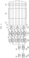
- FIG. 4 is a view illustrating a configuration of a system for coating multi-division dual layers according to an embodiment of the present invention.
- a system including a flow rate control apparatus 200 may include tanks 300, pumps 290, valves 260, flowmeters 250, a plurality of slot dies 310, densitometers 240, and a drying furnace 320.
- the system supplies slurry accommodated in the tanks 300 according to driving of the pumps 290 to coat an electrode of a secondary battery with the slurry.
- a dual layer method in which an upper layer and a lower layer are divided and individually operated may be used in the system.
- the system in which a plurality of rows are formed in an upper portion and a plurality of rows are formed in a lower portion in the same manner may perform coating on the electrode through a multi-division method.
- the flow rate control apparatus 200 may control the pumps 290 to supply the slurry from the tanks 300
- a first pump 291 is included in the upper layer to supply the slurry to the upper layer from a first tank 301 of the upper layer.
- a second pump 292 of the lower layer supplies the slurry of a second tank 302 of the lower layer to the lower layer.
- the processor 210 may control valves 261, 263, and 265 of the upper layer to supply the same amounts of the slurry to the rows on the upper layer including the slot dies 310 of the plurality of rows.
- the processor 210 may control valves 262, 264, and 266 of the lower layer to supply the same amounts of the slurry to the rows on the lower layer including the slot dies 310 of the plurality of rows.
- the processor 210 controls a plurality of valves 260 to control an amount of the slurry and measures flow rates of the slurry for the plurality of rows of the upper layer using a plurality of flowmeters 251, 253, and 255.
- the processor 210 may measure flow rates of the slurry for the rows of the lower layer using a plurality of flowmeters 252, 254, and 256.
- the processor 210 may feedback-control the valves 260 on the basis of the measured flow rates for the plurality of rows. In addition, the processor 210 may calculate an amount of the slurry supplied through the pumps 290 on the basis of the sum of the flow rates for the plurality of rows to control RPM of the pumps 290.
- the processor 210 may control the pump 290 to reduce the amount of the slurry when a total amount of the slurry for each layer is so large, and control the pump 290 of the corresponding layer to increase the amount of the slurry when the amount of the slurry is insufficient.
- the processor 210 may control the valves 260 to reduce the differences between the flow rates of the slurry in the rows on the basis of flow rate values for the plurality of rows. For example, the processor 210 may increase an opening degree of a valve for a row of which a flow rate is insufficient and decrease an opening degree of a valve for a row of which a flow rate is so high.
- the processor 210 may measure coating thicknesses using the densitometers 240 and obtain data for a width direction and a moving direction of the electrode.
- the processor 210 calculates an amount of the slurry for each layer, measures an amount of the slurry for each row of the layers in real time, and controls the pumps 290 and the valves 260 to uniformly distribute amounts of the slurry to the plurality of rows.
- the processor 210 may measure data on a flow rate of the slurry actually flowing through each of the rows for each row or layer using the flowmeters 250 installed on the plurality of rows.
- the processor 210 may input a control command to any one layer to adjust balance of the flow rate of the slurry between the upper layer and the lower layer.
- the processor 210 may obtain electrode coating amounts and dispersions for each of the rows on the basis of data of the flowmeters 250 and data of the densitometers 240, and thus may measure a total loading level (hereinafter, L/L) per unit area or a thickness to obtain data on the width direction and the moving direction.
- L/L total loading level
- FIG. 5 is a view illustrating an operation flow of the flow rate control apparatus for coating multi-division dual layers according to an embodiment of the present invention.
- the processor 210 may use the pumps 290 and the valves 260 to control flow rates for the plurality of rows formed on an upper layer A and a lower layer B. Accordingly, the processor 210 automatically controls flow rates of the slurry so that the electrode is coated with a set or predetermined thickness.
- the processor 210 drives the pumps 290 for the upper layer A and the lower layer B.
- the processor 210 may drive the first pump 291 of the upper layer A (S210) and the second pump 292 of the lower layer B (S215).
- the processor 210 may control the plurality of valves 261, 263, and 265 of the upper layer A (S220) and control the plurality of valves 262, 264, and 266 of the lower layer B (S225) so that the slurry is distributed and supplied to the plurality of rows.
- the processor 210 calculates flow rates for the plurality of rows of the upper layer A and the lower layer B on the basis of flow rate data measured by the plurality of flowmeters 250.
- the processor 210 measures flow rates for the plurality of rows of the upper layer A using the plurality of flowmeters 251, 253, and 255 (S230). In addition, the processor 210 may measure flow rates for the rows of the lower layer using the plurality of flowmeters 252, 254, and 256 (S235).
- the processor 210 may control flow rates for the rows by controlling the valves 260 on the basis of the flow rates measured by the flowmeters 250 (S240).
- the processor 210 may control the valves according to the flow rates for the upper layer A and the lower layer B to reduce a difference in flow rate between the rows.
- the processor 210 may compare an average value of all flow rates for coating in each row and a target flow rate value on the basis of the flow rates of the slurry to control the pumps 290 according to a difference therebetween.
- the processor 210 may calculate a total amount of the slurry for the upper layer A and the lower layer B on the basis of data measured by the plurality of flowmeters 250 and control the pumps 290 on the basis of the calculated sum to control amounts of the slurry supplied from the tanks 300.
- the processor 210 may adjust the RPM of the pumps 290 to adjust a total amount of the slurry supplied to the upper layer A and the lower layer B.
- the processor 210 may compare a flow rate of the upper layer A and a flow rate of the lower layer B to control a ratio thereof (S250).
- the processor 210 may compare the flow rate of the upper layer A and the flow rate of the lower layer B to control the pumps 290 on the basis of a result thereof.
- the processor 210 may calculate a dispersion of coating amounts for each row using the flowmeters 250 and feedback-control the valves 260.
- the processor 210 may determine opening degrees of the valves 260 installed in the rows on the basis of the calculated dispersion to automatically adjust flow rates of the slurry (S260).
- the processor 210 compares an L/L per unit area and a total thickness, which are measured by the densitometers 240 or thickness measurement devices, and the sum of the flow rates of the upper layer A and the lower layer B to compensate for different values.
- the processor 210 may input a control command for total flow rates for the rows to the valves of the upper layer and the valves of the lower layer to control the total flow rates for the rows.
- the processor 210 may compensate for a difference in the flow rates of the layers to eliminate an error according to a measurement method.
- FIG. 6 is a flow diagram illustrating a flow rate control method for coating multi-division dual layers according to an embodiment of the present invention.
- the processor 210 may measure L/Ls per unit area or coating thicknesses using the densitometers 240.
- the processor 210 may calculate a total average L/L and a total average thickness for the plurality of rows.
- the processor 210 may calculate averages for three rows of the upper layer A and for three rows of the lower layer B.
- the processor 210 determines whether the L/L and the thickness satisfy target values (S320).
- the processor 210 may determine that an amount of the slurry for coating is insufficient and control the RPM of at least one of the pumps 291 and 292 of the upper layer A and the lower layer B (S340).
- the processor 210 compares the sum of measured values of the flowmeters of the upper layer A and the sum of measured values of the flowmeters of the lower layer B for each slot die to determine whether a ratio thereof satisfies a set value (S330).
- the processor 210 may control the RPM of at least one of the pumps 291 and 292 of the upper layer A and the lower layer B (S340).
- the processor 210 may control a flow rate and the pumps 290 in conjunction with each other.
- the processor 210 determines whether values of the flowmeters of each row of the lower layer are the same (S350).
- the processor 210 proportionally controls the plurality of valves 260 for the lower layer (S360).
- the processor 210 may determine whether L/Ls and thicknesses for each row are the same (S370). When the L/Ls and the thicknesses for each row are the same, the processor 210 may proportionally control the valves 260 of the upper layer A (S380).
- the processor 210 may repeatedly perform the proportional control on the valves 260 until a condition is satisfied.
- the processor 210 may control a flow rate and the valves 260 in conjunction with each other.
- the processor 210 may stop a coating control in any one case of a case in which measured values of the flowmeter 250 of each row are the same or a case in which the L/Ls and the thicknesses for each row are the same.
- FIG. 7 is a table showing pump control standard values of the flow rate control apparatus for coating multi-division dual layers according to an embodiment of the present invention.
- the processor 210 may control the flowmeters 250 and the pumps 290 in conjunction with each other.
- the processor 210 may measure amounts of the slurry supplied to the slot dies 310 using the flowmeters 250 and control the pumps 290 according to measured flow rate values on the basis of the linked control algorithm.
- the slurry supplied to the slot dies 310 passes through the flowmeters 250, moves in the moving direction, and coats the electrode.
- the processor 210 may calculate coating amounts on the basis of the flow rates measured by the flowmeters 250. Accordingly, the processor 210 may analyze the amounts of the slurry supplied to the slot dies 310, the flow rates measured by the flowmeters 250, and the coating amounts measured by the densitometers 240 in conjunction with each other.
- the processor 210 may calculate an average flow rate value of the flow rates for each row. When the average flow rate value is smaller than a target flow rate value, the processor 210 may control the pump 290 to increase a supply amount of the slurry, and when the average flow rate value is greater than the target flow rate value, the processor 210 may control the pump 290 to reduce the supply amount of the slurry.
- the processor 210 may calculate an average of coating amounts (thicknesses) for each row and calculate a flow rate value to reach a target coating amount to control the pump 290.
- the processor 210 may repeatedly perform an experiment to standardize the RPM of the pump 290.
- the processor 210 may set the RPM of the pump 290 with reference to FIG. 7 and repeatedly perform a process of changing the RPM of the pump 290 according to the flow rate value and the thickness to obtain the target flow rate value.
- the processor 210 may store a setting of the pump 290 for satisfying the target flow rate value in the memory 220.
- the processor 210 may obtain data for an amount of a change in the RPM of the pump on the basis of an amount of a change calculated by subtracting a target flow rate from a flow rate average in the moving direction.
- the processor 210 may classify amounts of a change into a plurality of levels (may be changed as necessary) to set an amount of change in the RPM of the corresponding pump. In this case, since a difference in amount of change in the RPM may vary according to properties of the slurry used as a coating agent, an optimal corresponding value for each type of slurry may be found through an experiment.
- FIG. 8 is a table showing standard values for opening degrees of valves of the flow rate control apparatus for coating multi-division dual layers according to an embodiment of the present invention.
- the processor 210 may control the valves 260 in conjunction with measured values of the flowmeters 250.
- the processor 210 may group one slot die 310, one flowmeter 250, and one valve 260 and calculate a dispersion of coating amounts for each slot die.
- the processor 210 may control opening degrees of the valves on the basis of the calculated dispersions according to a range of the dispersions as in FIG. 8 .
- the controlling of the opening degree of the valve 260 may change a flow rate of the slurry for the slot die 310, and a coating amount of the electrode may be changed according to a change in flow rate of the slurry.
- the processor 210 may repeatedly adjust the opening degree of the valve according to the dispersion to calculate an opening degree of the valve satisfying a target coating amount. In this case, an optimum value for each type of slurry may be found because there may be changes in valve adjustment and coating amount according to the type of slurry.
- FIG. 9 shows graphs of dispersions of flow rates and thicknesses according to the operation of a pump of the flow rate control apparatus for coating multi-division dual layers according to an embodiment of the present invention.
- the processor 210 may calculate dispersions of coating amounts according to the RPM of the pumps 290 and flow rates measured by the flowmeters 250 and analyze a correlation between the RPM of the pumps 290 and the flow rates.
- a relationship between the RPM of the pumps 290 and the flow rates has a linear characteristic (e.g., the flow rates may be linearly proportional to the RPM of the pumps 290).
- a measurement deviation for flow rates changed according to the RPM of the pump 290 may be checked.
- the deviation is a deviation between a maximum value and a minimum value when measured a number of times (e.g., three times).
- the processor 210 may control a flow rate in an actual use range D1 which is a case in which a lowest deviation is calculated and the RPM of the pump 290 is 180 and 210.
- the processor 210 may control flow rates for the plurality of slot dies 310 of the upper layer A and the lower layer B.
- FIG. 10 shows graphs of flow rate control results of the flow rate control apparatus for coating multi-division dual layers according to an embodiment of the present invention.
- the processor 210 supplies the slurry to the upper layer A and the lower layer B, distributes the slurry to the plurality of rows, and measures flow rates of the slurry using the flowmeters 250.
- the processor 210 may calculate a dispersion of the flow rates in the lower layers B.
- the processor 210 may calculate a dispersion in the rows of the upper layer A and the lower layer B.
- the processor 210 may verify a flow rate control within a flow rate dispersion of ⁇ 0.2% in the lower layer B and a flow rate dispersion of ⁇ 0.5% in the upper layer A and the lower layer B.
- the processor 210 may control the pumps 290 and the valves 260 according to flow rates to reduce a dispersion to reach a target coating amount.
- the flow rate control apparatus and method for coating multi-division dual layers can stabilize a process of coating the electrode through a method of coating multi-division dual layers by adjusting amounts of the slurry for the rows through the valves while adjusting supply amounts of the slurry through the pumps, adjusting the pumps and the valves on the basis of flow rates measured by the flowmeters, and calculating opening degrees of the pumps and the valves to correspond to target coating amounts and can improve quality thereof by uniformly controlling coating amounts.
- the present invention described in this specification can be implemented through, for example, a method, a process, an apparatus, a software program, a data stream, or a signal. Even when the present invention is described as being implemented in only a single form (for example, as the method), the described features may be implemented in another form (for example, as the apparatus or program).
- the apparatus may be implemented using proper hardware, software, firmware, or the like.
- the method may be implemented in an apparatus such as a processor which generally refers to a processing device such as a computer, a microprocessor, an integrated circuit, and a programmable logic device.
- the processor includes a communication device such as a computer, a cell phone, a portable/personal digital assistant (PDA) terminal, and other devices which facilitate information communication between final users.
- PDA portable/personal digital assistant
- the processor may be implemented as a CPU, system on chip (SoC), or the like, may drive an operating system or application to control a plurality of hardware or software components connected to the processor, and may perform various data processing and operations.
- the processor may be configured to execute at least one command stored in the memory (not shown) and store result data of the execution in the memory.
- a flowmeter capable of measuring an actual flow rate is installed in each slot die through which a slurry is supplied, a coating amount of each of the slot dies in a plurality of rows of an upper layer and a lower layer is measured to adjust a supply amount of the slurry, and thus coating quality can be easily evaluated, and also the coating quality can be improved (e.g., increased).
- a flow rate can be measured to check a coating amount in real time and a slurry is supplied in a plurality of rows using few pumps to perform a feedback-control according to flow rates, an electrode coating process can be stabilized.
- the present invention because the number of tanks and pumps for supplying a slurry is decreased to simplify a structure, a process can be more easily performed, and a manufacturing cost can be reduced.
Landscapes
- Chemical & Material Sciences (AREA)
- Engineering & Computer Science (AREA)
- Manufacturing & Machinery (AREA)
- Chemical Kinetics & Catalysis (AREA)
- Electrochemistry (AREA)
- General Chemical & Material Sciences (AREA)
- Physics & Mathematics (AREA)
- Fluid Mechanics (AREA)
- Analytical Chemistry (AREA)
- Battery Electrode And Active Subsutance (AREA)
Abstract
The present invention relates to a flow rate control apparatus (200) and method for coating multi-division dual layers. A flow rate control apparatus (200) according to the present invention includes a plurality of slot dies (310, 311) which are formed as an upper layer (A) and a lower layer (B) and coat an electrode with slurry, a pump (290, 291, 292) which supplies the slurry from a tank (300) to each of the upper layer (A) and the lower layer (B), a valve (260, 261, 262, 263, 264, 265, 266) which is installed in the plurality of slot dies (310, 311), divides the slurry supplied from the pump (290, 291, 292), and supplies the divided slurry to the plurality of slot dies (310, 311), a flowmeter (250, 251, 252, 253, 254, 255, 256) which measures a flow rate of the slurry supplied to the plurality of slot dies (310, 311), and a processor (210) which controls the pump (290, 291, 292) and the valve (260, 261, 262, 263, 264, 265, 266) on the basis of the flow rate of the slurry measured by the flowmeter (250, 251, 252, 253, 254, 255, 256) to control a coating amount of the electrode.
Description
- Aspects of embodiments of the present disclosure relate to a flow rate control apparatus for coating multi-division dual layers which controls a flow rate of the slurry for coating an electrode, and a flow rate control method for the same.
- A secondary battery is a battery that can be charged and discharged, unlike a primary battery that cannot be recharged. Low-capacity secondary batteries are used in small portable electronic devices such as smartphones, feature phones, notebook computers, digital cameras, and camcorders, and high-capacity secondary batteries are widely used as driving power sources and power storage batteries for motors in hybrid and electric vehicles. Such a secondary battery includes an electrode assembly provided with a positive electrode and a negative electrode, a case for accommodating the electrode assembly, electrode terminals connected to the electrode assembly, and the like.
- Manufacturing such a secondary battery involves a process of coating a positive and negative electrode substrate with an active material slurry.
- An electrode may be coated through a method of supplying slurry accommodated in a tank to a slot die using a pump and coating the electrode with the slurry discharged through the slot die.
- A drying process is performed on the coated electrode (e.g., electrode plate) while the coated electrode passes through a drying furnace, and coating quality of the electrode plate passed through the drying furnace is measured and managed in a width direction and a movement direction of the electrode using a loading level (hereinafter, L/L) per unit area measured by a densitometer.
- However, in a system for coating an electrode, when a width of a slot die is increased to improve productivity, a large number of coating rows can be produced at the same time, but there is a problem of degrading the coating quality such as an increase in dispersion of the L/L per unit area in the width direction or the like.
- In addition, in the system for coating an electrode, when a coating thickness is increased, there is a problem of degrading the quality of the electrode such as a decrease in bonding force between the electrode and a slurry after drying, a decrease in conductivity of ions due to binders concentrated in an upper portion, or the like.
- Accordingly, a method of improving both the quality and productivity of an electrode is desired.
- The above-described information described in the background technology of the present invention is only to facilitate understanding of the background of the present invention and can also have information not included in the conventional technology.
- The present invention is directed to providing a flow rate control apparatus and method for coating multi-division dual layers in which dual layers divided into a plurality of parts controls a flow rate of a slurry to adjust a coating amount of an electrode of a secondary battery and improve coating quality.
- However, technical objectives to be solved by the present invention are not limited to the above-described objective, and other objectives which are not described above will be clearly understood by those skilled in the art through the following description.
- According to an aspect of the present invention, there is provided a flow rate control apparatus for coating multi-division dual layers, the flow rate control apparatus including: a plurality of slot dies which are formed as an upper layer and a lower layer and coat an electrode with a slurry; a pump which supplies the slurry from a tank to each of the upper layer and the lower layer; a valve which is installed in (or at) the plurality of slot dies, divides the slurry supplied from the pump, and supplies the divided slurry to the plurality of slot dies; a flowmeter which measures a flow rate of the slurry supplied to the plurality of slot dies; and a processor which controls the pump and the valve on the basis of the flow rate of the slurry measured by the flowmeter to control a coating amount of the electrode.
- The valve may be provided as a plurality of valves. The slurry to be supplied to the upper layer may be supplied through the pump to the plurality of slot dies of the upper layer. The slurry to be supplied to the lower layer may be supplied through the pump to the plurality of slot dies of the lower layer.
- The pump may include a first pump which supplies the slurry accommodated in the tank to the upper layer; and a second pump which supplies the slurry to the lower layer.
- The processor may receive the flow rate for each of the plurality of slot dies using the flowmeter and may compare a sum of flow rates for the upper layer and a sum of flow rates for the lower layer. When a ratio between the sums of the flow rates for the layers does not reach a target value, the processor may control revolutions per minute (RPM) of the pump to adjust a supply amount of the slurry being supplied to any one of the upper layer and the lower layer.
- The processor may compare the flow rates for the plurality of slot dies included in the lower layer. When there is a difference in flow rate for the plurality of slot dies between rows, the processor may control the valve to reduce the difference in flow rate of the slurry for the plurality of slot dies.
- When the coating amount of the electrode measured by a densitometer does not satisfy a target coating amount, the processor may control the pump to adjust a supply amount of the slurry.
- The flow rate control apparatus may further include a densitometer to measure a thickness of a coating amount of the electrode.
- The processor may calculate a difference in coating amount for the plurality of slot dies between rows measured using a densitometer. When there is the difference in coating amount for the plurality of slot dies between the rows, the processor may control the valve to adjust a flow rate of the slurry supplied to the plurality of slot dies.
- The processor may calculate an average of the flow rates for the plurality of slot dies of rows measured by the flowmeter. The processor may further calculate an amount of change by subtracting a target flow rate from an average value of the flow rates and may set an amount of change in revolutions per minute (RPM) of the pump according to a range of the amount of change.
- The processor may calculate a total average of the flow rates measured by the flowmeter, calculates a dispersion using values by subtracting flow rates of the rows from the total average, and adjusts an opening degree of the valve according to a size of the dispersion.
- According to another aspect of the present invention, there is provided a flow rate control method for coating multi-division dual layers, including: supplying, by a pump, a slurry for coating an electrode to an upper layer and a lower layer of a slot die from a tank; dividing, by a valve, the slurry supplied from the pump and supplying the divided slurry to a plurality of slot dies of the upper layer and the lower layer; measuring, by a flowmeter, flow rates of the slurry supplied to the plurality of slot dies; and changing, by a processor, a flow rate of the slurry supplied to any one of the plurality of slot dies by controlling at least any one of the pump and the valve on the basis of the flow rates of the slurry measured by the flowmeter.
- The supplying of the slurry may include: supplying, by a first pump, the slurry accommodated in the tank to the upper layer; and supplying, by a second pump, the slurry to the lower layer.
- The dividing of the slurry and supplying of the divided slurry may include dividing, by a valve installed at the upper layer, the slurry to be supplied to the upper layer and supplying the divided slurry to the plurality of slot dies provided in the upper layer; and dividing, by a valve installed at the lower layer, the slurry to be supplied to the lower layer and supplying the divided slurry to the plurality of slot dies provided in the lower layer.
- The changing of the flow rate of the slurry may include: receiving each of the flow rates for the plurality of slot dies through the flowmeter and comparing a sum of the flow rates for the upper layer and a sum of the flow rates for the lower layer; determining whether a ratio between the sums of the flow rates for the layers reaches a target value according to a comparison result; and controlling revolutions per minute (RPM) of the pump to adjust a supply amount of the slurry supplied to any one of the upper layer and the lower layer when the ratio between layers to the sum of the flow rates does not reach the target value.
- The changing of the flow rate of the slurry may include: comparing the flow rates for the plurality of slot dies included in the lower layer; and controlling the valve to reduce a difference in flow rate of the slurry for the plurality of slot dies when there is the difference in flow rate between rows of the plurality of slot dies as a result.
- The changing of the flow rate of the slurry may include: calculating averages of the flow rates for the plurality of slot dies for rows measured by the flowmeter; calculating an amount of change by subtracting a target flow rate from average values of the flow rates; and setting an amount of change of revolutions per minute (RPM) of the pump according to a range of the amount of change.
- The changing of the flow rate of the slurry may include: calculating a total average of the flow rates measured by the flowmeter; calculating a dispersion using values calculated by subtracting flow rates for rows from the total average; and adjusting an opening degree of the valve according to a size of the dispersion.
- The flow rate control method may further include measuring, by a densitometer, a thickness of a coating amount for the electrode.
- The flow rate control method may further include: comparing, by the processor, the coating amount for the electrode measured by a densitometer and a target coating amount; and controlling, by the processor, the pump to adjust a supply amount of the slurry when the coating amount of the electrode does not satisfy the target coating amount.
- The flow rate control method may further include: calculating, by the processor, a difference in coating amount between rows for the plurality of slot dies measured by a densitometer; and controlling, by the processor, the valve to adjust flow rates of the slurry supplied to the plurality of slot dies when there is a difference in coating amount between rows for the plurality of slot dies.
- All embodiments described in this specification may be advantageously combined with one another to the extent that their respective features are compatible. In particular, the expressions "according to an embodiment," "in an embodiment," "an embodiment of the invention provides" etc. mean that the respective features may or may not be part of specific embodiments of the present invention.
- The following drawings attached to this specification illustrate embodiments of the present disclosure, and further describe aspects and features of the present disclosure together with the detailed description of the present disclosure. Thus, the present disclosure should not be construed as being limited to the drawings:
-
FIGS. 1 and2 are, respectively, a schematic and a block diagram illustrating a cylindrical battery; -
FIG. 3 is a schematic block diagram illustrating a flow rate control apparatus for coating multi-division dual layers according to an embodiment of the present invention; -
FIG. 4 is a view illustrating a configuration of a system for coating multi-division dual layers according to an embodiment of the present invention; -
FIG. 5 is a view illustrating an operation flow of the flow rate control apparatus for coating multi-division dual layers according to an embodiment of the present invention; -
FIG. 6 is a flow diagram illustrating a flow rate control method for coating multi-division dual layers according to an embodiment of the present invention; -
FIG. 7 is a table showing pump control standard values of the flow rate control apparatus for coating multi-division dual layers according to an embodiment of the present invention; -
FIG. 8 is a table showing standard values for opening degrees of valves of the flow rate control apparatus for coating multi-division dual layers according to an embodiment of the present invention; -
FIG. 9 shows graphs of dispersions of flow rates and thicknesses according to the operation of a pump of the flow rate control apparatus for coating multi-division dual layers according to an embodiment of the present invention; and -
FIG. 10 shows graphs of flow rate control results of the flow rate control apparatus for coating multi-division dual layers according to an embodiment of the present invention. - Hereinafter, exemplary embodiments of the present invention will be described in detail with reference to the accompanying drawings. First, terms and words used in the present specification and claims should not be interpreted as being limited to commonly used meanings or meanings in dictionaries and should be interpreted as having meanings and concepts which are consistent with the technological scope of the present invention based on the principle that the inventors have appropriately defined concepts of the terms in order to describe the present invention in the best way. Therefore, because the embodiments described in this specification and components illustrated in the drawings are only some exemplary embodiments and do not represent the overall technological scope of the present invention, it should be understood that there may be various equivalents or modifications substituting the exemplary embodiments at the time of filing of this application. In addition, the terms "comprise," "include," "comprising," and/or "including" used herein specify some stated shapes, numbers, steps, operations, members, elements, and/or presence of groups thereof but do not preclude one or more other shapes, numbers, operations, members, elements, and/or presence or addition of groups thereof. In addition, when the embodiments of the present invention are described, the terms "may" or "may be" may include "one or more embodiments of the present invention."
- In addition, in order to facilitate understanding of the present invention, the accompanying drawings are not drawn to scale, and dimensions of some components may be exaggerated. In addition, like reference numerals may be assigned to like elements in different embodiments.
- The expression "two comparative objects are the same" means "the two comparative objects are actually the same." Therefore, the term "actually the same" includes a case in which there is a deviation considered as a low level in the art, for example, a deviation of 5% or less. In addition, the description "some parameters are uniform within a certain region" may mean that "some parameters are uniform in an average viewpoint."
- Although terms such as first, second, or the like may be used for describing various elements, the elements are not limited by the terms. These terms are only used to distinguish one element from another element, and unless otherwise specifically described, a first element may also be a second element.
- Throughout the specification, unless specifically described otherwise, each element may be singular or a plurality.
- A case in which a first element is disposed "above (or under)" or "on (or below)" a second element may include a case in which the first element is disposed to be in contact with an upper (or lower) surface of the second element or a case in which a third element may be interposed between the first element and the second element disposed above (or under) the first element.
- It should be understood that, when a first element is referred to as being "connected," "coupled," or "bonded" to a second element, although the first element may be directly connected or bonded to the second element, it should be understood that a third element may be interposed therebetween, or the elements may be connected, coupled, or bonded through other elements. In addition, when a first part is referred to as being "electrically connected" to a second part, it includes not only a case in which the first part is "directly connected" to the second part but also a case in which the first part is "connected" to the second part with a third element interposed therebetween.
- Throughout the specification, unless otherwise specifically described, "A and/or B" means "A," "B," or "A and B." That is "and/or" includes all combinations or any combination of a plurality of listed items. Unless otherwise specifically described, "C to D" means "more than or equal to C and less than or equal to D."
-
FIGS. 1 and2 are, respectively, a schematic and a block diagram illustrating a cylindrical battery. - Referring to
FIGS. 1 and2 , a cylindrical lithium-ionsecondary battery 100 according to various embodiments of the present invention may include acylindrical can 110, anelectrode assembly 120, and acap assembly 140. In addition, the cylindrical lithium-ionsecondary battery 100 may further include acenter pin 130 in some cases. In addition, in thesecondary battery 100 according to the embodiment of the present invention, since thecap assembly 140 serves to interrupt a current, thecap assembly 140 may be referred to as a current interrupt device in some cases. - The cylindrical can 110 may include a
bottom portion 111 having a substantially circular shape and acylindrical sidewall 112 extending upward from a circumferential portion of thebottom portion 111 to a set or predetermined length. During a manufacturing process of the secondary battery, an upper portion of thecylindrical can 110 is open. Accordingly, during an assembly process of the secondary battery, theelectrode assembly 120 and thecenter pin 130 along with an electrolyte may be inserted into thecylindrical can 110. For example, the cylindrical can 110 may be formed of steel, stainless steel, aluminum, aluminum alloy, and/or an equivalent material thereof but is not limited thereto. - In addition, the cylindrical can 110 may include a
beading part 113 disposed below thecap assembly 140 to be recessed inward and a crimpingpart 114 disposed above thecap assembly 140 to be bent inward such that thecap assembly 140 does not escape to the outside, wherein thebeading part 113 and the crimpingpart 114 are disposed around thecap assembly 140. - The
electrode assembly 120 may be accommodated in thecylindrical can 110. Theelectrode assembly 120 may include anegative electrode plate 121 in which a negative current collector plate is coated with a negative active material (for example, graphite, carbon, or the like), apositive electrode plate 122 in which a positive current collector plate is coated with a positive active material (for example, a transition metal oxide such as LiCoO2, LiNiO2, LiMn2O4, and/or the like), and aseparator 123 positioned between thenegative electrode plate 121 and thepositive electrode plate 122 to prevent a short circuit and allow only lithium-ions to move. In addition, thenegative electrode plate 121, thepositive electrode plate 122, and theseparator 123 may be wound in a substantially cylindrical shape. In this case, for example, the negative current collector plate may be manufactured of a copper (Cu) foil and/or the like, and the positive electrode current collector plate may be formed of an aluminum (Al) foil and/or the like, and the separator may be formed of polyethylene (PE), polypropylene (PP) and/or the like, but the present invention is not limited thereto. - In addition, a
negative tab 124 protruding downward to extend to a set or predetermined length may be welded to thenegative electrode plate 121, and thepositive tab 125 protruding upward to extend to a set or predetermined length may be welded to thepositive electrode plate 122, but the opposite is possible. In addition, for example, thenegative tab 124 may be formed of copper (Cu), nickel (Ni), and/or the like, and thepositive tab 125 may be formed of aluminum (Al), but the present invention is not limited thereto. - In addition, the
negative tab 124 of theelectrode assembly 120 may be welded to thebottom portion 111 of thecylindrical can 110. Accordingly, the cylindrical can 110 may operate as a negative electrode. However, conversely, thepositive tab 125 may be welded to thebottom portion 111 of thecylindrical can 110, and in this case, the cylindrical can 110 may operate as a positive electrode. - In addition, a first insulating
plate 126 which is coupled to thecylindrical can 110 and in which afirst hole 126a is formed at a center thereof and asecond hole 126b is formed at an outer side thereof may be interposed between theelectrode assembly 120 and thebottom portion 111. The first insulatingplate 126 serves to prevent theelectrode assembly 120 from coming into electrical contact with thebottom portion 111 in thecylindrical can 110. Particularly, the first insulatingplate 126 serves to prevent thepositive electrode plate 122 in theelectrode assembly 120 from coming into electrical contact with thebottom portion 111. In this case, thefirst hole 126a serves to allow the gas to quickly move upward through thecenter pin 130 when a large amount of gas is generated due to abnormality of the secondary battery, and thesecond hole 126b serves to allow thenegative tab 124 to pass therethrough and be welded to thebottom portion 111. - In addition, a second insulating
plate 127 which is coupled to thecylindrical can 110 and in which afirst hole 127a is formed at a center thereof and a plurality ofsecond holes 127b are formed at an outer side thereof may be interposed between theelectrode assembly 120 and thecap assembly 140. The second insulatingplate 127 serves to prevent theelectrode assembly 120 from coming into electrical contact with thecap assembly 140. Particularly, the second insulatingplate 127 serves to prevent thenegative electrode plate 121 in theelectrode assembly 120 from coming into electrical contact with thecap assembly 140. In this case, thefirst hole 127a serves to allow the gas to quickly move to thecap assembly 140 when a large amount of gas is generated due to abnormality of the secondary battery, and thesecond holes 127b serve to allow thepositive tab 125 to pass therethrough and be welded to thecap assembly 140. In addition, the remainingsecond holes 127b serve to allow the electrolyte to quickly flow into theelectrode assembly 120 in an electrolyte injection process. - In addition, diameters of
first holes plates center pin 130 so that thecenter pin 130 does not come into electrical contact with thebottom portion 111 of the cylindrical can 110 or thecap assembly 140 when an external impact is applied thereto. - The
center pin 130 may have a hollow circular pipe shape and may be coupled to substantially a center of theelectrode assembly 120. For example, thecenter pin 130 may be formed of steel, stainless steel, aluminum, aluminum alloy, polybutylene terephthalate, and/or the like, but is not limited thereto. Thecenter pin 130 serves to suppress deformation of theelectrode assembly 120 during charging or discharging of the battery and serves as a moving passage of gas generated in the secondary battery. However, thecenter pin 130 may be omitted in some cases. - The
cap assembly 140 may include atop plate 141, amiddle plate 142, an insulatingplate 143, and abottom plate 144. - The
middle plate 142 may be positioned under thetop plate 141 and may have a substantially flat shape. - When viewed from below, the insulating
plate 143 may be formed in a circular ring shape having a set or predetermined width. In addition, the insulatingplate 143 serves to insulate themiddle plate 142 and thebottom plate 144 from each other. For example, the insulatingplate 143 may be interposed between and ultrasonically welded to themiddle plate 142 and thebottom plate 144 but is not limited thereto. - Although the present invention has been described with the example of the cylindrical secondary batter, the present invention may be applied to any secondary battery including an electrode.
-
FIG. 3 is a schematic block diagram illustrating a flow rate control apparatus for coating multi-division dual layers according to an embodiment of the present invention. - A flow rate control apparatus 200 for coating multi-division dual layers (hereinafter, flow rate control apparatus) may adjust an amount of the slurry for coating electrode in a system for coating the electrode of the secondary battery.
- Referring to
FIG. 3 , the flow rate control apparatus 200 according to an embodiment of the present invention may include amemory 220, acommunication part 230, an input part 170, anoutput part 180, adensitometer 240, aflowmeter 250, avalve 260, apump 290, and aprocessor 210. - The
densitometer 240 may measure a coating amount (thickness) on the basis of a density of coated slurry. A separate thickness measurement device may be used as thedensitometer 240. - The
densitometer 240 may be installed on each of a front end and a rear end of a drying furnace (not shown) and may measure the coating amount (thickness). - The
densitometer 240 may obtain density data or thickness data for a width direction and a moving direction. Thedensitometer 240 inputs the obtained data to theprocessor 210. - The
flowmeter 250 measures a flow rate of the slurry moved by thepump 290. Theflowmeter 250 measures an amount of the slurry with which the electrode is coated and inputs the measured amount to theprocessor 210. - The
flowmeter 250 may be installed on each of a plurality of rows of a plurality of slot dies. Theflowmeter 250 may be installed on each of an upper layer and a lower layer of the plurality of rows. - The
valve 260 divides the slurry supplied through thepump 290 and supplies the divided slurry to the slot dies of the plurality of rows. - The
valve 260 may adjust an amount of the slurry to be supplied. An automatic valve may be used as thevalve 260. Thevalve 260 adjusts an amount of the slurry by adjusting an opening degree thereof according to a control command of theprocessor 210. - The
pump 290 supplies the slurry from a tank in which the slurry is accommodated to a system for coating electrode. Onepump 290 may be installed on one tank. - The
memory 220 may store density data or thickness data input from thedensitometer 240 and flow rate data of the slurry input from theflowmeter 250. Thememory 220 may store data of an opening degree of thevalve 260 and revolutions per minute (RPM) of thepump 290. In addition, thememory 220 may store feedback data of thedensitometer 240 and store set data for controlling thepump 290 and thevalve 260 on the basis of the feedback data. - The
memory 220 may store data about a flow rate control algorithm, a coating amount control algorithm, a thickness measurement algorithm, a pump control algorithm, a linked control algorithm, a valve control algorithm, and the like. - The
memory 220 may include a storage medium such as a random-access memory (RAM), a non-volatile memory such as read-only memory (ROM) and an electrically erasable programmable ROM (EEPROM), a flash memory, a hard disc drive (HDD), a solid-state drive (SSD), a solid disc drive (SDD), and/or the like. - The
communication part 230 transmits and receives data to and from theprocessor 210, thememory 220, thedensitometer 240, theflowmeter 250, thevalve 260, thepump 290, theinput part 270, and theoutput part 280. In addition, thecommunication part 230 may transmit and receive data to and from an external terminal or server. - The
communication part 230 supports at least one among near field communication such as Ethernet, WiFi, and Bluetooth, mobile communication, serial communication, and/or the like. - The
input part 270 may receive data for flow rate control. In addition, theinput part 270 may receive a user command according to flow rate control. Theinput part 270 may include at least one among at least one button, a switch, and a touchpad. - The
processor 210 may include at least one micro-processor and operate on the basis of the algorithms and data stored in the memory 22. - The
processor 210 controls thepump 290 to supply the slurry for coating electrode from the tank and to adjust a supply amount of the slurry and controls thevalve 260 to adjust an amount of the slurry supplied to each of the slot dies of the plurality of rows. - The
processor 210 supplies the slurry from one tank through onepump 290, and the slurry to be supplied is divided and supplied to the slot dies of the plurality of rows. - The
processor 210 may monitor an amount of the slurry for each of the plurality of rows on the basis of data measured by theflowmeter 250 and control thevalve 260 in respond to the monitored amount. - The
processor 210 may control thevalve 260 installed on each of the plurality of rows. - In addition, the
processor 210 may measure a flow rate of the slurry controlled by thevalve 260 through theflowmeter 250. Theprocessor 210 may measure flow rates of the slurry for the upper layer and the lower layer of the plurality of rows through a plurality offlowmeters 250 installed on the slot dies of the plurality of rows. - The
processor 210 may receive the flow rates of the slurry for the slot dies of the plurality of rows measured by theflowmeters 250 and data ofdensitometers 240 connected to an upper end and a lower end of the drying furnace to feedback-control the pump 290 (e.g., control thepump 290 using feedback). In addition, theprocessor 210 may feedback-control the valve 260 (e.g., control thepump 290 using feedback). - The
processor 210 may adjust a coating amount of the electrode by continuously feedback-controlling thepump 290 and thevalve 260. -
FIG. 4 is a view illustrating a configuration of a system for coating multi-division dual layers according to an embodiment of the present invention. - Referring to
FIG. 4 , a system including a flow rate control apparatus 200 may includetanks 300, pumps 290,valves 260,flowmeters 250, a plurality of slot dies 310,densitometers 240, and a dryingfurnace 320. - The system supplies slurry accommodated in the
tanks 300 according to driving of thepumps 290 to coat an electrode of a secondary battery with the slurry. - In this case, a dual layer method in which an upper layer and a lower layer are divided and individually operated may be used in the system. In addition, the system in which a plurality of rows are formed in an upper portion and a plurality of rows are formed in a lower portion in the same manner may perform coating on the electrode through a multi-division method.
- The flow rate control apparatus 200 may control the
pumps 290 to supply the slurry from thetanks 300 - In this case, a
first pump 291 is included in the upper layer to supply the slurry to the upper layer from afirst tank 301 of the upper layer. In addition, asecond pump 292 of the lower layer supplies the slurry of asecond tank 302 of the lower layer to the lower layer. - The
processor 210 may controlvalves processor 210 may controlvalves - The
processor 210 controls a plurality ofvalves 260 to control an amount of the slurry and measures flow rates of the slurry for the plurality of rows of the upper layer using a plurality offlowmeters processor 210 may measure flow rates of the slurry for the rows of the lower layer using a plurality offlowmeters - The
processor 210 may feedback-control thevalves 260 on the basis of the measured flow rates for the plurality of rows. In addition, theprocessor 210 may calculate an amount of the slurry supplied through thepumps 290 on the basis of the sum of the flow rates for the plurality of rows to control RPM of thepumps 290. - The
processor 210 may control thepump 290 to reduce the amount of the slurry when a total amount of the slurry for each layer is so large, and control thepump 290 of the corresponding layer to increase the amount of the slurry when the amount of the slurry is insufficient. - When there are differences between flow rates of the slurry for the rows, the
processor 210 may control thevalves 260 to reduce the differences between the flow rates of the slurry in the rows on the basis of flow rate values for the plurality of rows. For example, theprocessor 210 may increase an opening degree of a valve for a row of which a flow rate is insufficient and decrease an opening degree of a valve for a row of which a flow rate is so high. - In addition, when the electrode is coated with the slurry supplied to a plurality of slot dies 311 to 313, the
processor 210 may measure coating thicknesses using thedensitometers 240 and obtain data for a width direction and a moving direction of the electrode. - The
processor 210 calculates an amount of the slurry for each layer, measures an amount of the slurry for each row of the layers in real time, and controls thepumps 290 and thevalves 260 to uniformly distribute amounts of the slurry to the plurality of rows. - The
processor 210 may measure data on a flow rate of the slurry actually flowing through each of the rows for each row or layer using theflowmeters 250 installed on the plurality of rows. - The
processor 210 may input a control command to any one layer to adjust balance of the flow rate of the slurry between the upper layer and the lower layer. - The
processor 210 may obtain electrode coating amounts and dispersions for each of the rows on the basis of data of theflowmeters 250 and data of thedensitometers 240, and thus may measure a total loading level (hereinafter, L/L) per unit area or a thickness to obtain data on the width direction and the moving direction. -
FIG. 5 is a view illustrating an operation flow of the flow rate control apparatus for coating multi-division dual layers according to an embodiment of the present invention. - According to
FIG. 5 , theprocessor 210 may use thepumps 290 and thevalves 260 to control flow rates for the plurality of rows formed on an upper layer A and a lower layer B. Accordingly, theprocessor 210 automatically controls flow rates of the slurry so that the electrode is coated with a set or predetermined thickness. - The
processor 210 drives thepumps 290 for the upper layer A and the lower layer B. Theprocessor 210 may drive thefirst pump 291 of the upper layer A (S210) and thesecond pump 292 of the lower layer B (S215). - The
processor 210 may control the plurality ofvalves valves - The
processor 210 calculates flow rates for the plurality of rows of the upper layer A and the lower layer B on the basis of flow rate data measured by the plurality offlowmeters 250. - The
processor 210 measures flow rates for the plurality of rows of the upper layer A using the plurality offlowmeters processor 210 may measure flow rates for the rows of the lower layer using the plurality offlowmeters - The
processor 210 may control flow rates for the rows by controlling thevalves 260 on the basis of the flow rates measured by the flowmeters 250 (S240). Theprocessor 210 may control the valves according to the flow rates for the upper layer A and the lower layer B to reduce a difference in flow rate between the rows. - The
processor 210 may compare an average value of all flow rates for coating in each row and a target flow rate value on the basis of the flow rates of the slurry to control thepumps 290 according to a difference therebetween. - In addition, the
processor 210 may calculate a total amount of the slurry for the upper layer A and the lower layer B on the basis of data measured by the plurality offlowmeters 250 and control thepumps 290 on the basis of the calculated sum to control amounts of the slurry supplied from thetanks 300. Theprocessor 210 may adjust the RPM of thepumps 290 to adjust a total amount of the slurry supplied to the upper layer A and the lower layer B. - The
processor 210 may compare a flow rate of the upper layer A and a flow rate of the lower layer B to control a ratio thereof (S250). - The
processor 210 may compare the flow rate of the upper layer A and the flow rate of the lower layer B to control thepumps 290 on the basis of a result thereof. - In addition, the
processor 210 may calculate a dispersion of coating amounts for each row using theflowmeters 250 and feedback-control thevalves 260. - The
processor 210 may determine opening degrees of thevalves 260 installed in the rows on the basis of the calculated dispersion to automatically adjust flow rates of the slurry (S260). - The
processor 210 compares an L/L per unit area and a total thickness, which are measured by thedensitometers 240 or thickness measurement devices, and the sum of the flow rates of the upper layer A and the lower layer B to compensate for different values. - The
processor 210 may input a control command for total flow rates for the rows to the valves of the upper layer and the valves of the lower layer to control the total flow rates for the rows. - The
processor 210 may compensate for a difference in the flow rates of the layers to eliminate an error according to a measurement method. -
FIG. 6 is a flow diagram illustrating a flow rate control method for coating multi-division dual layers according to an embodiment of the present invention. - Referring to
FIG. 6 , theprocessor 210 may measure L/Ls per unit area or coating thicknesses using thedensitometers 240. - The
processor 210 may calculate a total average L/L and a total average thickness for the plurality of rows. - The
processor 210 may calculate averages for three rows of the upper layer A and for three rows of the lower layer B. - The
processor 210 determines whether the L/L and the thickness satisfy target values (S320). - When the L/L and the thickness do not reach a target coating amount, the
processor 210 may determine that an amount of the slurry for coating is insufficient and control the RPM of at least one of thepumps - Meanwhile, when the L/L and the thickness satisfy the target coating amount, the
processor 210 compares the sum of measured values of the flowmeters of the upper layer A and the sum of measured values of the flowmeters of the lower layer B for each slot die to determine whether a ratio thereof satisfies a set value (S330). - When a ratio between sums of flow rates for each layer does not satisfy a set value, the
processor 210 may control the RPM of at least one of thepumps - Accordingly, the
processor 210 may control a flow rate and thepumps 290 in conjunction with each other. - When the ratio between the sums of the flow rates for each layer satisfies the set value, the
processor 210 determines whether values of the flowmeters of each row of the lower layer are the same (S350). - When the measured values of the
flowmeter 250 of each row are not the same, theprocessor 210 proportionally controls the plurality ofvalves 260 for the lower layer (S360). - Meanwhile, the
processor 210 may determine whether L/Ls and thicknesses for each row are the same (S370). When the L/Ls and the thicknesses for each row are the same, theprocessor 210 may proportionally control thevalves 260 of the upper layer A (S380). - The
processor 210 may repeatedly perform the proportional control on thevalves 260 until a condition is satisfied. - Accordingly, the
processor 210 may control a flow rate and thevalves 260 in conjunction with each other. - The
processor 210 may stop a coating control in any one case of a case in which measured values of theflowmeter 250 of each row are the same or a case in which the L/Ls and the thicknesses for each row are the same. -
FIG. 7 is a table showing pump control standard values of the flow rate control apparatus for coating multi-division dual layers according to an embodiment of the present invention. - According to
FIG. 7 , theprocessor 210 may control theflowmeters 250 and thepumps 290 in conjunction with each other. - The
processor 210 may measure amounts of the slurry supplied to the slot dies 310 using theflowmeters 250 and control thepumps 290 according to measured flow rate values on the basis of the linked control algorithm. - The slurry supplied to the slot dies 310 passes through the
flowmeters 250, moves in the moving direction, and coats the electrode. - Accordingly, the
processor 210 may calculate coating amounts on the basis of the flow rates measured by theflowmeters 250. Accordingly, theprocessor 210 may analyze the amounts of the slurry supplied to the slot dies 310, the flow rates measured by theflowmeters 250, and the coating amounts measured by thedensitometers 240 in conjunction with each other. - The
processor 210 may calculate an average flow rate value of the flow rates for each row. When the average flow rate value is smaller than a target flow rate value, theprocessor 210 may control thepump 290 to increase a supply amount of the slurry, and when the average flow rate value is greater than the target flow rate value, theprocessor 210 may control thepump 290 to reduce the supply amount of the slurry. - In addition, the
processor 210 may calculate an average of coating amounts (thicknesses) for each row and calculate a flow rate value to reach a target coating amount to control thepump 290. - Accordingly, as illustrated in
FIG. 7 , theprocessor 210 may repeatedly perform an experiment to standardize the RPM of thepump 290. - The
processor 210 may set the RPM of thepump 290 with reference toFIG. 7 and repeatedly perform a process of changing the RPM of thepump 290 according to the flow rate value and the thickness to obtain the target flow rate value. - The
processor 210 may store a setting of thepump 290 for satisfying the target flow rate value in thememory 220. - Accordingly, the
processor 210 may obtain data for an amount of a change in the RPM of the pump on the basis of an amount of a change calculated by subtracting a target flow rate from a flow rate average in the moving direction. - The
processor 210 may classify amounts of a change into a plurality of levels (may be changed as necessary) to set an amount of change in the RPM of the corresponding pump. In this case, since a difference in amount of change in the RPM may vary according to properties of the slurry used as a coating agent, an optimal corresponding value for each type of slurry may be found through an experiment. -
FIG. 8 is a table showing standard values for opening degrees of valves of the flow rate control apparatus for coating multi-division dual layers according to an embodiment of the present invention. - According to
FIG. 8 , theprocessor 210 may control thevalves 260 in conjunction with measured values of theflowmeters 250. - The
processor 210 may group one slot die 310, oneflowmeter 250, and onevalve 260 and calculate a dispersion of coating amounts for each slot die. - The
processor 210 may control opening degrees of the valves on the basis of the calculated dispersions according to a range of the dispersions as inFIG. 8 . - In this case, the controlling of the opening degree of the
valve 260 may change a flow rate of the slurry for the slot die 310, and a coating amount of the electrode may be changed according to a change in flow rate of the slurry. - The
processor 210 may repeatedly adjust the opening degree of the valve according to the dispersion to calculate an opening degree of the valve satisfying a target coating amount. In this case, an optimum value for each type of slurry may be found because there may be changes in valve adjustment and coating amount according to the type of slurry. -
FIG. 9 shows graphs of dispersions of flow rates and thicknesses according to the operation of a pump of the flow rate control apparatus for coating multi-division dual layers according to an embodiment of the present invention. - As in
FIG. 9A , theprocessor 210 may calculate dispersions of coating amounts according to the RPM of thepumps 290 and flow rates measured by theflowmeters 250 and analyze a correlation between the RPM of thepumps 290 and the flow rates. A relationship between the RPM of thepumps 290 and the flow rates has a linear characteristic (e.g., the flow rates may be linearly proportional to the RPM of the pumps 290). - When the RPM of the
pump 290 increases, a flow rate increases in response thereto, and a dispersion for the RPM of eachpump 290 can be calculated. - In addition, as in
FIG. 9B , a measurement deviation for flow rates changed according to the RPM of thepump 290 may be checked. The deviation is a deviation between a maximum value and a minimum value when measured a number of times (e.g., three times). - In this case, the
processor 210 may control a flow rate in an actual use range D1 which is a case in which a lowest deviation is calculated and the RPM of thepump 290 is 180 and 210. - Because a reproducibility and a dispersion is about ±1%, the
processor 210 may control flow rates for the plurality of slot dies 310 of the upper layer A and the lower layer B. -
FIG. 10 shows graphs of flow rate control results of the flow rate control apparatus for coating multi-division dual layers according to an embodiment of the present invention. - As in
FIGS. 10A and10B , theprocessor 210 supplies the slurry to the upper layer A and the lower layer B, distributes the slurry to the plurality of rows, and measures flow rates of the slurry using theflowmeters 250. - The
processor 210 may calculate a dispersion of the flow rates in the lower layers B. - The
processor 210 may calculate a dispersion in the rows of the upper layer A and the lower layer B. - The
processor 210 may verify a flow rate control within a flow rate dispersion of ±0.2% in the lower layer B and a flow rate dispersion of ±0.5% in the upper layer A and the lower layer B. - The
processor 210 may control thepumps 290 and thevalves 260 according to flow rates to reduce a dispersion to reach a target coating amount. - Accordingly, the flow rate control apparatus and method for coating multi-division dual layers according to the present invention can stabilize a process of coating the electrode through a method of coating multi-division dual layers by adjusting amounts of the slurry for the rows through the valves while adjusting supply amounts of the slurry through the pumps, adjusting the pumps and the valves on the basis of flow rates measured by the flowmeters, and calculating opening degrees of the pumps and the valves to correspond to target coating amounts and can improve quality thereof by uniformly controlling coating amounts.
- As described above, although the present invention has been described with reference to limited specific embodiments and drawings, the present invention is not limited thereto, and various modifications and changes may be made by those skilled in the art within the scope of the present invention as defined by the appended claims and equivalents thereof.
- The present invention described in this specification can be implemented through, for example, a method, a process, an apparatus, a software program, a data stream, or a signal. Even when the present invention is described as being implemented in only a single form (for example, as the method), the described features may be implemented in another form (for example, as the apparatus or program). The apparatus may be implemented using proper hardware, software, firmware, or the like. For example, the method may be implemented in an apparatus such as a processor which generally refers to a processing device such as a computer, a microprocessor, an integrated circuit, and a programmable logic device. The processor includes a communication device such as a computer, a cell phone, a portable/personal digital assistant (PDA) terminal, and other devices which facilitate information communication between final users.
- In this case, the processor may be implemented as a CPU, system on chip (SoC), or the like, may drive an operating system or application to control a plurality of hardware or software components connected to the processor, and may perform various data processing and operations. The processor may be configured to execute at least one command stored in the memory (not shown) and store result data of the execution in the memory.
- According to the present invention, when an electrode of a secondary battery is coated, a flowmeter capable of measuring an actual flow rate is installed in each slot die through which a slurry is supplied, a coating amount of each of the slot dies in a plurality of rows of an upper layer and a lower layer is measured to adjust a supply amount of the slurry, and thus coating quality can be easily evaluated, and also the coating quality can be improved (e.g., increased).
- According to the present invention, because a flow rate can be measured to check a coating amount in real time and a slurry is supplied in a plurality of rows using few pumps to perform a feedback-control according to flow rates, an electrode coating process can be stabilized.
- According to the present invention, because the number of tanks and pumps for supplying a slurry is decreased to simplify a structure, a process can be more easily performed, and a manufacturing cost can be reduced.
- However, effects which can be achieved through the present invention are not limited to the above-described effects, and other effects which are not described above will be clearly understood to those skilled in the art from the description of the present invention described below.
Claims (15)
- A flow rate control apparatus (200) for coating multi-division dual layers, comprising:a plurality of slot dies (310, 311) which are formed as an upper layer (A) and a lower layer (B), and configured to coat an electrode with a slurry;a pump (290, 291, 292) which is configured to supply the slurry from a tank (300) to each of the upper layer (A) and the lower layer (B);a valve (260, 261, 262, 263, 264, 265, 266) which is installed in the plurality of slot dies (310, 311), and configured to divide the slurry supplied from the pump (290, 291, 292) and supply the divided slurry to the plurality of slot dies (310, 311);a flowmeter (250, 251, 252, 253, 254, 255, 256) which is configured to measure a flow rate of the slurry supplied to the plurality of slot dies (310, 311); anda processor (210) which is configured to control the pump (290, 291, 292) and the valve (260, 261, 262, 263, 264, 265, 266) on the basis of the flow rate of the slurry measured by the flowmeter (250, 251, 252, 253, 254, 255, 256) to control a coating amount of the electrode.
- The flow rate control apparatus (200) of claim 1, wherein:the valve (260, 261, 262, 263, 264, 265, 266) is provided as a plurality of valves (260, 261, 262, 263, 264, 265, 266);the slurry to be supplied to the upper layer (A) is supplied through the pump (290, 291, 292) to the plurality of slot dies (310, 311) of the upper layer (A); andthe slurry to be supplied to the lower layer (B) is supplied through the pump (290, 291, 292) to the plurality of slot dies (310, 311) of the lower layer (B).
- The flow rate control apparatus (200) of claim 1 or 2, wherein the pump (290, 291, 292) includes:a first pump (291) which is configured to supply the slurry accommodated in the tank (300) to the upper layer (A); anda second pump (292) which is configured to supply the slurry to the lower layer (B).
- The flow rate control apparatus (200) of any one of the preceding claims, wherein:the processor (210) is configured to receive the flow rate for each of the plurality of slot dies (310, 311) using the flowmeter (250, 251, 252, 253, 254, 255, 256) and compare a sum of flow rates for the upper layer (A) and a sum of flow rates for the lower layer (B); andwhen a ratio between the sums of the flow rates for the layers does not reach a target value, the processor (210) is configured to control revolutions per minute, RPM, of the pump (290, 291, 292) to adjust a supply amount of the slurry being supplied to any one of the upper layer (A) and the lower layer (B).
- The flow rate control apparatus (200) of any one of the preceding claims, wherein:the processor (210) is configured to compare the flow rates for the plurality of slot dies (310, 311) included in the lower layer (B); andwhen there is a difference in flow rate for the plurality of slot dies (310, 311) between rows, the processor (210) is configured to control the valve (260, 261, 262, 263, 264, 265, 266) to reduce the difference in flow rate of the slurry for the plurality of slot dies (310, 311).
- The flow rate control apparatus (200) of any one of the preceding claims, wherein, when the coating amount of the electrode measured by a densitometer (240) does not satisfy a target coating amount, the processor (210) is configured to control the pump (290, 291, 292) to adjust a supply amount of the slurry.
- The flow rate control apparatus (200) of any one of the preceding claims, wherein:the processor (210) is configured to calculate a difference in coating amount for the plurality of slot dies (310, 311) between rows measured using a densitometer (240); andwhen there is the difference in coating amount for the plurality of slot dies (310, 311) between the rows, the processor (210) is configured to control the valve (260, 261, 262, 263, 264, 265, 266) to adjust a flow rate of the slurry supplied to the plurality of slot dies (310, 311).
- The flow rate control apparatus (200) of any one of the preceding claims, wherein the processor (210) is configured to calculate an average of the flow rates for the plurality of slot dies (310, 311) of rows measured by the flowmeter (250, 251, 252, 253, 254, 255, 256), calculate an amount of change by subtracting a target flow rate from an average value of the flow rates, and set an amount of change in revolutions per minute, RPM, of the pump (290, 291, 292) according to a range of the amount of change.
- The flow rate control apparatus (200) of any one of the preceding claims, wherein the processor (210) is configured to calculate a total average of the flow rates measured by the flowmeter (250, 251, 252, 253, 254, 255, 256), calculate a dispersion using values by subtracting flow rates of the rows from the total average, and adjust an opening degree of the valve (260, 261, 262, 263, 264, 265, 266) according to a size of the dispersion.
- A flow rate control method for coating multi-division dual layers, comprising:supplying, by a pump (290, 291, 292), a slurry for coating an electrode to an upper layer (A) and a lower layer (B) of a slot die (310, 311) from a tank (300);dividing, by a valve (260, 261, 262, 263, 264, 265, 266), the slurry supplied from the pump (290, 291, 292) and supplying the divided slurry to a plurality of slot dies (310, 311) of the upper layer (A) and the lower layer (B);measuring, by a flowmeter (250, 251, 252, 253, 254, 255, 256), flow rates of the slurry supplied to the plurality of slot dies (310, 311); andchanging, by a processor (210), a flow rate of the slurry supplied to any one of the plurality of slot dies (310, 311) by controlling at least any one of the pump (290, 291, 292) and the valve (260, 261, 262, 263, 264, 265, 266) on the basis of the flow rates of the slurry measured by the flowmeter (250, 251, 252, 253, 254, 255, 256).
- The flow rate control method of claim 10, wherein the changing of the flow rate of the slurry includes:receiving each of the flow rates for the plurality of slot dies (310, 311) through the flowmeter (250, 251, 252, 253, 254, 255, 256) and comparing a sum of the flow rates for the upper layer (A) and a sum of the flow rates for the lower layer (B);determining whether a ratio between the sums of the flow rates for the layers reaches a target value according to a comparison result; andcontrolling revolutions per minute, RPM, of the pump (290, 291, 292) to adjust a supply amount of the slurry supplied to any one of the upper layer (A) and the lower layer (B) when the ratio between layers to the sum of the flow rates does not reach the target value.
- The flow rate control method of claim 10 or 11, wherein the changing of the flow rate of the slurry includes:comparing the flow rates for the plurality of slot dies (310, 311) included in the lower layer (B); andcontrolling the valve (260, 261, 262, 263, 264, 265, 266) to reduce a difference in flow rate of the slurry for the plurality of slot dies (310, 311) when there is the difference in flow rate between rows of the plurality of slot dies (310, 311) as a result.
- The flow rate control method of any one of claims 10 to 12, wherein the changing of the flow rate of the slurry includes:calculating averages of the flow rates for the plurality of slot dies (310, 311) for rows measured by the flowmeter (250, 251, 252, 253, 254, 255, 256);calculating an amount of change by subtracting a target flow rate from average values of the flow rates; andsetting an amount of change of revolutions per minute, RPM, of the pump (290, 291, 292) according to a range of the amount of change.
- The flow rate control method of any one of claims 10 to 13, further comprising:comparing, by the processor (210), the coating amount for the electrode measured by a densitometer (240) and a target coating amount; andcontrolling, by the processor (210), the pump (290, 291, 292) to adjust a supply amount of the slurry when the coating amount of the electrode does not satisfy the target coating amount.
- The flow rate control method of any one of claims 10 to 14, further comprising:calculating, by the processor (210), a difference in coating amount between rows for the plurality of slot dies (310, 311) measured by a densitometer (240); andcontrolling, by the processor (210), the valve (260, 261, 262, 263, 264, 265, 266) to adjust flow rates of the slurry supplied to the plurality of slot dies (310, 311) when there is a difference in coating amount between rows for the plurality of slot dies (310, 311).
Applications Claiming Priority (1)
| Application Number | Priority Date | Filing Date | Title |
|---|---|---|---|
| KR1020230172413A KR20250083771A (en) | 2023-12-01 | 2023-12-01 | Apparatus and method for controlling slurry flow of multi-parted dual layer coating |
Publications (1)
| Publication Number | Publication Date |
|---|---|
| EP4563243A1 true EP4563243A1 (en) | 2025-06-04 |
Family
ID=91067189
Family Applications (1)
| Application Number | Title | Priority Date | Filing Date |
|---|---|---|---|
| EP24174819.3A Pending EP4563243A1 (en) | 2023-12-01 | 2024-05-08 | Flow rate control apparatus and method for coating multi-division dual layers |
Country Status (4)
| Country | Link |
|---|---|
| US (1) | US12525600B2 (en) |
| EP (1) | EP4563243A1 (en) |
| KR (1) | KR20250083771A (en) |
| CN (1) | CN120079551A (en) |
Citations (8)
| Publication number | Priority date | Publication date | Assignee | Title |
|---|---|---|---|---|
| US20030140849A1 (en) * | 2001-06-28 | 2003-07-31 | Shigetoshi Kawabe | Coating method |
| JP2013140680A (en) * | 2011-12-28 | 2013-07-18 | Nissan Motor Co Ltd | Production method for electrode and production control system of electrode |
| US20150165472A1 (en) * | 2013-12-18 | 2015-06-18 | Nitto Denko Corporation | Coating apparatus and method for producing coating film |
| US20190232309A1 (en) * | 2016-09-08 | 2019-08-01 | Nordson Corporation | Applicator having active backpressure control devices |
| US20190374971A1 (en) * | 2017-02-03 | 2019-12-12 | Hitachi Automotive Systems, Ltd. | Coating die, coating device, coating method, and method for manufacturing secondary cell |
| EP4119240A1 (en) * | 2021-01-22 | 2023-01-18 | Contemporary Amperex Technology Co., Limited | Coating system |
| US20230061304A1 (en) * | 2020-02-12 | 2023-03-02 | Panasonic Holdings Corporation | Coating die and coating device |
| CN115780175A (en) * | 2022-11-16 | 2023-03-14 | 深圳市曼恩斯特科技股份有限公司 | Coating die head |
-
2023
- 2023-12-01 KR KR1020230172413A patent/KR20250083771A/en active Pending
-
2024
- 2024-03-27 US US18/618,888 patent/US12525600B2/en active Active
- 2024-05-08 EP EP24174819.3A patent/EP4563243A1/en active Pending
- 2024-07-04 CN CN202410888702.1A patent/CN120079551A/en active Pending
Patent Citations (8)
| Publication number | Priority date | Publication date | Assignee | Title |
|---|---|---|---|---|
| US20030140849A1 (en) * | 2001-06-28 | 2003-07-31 | Shigetoshi Kawabe | Coating method |
| JP2013140680A (en) * | 2011-12-28 | 2013-07-18 | Nissan Motor Co Ltd | Production method for electrode and production control system of electrode |
| US20150165472A1 (en) * | 2013-12-18 | 2015-06-18 | Nitto Denko Corporation | Coating apparatus and method for producing coating film |
| US20190232309A1 (en) * | 2016-09-08 | 2019-08-01 | Nordson Corporation | Applicator having active backpressure control devices |
| US20190374971A1 (en) * | 2017-02-03 | 2019-12-12 | Hitachi Automotive Systems, Ltd. | Coating die, coating device, coating method, and method for manufacturing secondary cell |
| US20230061304A1 (en) * | 2020-02-12 | 2023-03-02 | Panasonic Holdings Corporation | Coating die and coating device |
| EP4119240A1 (en) * | 2021-01-22 | 2023-01-18 | Contemporary Amperex Technology Co., Limited | Coating system |
| CN115780175A (en) * | 2022-11-16 | 2023-03-14 | 深圳市曼恩斯特科技股份有限公司 | Coating die head |
Also Published As
| Publication number | Publication date |
|---|---|
| CN120079551A (en) | 2025-06-03 |
| US12525600B2 (en) | 2026-01-13 |
| KR20250083771A (en) | 2025-06-10 |
| US20250183248A1 (en) | 2025-06-05 |
Similar Documents
| Publication | Publication Date | Title |
|---|---|---|
| US12176568B2 (en) | Cylindrical lithium ion secondary battery | |
| KR101243573B1 (en) | Apparatus and method for coating active material | |
| US11876218B2 (en) | Electrochemical cells having one or more multilayer electrodes | |
| US20190296332A1 (en) | Electrochemical cells having one or more multilayer electrodes | |
| JP2013140680A (en) | Production method for electrode and production control system of electrode | |
| CN104733769A (en) | Manufacturing method of all-solid battery | |
| CN116388343A (en) | Charging load forecasting method based on charging controller software data | |
| EP4563243A1 (en) | Flow rate control apparatus and method for coating multi-division dual layers | |
| US20090148753A1 (en) | Cap assembly and secondary battery having the same | |
| KR101500516B1 (en) | Discharge Member of Novel Structure and Coating Apparatus of Electrode Depolarizing Mix Containing the Same | |
| EP4596114A1 (en) | Apparatus and method for manufacturing electrode of secondary battery | |
| KR20170093343A (en) | Coating Device of Electrode Mix Having Main Discharging Member and Auxiliary Discharging Member and Method for Coating with the Same | |
| KR101751002B1 (en) | Discharge Member of Novel Structure and Coating Apparatus of Electrode Depolarizing Mix Containing the Same | |
| EP4687258A1 (en) | Battery cell replacement detection apparatus and method | |
| US20260077377A1 (en) | Slot die, slot die temperature control apparatus, and slot die temperature control method | |
| EP4628266A1 (en) | Electrode plate manufacturing device and electrode plate manufacturing method | |
| US20250370052A1 (en) | Method for estimating battery cathode capacity and battery recycling system using the same | |
| US20260061452A1 (en) | Slot die and apparatus and method of controlling temperature of the slot die | |
| EP4660646A1 (en) | Battery diagnosis device and method | |
| EP4560713A1 (en) | Secondary battery and method of manufacturing secondary battery | |
| US20260079091A1 (en) | Apparatus and method for manufacturing electrode of secondary battery | |
| US20260051599A1 (en) | Carrier for transporting secondary battery | |
| US20260081199A1 (en) | Apparatus and method for manufacturing secondary battery | |
| US20230068715A1 (en) | Application of porosity-controlled lithium metal coating | |
| US20220045350A1 (en) | System and method for manufacturing lithium ion secondary battery |
Legal Events
| Date | Code | Title | Description |
|---|---|---|---|
| PUAI | Public reference made under article 153(3) epc to a published international application that has entered the european phase |
Free format text: ORIGINAL CODE: 0009012 |
|
| STAA | Information on the status of an ep patent application or granted ep patent |
Free format text: STATUS: REQUEST FOR EXAMINATION WAS MADE |
|
| 17P | Request for examination filed |
Effective date: 20240508 |
|
| AK | Designated contracting states |
Kind code of ref document: A1 Designated state(s): AL AT BE BG CH CY CZ DE DK EE ES FI FR GB GR HR HU IE IS IT LI LT LU LV MC ME MK MT NL NO PL PT RO RS SE SI SK SM TR |