EP4563231A1 - A decanter centrifuge for separating feed material - Google Patents
A decanter centrifuge for separating feed material Download PDFInfo
- Publication number
- EP4563231A1 EP4563231A1 EP23213451.0A EP23213451A EP4563231A1 EP 4563231 A1 EP4563231 A1 EP 4563231A1 EP 23213451 A EP23213451 A EP 23213451A EP 4563231 A1 EP4563231 A1 EP 4563231A1
- Authority
- EP
- European Patent Office
- Prior art keywords
- outlet
- bowl
- base
- outlet housing
- light phase
- Prior art date
- Legal status (The legal status is an assumption and is not a legal conclusion. Google has not performed a legal analysis and makes no representation as to the accuracy of the status listed.)
- Withdrawn
Links
Images



Classifications
-
- B—PERFORMING OPERATIONS; TRANSPORTING
- B04—CENTRIFUGAL APPARATUS OR MACHINES FOR CARRYING-OUT PHYSICAL OR CHEMICAL PROCESSES
- B04B—CENTRIFUGES
- B04B1/00—Centrifuges with rotary bowls provided with solid jackets for separating predominantly liquid mixtures with or without solid particles
- B04B1/20—Centrifuges with rotary bowls provided with solid jackets for separating predominantly liquid mixtures with or without solid particles discharging solid particles from the bowl by a conveying screw coaxial with the bowl axis and rotating relatively to the bowl
-
- B—PERFORMING OPERATIONS; TRANSPORTING
- B04—CENTRIFUGAL APPARATUS OR MACHINES FOR CARRYING-OUT PHYSICAL OR CHEMICAL PROCESSES
- B04B—CENTRIFUGES
- B04B1/00—Centrifuges with rotary bowls provided with solid jackets for separating predominantly liquid mixtures with or without solid particles
- B04B1/20—Centrifuges with rotary bowls provided with solid jackets for separating predominantly liquid mixtures with or without solid particles discharging solid particles from the bowl by a conveying screw coaxial with the bowl axis and rotating relatively to the bowl
- B04B2001/2083—Configuration of liquid outlets
Definitions
- the present invention relates to a circular base for a decanter centrifuge, a decanter centrifuge and a method of operating a decanter centrifuge.
- Centrifugal based methods can be used for separating the oil and fat from the residual solids and liquids when extracting oil and/or fat from oil containing plant- or animal items.
- oil extraction from oil-containing plant- or animal items such as fish oil extraction, oil from food waste and vegetable oil extraction and in particular corn oil extraction from corn seeds/whole stillage
- the solids of the plant- or animal items are removed in a first separation stage, leaving a residue of liquids.
- the liquids mainly consist of water and oil/fat.
- the oil/fat is separated from the water in a second separation stage after the solids have been removed.
- WO 2010/142299 A1 relates to a decanter centrifuge having a conveyor hub with a tubular steel body with an inner core made of a material such as carbon fibre reinforced epoxy.
- WO 2020/109135 A1 relates to a method of producing a low-fat product from a starting material made of a fat and/or oil containing plant- or animal item.
- the method comprises extracting ta greater part of the extractable oil and/or fat originally contained in the plant- or animal item using a first decanter and leaving a residue of solids and liquids.
- US 7156801 relates to a decanter centrifuge comprising a conveyor screw with one or more flights and having a nominal transport speed varying along the longitudinal axis.
- the nominal transport speed depends in a non-linear way on the screw pitch.
- the screw used having two radially offset helices extending over the cylindrical region of the drum and the worm with the same or different winding directions and/or different pitches, so that a radially outer first screw thread and a radially inner second screw thread are formed, so that a part of the suspension to be processed when the drum and screw rotates through the second radially - in relation to the axis of rotation - further inward helix or in conveyed in the radially inner screw flight in a different direction and/or in the same direction and/or at a different speed than at the same time another part of the suspension that is located in the area of the radially further outer helix or the radially outer screw flight.
- US 20150209804 describes an apparatus comprising an outer drum, an inner drum, an activation spiral and a heavy-material discharging spiral.
- EP 0868217 discloses a decanter centrifuge having several blades arranged to convey axially in the outer drum sludge having settled on the inside of this drum.
- EP 2130607 B1 relates to a decanter centrifuge having the inlet arranged at an end of the casing opposite the end in which the opening for expelling the solid phase is arranged.
- DE 2651657 relates to a centrifugal decanter having a clear fluid discharge between the inlet and the solids outlet.
- US 3268159 relates to a centrifugal decanter in which the feed zone is closer to large end hub than both conveyor bearings.
- JP 62106856 relates to a centrifugal decanter in which the solids and liquids discharge are on the same side.
- US 3494472 relates to a centrifugal separator in the form of a sieve drum.
- US 7022061 describes a centrifugal separator with power recovery discharge pipes for the light phase.
- US 9089852 describes a centrifugal decanter mentioning that the solid discharge port may be oriented at an angle to the radial to achieve an energy-saving repulse effect.
- WO 2012/062337 A2 relates to a centrifugal separator comprising an outlet housing being rotatable around an adjustment axis.
- EP 0506835 B1 relates to a decanter centrifuge having at least one bearing of the conveyor supported at the free end of a trunnion.
- EP 0602766 B1 relates to a decanter centrifuge having a central hub having radially projecting support ribs.
- EP 2440335 A1 relates to a decanter centrifuge having conveyor screw comprising a hub with a cylindrical part and a generally conical part, the two parts being interconnected by broad mutually spaced ribs extending in the longitudinal direction.
- EP 2926911 B1 relates to a decanter centrifuge having a centrifuge worm which is mounted at one of its axial end areas by means of a connecting flange.
- EP 3177403 B1 relates to a decanter centrifuge having individual openings in the cylindrical section of the screw hub.
- WO 2021122878A1 relates to a decanter centrifuge having, at least in the inlet area, a screw hub with an open wall structure.
- WO 2021122884A1 relates to a decanter centrifuge having a transverse disk for stabilizing the worm hub construction.
- WO 2022096734A1 relates to a centrifuge screw having rods between at least two winding sections.
- the rods are formed completely or almost completely spaced.
- WO 2022096739A1 relates to a screw hub for a centrifuge screw having in the longitudinal direction having at least sections of an open wall structure.
- WO 2022096745A1 relates to a centrifuge screw having an open wall structure.
- the open wall structure extending at most over a length of 50% of the total length of the cylindrical longitudinal section.
- US 8841469 relates to a method of recovering oil from corn by adding a chemical additive.
- the object of the present invention is in a first aspect achieved by a circular base for a decanter centrifuge, the base being configured to be accommodated at one longitudinal end of a rotatable bowl of the decanter centrifuge, the base defining an inner surface configured to face an inner space of the bowl, a radial direction extending outwardly from a centre point of the base and a longitudinal direction extending perpendicular to the radial direction, the base defining a first outlet passage extending through the base and a first outlet housing provided at the inner surface of the base and protruding away from the inner surface in the longitudinal direction, the first outlet housing having a first outlet opening for receiving a light phase from the inner space, the first outlet housing communicating with the first outlet passage for passing the light phase from the first outlet housing to the first outlet passage, the first outlet opening comprising a first weir edge defining in normal use a level of a surface of the light phase in the inner space, wherein the first outlet housing is rotatable around a first adjustment axis
- the circular base is used for closing off the decanter centrifuge at the large end hub and provide a bearing surface for the conveyor screw of the decanter centrifuge.
- the bowl has one or more light phase outlet provided in the circular base at the longitudinal end of the bowl.
- the heavy phase outlet is located at the opposite longitudinal end of the bowl.
- the feed in the present case is oil containing plant- or animal items, such as fish oil extraction, oil from food waste and vegetable oil extraction and in particular corn oil extraction from corn seeds/whole stillage.
- the light phase in the present case is a substantially clean fat/oil in liquid phase separated from the feed, whereas the heavy phase is a residue of the feed being a mixture of other liquids and solids, mainly water and solids.
- the oil can be discharged at a distance from the base of the bowl. In that way the feed inlet can be located adjacent the base without interfering with the discharge.
- the outlet housing By allowing the outlet housing to be rotatable around the first adjustment axis, the position of the weir edge, and thereby the level of the light phase, can be adjusted by rotating the outlet housing about the adjustment axis.
- the level of the light phase in the bowl may be adjusted by simply rotating the outlet housing around the adjustment axis, as such rotation will entail an adjustment of the radial distance of the weir edge from the axis of rotation.
- the weir edge is defined as the point where no information can be transmitted through the discharged medium back into the separation volume inside the decanter. "Information" is anything that can affect the light phase level.
- the centre point means the point on the base corresponding to the axis of rotation of the bowl when is use, the longitudinal direction being parallel to the axis of rotation and the radial direction being perpendicular to the longitudinal direction.
- level refers to a distance in the radial direction from the centre point.
- the outlet housing is set in a position relative to the adjustment axis so that the weir edge is positioned further from the axis of rotation than an opposite edge of the outlet opening, and the weir edge can be either the trailing or the leading edge of the outlet opening relative to the rotational movement of the bowl.
- the outlet housing comprises a first side wall offset from the first adjustment axis, the first outlet opening being present in the first side wall.
- the first outlet housing being at least partially cylindrical having a cylinder axis coaxial with the first adjustment axis.
- the first weir edge is extending in parallel with the first adjustment axis. In this way the weir edge will be parallel to the light phase surface during use for a well-defined level of the light phase in the bowl.
- the first outlet housing is cylindroconical having the outlet opening in a conical part.
- the outflow may be smoother and recirculation inside the outlet housing may be avoided.
- the first outlet opening is extending over an angle of 30° to 75°, preferably 45° to 60°, around the first adjustment axis.
- the outlet opening and especially its angular range of extension around the adjustment axis can be sufficiently large that the outlet opening does not run full during normal operation, but an air-vent can be left between the surface of the out-flowing light phase and the edge opposite the weir edge.
- the first outlet housing has an axial length in the direction of the first adjustment axis, and that the first outlet opening is extending an axial length in the direction of the first adjustment axis shorter than the axial length of the first outlet housing.
- the first adjustment axis is parallel to the longitudinal direction. In this way the position of the weir edge, and thereby the level of the light phase, can be adjusted by rotating the outlet housing about the adjustment axis.
- the base further comprising a bearing surface for a conveyor screw, the bearing surface being located at the inner surface of the base.
- the base preferably has the additional purpose of accommodating the bearing surface for the conveyor screw.
- the base further comprising a feed inlet for introducing a flowable material into the bowl of the decanter centrifuge, the feed inlet being located at the inwardly oriented surface of the base.
- the base preferably has the additional purpose of accommodating the feed inlet. The heavy phase of the feed will thereby have a longer travel time through the bowl to reach the heavy phase outlet opposite the base. In this way the solids will have more time to release oil.
- the feed inlet, the bearing surface and the outlet housing are located on a cylindrical part at the inner surface of the base, the cylindrical part protruding in the longitudinal direction.
- the first weir edge extends further away from the inner surface than the feed inlet. In this way the feed can be introduced as close as possible to the base without interfering with the light phase outlet.
- the base defining a second outlet passage extending through the base, and a second outlet housing provided at the inner surface, the second outlet housing communicating with the second outlet passage to pass a part of the light phase from the second outlet housing to the second outlet passage, the second outlet housing having a second outlet opening for receiving a part of the light phase from the inner space together with the first outlet opening, the second outlet opening comprising a second weir edge defining in normal use the level of the surface of the light phase in the bowl together with the first weir edge, wherein the second outlet housing is rotatable around a second adjustment axis.
- more than one outlet housing preferably can be used, such as two outlet housings.
- outlet housing Even three or more outlet housing can be used to distribute the outflow even better.
- the weir edges should preferably be set at the same level, i.e. angular position and have the same angular distance in between themselves for them to distribute the outflow optimally between themselves.
- the outlet housings are preferably identical having the same features as described above.
- the object of the present invention is in a second aspect achieved by decanter centrifuge comprising bowl rotating in use in a direction of rotation around an axis of rotation, the bowl comprising a base according to any of the preceding embodiments of the first aspect at one end of the bowl in the axis of rotation and a heavy phase outlet at an opposite end of the bowl in the axis of rotation, the longitudinal direction of the base coinciding with the axis of rotation.
- the decanter centrifuge according to the second aspect can preferably be used together with the base according to the first aspect.
- the heavy phase outlet is located at an opposite end of the bowl relative to the light phase outlet and the feed inlet.
- the object of the present invention is in a third aspect achieved by method of operating a decanter centrifuge according to the second aspect, wherein the method comprising:
- the method according to the third aspect can preferably be used together with the decanter centrifuge according to the second aspect.
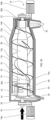
- Fig. 1A is a side view of a decanter centrifuge 10 according to the present invention.
- the decanter centrifuge 10 comprises a rotatable bowl 12 and a conveyor screw 14.
- the bowl 12 has a cylindrical part 12a and a conical part 12b.
- the conveyor screw 14 has a corresponding cylindrical part 14a and conical part 14b.
- the bowl 12 is rotated by a drive motor 16a and the conveyor screw 14 is rotated by a back drive motor 16b.
- the back drive motor 16b is typically connected via a gearbox (not shown).
- An inlet 18 is provided for introducing the feed into the decanter centrifuge 10.
- the bowl 12 comprises a heavy phase outlet 20 at a small end hub 22 at the conical part 12b of the of the bowl 12 and a light phase outlet 24 at a base 26 forming a large end hub at the cylindrical part 12a of the bowl 12.
- the conveyor screw 14 comprises a central body 28 extending in a longitudinal direction between a first bearing surface 30a at the cylindrical part 14a and a second bearing surface 30b at the conical part 14b.
- the conveyor screw 14 comprises a first flight 32 being attached to the central body 28.
- the first flight 32 extends over both the cylindrical part 14a and the conical part 14b of the conveyor screw 14.
- the first flight 32 extending to an inner wall 12c of the bowl 12 and defines a pitch angle being less than 20°.
- the present embodiment further comprises a second flight 34 not extending to the inner wall 12c of the bowl 12 and defining a pitch angle being greater than 30°.
- the second flight 34 does not extend to the inner wall 12c and extends over only the cylindrical part 14a of the conveyor screw 14.
- the base 26 comprising a trunnion 40 which encompasses feed inlets 42 42' for the feed and the bearing surface 30a for the conveyor screw 14.
- the feed inlets 42 42' communicating with the inlet 18.
- the trunnion 40 also comprises at outlet housings 44 extending into the bowl 12 for transporting the light phase from the bowl 12 to the light phase outlet 24.
- Fig. 1B is a side view of a decanter centrifuge 10 according to the present invention showing the inlet and outlet flows.
- the feed is introduced via the inlet 18 as shown by the arrow.
- the feed can be a crushed oil-containing plant- or animal item such as crushed corn seeds.
- the feed enters the bowl 12 via feed inlets 42 42'.
- the feed is separated into a slurry fraction and an oil fraction by centrifugal forces from the rotation of the bowl 12.
- the slurry fraction is a mixture of solids and water.
- the slurry fraction form a heavy phase and are conveyed by the conveyor screw 14 as a slurry which is discharged at the heavy phase outlet 20 as shown by the arrow.
- the oil fraction forms a light phase which is discharged via the outlet housings 44 and light phase outlet 24 as shown by the arrow.
- the slurry fraction being heavier than the oil fraction and will thus flow outwards and accumulate at the inner wall 12c of the bowl 12, the oil fraction being lighter than the slurry fraction and will thus flow inwards and accumulates near the central body.
- the first flight 32 collects the slurry fraction and conveys it towards the heavy phase outlet 20 of the bowl 12, whereas the second flight 34 being able to scrape and spread out the slurry fraction.
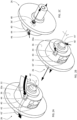
- FIG. 2A is a perspective view of a circular base 26 according to the present invention.
- the base 26 comprises an inner surface 36 facing the interior of the bowl (not shown here) and an outer surface (not visible here) being opposite the inner surface 36 and facing the outside of the bowl.
- the base 26 comprising the trunnion 40 which constitutes a cylindrical element positioned about a centre point C of the base 26 protruding in a longitudinal direction L from the inner surface 36 of the base 26 into the bowl.
- the trunnion 40 comprising a bearing surface 30a for the conveyor screw and feed inlets 42 42' for introducing feed (not shown) into the bowl.
- the bearing surface 30a being located further away in the longitudinal direction L from the inner surface 36 than the feed inlets 42 42' and encircles the centre point C.
- the bearing surface 30a being spaced apart from the centre point C in a radial direction r.
- the radial direction r being perpendicular to the longitudinal direction L.
- the feed inlets 42 42' is located more spaced apart in radial direction r from the centre point C than the bearing surface 40.
- two feed inlets 42 and 42' are provided, whereby the feed inlet 42 is the main feed inlet and the feed inlet 42' is an overflow inlet used during temporary high inflows.
- the trunnion 40 further comprising the outlet housing 44.
- the outlet housing 44 being at least partially cylindrical and extending from the base 26 through the trunnion 40 in the longitudinal direction L into the bowl.
- the outlet housing 44 is located spaced apart in radial direction r from the centre point C, typically further spaced apart from the centre point C than the bearing surface 30a.
- the screw flight 34 ends at the outlet housing 44.
- two outlet housings 44 and 44' are provided spaced apart by 180 degrees about the centre point C.
- the light phase being oil/fat.
- the light phase flows inwardly due to centrifugal forces and enters one of the outlet housings 44 44' as shown by the arrows.
- the light phase enters the outlet housing 44 44' via a light phase opening 46.
- the light phase opening 46 defines a weir edge extending in parallel with the first adjustment axis of the outlet housing 44 44' and defining in normal use a level of the light phase within the bowl.
- the outlet housing 44 44' has a cylindroconical shape having the light phase opening 46' in a conically shaped part of the outlet housing 44 for a smoother flow.
- FIG. 2B is a perspective view of the base showing the discharge of the light phase.
- the light phase enters the outlet housings 44 44' at a radial distance from the centre point C.
- the radial distance of the opening 46 (and thereby the weir) from the centre point C can be adjusted by rotating the outlet housing 44 44' about an adjustment axis A. In this way the level of the light phase within the bowl can be adjusted.
- the bowl rotates causing the feed (not shown) inside the bowl to separate in a heavy phase (not shown) and light liquid phase having a surface at a level, which is slightly above the level of the weir edge thereby providing a pressure head driving the light phase out of the bowl through the opening 46 and the outlet housing 44.
- FIG. 2C is a perspective view of the base from the rear side showing the outer surface 36' and the discharge of the light phase as shown by the arrows.
- the outlet housing 44 extends to the outer surface 36' of the base 26 and defines an outlet 48 at the outer surface 36' of the base 26 for ejecting the light phase.
- the outlet housing 44 can be adjusted about the adjustment axis A from the outside.
- FIG. 3A is a perspective view of the base showing the inflow of the flowable material.
- the flowable material is introduced centrally in the longitudinal direction and flows out in the radial direction into the bowl (not shown) via the feed inlets 42 42'.
- FIG. 3B is a perspective cutaway view of the base 26 showing the interior of the trunnion 40.
- the flowable material is deflected by deflectors 50 from flowing in the longitudinal direction to a direction substantially corresponding to the tangential direction of the rotation of the bowl (not shown). In this way, less time within the bowl is needed to accelerate the flowable material to the bowl rotation speed, and the separation can therefore be more efficient.
- FIG. 3C is a perspective view of the base from the rear side showing the inlet 18.
- the inlet is centrally in the longitudinal direction.
- Fig. 4A is a perspective view of the conveyor screw 14 according to the present invention.
- the conveyor screw 14 comprises the first flight 32 and the second flight 34 being attached to the central body 28.
- the first flight 32 extends over both the cylindrical part 14a and the conical part 14b of the conveyor screw 14 and defines a pitch angle being less than 20° for being able to collect the slurry fraction and convey it towards the heavy phase outlet of the bowl.
- the second flight 34 extends in the longitudinal direction along the cylindrical portion of the conveyor screw 14 only. The first flight 32 and the second flight 34 being at least partially intertwined.
- Both the first flight 32 and the second flight 34 has the same winding direction, however, the second flight 34 defining a pitch angle being more than 30° for scraping and spreading out the slurry at the inner surface of the bowl.
- the second flight 34 extends to a smaller outer perimeter than the first flight 32 for the slurry to be spread out on the inner surface of the bowl. This will allow more oil to be released from the slurry.
- the conveyor screw 14 is further provided with a baffle plate 60 between the cylindrical part 14a and the conical part 14b for preventing oil from flowing towards the heavy phase outlet of the bowl.
- the conveyor screw 14 is further provided with a third flight 52 extending to a smaller outer perimeter than the second flight 34. The purpose of the third flight 52 is to define an oil channel 54 between the second flight 34 and the third flight 52 to allow the oil to flow towards the light phase outlet of the bowl.
- the first flight 32 comprises gaps 56 for allowing the second flight 34 and the third flight 52 to pass through.
- the first flight 32 is slightly offset at the gaps 56 to scrape any slurry which would otherwise be missed due to the gaps 56.
- the conveyor screw 14 further comprises a cage structure 58 extending from the first bearing surface 30a away from the second bearing surface 30b for carrying the first screw 32 beyond the first bearing surface 32a.
- the present conveyor screw 14 also includes an additional fourth flight 34' and fifth flight 52' which essentially correspond to the second flight 34 and third flight 52, respectively, albeit being 180° phase shifted. In this way there will be an additional oil channel 54' and two spread-out effects on the slurry for each turn of the conveyor screw 14.
- the present view also shows the base 26 being attached to the first bearing surface 30a during use.
- the base 28 comprises the feed inlet 42 42' and the outlet housing 44.
- Fig. 4B is a perspective view of the conveyor screw 14 according to the present invention when the base 26 is connected to the first bearing surface 30a.
- the central body 28 being free from any fluid openings between the first bearing surface 30a and the second bearing surface 30b for increasing the structural stability and stiffness of the conveyor screw 14.
Landscapes
- Centrifugal Separators (AREA)
Abstract
The present invention relates to a circular base for a decanter centrifuge. The base accommodated at one longitudinal end of a rotatable bowl of the decanter centrifuge. The base defining an inner surface configured to face an inner space of the bowl, a radial direction extending outwardly from a centre point of the base and a longitudinal direction extending perpendicular to the radial direction. The base defining a first outlet passage extending through the base and a first outlet housing provided at the inner surface and protruding away in the longitudinal direction. The first outlet housing having a first outlet opening for receiving a light phase from the inner space. The first outlet opening comprising a first weir edge defining in normal use a level of a surface of the light phase in the inner space. The first outlet housing is rotatable around a first adjustment axis.
Description
- The present invention relates to a circular base for a decanter centrifuge, a decanter centrifuge and a method of operating a decanter centrifuge.
- Centrifugal based methods, and in particular decanter centrifuges, can be used for separating the oil and fat from the residual solids and liquids when extracting oil and/or fat from oil containing plant- or animal items. In most conventional applications of oil extraction from oil-containing plant- or animal items, such as fish oil extraction, oil from food waste and vegetable oil extraction and in particular corn oil extraction from corn seeds/whole stillage, the solids of the plant- or animal items are removed in a first separation stage, leaving a residue of liquids. The liquids mainly consist of water and oil/fat. The oil/fat is separated from the water in a second separation stage after the solids have been removed.
- By using the above technique, some oil/fat will inevitably be trapped in the compacted solids cake. This oil/fat is considered to be lost as it is not easily recoverable even by resuspension of the solids.
- It has therefore been suggested to remove the oil already in the first separation stage using a two-phase decanter and leaving a residue of solids and liquids. In this way a higher oil yield and a cleaner oil can be obtained.
-
WO 2010/142299 A1 relates to a decanter centrifuge having a conveyor hub with a tubular steel body with an inner core made of a material such as carbon fibre reinforced epoxy. -
WO 2020/109135 A1 relates to a method of producing a low-fat product from a starting material made of a fat and/or oil containing plant- or animal item. The method comprises extracting ta greater part of the extractable oil and/or fat originally contained in the plant- or animal item using a first decanter and leaving a residue of solids and liquids. -
US 7156801 relates to a decanter centrifuge comprising a conveyor screw with one or more flights and having a nominal transport speed varying along the longitudinal axis. The nominal transport speed depends in a non-linear way on the screw pitch. -
DE 102019102623 describes a centrifugal decanter for products that are difficult to de-oil, such as olive pulp, must be mixed particularly intensively so that all or even a residual liquid/residual moisture that is still contained in the solid can be separated more easily. The screw used having two radially offset helices extending over the cylindrical region of the drum and the worm with the same or different winding directions and/or different pitches, so that a radially outer first screw thread and a radially inner second screw thread are formed, so that a part of the suspension to be processed when the drum and screw rotates through the second radially - in relation to the axis of rotation - further inward helix or in conveyed in the radially inner screw flight in a different direction and/or in the same direction and/or at a different speed than at the same time another part of the suspension that is located in the area of the radially further outer helix or the radially outer screw flight. -
US 20150209804 describes an apparatus comprising an outer drum, an inner
drum, an activation spiral and a heavy-material discharging spiral. -
EP 0868217 discloses a decanter centrifuge having several blades arranged to convey axially in the outer drum sludge having settled on the inside of this drum. -
EP 2130607 B1 relates to a decanter centrifuge having the inlet arranged at an end of the casing opposite the end in which the opening for expelling the solid phase is arranged. -
DE 2651657 relates to a centrifugal decanter having a clear fluid discharge between the inlet and the solids outlet. -
US 3268159 relates to a centrifugal decanter in which the feed zone is closer to large end hub than both conveyor bearings. -
JP 62106856 -
US 3494472 relates to a centrifugal separator in the form of a sieve drum. -
US 7022061 describes a centrifugal separator with power recovery discharge pipes for the light phase. -
US 9089852 -
WO 2012/062337 A2 relates to a centrifugal separator comprising an outlet housing being rotatable around an adjustment axis. -
DE 10 2020 129 478 A1 relates to a conveyor screw body having web elements. -
EP 0506835 B1 relates to a decanter centrifuge having at least one bearing of the conveyor supported at the free end of a trunnion. -
EP 0602766 B1 relates to a decanter centrifuge having a central hub having radially projecting support ribs. -
EP 2440335 A1 relates to a decanter centrifuge having conveyor screw comprising a hub with a cylindrical part and a generally conical part, the two parts being interconnected by broad mutually spaced ribs extending in the longitudinal direction. -
EP 2926911 B1 relates to a decanter centrifuge having a centrifuge worm which is mounted at one of its axial end areas by means of a connecting flange. -
EP 3177403 B1 relates to a decanter centrifuge having individual openings in the cylindrical section of the screw hub. -
WO 2021122878A1 relates to a decanter centrifuge having, at least in the inlet area, a screw hub with an open wall structure. -
WO 2021122884A1 relates to a decanter centrifuge having a transverse disk for stabilizing the worm hub construction. -
WO 2022096734A1 relates to a centrifuge screw having rods between at least two winding sections. The rods are formed completely or almost completely spaced. -
WO 2022096739A1 relates to a screw hub for a centrifuge screw having in the longitudinal direction having at least sections of an open wall structure. -
WO 2022096745A1 relates to a centrifuge screw having an open wall structure. The open wall structure extending at most over a length of 50% of the total length of the cylindrical longitudinal section. -
US 8841469 relates to a method of recovering oil from corn by adding a chemical additive. - When separating the oil and fat already in the first separation stage, it is necessary to allow the solids sufficient time to release the oil/fat. It is therefore an object of the present invention to provide technologies for increasing the release of oil from the feed and in particular the oil trapped in the solids of the feed.
- The object of the present invention is in a first aspect achieved by a circular base for a decanter centrifuge, the base being configured to be accommodated at one longitudinal end of a rotatable bowl of the decanter centrifuge, the base defining an inner surface configured to face an inner space of the bowl, a radial direction extending outwardly from a centre point of the base and a longitudinal direction extending perpendicular to the radial direction, the base defining a first outlet passage extending through the base and a first outlet housing provided at the inner surface of the base and protruding away from the inner surface in the longitudinal direction, the first outlet housing having a first outlet opening for receiving a light phase from the inner space, the first outlet housing communicating with the first outlet passage for passing the light phase from the first outlet housing to the first outlet passage, the first outlet opening comprising a first weir edge defining in normal use a level of a surface of the light phase in the inner space, wherein the first outlet housing is rotatable around a first adjustment axis.
- The circular base is used for closing off the decanter centrifuge at the large end hub and provide a bearing surface for the conveyor screw of the decanter centrifuge. The bowl has one or more light phase outlet provided in the circular base at the longitudinal end of the bowl. The heavy phase outlet is located at the opposite longitudinal end of the bowl. The feed in the present case is oil containing plant- or animal items, such as fish oil extraction, oil from food waste and vegetable oil extraction and in particular corn oil extraction from corn seeds/whole stillage. The light phase in the present case is a substantially clean fat/oil in liquid phase separated from the feed, whereas the heavy phase is a residue of the feed being a mixture of other liquids and solids, mainly water and solids.
- By allowing the outlet housing to protrude into the inner space of the bowl, the oil can be discharged at a distance from the base of the bowl. In that way the feed inlet can be located adjacent the base without interfering with the discharge.
- By allowing the outlet housing to be rotatable around the first adjustment axis, the position of the weir edge, and thereby the level of the light phase, can be adjusted by rotating the outlet housing about the adjustment axis. Hereby is obtained that the level of the light phase in the bowl may be adjusted by simply rotating the outlet housing around the adjustment axis, as such rotation will entail an adjustment of the radial distance of the weir edge from the axis of rotation. The weir edge is defined as the point where no information can be transmitted through the discharged medium back into the separation volume inside the decanter. "Information" is anything that can affect the light phase level.
- It should be understood that the centre point means the point on the base corresponding to the axis of rotation of the bowl when is use, the longitudinal direction being parallel to the axis of rotation and the radial direction being perpendicular to the longitudinal direction. The expression "level" refers to a distance in the radial direction from the centre point. In use the bowl rotates causing the feed inside the bowl to separate in a heavy phase and light liquid phase having a surface at a level, which is slightly above the level of the weir edge thereby providing a pressure head driving the light phase out of the bowl through the weir.
- The outlet housing is set in a position relative to the adjustment axis so that the weir edge is positioned further from the axis of rotation than an opposite edge of the outlet opening, and the weir edge can be either the trailing or the leading edge of the outlet opening relative to the rotational movement of the bowl.
- According to a further embodiment of the first aspect, the outlet housing comprises a first side wall offset from the first adjustment axis, the first outlet opening being present in the first side wall. Hereby is obtained that the level of the light phase in the bowl may be adjusted by simply rotating the outlet housing around the adjustment axis, as such rotation will entail an adjustment of the radial distance of the weir edge from the axis of rotation.
- According to a further embodiment of the first aspect, the first outlet housing being at least partially cylindrical having a cylinder axis coaxial with the first adjustment axis. This provides for a simple construction and accordingly cost-efficient production.
- According to a further embodiment of the first aspect, the first weir edge is extending in parallel with the first adjustment axis. In this way the weir edge will be parallel to the light phase surface during use for a well-defined level of the light phase in the bowl.
- According to a further embodiment of the first aspect, the first outlet housing is cylindroconical having the outlet opening in a conical part. By having the outflow in a conical part, the outflow may be smoother and recirculation inside the outlet housing may be avoided.
- According to a further embodiment of the first aspect, the first outlet opening is extending over an angle of 30° to 75°, preferably 45° to 60°, around the first adjustment axis. In this way the outlet opening and especially its angular range of extension around the adjustment axis can be sufficiently large that the outlet opening does not run full during normal operation, but an air-vent can be left between the surface of the out-flowing light phase and the edge opposite the weir edge.
- According to a further embodiment of the first aspect, the first outlet housing has an axial length in the direction of the first adjustment axis, and that the first outlet opening is extending an axial length in the direction of the first adjustment axis shorter than the axial length of the first outlet housing.
- According to a further embodiment of the first aspect, the first adjustment axis is parallel to the longitudinal direction. In this way the position of the weir edge, and thereby the level of the light phase, can be adjusted by rotating the outlet housing about the adjustment axis.
- According to a further embodiment of the first aspect, the base further comprising a bearing surface for a conveyor screw, the bearing surface being located at the inner surface of the base. The base preferably has the additional purpose of accommodating the bearing surface for the conveyor screw.
- According to a further embodiment of the first aspect, the base further comprising a feed inlet for introducing a flowable material into the bowl of the decanter centrifuge, the feed inlet being located at the inwardly oriented surface of the base. The base preferably has the additional purpose of accommodating the feed inlet. The heavy phase of the feed will thereby have a longer travel time through the bowl to reach the heavy phase outlet opposite the base. In this way the solids will have more time to release oil.
- According to a further embodiment of the first aspect, the feed inlet, the bearing surface and the outlet housing are located on a cylindrical part at the inner surface of the base, the cylindrical part protruding in the longitudinal direction. There is a tendency for the conveyor screw to deflect and bend during use, in particular when running at high rotational velocities which are near the eigenfrequency of the conveyor. This problem increases for longer conveyor screw, where the distance between the conveyor bearings is long. By having the bearing surface protruding into the bowl, the distance between the conveyor bearings can be reduced and the eigenfrequency will be higher.
- According to a further embodiment of the first aspect, the first weir edge extends further away from the inner surface than the feed inlet. In this way the feed can be introduced as close as possible to the base without interfering with the light phase outlet.
- According to a further embodiment of the first aspect, the base defining a second outlet passage extending through the base, and a second outlet housing provided at the inner surface, the second outlet housing communicating with the second outlet passage to pass a part of the light phase from the second outlet housing to the second outlet passage, the second outlet housing having a second outlet opening for receiving a part of the light phase from the inner space together with the first outlet opening, the second outlet opening comprising a second weir edge defining in normal use the level of the surface of the light phase in the bowl together with the first weir edge, wherein the second outlet housing is rotatable around a second adjustment axis. To better distribute the outflow from the bowl more than one outlet housing preferably can be used, such as two outlet housings. Even three or more outlet housing can be used to distribute the outflow even better. The weir edges should preferably be set at the same level, i.e. angular position and have the same angular distance in between themselves for them to distribute the outflow optimally between themselves. The outlet housings are preferably identical having the same features as described above.
- The object of the present invention is in a second aspect achieved by decanter centrifuge comprising bowl rotating in use in a direction of rotation around an axis of rotation, the bowl comprising a base according to any of the preceding embodiments of the first aspect at one end of the bowl in the axis of rotation and a heavy phase outlet at an opposite end of the bowl in the axis of rotation, the longitudinal direction of the base coinciding with the axis of rotation. The decanter centrifuge according to the second aspect can preferably be used together with the base according to the first aspect. The heavy phase outlet is located at an opposite end of the bowl relative to the light phase outlet and the feed inlet.
- The object of the present invention is in a third aspect achieved by method of operating a decanter centrifuge according to the second aspect, wherein the method comprising:
- rotating the outlet housing around the first adjustment axis,
- continuously introducing a flowable material into the bowl while rotating the bowl about the axis of rotation, the flowable material including light phase and a heavy phase, and
- allowing the light phase in the bowl to flow out of the bowl via the outlet opening.
- The method according to the third aspect can preferably be used together with the decanter centrifuge according to the second aspect.
-
-
FIG. 1A is a side view of a decanter centrifuge according to the present invention. -
FIG. 1B is a side view of a decanter centrifuge according to the present invention. -
FIG. 2A is a perspective view of a circular base according to the present invention. -
FIG. 2B is a perspective view of the base showing the discharge of the light phase. -
FIG. 2C is a perspective view of the base from the rear side showing the discharge. -
FIG. 3A is a perspective view of the base showing the inflow of the flowable material. -
FIG. 3B is a perspective cutaway view of the base showing the trunnion interior. -
FIG. 3C is a perspective view of the base from the rear side showing the inflow. -
FIG. 4A is a perspective view of the conveyor screw. -
FIG. 4B is a perspective view of the conveyor screw. -
Fig. 1A is a side view of adecanter centrifuge 10 according to the present invention. Thedecanter centrifuge 10 comprises arotatable bowl 12 and aconveyor screw 14. Thebowl 12 has acylindrical part 12a and aconical part 12b. Theconveyor screw 14 has a correspondingcylindrical part 14a andconical part 14b. Thebowl 12 is rotated by adrive motor 16a and theconveyor screw 14 is rotated by aback drive motor 16b. Theback drive motor 16b is typically connected via a gearbox (not shown). Aninlet 18 is provided for introducing the feed into thedecanter centrifuge 10. Thebowl 12 comprises aheavy phase outlet 20 at asmall end hub 22 at theconical part 12b of the of thebowl 12 and alight phase outlet 24 at a base 26 forming a large end hub at thecylindrical part 12a of thebowl 12. - The
conveyor screw 14 comprises acentral body 28 extending in a longitudinal direction between afirst bearing surface 30a at thecylindrical part 14a and asecond bearing surface 30b at theconical part 14b. Theconveyor screw 14 comprises afirst flight 32 being attached to thecentral body 28. Thefirst flight 32 extends over both thecylindrical part 14a and theconical part 14b of theconveyor screw 14. Thefirst flight 32 extending to aninner wall 12c of thebowl 12 and defines a pitch angle being less than 20°. The present embodiment further comprises asecond flight 34 not extending to theinner wall 12c of thebowl 12 and defining a pitch angle being greater than 30°. The pitch angle is here calculated by the expression: Pitch angle = ATAN(Pitch/(π*(Bowl diameter))). Thesecond flight 34 does not extend to theinner wall 12c and extends over only thecylindrical part 14a of theconveyor screw 14. The base 26 comprising atrunnion 40 which encompassesfeed inlets 42 42' for the feed and thebearing surface 30a for theconveyor screw 14. The feed inlets 42 42' communicating with theinlet 18. Thetrunnion 40 also comprises atoutlet housings 44 extending into thebowl 12 for transporting the light phase from thebowl 12 to thelight phase outlet 24. -
Fig. 1B is a side view of adecanter centrifuge 10 according to the present invention showing the inlet and outlet flows. The feed is introduced via theinlet 18 as shown by the arrow. The feed can be a crushed oil-containing plant- or animal item such as crushed corn seeds. The feed enters thebowl 12 viafeed inlets 42 42'. The feed is separated into a slurry fraction and an oil fraction by centrifugal forces from the rotation of thebowl 12. The slurry fraction is a mixture of solids and water. The slurry fraction form a heavy phase and are conveyed by theconveyor screw 14 as a slurry which is discharged at theheavy phase outlet 20 as shown by the arrow. The oil fraction forms a light phase which is discharged via the outlet housings 44 andlight phase outlet 24 as shown by the arrow. The slurry fraction being heavier than the oil fraction and will thus flow outwards and accumulate at theinner wall 12c of thebowl 12, the oil fraction being lighter than the slurry fraction and will thus flow inwards and accumulates near the central body. Thefirst flight 32 collects the slurry fraction and conveys it towards theheavy phase outlet 20 of thebowl 12, whereas thesecond flight 34 being able to scrape and spread out the slurry fraction. -
FIG. 2A is a perspective view of acircular base 26 according to the present invention. Thebase 26 comprises aninner surface 36 facing the interior of the bowl (not shown here) and an outer surface (not visible here) being opposite theinner surface 36 and facing the outside of the bowl. The base 26 comprising thetrunnion 40 which constitutes a cylindrical element positioned about a centre point C of the base 26 protruding in a longitudinal direction L from theinner surface 36 of the base 26 into the bowl. - The
trunnion 40 comprising abearing surface 30a for the conveyor screw and feedinlets 42 42' for introducing feed (not shown) into the bowl. The bearingsurface 30a being located further away in the longitudinal direction L from theinner surface 36 than thefeed inlets 42 42' and encircles the centre point C. The bearingsurface 30a being spaced apart from the centre point C in a radial direction r. The radial direction r being perpendicular to the longitudinal direction L. The feed inlets 42 42' is located more spaced apart in radial direction r from the centre point C than the bearingsurface 40. In the present embodiment, twofeed inlets 42 and 42' are provided, whereby thefeed inlet 42 is the main feed inlet and the feed inlet 42' is an overflow inlet used during temporary high inflows. - The
trunnion 40 further comprising theoutlet housing 44. Theoutlet housing 44 being at least partially cylindrical and extending from the base 26 through thetrunnion 40 in the longitudinal direction L into the bowl. Theoutlet housing 44 is located spaced apart in radial direction r from the centre point C, typically further spaced apart from the centre point C than the bearingsurface 30a. In the present embodiment, thescrew flight 34 ends at theoutlet housing 44. Further, in the present embodiment twooutlet housings 44 and 44' are provided spaced apart by 180 degrees about the centre point C. - The light phase being oil/fat. During use, the light phase flows inwardly due to centrifugal forces and enters one of the outlet housings 44 44' as shown by the arrows. The light phase enters the
outlet housing 44 44' via alight phase opening 46. (Only the light phase opening 46' of the outlet housing 44' is visible in the present view, however, theoutlet housing 44 has an identically configured light phase opening). The light phase opening 46 defines a weir edge extending in parallel with the first adjustment axis of theoutlet housing 44 44' and defining in normal use a level of the light phase within the bowl. In the present embodiment, theoutlet housing 44 44' has a cylindroconical shape having the light phase opening 46' in a conically shaped part of theoutlet housing 44 for a smoother flow. -
FIG. 2B is a perspective view of the base showing the discharge of the light phase. The light phase enters the outlet housings 44 44' at a radial distance from the centre point C. The radial distance of the opening 46 (and thereby the weir) from the centre point C can be adjusted by rotating theoutlet housing 44 44' about an adjustment axis A. In this way the level of the light phase within the bowl can be adjusted. In use the bowl (not shown) rotates causing the feed (not shown) inside the bowl to separate in a heavy phase (not shown) and light liquid phase having a surface at a level, which is slightly above the level of the weir edge thereby providing a pressure head driving the light phase out of the bowl through theopening 46 and theoutlet housing 44. -
FIG. 2C is a perspective view of the base from the rear side showing the outer surface 36' and the discharge of the light phase as shown by the arrows. Theoutlet housing 44 extends to the outer surface 36' of thebase 26 and defines anoutlet 48 at the outer surface 36' of thebase 26 for ejecting the light phase. Theoutlet housing 44 can be adjusted about the adjustment axis A from the outside. -
FIG. 3A is a perspective view of the base showing the inflow of the flowable material. The flowable material is introduced centrally in the longitudinal direction and flows out in the radial direction into the bowl (not shown) via thefeed inlets 42 42'. -
FIG. 3B is a perspective cutaway view of the base 26 showing the interior of thetrunnion 40. As can be seen the flowable material is deflected bydeflectors 50 from flowing in the longitudinal direction to a direction substantially corresponding to the tangential direction of the rotation of the bowl (not shown). In this way, less time within the bowl is needed to accelerate the flowable material to the bowl rotation speed, and the separation can therefore be more efficient. -
FIG. 3C is a perspective view of the base from the rear side showing theinlet 18. The inlet is centrally in the longitudinal direction. -
Fig. 4A is a perspective view of theconveyor screw 14 according to the present invention. Theconveyor screw 14 comprises thefirst flight 32 and thesecond flight 34 being attached to thecentral body 28. Thefirst flight 32 extends over both thecylindrical part 14a and theconical part 14b of theconveyor screw 14 and defines a pitch angle being less than 20° for being able to collect the slurry fraction and convey it towards the heavy phase outlet of the bowl. Thesecond flight 34 extends in the longitudinal direction along the cylindrical portion of theconveyor screw 14 only. Thefirst flight 32 and thesecond flight 34 being at least partially intertwined. - Both the
first flight 32 and thesecond flight 34 has the same winding direction, however, thesecond flight 34 defining a pitch angle being more than 30° for scraping and spreading out the slurry at the inner surface of the bowl. Thesecond flight 34 extends to a smaller outer perimeter than thefirst flight 32 for the slurry to be spread out on the inner surface of the bowl. This will allow more oil to be released from the slurry. - The
conveyor screw 14 is further provided with abaffle plate 60 between thecylindrical part 14a and theconical part 14b for preventing oil from flowing towards the heavy phase outlet of the bowl. Theconveyor screw 14 is further provided with athird flight 52 extending to a smaller outer perimeter than thesecond flight 34. The purpose of thethird flight 52 is to define anoil channel 54 between thesecond flight 34 and thethird flight 52 to allow the oil to flow towards the light phase outlet of the bowl. - The
first flight 32 comprisesgaps 56 for allowing thesecond flight 34 and thethird flight 52 to pass through. Thefirst flight 32 is slightly offset at thegaps 56 to scrape any slurry which would otherwise be missed due to thegaps 56. Theconveyor screw 14 further comprises acage structure 58 extending from thefirst bearing surface 30a away from thesecond bearing surface 30b for carrying thefirst screw 32 beyond the first bearing surface 32a. - The
present conveyor screw 14 also includes an additional fourth flight 34' and fifth flight 52' which essentially correspond to thesecond flight 34 andthird flight 52, respectively, albeit being 180° phase shifted. In this way there will be an additional oil channel 54' and two spread-out effects on the slurry for each turn of theconveyor screw 14. - The present view also shows the base 26 being attached to the
first bearing surface 30a during use. Thebase 28 comprises thefeed inlet 42 42' and theoutlet housing 44. -
Fig. 4B is a perspective view of theconveyor screw 14 according to the present invention when thebase 26 is connected to thefirst bearing surface 30a. Thecentral body 28 being free from any fluid openings between thefirst bearing surface 30a and thesecond bearing surface 30b for increasing the structural stability and stiffness of theconveyor screw 14.
Claims (15)
- A circular base for a decanter centrifuge, the base being configured to be accommodated at one longitudinal end of a rotatable bowl of the decanter centrifuge, the base defining an inner surface configured to face an inner space of the bowl, a radial direction extending outwardly from a centre point of the base and a longitudinal direction extending perpendicular to the radial direction, the base defining a first outlet passage extending through the base and a first outlet housing provided at the inner surface of the base and protruding away from the inner surface in the longitudinal direction, the first outlet housing having a first outlet opening for receiving a light phase from the inner space, the first outlet housing communicating with the first outlet passage for passing the light phase from the first outlet housing to the first outlet passage, the first outlet opening comprising a first weir edge defining in normal use a level of a surface of the light phase in the inner space, wherein the first outlet housing is rotatable around a first adjustment axis.
- The circular base according to claim 1, wherein the outlet housing comprises a first side wall offset from the first adjustment axis, the first outlet opening being present in the first side wall.
- The circular base according to any of the preceding claims, wherein the first outlet housing being at least partially cylindrical having a cylinder axis coaxial with the first adjustment axis.
- The circular base according to claim 3, wherein the first weir edge is extending in parallel with the first adjustment axis.
- The circular base according to any of the preceding claims, wherein the first outlet housing is cylindroconical having the outlet opening in a conical part.
- The circular base according to any of the preceding claims, wherein the first outlet opening is extending over an angle of 30° to 90°, preferably 45° to 75°, around the first adjustment axis.
- The circular base according to any of the preceding claims, wherein the first outlet housing has an axial length in the direction of the first adjustment axis, and that the first outlet opening is extending an axial length in the direction of the first adjustment axis shorter than the axial length of the first outlet housing.
- The circular base according to any of the preceding claims, wherein the first adjustment axis is parallel to the longitudinal direction.
- The circular base according to any of the preceding claims, wherein the base further comprising a bearing surface for a conveyor screw, the bearing surface being located at the inner surface of the base.
- The circular base according to any of the preceding claims, wherein the base further comprising a feed inlet for introducing a flowable material into the bowl of the decanter centrifuge, the feed inlet being located at the inwardly oriented surface of the base.
- The circular base according to claim 9 and 10, wherein the feed inlet, the bearing surface and the outlet housing are located on a cylindrical part at the inner surface of the base, the cylindrical part protruding in the longitudinal direction.
- The circular base according to any of the claims 10-11, wherein the first weir edge extends further away from the inner surface than the feed inlet.
- The circular base according to any of the preceding claims, wherein the base defining a second outlet passage extending through the base, and a second outlet housing provided at the inner surface, the second outlet housing communicating with the second outlet passage to pass a part of the light phase from the second outlet housing to the second outlet passage, the second outlet housing having a second outlet opening for receiving a part of the light phase from the inner space together with the first outlet opening, the second outlet opening comprising a second weir edge defining in normal use the level of the surface of the light phase in the bowl together with the first weir edge, wherein the second outlet housing is rotatable around a second adjustment axis.
- A decanter centrifuge comprising bowl rotating in use in a direction of rotation around an axis of rotation, the bowl comprising a base according to any of the preceding claims at one end of the bowl in the axis of rotation and a heavy phase outlet at an opposite end of the bowl in the axis of rotation, the longitudinal direction of the base coinciding with the axis of rotation.
- A method of operating a decanter centrifuge according to claim 14, wherein the method comprising:rotating the outlet housing around the first adjustment axis,continuously introducing a flowable material into the bowl while rotating the bowl about the axis of rotation, the flowable material including light phase and a heavy phase, andallowing the light phase in the bowl to flow out of the bowl via the outlet opening.
Priority Applications (2)
| Application Number | Priority Date | Filing Date | Title |
|---|---|---|---|
| EP23213451.0A EP4563231A1 (en) | 2023-11-30 | 2023-11-30 | A decanter centrifuge for separating feed material |
| PCT/EP2024/084012 WO2025114493A1 (en) | 2023-11-30 | 2024-11-28 | A decanter centrifuge for separating feed material |
Applications Claiming Priority (1)
| Application Number | Priority Date | Filing Date | Title |
|---|---|---|---|
| EP23213451.0A EP4563231A1 (en) | 2023-11-30 | 2023-11-30 | A decanter centrifuge for separating feed material |
Publications (1)
| Publication Number | Publication Date |
|---|---|
| EP4563231A1 true EP4563231A1 (en) | 2025-06-04 |
Family
ID=89029536
Family Applications (1)
| Application Number | Title | Priority Date | Filing Date |
|---|---|---|---|
| EP23213451.0A Withdrawn EP4563231A1 (en) | 2023-11-30 | 2023-11-30 | A decanter centrifuge for separating feed material |
Country Status (1)
| Country | Link |
|---|---|
| EP (1) | EP4563231A1 (en) |
Citations (29)
| Publication number | Priority date | Publication date | Assignee | Title |
|---|---|---|---|---|
| US3268159A (en) | 1962-10-16 | 1966-08-23 | Voith Gmbh J M | Centrifuge |
| US3494472A (en) | 1967-06-16 | 1970-02-10 | Heinkel Maschinenbau Kg Ernst | Sieve centrifuge |
| DE2651657A1 (en) | 1976-11-12 | 1978-05-24 | Robert Kern | Screw centrifuge for extracting solids from suspensions - operates with continuous smooth flow through separation stage to outlets |
| JPS62106856A (en) | 1985-11-05 | 1987-05-18 | Kubota Ltd | Horizontal centrifugal concentrator |
| EP0506835B1 (en) | 1989-12-29 | 1994-07-13 | Alfa-Laval Separation A/S | Decanter centrifuge |
| EP0868217A1 (en) | 1995-12-21 | 1998-10-07 | Alfa Laval Separation Ab | Decanter centrifuge |
| EP0602766B1 (en) | 1992-12-17 | 2000-06-07 | Alfa Laval Separation Inc. | Decanter centrifuge for thickening at high rates |
| JP2001314779A (en) * | 2000-05-11 | 2001-11-13 | Tomoe Engineering Co Ltd | Decanter-type centrifugal separator, method of operating the same and system equipped with the same |
| US7022061B2 (en) | 2002-10-15 | 2006-04-04 | Andritz Ag | Centrifuge discharge port with power recovery |
| US7156801B2 (en) | 2002-04-22 | 2007-01-02 | Alfa Laval Copenhagen A/S | Decanter centrifuge with a screw conveyor having a varying pitch |
| WO2010142299A1 (en) | 2009-06-12 | 2010-12-16 | Alfa Laval Corporate Ab | A decanter centrifuge and a screw conveyor |
| EP2130607B1 (en) | 2008-06-06 | 2012-04-11 | Mantovani & Vicentini S.r.L. | Centrifugal separator |
| EP2440335A1 (en) | 2009-06-12 | 2012-04-18 | Alfa Laval Corporate AB | A centrifugal separator |
| WO2012062337A2 (en) | 2010-11-12 | 2012-05-18 | Alfa Laval Corporate Ab | A centrifugal separator and an outlet element for a centrifugal separator |
| US8841469B2 (en) | 2011-03-21 | 2014-09-23 | Solenis Technologies, L.P. | Chemical additives and use thereof in stillage processing operations |
| US9089852B2 (en) | 2011-12-22 | 2015-07-28 | Gea Mechanical Equipment Gmbh | Fully jacketed screw centrifuge with a hose segment arranged in the solids capture chamber |
| US20150209804A1 (en) | 2012-08-15 | 2015-07-30 | Qinzhou Aurasource Technology Inc. | Centrifugal separation device |
| EP2926911B1 (en) | 2014-04-04 | 2016-07-06 | Flottweg SE | Solid bowl worm centrifuge with a connection flange |
| EP3177403B1 (en) | 2014-08-05 | 2018-05-02 | Flottweg SE | Screw of a solid bowl centrifuge |
| KR102000530B1 (en) * | 2018-02-20 | 2019-07-16 | (주)부성원심분리기 | Centrifuge for waste water treatment |
| CN110721824A (en) * | 2019-11-18 | 2020-01-24 | 江苏同泽过滤科技有限公司 | Overflow depth adjusting device in horizontal spiral sedimentation centrifuge |
| WO2020109135A1 (en) | 2018-11-30 | 2020-06-04 | Alfa Laval Corporate Ab | Method of producing a low-fat product and a system for producing a low-fat product |
| DE102019102623A1 (en) | 2019-02-04 | 2020-08-06 | Gea Mechanical Equipment Gmbh | Process for clarifying a suspension of solids |
| WO2021122878A1 (en) | 2019-12-19 | 2021-06-24 | Flottweg Se | Inlet region of a centrifuge screw, and solid bowl centrifuge |
| WO2021122884A1 (en) | 2019-12-19 | 2021-06-24 | Flottweg Se | Transverse disc of a centrifuge screw, and solid-bowl screw centrifuge |
| WO2022096745A1 (en) | 2020-11-09 | 2022-05-12 | Flottweg Se | Centrifugal screw, and solid bowl screw centrifuge |
| WO2022096739A1 (en) | 2020-11-09 | 2022-05-12 | Flottweg Se | Screw hub, centrifugal screw, and solid bowl screw centrifuge |
| WO2022096734A1 (en) | 2020-11-09 | 2022-05-12 | Flottweg Se | Centrifugal screw, and solid bowl screw centrifuge |
| DE102020129478A1 (en) | 2020-11-09 | 2022-06-02 | Flottweg Se | Worm hub, centrifuge worm and solid bowl worm centrifuge |
-
2023
- 2023-11-30 EP EP23213451.0A patent/EP4563231A1/en not_active Withdrawn
Patent Citations (30)
| Publication number | Priority date | Publication date | Assignee | Title |
|---|---|---|---|---|
| US3268159A (en) | 1962-10-16 | 1966-08-23 | Voith Gmbh J M | Centrifuge |
| US3494472A (en) | 1967-06-16 | 1970-02-10 | Heinkel Maschinenbau Kg Ernst | Sieve centrifuge |
| DE2651657A1 (en) | 1976-11-12 | 1978-05-24 | Robert Kern | Screw centrifuge for extracting solids from suspensions - operates with continuous smooth flow through separation stage to outlets |
| JPS62106856A (en) | 1985-11-05 | 1987-05-18 | Kubota Ltd | Horizontal centrifugal concentrator |
| EP0506835B1 (en) | 1989-12-29 | 1994-07-13 | Alfa-Laval Separation A/S | Decanter centrifuge |
| EP0602766B1 (en) | 1992-12-17 | 2000-06-07 | Alfa Laval Separation Inc. | Decanter centrifuge for thickening at high rates |
| EP0868217A1 (en) | 1995-12-21 | 1998-10-07 | Alfa Laval Separation Ab | Decanter centrifuge |
| JP2001314779A (en) * | 2000-05-11 | 2001-11-13 | Tomoe Engineering Co Ltd | Decanter-type centrifugal separator, method of operating the same and system equipped with the same |
| US7156801B2 (en) | 2002-04-22 | 2007-01-02 | Alfa Laval Copenhagen A/S | Decanter centrifuge with a screw conveyor having a varying pitch |
| US7022061B2 (en) | 2002-10-15 | 2006-04-04 | Andritz Ag | Centrifuge discharge port with power recovery |
| EP2130607B1 (en) | 2008-06-06 | 2012-04-11 | Mantovani & Vicentini S.r.L. | Centrifugal separator |
| WO2010142299A1 (en) | 2009-06-12 | 2010-12-16 | Alfa Laval Corporate Ab | A decanter centrifuge and a screw conveyor |
| EP2440335A1 (en) | 2009-06-12 | 2012-04-18 | Alfa Laval Corporate AB | A centrifugal separator |
| EP2637795B1 (en) * | 2010-11-12 | 2017-01-18 | Alfa Laval Corporate AB | A centrifugal separator and an outlet element for a centrifugal separator |
| WO2012062337A2 (en) | 2010-11-12 | 2012-05-18 | Alfa Laval Corporate Ab | A centrifugal separator and an outlet element for a centrifugal separator |
| US8841469B2 (en) | 2011-03-21 | 2014-09-23 | Solenis Technologies, L.P. | Chemical additives and use thereof in stillage processing operations |
| US9089852B2 (en) | 2011-12-22 | 2015-07-28 | Gea Mechanical Equipment Gmbh | Fully jacketed screw centrifuge with a hose segment arranged in the solids capture chamber |
| US20150209804A1 (en) | 2012-08-15 | 2015-07-30 | Qinzhou Aurasource Technology Inc. | Centrifugal separation device |
| EP2926911B1 (en) | 2014-04-04 | 2016-07-06 | Flottweg SE | Solid bowl worm centrifuge with a connection flange |
| EP3177403B1 (en) | 2014-08-05 | 2018-05-02 | Flottweg SE | Screw of a solid bowl centrifuge |
| KR102000530B1 (en) * | 2018-02-20 | 2019-07-16 | (주)부성원심분리기 | Centrifuge for waste water treatment |
| WO2020109135A1 (en) | 2018-11-30 | 2020-06-04 | Alfa Laval Corporate Ab | Method of producing a low-fat product and a system for producing a low-fat product |
| DE102019102623A1 (en) | 2019-02-04 | 2020-08-06 | Gea Mechanical Equipment Gmbh | Process for clarifying a suspension of solids |
| CN110721824A (en) * | 2019-11-18 | 2020-01-24 | 江苏同泽过滤科技有限公司 | Overflow depth adjusting device in horizontal spiral sedimentation centrifuge |
| WO2021122878A1 (en) | 2019-12-19 | 2021-06-24 | Flottweg Se | Inlet region of a centrifuge screw, and solid bowl centrifuge |
| WO2021122884A1 (en) | 2019-12-19 | 2021-06-24 | Flottweg Se | Transverse disc of a centrifuge screw, and solid-bowl screw centrifuge |
| WO2022096745A1 (en) | 2020-11-09 | 2022-05-12 | Flottweg Se | Centrifugal screw, and solid bowl screw centrifuge |
| WO2022096739A1 (en) | 2020-11-09 | 2022-05-12 | Flottweg Se | Screw hub, centrifugal screw, and solid bowl screw centrifuge |
| WO2022096734A1 (en) | 2020-11-09 | 2022-05-12 | Flottweg Se | Centrifugal screw, and solid bowl screw centrifuge |
| DE102020129478A1 (en) | 2020-11-09 | 2022-06-02 | Flottweg Se | Worm hub, centrifuge worm and solid bowl worm centrifuge |
Similar Documents
| Publication | Publication Date | Title |
|---|---|---|
| RU2223151C2 (en) | Centrifugal with additional section of rotor | |
| CN1305578C (en) | Spiral centrifuge | |
| EP2252405A1 (en) | A separation device | |
| US20110097249A1 (en) | Centrifuge cartridge | |
| AU2002221724B2 (en) | Solid-bowl screw centrifuge | |
| CN1388766A (en) | Automatic Solids Discharge Tubular Bowl Centrifugal Separator | |
| CN116583354A (en) | Screw hub, centrifugal screw and non-porous bowl screw centrifuges | |
| US8523749B2 (en) | Three-phase solid bowl screw centrifuge and method of controlling the separating process | |
| CN103443577B (en) | Centrifugal Liquid Separator for Efficient Flow of Multiphase Solids in a Heavy Phase Discharge Stream | |
| EP2475461B1 (en) | Centrifugal separator, method for separating | |
| RU2482922C2 (en) | Centrifuge with screen bowl | |
| WO1992005876A1 (en) | Method and apparatus for reduction of particles disintegration | |
| EP4563234A1 (en) | A decanter centrifuge for separating feed material | |
| EP4563233A1 (en) | A decanter centrifuge for separating feed material | |
| EP4563232A1 (en) | A decanter centrifuge for separating feed material | |
| WO2025114493A1 (en) | A decanter centrifuge for separating feed material | |
| GB2083381A (en) | Uniflow decanter centrifuge | |
| CN121311312A (en) | Non-perforated rotary screw centrifuge | |
| KR100494228B1 (en) | Centrifugal separator | |
| JP3748798B2 (en) | centrifuge | |
| CN212856215U (en) | Overflow type three-phase separator | |
| WO2003101619A1 (en) | Centrifugal separator bowl assembly with flow guide | |
| JPH0459065A (en) | Screw centrifugal separator | |
| AU2023235501B2 (en) | Decanter centrifuge with lamellae for improved fines recovery | |
| JP2006272058A (en) | Centrifuge |
Legal Events
| Date | Code | Title | Description |
|---|---|---|---|
| PUAI | Public reference made under article 153(3) epc to a published international application that has entered the european phase |
Free format text: ORIGINAL CODE: 0009012 |
|
| STAA | Information on the status of an ep patent application or granted ep patent |
Free format text: STATUS: THE APPLICATION HAS BEEN PUBLISHED |
|
| AK | Designated contracting states |
Kind code of ref document: A1 Designated state(s): AL AT BE BG CH CY CZ DE DK EE ES FI FR GB GR HR HU IE IS IT LI LT LU LV MC ME MK MT NL NO PL PT RO RS SE SI SK SM TR |
|
| STAA | Information on the status of an ep patent application or granted ep patent |
Free format text: STATUS: THE APPLICATION IS DEEMED TO BE WITHDRAWN |
|
| 18D | Application deemed to be withdrawn |
Effective date: 20251205 |