EP4563224A1 - Filter and method for manufacturing same - Google Patents
Filter and method for manufacturing same Download PDFInfo
- Publication number
- EP4563224A1 EP4563224A1 EP23850110.0A EP23850110A EP4563224A1 EP 4563224 A1 EP4563224 A1 EP 4563224A1 EP 23850110 A EP23850110 A EP 23850110A EP 4563224 A1 EP4563224 A1 EP 4563224A1
- Authority
- EP
- European Patent Office
- Prior art keywords
- base material
- biotin
- compound
- filter
- valve
- Prior art date
- Legal status (The legal status is an assumption and is not a legal conclusion. Google has not performed a legal analysis and makes no representation as to the accuracy of the status listed.)
- Pending
Links
Images








Classifications
-
- B—PERFORMING OPERATIONS; TRANSPORTING
- B01—PHYSICAL OR CHEMICAL PROCESSES OR APPARATUS IN GENERAL
- B01D—SEPARATION
- B01D15/00—Separating processes involving the treatment of liquids with solid sorbents; Apparatus therefor
- B01D15/08—Selective adsorption, e.g. chromatography
- B01D15/26—Selective adsorption, e.g. chromatography characterised by the separation mechanism
- B01D15/38—Selective adsorption, e.g. chromatography characterised by the separation mechanism involving specific interaction not covered by one or more of groups B01D15/265 and B01D15/30 - B01D15/36, e.g. affinity, ligand exchange or chiral chromatography
- B01D15/3804—Affinity chromatography
- B01D15/3823—Affinity chromatography of other types, e.g. avidin, streptavidin or biotin
-
- B—PERFORMING OPERATIONS; TRANSPORTING
- B01—PHYSICAL OR CHEMICAL PROCESSES OR APPARATUS IN GENERAL
- B01D—SEPARATION
- B01D67/00—Processes specially adapted for manufacturing semi-permeable membranes for separation processes or apparatus
- B01D67/0081—After-treatment of organic or inorganic membranes
- B01D67/009—After-treatment of organic or inorganic membranes with wave-energy, particle-radiation or plasma
-
- B—PERFORMING OPERATIONS; TRANSPORTING
- B01—PHYSICAL OR CHEMICAL PROCESSES OR APPARATUS IN GENERAL
- B01D—SEPARATION
- B01D71/00—Semi-permeable membranes for separation processes or apparatus characterised by the material; Manufacturing processes specially adapted therefor
- B01D71/06—Organic material
- B01D71/54—Polyureas; Polyurethanes
-
- B—PERFORMING OPERATIONS; TRANSPORTING
- B01—PHYSICAL OR CHEMICAL PROCESSES OR APPARATUS IN GENERAL
- B01J—CHEMICAL OR PHYSICAL PROCESSES, e.g. CATALYSIS OR COLLOID CHEMISTRY; THEIR RELEVANT APPARATUS
- B01J20/00—Solid sorbent compositions or filter aid compositions; Sorbents for chromatography; Processes for preparing, regenerating or reactivating thereof
- B01J20/22—Solid sorbent compositions or filter aid compositions; Sorbents for chromatography; Processes for preparing, regenerating or reactivating thereof comprising organic material
- B01J20/26—Synthetic macromolecular compounds
-
- B—PERFORMING OPERATIONS; TRANSPORTING
- B01—PHYSICAL OR CHEMICAL PROCESSES OR APPARATUS IN GENERAL
- B01J—CHEMICAL OR PHYSICAL PROCESSES, e.g. CATALYSIS OR COLLOID CHEMISTRY; THEIR RELEVANT APPARATUS
- B01J20/00—Solid sorbent compositions or filter aid compositions; Sorbents for chromatography; Processes for preparing, regenerating or reactivating thereof
- B01J20/22—Solid sorbent compositions or filter aid compositions; Sorbents for chromatography; Processes for preparing, regenerating or reactivating thereof comprising organic material
- B01J20/26—Synthetic macromolecular compounds
- B01J20/264—Synthetic macromolecular compounds derived from different types of monomers, e.g. linear or branched copolymers, block copolymers, graft copolymers
-
- B—PERFORMING OPERATIONS; TRANSPORTING
- B01—PHYSICAL OR CHEMICAL PROCESSES OR APPARATUS IN GENERAL
- B01J—CHEMICAL OR PHYSICAL PROCESSES, e.g. CATALYSIS OR COLLOID CHEMISTRY; THEIR RELEVANT APPARATUS
- B01J20/00—Solid sorbent compositions or filter aid compositions; Sorbents for chromatography; Processes for preparing, regenerating or reactivating thereof
- B01J20/28—Solid sorbent compositions or filter aid compositions; Sorbents for chromatography; Processes for preparing, regenerating or reactivating thereof characterised by their form or physical properties
- B01J20/28014—Solid sorbent compositions or filter aid compositions; Sorbents for chromatography; Processes for preparing, regenerating or reactivating thereof characterised by their form or physical properties characterised by their form
- B01J20/28052—Several layers of identical or different sorbents stacked in a housing, e.g. in a column
-
- B—PERFORMING OPERATIONS; TRANSPORTING
- B01—PHYSICAL OR CHEMICAL PROCESSES OR APPARATUS IN GENERAL
- B01J—CHEMICAL OR PHYSICAL PROCESSES, e.g. CATALYSIS OR COLLOID CHEMISTRY; THEIR RELEVANT APPARATUS
- B01J20/00—Solid sorbent compositions or filter aid compositions; Sorbents for chromatography; Processes for preparing, regenerating or reactivating thereof
- B01J20/28—Solid sorbent compositions or filter aid compositions; Sorbents for chromatography; Processes for preparing, regenerating or reactivating thereof characterised by their form or physical properties
- B01J20/28054—Solid sorbent compositions or filter aid compositions; Sorbents for chromatography; Processes for preparing, regenerating or reactivating thereof characterised by their form or physical properties characterised by their surface properties or porosity
- B01J20/28078—Pore diameter
- B01J20/2808—Pore diameter being less than 2 nm, i.e. micropores or nanopores
-
- B—PERFORMING OPERATIONS; TRANSPORTING
- B01—PHYSICAL OR CHEMICAL PROCESSES OR APPARATUS IN GENERAL
- B01J—CHEMICAL OR PHYSICAL PROCESSES, e.g. CATALYSIS OR COLLOID CHEMISTRY; THEIR RELEVANT APPARATUS
- B01J20/00—Solid sorbent compositions or filter aid compositions; Sorbents for chromatography; Processes for preparing, regenerating or reactivating thereof
- B01J20/30—Processes for preparing, regenerating, or reactivating
- B01J20/32—Impregnating or coating ; Solid sorbent compositions obtained from processes involving impregnating or coating
- B01J20/3202—Impregnating or coating ; Solid sorbent compositions obtained from processes involving impregnating or coating characterised by the carrier, support or substrate used for impregnation or coating
- B01J20/3206—Organic carriers, supports or substrates
- B01J20/3208—Polymeric carriers, supports or substrates
- B01J20/321—Polymeric carriers, supports or substrates consisting of a polymer obtained by reactions involving only carbon to carbon unsaturated bonds
-
- B—PERFORMING OPERATIONS; TRANSPORTING
- B01—PHYSICAL OR CHEMICAL PROCESSES OR APPARATUS IN GENERAL
- B01J—CHEMICAL OR PHYSICAL PROCESSES, e.g. CATALYSIS OR COLLOID CHEMISTRY; THEIR RELEVANT APPARATUS
- B01J20/00—Solid sorbent compositions or filter aid compositions; Sorbents for chromatography; Processes for preparing, regenerating or reactivating thereof
- B01J20/30—Processes for preparing, regenerating, or reactivating
- B01J20/32—Impregnating or coating ; Solid sorbent compositions obtained from processes involving impregnating or coating
- B01J20/3202—Impregnating or coating ; Solid sorbent compositions obtained from processes involving impregnating or coating characterised by the carrier, support or substrate used for impregnation or coating
- B01J20/3206—Organic carriers, supports or substrates
- B01J20/3208—Polymeric carriers, supports or substrates
- B01J20/3212—Polymeric carriers, supports or substrates consisting of a polymer obtained by reactions otherwise than involving only carbon to carbon unsaturated bonds
-
- B—PERFORMING OPERATIONS; TRANSPORTING
- B01—PHYSICAL OR CHEMICAL PROCESSES OR APPARATUS IN GENERAL
- B01J—CHEMICAL OR PHYSICAL PROCESSES, e.g. CATALYSIS OR COLLOID CHEMISTRY; THEIR RELEVANT APPARATUS
- B01J20/00—Solid sorbent compositions or filter aid compositions; Sorbents for chromatography; Processes for preparing, regenerating or reactivating thereof
- B01J20/30—Processes for preparing, regenerating, or reactivating
- B01J20/32—Impregnating or coating ; Solid sorbent compositions obtained from processes involving impregnating or coating
- B01J20/3231—Impregnating or coating ; Solid sorbent compositions obtained from processes involving impregnating or coating characterised by the coating or impregnating layer
- B01J20/3242—Layers with a functional group, e.g. an affinity material, a ligand, a reactant or a complexing group
- B01J20/3268—Macromolecular compounds
- B01J20/3272—Polymers obtained by reactions otherwise than involving only carbon to carbon unsaturated bonds
- B01J20/3274—Proteins, nucleic acids, polysaccharides, antibodies or antigens
-
- C—CHEMISTRY; METALLURGY
- C07—ORGANIC CHEMISTRY
- C07K—PEPTIDES
- C07K1/00—General methods for the preparation of peptides, i.e. processes for the organic chemical preparation of peptides or proteins of any length
- C07K1/14—Extraction; Separation; Purification
-
- G—PHYSICS
- G01—MEASURING; TESTING
- G01N—INVESTIGATING OR ANALYSING MATERIALS BY DETERMINING THEIR CHEMICAL OR PHYSICAL PROPERTIES
- G01N33/00—Investigating or analysing materials by specific methods not covered by groups G01N1/00 - G01N31/00
- G01N33/48—Biological material, e.g. blood, urine; Haemocytometers
-
- G—PHYSICS
- G01—MEASURING; TESTING
- G01N—INVESTIGATING OR ANALYSING MATERIALS BY DETERMINING THEIR CHEMICAL OR PHYSICAL PROPERTIES
- G01N33/00—Investigating or analysing materials by specific methods not covered by groups G01N1/00 - G01N31/00
- G01N33/48—Biological material, e.g. blood, urine; Haemocytometers
- G01N33/50—Chemical analysis of biological material, e.g. blood, urine; Testing involving biospecific ligand binding methods; Immunological testing
- G01N33/53—Immunoassay; Biospecific binding assay; Materials therefor
-
- B—PERFORMING OPERATIONS; TRANSPORTING
- B01—PHYSICAL OR CHEMICAL PROCESSES OR APPARATUS IN GENERAL
- B01D—SEPARATION
- B01D2325/00—Details relating to properties of membranes
- B01D2325/02—Details relating to pores or porosity of the membranes
- B01D2325/0283—Pore size
- B01D2325/02831—Pore size less than 1 nm
-
- B—PERFORMING OPERATIONS; TRANSPORTING
- B01—PHYSICAL OR CHEMICAL PROCESSES OR APPARATUS IN GENERAL
- B01J—CHEMICAL OR PHYSICAL PROCESSES, e.g. CATALYSIS OR COLLOID CHEMISTRY; THEIR RELEVANT APPARATUS
- B01J2220/00—Aspects relating to sorbent materials
- B01J2220/40—Aspects relating to the composition of sorbent or filter aid materials
- B01J2220/44—Materials comprising a mixture of organic materials
- B01J2220/445—Materials comprising a mixture of organic materials comprising a mixture of polymers
Definitions
- the present invention relates to a filter that captures a cell or a protein contained in a liquid, and a method for manufacturing the filter.
- Examples of a method for separating a cell from a cell suspension include a method using a filter and a centrifugation method.
- JP 2011-24575 A discloses a centrifugation method.
- Some cell suspensions contain a plurality of types of cells having similar sizes.
- a method using a filter having fine pores and a centrifugation method it is difficult to separate a specific cell from a plurality of types of cells having similar sizes.
- An object of the present invention is to solve the above-described problem.
- the filter of the present invention is (1) a filter that captures a separation target by causing a liquid containing a cell or a protein as the separation target to pass through the filter, the filter including: a base material made of a porous polyurethane having a plurality of micropores; and an active group fixed to a surface of the base material and capable of specifically binding to the separation target.
- a specific cell can be separated from a plurality of types of cells having similar sizes contained in a cell liquid, and similarly, a specific protein can be separated from a plurality of types of proteins having similar sizes.
- the active group preferably includes an antibody or an aptamer capable of specifically binding to an antigen included in the separation target.
- the active group preferably includes a conjugate in which the antibody or the aptamer binds to biotin, and a biotin-binding protein fixed to the base material and capable of binding to the biotin.
- the active group preferably includes a conjugate in which the antibody or the aptamer binds to first biotin, second biotin fixed to the base material, and a biotin-binding protein capable of binding to each of the first biotin and the second biotin.
- the second biotin is fixed to the base material via a constituent unit A derived from a compound A having an epoxy group and an ethylenically unsaturated group and a constituent unit B derived from a diamine compound B binding to the constituent unit A, the constituent unit A binds to the base material, and the constituent unit B binds to the second biotin.
- the compound A is preferably at least one selected from the group consisting of glycidyl acrylate, glycidyl methacrylate (GMA), 3,4-epoxycyclohexyl methyl acrylate, 3,4-epoxycyclohexyl methyl methacrylate, ⁇ -methyl glycidyl acrylate, and ⁇ -methyl glycidyl methacrylate.
- the compound B is preferably at least one selected from the group consisting of ethylenediamine, trimethylenediamine, 1,2-diaminopropane, tetramethylenediamine, 1,3-diaminobutane, 2,3-diaminobutane, pentamethylenediamine, 2,4-diaminopentane, hexamethylenediamine (HMDA), octamethylenediamine, nonamethylenediamine, decamethylenediamine, undecamethylenediamine, dodecamethylenediamine, tridecamethylenediamine, octadecamethylenediamine, xylylenediamine, and phenylenediamine.
- HMDA hexamethylenediamine
- the filter according to any one of (1) to (7) preferably includes a container that accommodates a plurality of the base materials to which the active group is fixed, in which a plurality of the base materials are stacked in the container from an upstream side to a downstream side of a flow of the liquid.
- the cell liquid can be brought into contact with each of the base materials.
- the filter of (8) preferably includes a plurality of the containers arranged in a line from the upstream side to the downstream side of the flow of the liquid, in which a type of the active group fixed to the base material is different among the containers.
- a plurality of types of separation targets can be separated by flowing the cell liquid through the filter once.
- each of a plurality of the micropores formed in the base material is preferably larger than the separation target.
- clogging of the filter can be prevented.
- a collection ratio of a target cell can be improved.
- the filter according to any one of (1) to (10) preferably includes another base material made of a porous member and different from the base material, in which each of a plurality of micropores formed in the other base material is larger than the separation target and smaller than another separation target different from the separation target.
- the method for manufacturing a filter according to the present invention includes: (1) irradiating at least a part of a surface of a base material made of a porous polyurethane having a plurality of micropores with plasma, (2) bringing a compound A having an epoxy group and an ethylenically unsaturated group into contact with the base material after the plasma irradiation to bind the compound A to the base material; (3) bringing a diamine compound B into contact with the base material after the compound A is brought into contact with the base material to bind (fix) the diamine compound B to the surface of the base material via a constituent unit A derived from the compound A; and (4) bringing biotin into contact with the surface of the base material after the diamine compound B is brought into contact with the base material to bind the biotin to the surface of the base material via the constituent unit A derived from the compound A and the diamine compound B.
- One aspect of the present invention provides a filter that captures a separation target by causing a liquid containing a cell or a protein as the separation target to pass through the filter, the filter including: a base material made of a porous polyurethane having a plurality of micropores; and an active group fixed to a surface of the base material and capable of specifically binding to the separation target.
- a specific cell can be separated from a plurality of types of cells having similar sizes
- a specific protein can be separated from a plurality of types of proteins having similar sizes.
- a range from "X to Y” includes X and Y, and indicates "X or more and Y or less”. Unless otherwise specified, operations and measurements of physical properties and the like are performed at room temperature (20 to 25°C) and at relative humidity of 40 to 60% RH.
- the term "(meth)acryl” represents both acryl and methacryl. Therefore, for example, the term “(meth)acrylic acid” encompasses both acrylic acid and methacrylic acid. Similarly, the term “(meth)acryloyl” encompasses both acryloyl and methacryloyl. Therefore, for example, the term “(meth)acryloyl group” encompasses both an acryloyl group and a methacryloyl group.
- a and/or B means both A and B, or either A or B.
- constituent unit when a constituent unit is defined to be "derived" from a certain monomer, it means that the constituent unit is a divalent constituent unit generated by cleavage of one bond of a polymerizable unsaturated double bond of the corresponding monomer.
- Fig. 1 is a diagram illustrating a configuration of a filter 10.
- the filter 10 introduces a liquid from an inlet, captures one or more types of separation targets contained in the liquid, and discharges the liquid from an outlet.
- the liquid is, for example, a cell suspension (cell liquid).
- the separation target is a cell or a protein.
- the filter 10 includes one or more filter units 12.
- the filter 10 illustrated in Fig. 1 includes two filter units 12 (a first filter unit 12a and a second filter unit 12b).
- the two filter units 12 are arranged in a line from an upstream side to a downstream side of a flow of a liquid introduced into the filter 10 such that the liquid passes through the filter units 12 in turn.
- the liquid flows from bottom to top.
- a separation target captured by the first filter unit 12a is different from a separation target captured by the second filter unit 12b.
- Each of the filter units 12 includes a container 18 and a plurality of base materials 20.
- the container 18 accommodates a plurality of the base materials 20.
- the container 18 has an inlet port 22 and an outlet port 24.
- the inlet port 22 can introduce the liquid from the outside to the inside of the container 18.
- the inlet port 22 of the first filter unit 12a corresponds to an inlet of the filter 10.
- the outlet port 24 can discharge the liquid from the inside to the outside of the container 18.
- the outlet port 24 of the second filter unit 12b corresponds to an outlet of the filter 10.
- the outlet port 24 of the first filter unit 12a and the inlet port 22 of the second filter unit 12b communicate with each other by a connection flow path 14.
- the inlet port 22 of the second filter unit 12b can be an inlet of the filter 10.
- branching of another flow path (second bypass flow path 90) from the connection flow path 14 the outlet port 24 of the first filter unit 12a can be an outlet of the filter 10.
- a plurality of the base materials 20 is filled in the container 18.
- the plurality of base materials 20 is stacked in a thickness direction of the base materials 20. Furthermore, a stacking direction of a plurality of the base materials 20 (thickness direction of the base materials 20) is the same as a direction from the inlet port 22 toward the outlet port 24. That is, a plurality of the base materials 20 is arranged in a line from an upstream side to a downstream side of a flow of the liquid.
- FIGs. 2A to 2C are partially enlarged diagrams of the filter unit 12.
- Each of the drawings schematically illustrates a surface 26 of the base material 20 and an active group 28.
- the surface 26 of the base material 20 refers to a portion of the base material 20 that can be in contact with a liquid passing through the filter unit 12.
- the base material 20 is made of a porous polyurethane having a plurality of micropores. According to the porous polyurethane, a surface area of the base material 20 can increase.
- the active group 28 capable of specifically binding to a separation target is fixed to the surface 26 of the base material 20.
- the active group 28 includes an antibody 30 capable of specifically binding to an antigen included in the separation target. Note that the active group 28 may include an aptamer instead of the antibody 30.
- the antibody 30 may be directly fixed to the surface 26 of the base material 20.
- a biotinylated antibody 36 in which the antibody 30 and biotin 34 bind to each other and avidin 32 (biotin-binding protein) may be used.
- the biotinylated antibody 36 may be fixed to the surface 26 of the base material 20 via the avidin 32.
- another biotin-binding protein such as streptavidin may be used instead of the avidin 32.
- the avidin 32 is directly fixed to the surface 26 of the base material 20. Furthermore, the avidin 32 and the biotinylated antibody 36 bind to each other.
- the biotinylated antibody 36 in which the antibody 30 and a second biotin 34b bind to each other, the avidin 32 (biotin-binding protein), and a first biotin 34a may be used.
- the biotinylated antibody 36 may be fixed to the surface 26 of the base material 20 via the avidin 32 and the first biotin 34a.
- the first biotin 34a is directly fixed to the surface 26 of the base material 20.
- the first biotin 34a and the avidin 32 bind to each other.
- the avidin 32 and the biotinylated antibody 36 bind to each other.
- the filter units 12 illustrated in Figs. 2A to 2C when a cell liquid flows from the inlet port 22 toward the outlet port 24 of the filter unit 12, the antibody 30 of the active group 28 binds to an antigen included in a separation target in the cell liquid.
- the type of the antibody 30 is selected in advance according to the type of the separation target. As a result, while the separation target in the cell liquid is captured by the base material 20, the cell liquid containing substances other than the separation target is discharged from the outlet port 24 to the outside of the filter unit 12.
- a porous polyurethane is used as the base material 20 of the filter 10.
- the porous polyurethane is used as a leukocyte removing filter.
- Micropores of the porous polyurethane used as the base material 20 are larger than micropores of the leukocyte removing filter.
- a size of the micropore of the porous polyurethane is adjusted so as to be larger than that of a separation target contained in a cell liquid.
- the porous polyurethane is cut into a size that can be accommodated in the container 18 to be used as the base material 20.
- the active group 28 is fixed to the surface 26 of the cut base material 20 by the following manufacturing method.
- the filter unit 12 illustrated in Fig. 2A can be manufactured, for example, as follows.
- the cut base material 20 and acrylic acid are subjected to a plasma treatment.
- an acrylic group is introduced into the surface 26 of the base material 20.
- a coupling agent (hexamethylenediamine) and the antibody 30 are reacted with the acrylic group on the surface 26 of the base material 20.
- the cut base material 20 and a compound having an epoxy group preferably a glycidyl group
- an epoxy group preferably a glycidyl group
- a coupling agent (hexamethylenediamine) and the antibody 30 are reacted with the epoxy group (preferably glycidyl group) on the surface 26 of the base material 20.
- the active group 28 (antibody 30) is fixed to the surface 26 of the base material 20.
- the base materials 20 to each of which the active group 28 is fixed are stacked and filled in the container 18.
- the filter unit 12 illustrated in Fig. 2A is manufactured.
- the filter unit 12 illustrated in Fig. 2B can be manufactured, for example, as follows.
- the cut base material 20 and acrylic acid are subjected to a plasma treatment.
- an acrylic group is introduced into the surface 26 of the base material 20.
- a coupling agent hexamethylenediamine
- the avidin 32 are reacted with the acrylic group on the surface 26 of the base material 20.
- the cut base material 20 and a compound having an epoxy group preferably a glycidyl group
- an epoxy group preferably a glycidyl group
- a coupling agent hexamethylenediamine
- the avidin 32 are reacted with the epoxy group (preferably glycidyl group) on the surface 26 of the base material 20.
- the avidin 32 is fixed to the surface 26 of the base material 20.
- the base materials 20 to each of which the avidin 32 is fixed are stacked and filled in the container 18.
- an antibody liquid is introduced into the container 18.
- the antibody liquid includes the biotinylated antibody 36.
- the avidin 32 fixed to the base material 20 and the biotinylated antibody 36 in the antibody liquid bind to each other.
- the active group 28 (avidin 32 and biotinylated antibody 36) is fixed to the surface 26 of the base material 20.
- the filter unit 12 illustrated in Fig. 2B is manufactured.
- the filter unit 12 illustrated in Fig. 2B can also be manufactured, for example, as follows.
- the cut base material 20 is subjected to a plasma treatment.
- the surface 26 of the base material 20 is in an active state.
- the base material 20 is immersed in a solution of a compound having an epoxy group (preferably a glycidyl group), such as glycidyl methacrylate (GMA) or glycidyl acrylate.
- a gas of a compound having an epoxy group preferably a glycidyl group
- glycidyl methacrylate GMA
- glycidyl acrylate glycidyl methacrylate
- the compound such as GMA binds to the surface 26 of the base material 20.
- a coupling agent hexamethylenediamine
- the avidin 32 are reacted with a (meth)acrylic group or the epoxy group on the surface 26 of the base material 20.
- the avidin 32 is fixed to the surface 26 of the base material 20.
- a series of treatments after the avidin 32 is fixed is the same as the series of treatments after the avidin 32 is fixed in the manufacturing method 2.
- the filter unit 12 illustrated in Fig. 2C can be manufactured, for example, as follows.
- the surface 26 of the cut base material 20 is coated with a polymer having the first biotin 34a binding thereto.
- the first biotin 34a is fixed to the surface 26 of the base material 20.
- the base materials 20 to each of which the first biotin 34a is fixed are stacked and filled in the container 18.
- an avidin liquid is introduced into the container 18.
- the avidin liquid contains the avidin 32.
- the first biotin 34a fixed to the base material 20 and the avidin 32 in the avidin liquid bind to each other.
- the avidin 32 is fixed to the surface 26 of the base material 20.
- a series of treatments after the avidin 32 is fixed is the same as the series of treatments after the avidin 32 is fixed in the manufacturing method 2.
- the filter unit 12 illustrated in Fig. 2C can be also manufactured, for example, as follows.
- the active group includes a conjugate in which the antibody or the aptamer binds to second biotin, first biotin fixed to the base material, and a biotin-binding protein capable of binding to each of the first biotin and the second biotin.
- the first biotin 34a in Fig. 2C (second biotin in claims) is preferably fixed to the base material via a constituent unit A derived from a compound A having an epoxy group and an ethylenically unsaturated group and a constituent unit B derived from a diamine compound B binding to a terminal of the constituent unit A.
- a filter in which the second biotin is fixed to the base material via a constituent unit A derived from a compound A having an epoxy group and an ethylenically unsaturated group and a constituent unit B derived from a diamine compound B binding to a terminal of the constituent unit A, the constituent unit A binds to the base material, and the constituent unit B binds to the second biotin.
- the filter unit 12 having such a structure is preferably manufactured by (1) irradiating at least a part of a surface of the base material with plasma (irradiation step), (2) bringing the compound A having an epoxy group and an ethylenically unsaturated group into contact with the base material after the plasma irradiation to bind (fix) the compound A to the base material (compound A fixing step); (3) bringing the diamine compound B into contact with the base material after the compound A is brought into contact with the base material to bind (fix) the diamine compound B to the surface of the base material via the constituent unit A derived from the compound A (diamine compound B fixing step); and (4) bringing biotin (second biotin in claims, first biotin 34a in Fig.
- the present invention also provides a method for manufacturing a filter, the method including: (1) irradiating at least a part of a surface of a base material made of a porous polyurethane having a plurality of micropores with plasma, (2) bringing the compound A having an epoxy group and an ethylenically unsaturated group into contact with the base material after the plasma irradiation to bind (fix) the compound A to the base material; (3) bringing the diamine compound B into contact with the base material after the compound A is brought into contact with the base material to bind (fix) the diamine compound B to the surface of the base material via the constituent unit A derived from the compound A; and (4) bringing biotin (second biotin in claims, first biotin 34a in Fig.
- a step at least a part of a surface of a base material (base material 20) made of a porous polyurethane having a plurality of micropores is irradiated with plasma.
- a reason why "at least a part of a surface of a base material is irradiated with plasma" is that it is not always necessary to fix biotin (therefore, an antibody or an aptamer) to all surfaces of the base material (entire surface) in some applications, and it is only required to fix biotin (therefore, an antibody or an aptamer) only to a surface portion (which may be a part or the whole) where it is required to capture a desired cell.
- the plasma irradiation portion preferably includes at least a surface portion where it is required to capture a desired cell, and more preferably substantially includes a surface portion where it is required to capture a desired cell.
- the phrase "the plasma irradiation portion substantially includes a surface portion where it is required to capture a desired cell” means that the plasma irradiation portion is preferably slightly larger than a surface where it is required to capture the desired cell, and preferably about 0.5 mm or more larger, and more preferably about 10 to 20 mm larger than a margin (outermost circumference) of the surface in order to more reliably capture the desired cell.
- the base material 20 is cut into a predetermined size (base material A-1).
- the base material is made of a porous polyurethane having a plurality of micropores.
- the size of the base material is not particularly limited, and can be appropriately selected according to an application.
- the cut base material (base material A-1) is subjected to a plasma treatment (base material A-2).
- base material A-2 a plasma treatment
- a surface of the base material A-1 is in an active state. Therefore, when the surface of the base material A-1 is brought into contact with a compound A having an ethylenically unsaturated group in a next step, the compound A is graft-polymerized with the base material A-1. As a result, the compound A can firmly bind (fixed) to the base material 20.
- a desired plasma treatment can be performed even on a narrow inner surface having a small diameter, and therefore the plasma irradiation step is preferably performed by an ionization gas plasma treatment.
- the surface of the base material A-1 Before the surface of the base material A-1 is irradiated with plasma, the surface of the base material may be cleaned by an appropriate method.
- the cleaning method is not particularly limited, and can be performed by cleaning the surface with an appropriate solvent (for example, ultrasonic cleaning, a method for immersing the surface in a cleaning solvent, or a method for pouring a cleaning solvent over the surface).
- a pressure condition in the plasma treatment is not particularly limited, and can be either reduced pressure or atmospheric pressure.
- the entire circumference of the base material (object to be treated) may be uniformly subjected to the plasma treatment without unevenness by irradiating the base material with a plasma gas while rotating a plasma irradiation nozzle around the base material (object to be treated) by one turn.
- An ionization gas that can be used for the plasma treatment is one or more gases selected from the group consisting of helium, neon, argon, krypton, air, oxygen, carbon dioxide, carbon monoxide, water vapor, nitrogen, hydrogen, and the like.
- the plasma treatment is preferably performed in an atmosphere substantially not containing oxygen, and more preferably performed in an atmosphere of at least one inert gas selected from the group consisting of helium, argon, and nitrogen.
- the compound A can more efficiently bind (be graft-polymerized) to the base material in a next step.
- the "atmosphere substantially not containing oxygen” means that the amount of oxygen in the atmosphere is less than 3% by volume, and preferably 0.1% by volume or less.
- the above atmosphere can be adjusted by introducing a sufficient amount of a predetermined gas into a plasma irradiation device.
- plasma treatment conditions irradiation time, LF output, overcurrent, gas flow rate, gap between electrodes, and plasma irradiation distance
- plasma treatment conditions are not particularly limited, and can be appropriately selected according to a binding property (ease of fixation) between the compound A and the base material, the type and area of the base material to be used, and the like.
- irradiation time in the plasma treatment is preferably 5 to 60 seconds, and particularly preferably 10 to 40 seconds. Under such conditions, a sufficient amount of the compound A can be bound (fixed) to the surface of the base material.
- the LF output in the plasma treatment is preferably 100 to 500 W.
- the gas pressure in the plasma treatment is preferably 20 to 60 Pa.
- the temperature of the object to be treated (porous polyurethane base material) in the plasma treatment is not particularly limited, and heating or cooling may be performed in addition to room temperature.
- the plasma treatment is preferably performed at a temperature at which a heating device or a cooling device is unnecessary (for example, 5 to 35°C) from an economical point of view.
- the plasma irradiation device (system) that can be used for the plasma treatment is not particularly limited. Examples thereof include a plasma irradiation device (system) including a plasma generation tube that generates plasma by introducing gas molecules and exciting the gas molecules, and an electrode that excites the gas molecules in the plasma generation tube, in which plasma is emitted from one end of the plasma generation tube, but are not limited to such a configuration (system) at all.
- a plasma irradiation device including a plasma generation tube that generates plasma by introducing gas molecules and exciting the gas molecules, and an electrode that excites the gas molecules in the plasma generation tube, in which plasma is emitted from one end of the plasma generation tube, but are not limited to such a configuration (system) at all.
- Examples thereof include devices adopting a high frequency induction method, a capacity-coupled electrode method, a corona discharge electrode-plasma jet method, a parallel plate type, a remote plasma type, an atmospheric pressure plasma type, a low pressure plasma type, and an ICP type high density plasma type.
- an ionization gas plasma irradiation device (system), particularly a plasma irradiation device (system) at atmospheric pressure can be used from among those already commercially available.
- a plasma irradiation device manufactured by TRI-STAR TECHNOLOGIES: DURADYNE (product name or trade name), a plasma irradiation device manufactured by DIENER ELECTRONIC: PLASMABEAM, a plasma irradiation device manufactured by DIENER ELECTRONIC: Pico Full PC, or the like can be used, but the plasma irradiation device is not limited thereto at all.
- a compound A having an epoxy group and an ethylenically unsaturated group is brought into contact with the base material (base material A-2) that has been irradiated with plasma in the irradiation step.
- the compound A is graft-polymerized on the base material in an active state, and the compound A binds (is fixed) to the base material A-2 (base material A-3).
- the compound A having an epoxy group and an ethylenically unsaturated group is also simply referred to as "compound A ".
- the compound A only needs to have an epoxy group and an ethylenically unsaturated group, and preferably has a glycidyl group and an ethylenically unsaturated group.
- examples of such a compound A include a (meth)acrylate having a glycidyl group (epoxy group), such as glycidyl acrylate, glycidyl methacrylate (GMA), 3,4-epoxycyclohexylmethyl acrylate, 3,4-epoxycyclohexylmethyl methacrylate, ⁇ -methylglycidyl acrylate, or ⁇ -methylglycidyl methacrylate; and a vinyl ether having a glycidyl group (epoxy group), such as allyl glycidyl ether, but are not limited thereto.
- the compound A preferably contains at least one selected from the group consisting of glycidyl acrylate, glycidyl methacrylate (GMA), 3,4-epoxycyclohexyl methyl acrylate, 3,4-epoxycyclohexyl methyl methacrylate, ⁇ -methyl glycidyl acrylate, and ⁇ -methyl glycidyl methacrylate from a viewpoint of, for example, further improving a binding property to the porous polyurethane base material (graft polymerizability with the base material).
- GMA glycidyl methacrylate
- graft polymerizability with the base material graft polymerizability with the base material
- the compound A is more preferably at least one selected from the group consisting of glycidyl acrylate, glycidyl methacrylate (GMA), 3,4-epoxycyclohexyl methyl acrylate, 3,4-epoxycyclohexyl methyl methacrylate, ⁇ -methyl glycidyl acrylate, and ⁇ -methyl glycidyl methacrylate.
- the compound A still more preferably contains at least one selected from the group consisting of glycidyl acrylate and glycidyl methacrylate.
- the compound A particularly preferably contains glycidyl acrylate or glycidyl methacrylate, particularly preferably contains glycidyl methacrylate, and is most preferably glycidyl methacrylate.
- the compound A may be used singly or in combination of two or more types thereof. When two or more types of compounds A are used, constituent units A may be arranged in a block form or randomly.
- the compound A into contact with the base material (base material A-2) after plasma irradiation either a method for bringing the compound A into contact with the base material A-2 as it is or a method for preparing a compound A solution in which the compound A is dissolved in a solvent and then bringing the compound A solution into contact with the base material A-2 may be used. It is preferable to bring the compound A into contact with the base material A-2 as it is, and it is more preferable to bring the gaseous compound A into contact with the base material A-2 from a viewpoint of, for example, further improving contact efficiency (graft polymerization efficiency) between the base material A-2 and the compound A.
- the contact between the compound A and the base material A-2 at this time can be performed, for example, by introducing the compound A separately placed under reduced pressure into a plasma irradiation device while the plasma irradiation device is in a reduced pressure state.
- a solvent to be used in dissolving the compound A is not particularly limited, and is appropriately selected according to the type of the compound A.
- Water reverse osmosis membrane water (RO water), pure water, deionized water, distilled water, or the like); an alcohol-based solvent such as methanol, ethanol, isopropyl alcohol, or butanol; and an organic solvent such as dichloromethane, chloroform, carbon tetrachloride, tetrahydrofuran (THF), dimethyl sulfoxide, N,N-dimethylformamide (DMF), acetone, dioxane, or benzene are preferably used from a viewpoint of high solubility.
- RO water reverse osmosis membrane water
- pure water pure water, deionized water, distilled water, or the like
- an alcohol-based solvent such as methanol, ethanol, isopropyl alcohol, or butanol
- an organic solvent such as dichloromethane, chloroform,
- the concentration of the compound A in the compound A solution is not particularly limited.
- the concentration of the compound A in the compound A solution is preferably 1 to 10% by mass, and more preferably 2 to 5% by mass.
- concentration of the compound A is within the above range, a sufficient amount of the compound A can be bound (fixed) to the surface of the base material.
- the compound A solution prepared as described above is brought into contact with the base material A-2 after plasma irradiation.
- a conventionally known method such as a method for applying the compound A solution to the surface of the base material or a method for immersing the base material in the compound A solution can be appropriately adopted.
- a contact condition between the compound A or the compound A solution and the base material A-2 may be any condition as long as the compound A can be sufficiently graft-polymerized to the base material A-2.
- a contact temperature between the compound A or the compound A solution and the base material A-2 is preferably 5 to 50°C, and more preferably 20 to 40°C.
- contact time between the compound A or the compound A solution and the base material A-2 is preferably 30 to 90 minutes, more preferably 45 to 70 minutes, and particularly preferably 50 to 60 minutes.
- a cleaning method is not particularly limited, and can be performed by cleaning the base material with an appropriate solvent (for example, water such as ultrafiltered water) (for example, ultrasonic cleaning, a method for immersing the base material in a cleaning solvent, a method for press-cleaning the base material with a roller, or a method for pouring a cleaning solvent over the base material).
- Cleaning time is not particularly limited, but is preferably 5 to 15 hours.
- the cleaning treatment may be repeated a plurality of times (for example, 2 to 5 times) as necessary. Note that when the cleaning treatment is repeated a plurality of times, the cleaning treatments may be the same as or different from each other.
- the diamine compound B only needs to have two amino groups (-NH 2 ).
- Examples of such a diamine compound B include ethylenediamine, propanediamine, hexamethylenediamine (HMDA), 1,4-butanediamine, cyclohexanediamine, methylcyclohexanediamine, isophoronediamine, p-phenylenediamine, m-phenylenediamine, p-xylylenediamine, m-xylylenediamine, 4,4'-diaminodiphenylmethane, 4,4'-diaminodiphenyl ether, 1,6-hexanediamine, 1,7-heptanediamine, 1,8-octanediamine, 1,9-nonanediamine, 1,10-decanediamine, 1,11-undecanediamine, 1,12-dodecanediamine, 1,13-tridecanediamine, 1,18-octadecanediamine, 1-butyl-1,2-
- the diamine compound B preferably contains at least one selected from the group consisting of ethylenediamine, trimethylenediamine, 1,2-diaminopropane, tetramethylenediamine, 1,3-diaminobutane, 2,3-diaminobutane, pentamethylenediamine, 2,4-diaminopentane, hexamethylenediamine (HMDA), octamethylenediamine, nonamethylenediamine, decamethylenediamine, undecamethylenediamine, dodecamethylenediamine, tridecamethylenediamine, octadecamethylenediamine, xylylenediamine, and phenylenediamine from a viewpoint of, for example, further improving reactivity with the compound A (therefore, a binding property of the diamine compound B to the base material).
- HMDA hexamethylenediamine
- the diamine compound B more preferably contains at least one selected from the group consisting of hexamethylenediamine (HMDA) and octamethylenediamine.
- HMDA hexamethylenediamine
- the diamine compound B is most preferably hexamethylenediamine (HMDA).
- HMDA hexamethylenediamine
- the diamine compound B may be used singly or in combination of two or more types thereof.
- this step as a specific method for bringing the diamine compound B into contact with the base material (base material A-3) after being brought into contact with the compound A, either a method for bringing the diamine compound B into contact with the base material A-3 as it is or a method for preparing a diamine compound B solution in which the diamine compound B is dissolved in a solvent and then bringing the diamine compound B solution into contact with the base material A-3 may be used. It is preferable to adopt a method for bringing the diamine compound B solution into contact with the base material A-3 from a viewpoint of, for example, further improving contact efficiency between the base material A-3 and the diamine compound B (reactivity between a ring-opened epoxy group and an amino group).
- the solvent used for preparing the diamine compound B solution is not particularly limited as long as it can dissolve the diamine compound B, and examples thereof include one or two or more selected from water (reverse osmosis membrane water (RO water), ultrafiltered water, pure water, deionized water, distilled water, or the like); an alcohol such as ethanol, isopropanol, n-propanol, n-butanol, isobutanol, sec-butanol, t-butanol, ethylene glycol, diethylene glycol, propylene glycol, or dipropylene glycol; and an organic solvent such as chloroform, tetrahydrofuran, acetone, dioxane, or benzene, but are not limited thereto.
- water reverse osmosis membrane water (RO water), ultrafiltered water, pure water, deionized water, distilled water, or the like
- an alcohol such as ethanol, isopropanol, n-propanol, n
- the concentration of the diamine compound B contained in the diamine compound B solution is not particularly limited, but as an example, the concentration of the diamine compound B in the diamine compound B solution is preferably 0.5 to 5 g/100 mL solvent, more preferably 1 to 3 g/100 mL solvent, and particularly preferably 1 to 2 g/100 mL solvent. At such a concentration, the compound A and the diamine compound B are sufficiently in contact with each other, and therefore a ring-opened epoxy group of the compound A and an amino group of the diamine compound B can be more efficiently reacted.
- the diamine compound B solution prepared as described above is brought into contact with the base material A-3.
- a conventionally known method such as a method for applying the diamine compound B solution to a surface of the base material or a method for immersing the base material in the diamine compound B solution can be appropriately adopted.
- the contact may be performed while the diamine compound B solution is stirred. This can further promote the contact between the diamine compound B solution and the base material A-3.
- the stirring can be performed using a stirring bar or using a known apparatus such as an orbital shaker, a rotary shaker, or a paint shaker.
- a stirring condition is not particularly limited.
- a stirring speed is, for example, 200 to 600 rpm, and preferably 300 to 400 rpm from a viewpoint that the diamine compound B solution can be more efficiently brought into contact with the object to be treated.
- Stirring time is, for example, 0.5 to 24 hours, and preferably 1 to 12 hours from a similar viewpoint.
- the temperature of the compound B solution at the time of contact by the immersion method may be about room temperature (for example, 20°C or higher and lower than 40°C), but heating (for example, 40 to 60°C) may be performed.
- the diamine compound B When the diamine compound B is bound to only a part of the base material, the diamine compound B can be bound to a desired surface site of the base material by immersing only the part of the base material in the diamine compound B solution.
- the diamine compound B can be bound to a desired surface site of the base material by previously protecting (covering or the like) a surface portion of the base material to which the diamine compound B does not need to be bound with an appropriate member or material capable of being attached and detached, immersing the base material in the diamine compound B solution, and then detaching the protective member (material).
- the present invention is not limited to these formation methods, and the diamine compound B can be bound by appropriately using a conventionally known method.
- another coating method for example, a method for applying the diamine compound B solution to a predetermined surface portion of the base material using a spray device or a coating device such as a bar coater, a die coater, a reverse coater, a comma coater, a gravure coater, a spray coater, or a doctor knife
- a spray device for example, a method for applying the diamine compound B solution to a predetermined surface portion of the base material using a spray device or a coating device such as a bar coater, a die coater, a reverse coater, a comma coater, a gravure coater, a spray coater, or a doctor knife
- a coating device such as a bar coater, a die coater, a reverse coater, a comma coater, a gravure coater, a spray coater, or a doctor knife
- a contact condition between the diamine compound B or the diamine compound B solution and the base material A-3 may be any condition as long as the diamine compound B sufficiently reacts with the compound A to bind to the base material A-3.
- a contact temperature between the diamine compound B or the diamine compound B solution and the base material A-3 is preferably 50 to 90°C, more preferably 60 to 80°C, and particularly preferably 60 to 70°C.
- contact time between the diamine compound B or the diamine compound B solution and the base material A-3 is preferably 3 to 25 hours, more preferably 5 to 20 hours, and particularly preferably 8 to 15 hours.
- a cleaning method is not particularly limited, and can be performed by cleaning the base material with an appropriate solvent (for example, water such as ultrafiltered water, or an aqueous hydrochloric acid solution) (for example, ultrasonic cleaning, a method for immersing the base material in a cleaning solvent, a method for press-cleaning the base material with a roller, or a method for pouring a cleaning solvent over the base material).
- Cleaning time is not particularly limited, but is preferably 5 to 15 hours.
- the cleaning treatment may be repeated a plurality of times (for example, 2 to 5 times) as necessary. Note that when the cleaning treatment is repeated a plurality of times, the cleaning treatments may be the same as or different from each other.
- biotin is brought into contact with a surface of the base material (base material A-4) after being brought into contact with the diamine compound B obtained in the diamine compound B fixing step.
- a carboxyl group (-COOH) of the biotin reacts with the other amino group (-NH 2 ) (which has not reacted with the ring-opened epoxy group of the compound A) of the diamine compound B, and the biotin is bound (fixed) to the surface of the base material via the constituent unit A derived from the compound A and the diamine compound B.
- this step as a specific method for bringing the biotin into contact with the base material (base material A-4) after being brought into contact with the diamine compound B, either a method for bringing the biotin into contact with the base material A-4 as it is or a method for preparing a biotin solution in which the biotin is dissolved in a solvent and then bringing the biotin solution into contact with the base material A-4 may be used. It is preferable to adopt a method for bringing the biotin solution into contact with the base material A-4 from a viewpoint of, for example, further improving contact efficiency between the base material A-4 and the biotin (reactivity between an amino group and a carboxyl group).
- the solvent used for preparing the biotin solution is not particularly limited as long as it can dissolve the biotin, and examples thereof include one or two or more selected from water (reverse osmosis membrane water (RO water), ultrafiltered water, pure water, deionized water, distilled water, or the like); an alcohol such as ethanol, isopropanol, n-propanol, n-butanol, isobutanol, sec-butanol, t-butanol, ethylene glycol, diethylene glycol, propylene glycol, or dipropylene glycol; and an organic solvent such as chloroform, tetrahydrofuran, acetone, dioxane, or benzene, but are not limited thereto.
- water reverse osmosis membrane water (RO water), ultrafiltered water, pure water, deionized water, distilled water, or the like
- an alcohol such as ethanol, isopropanol, n-propanol, n-but
- the concentration of the biotin contained in the biotin solution is not particularly limited, but as an example, the concentration of the biotin in the biotin solution is preferably 0.01 to 0.30 g/100 mL solvent, and more preferably 0.05 to 0.15 g/100 mL solvent. At such a concentration, the diamine compound B and the biotin are sufficiently in contact with each other, and therefore an amino group of the diamine compound B and a carboxyl group of the biotin can be more efficiently reacted.
- the biotin solution preferably further contains a reaction accelerator for the purpose of improving reaction of the diamine compound B.
- the reaction accelerator is not particularly limited, and examples thereof include a carbodiimide such as 1-ethyl-(3-dimethylaminopropyl)-carbodiimide•HCl (EDC), dicyclohexylcarbodiimide (DDC), N,N'-diisopropylcarbodiimide (DIC), N,N'-di-tert-butylcarbodiimide, N,N'-dicyclohexylcarbodiimide (DCC), or N-tert-butyl-N-ethylcarbodiimide.
- EDC 1-ethyl-(3-dimethylaminopropyl)-carbodiimide•HCl
- DDC dicyclohexylcarbodiimide
- DIC N,N'-diisopropylcarbodiimide
- DCC N
- the addition amount of the reaction accelerator may be any amount that can promote reaction between an amino group of the diamine compound B and a carboxyl group of biotin, and can be appropriately selected according to, for example, the type of the diamine compound B or the reaction accelerator.
- the biotin solution contains the reaction accelerator in a ratio of preferably 100 to 250 parts by mass, more preferably 150 to 200 parts by mass with respect to 100 parts by mass of biotin.
- the biotin solution prepared as described above is brought into contact with the base material A-4.
- a conventionally known method such as a method for applying the biotin solution to the surface of the base material or a method for immersing the base material in the biotin solution can be appropriately adopted.
- the contact may be performed while the biotin solution is stirred. This can further promote the contact between the biotin solution and the base material A-4.
- the stirring can be performed using a stirring bar or using a known apparatus such as an orbital shaker, a rotary shaker, or a paint shaker.
- a stirring condition is not particularly limited.
- a stirring speed is, for example, 200 to 600 rpm, and preferably 300 to 400 rpm from a viewpoint that the diamine compound B solution can be more efficiently brought into contact with the object to be treated.
- Stirring time is, for example, 0.5 to 24 hours, and preferably 1 to 12 hours from a similar viewpoint.
- the temperature of the biotin solution at the time of contact by the immersion method may be about room temperature (for example, 20°C or higher and lower than 40°C), but heating (for example, 40 to 60°C) may be performed.
- biotin When biotin is bound to only a part of the base material, the biotin can be bound to a desired surface site of the base material by immersing only the part of the base material in the biotin solution.
- biotin When it is difficult to immerse only a part of the base material in the biotin solution, biotin can be bound to a desired surface site of the base material by previously protecting (covering or the like) a surface portion of the base material to which biotin does not need to be bound with an appropriate member or material capable of being attached and detached, immersing the base material in the biotin solution, and then detaching the protective member (material).
- the present invention is not limited to these formation methods, and biotin can be bound by appropriately using a conventionally known method.
- another coating method for example, a method for applying the biotin solution to a predetermined surface portion of the base material using a spray device or a coating device such as a bar coater, a die coater, a reverse coater, a comma coater, a gravure coater, a spray coater, or a doctor knife
- a spray device for example, a method for applying the biotin solution to a predetermined surface portion of the base material using a spray device or a coating device such as a bar coater, a die coater, a reverse coater, a comma coater, a gravure coater, a spray coater, or a doctor knife
- a coating device such as a bar coater, a die coater, a reverse coater, a comma coater, a gravure coater, a spray coater, or a doctor knife
- a contact condition between biotin or the biotin solution and the base material A-4 may be any condition as long as biotin sufficiently reacts with the compound A to bind to the base material A-4.
- a contact temperature between biotin or the biotin solution and the base material A-4 is preferably 5 to 60°C, and more preferably 15 to 35°C.
- contact time between biotin or the biotin solution and the base material A-4 is preferably 1 to 30 hours, more preferably 3 to 20 hours, and particularly preferably 5 to 15 hours.
- a cleaning method is not particularly limited, and can be performed by cleaning the base material with an appropriate solvent (for example, water such as ultrafiltered water, or an aqueous hydrochloric acid solution) (for example, ultrasonic cleaning, a method for immersing the base material in a cleaning solvent, a method for press-cleaning the base material with a roller, or a method for pouring a cleaning solvent over the base material).
- Cleaning time is not particularly limited, but is preferably 5 to 15 hours.
- the cleaning treatment may be repeated a plurality of times (for example, 2 to 5 times) as necessary. Note that when the cleaning treatment is repeated a plurality of times, the cleaning treatments may be the same as or different from each other.
- a filter is obtained as described above. Note that the filter thus obtained can be sterilized by a conventionally known method such as high-pressure steam sterilization, radiation sterilization, ethylene oxide sterilization, or nitrogen dioxide sterilization.
- a desired separation target By causing a cell liquid to flow through the filter 10 illustrated in Fig. 1 , a desired separation target can be separated from the cell liquid.
- a device that performs such a treatment is referred to as a separation device 40.
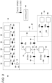
- Fig. 3 is a diagram illustrating a configuration of the separation device 40.
- the separation device 40 can separate a desired separation target from a cell liquid. Furthermore, the separation device 40 can perform some of treatments of the method for manufacturing the filter unit 12 illustrated in Fig. 2C .
- the separation device 40 includes a separation circuit 42 and a controller 44.
- the separation circuit 42 includes a supply unit 46, a separation unit 48, and a discharge unit 50.
- the supply unit 46 includes a cell liquid container 52, an avidin liquid container 54, a first antibody liquid container 56, a second antibody liquid container 58, a release liquid container 60, a cleaning liquid container 62, a first supply flow path 64 to a sixth supply flow path 74, valves 76a to 76f, and a pump 78.
- Each of the cell liquid container 52 to the cleaning liquid container 62 is, for example, a medical bag obtained by molding a soft resin material into a bag shape.
- Each of the cell liquid container 52 to the cleaning liquid container 62 may be a tank or the like made of a hard material.
- Each of the cell liquid container 52 to the cleaning liquid container 62 is detachable from the separation device 40.
- the cell liquid container 52 is filled with a cell liquid.
- the cell liquid is a solution containing two types of separation targets. In the present embodiment, the two types of separation targets are referred to as a first cell and a second cell.
- the avidin liquid container 54 is filled with an avidin liquid.
- the avidin liquid is a solution containing the avidin 32.
- the first antibody liquid container 56 is filled with a first antibody liquid.
- the first antibody liquid is a solution containing a first biotinylated antibody 36a ( Fig. 2C ) in which a first antibody 30a and a second biotin 34b bind to each other.
- the first antibody 30a can specifically bind to an antigen included in the first cell.
- the second antibody liquid container 58 is filled with a second antibody liquid.
- the second antibody liquid is a solution containing a second biotinylated antibody 36b ( Fig. 2C ) in which a second antibody 30b different from the first antibody 30a and the second biotin 34b bind to each other.
- the second antibody 30b can specifically bind to an antigen included in the second cell.
- the release liquid container 60 is filled with a release liquid.
- the release liquid is, for example, a deoxyribonuclease solution.
- the cleaning liquid container 62 is filled with a cleaning liquid.
- the cleaning liquid is, for example, water or phosphate buffered saline (PBS).
- the cell liquid container 52 is connected to a suction port 80 of the pump 78 via the first supply flow path 64.
- the first supply flow path 64 has the valve 76a.
- the avidin liquid container 54 is connected to the suction port 80 of the pump 78 via the second supply flow path 66.
- the second supply flow path 66 has the valve 76b.
- the first antibody liquid container 56 is connected to the suction port 80 of the pump 78 via the third supply flow path 68.
- the third supply flow path 68 has the valve 76c.
- the second antibody liquid container 58 is connected to the suction port 80 of the pump 78 via the fourth supply flow path 70.
- the fourth supply flow path 70 has the valve 76d.
- the release liquid container 60 is connected to the suction port 80 of the pump 78 via the fifth supply flow path 72.
- the fifth supply flow path 72 has the valve 76e.
- the cleaning liquid container 62 is connected to the suction port 80 of the pump 78 via the sixth supply flow path 74.
- the separation unit 48 includes the filter 10, an upstream flow path 84, a downstream flow path 86, a first bypass flow path 88, a second bypass flow path 90, and valves 92a to 92d.
- the filter 10 illustrated in Fig. 3 has two filter units 12. Each of the filter units 12 is detachable from the separation device 40. That is, the filter unit 12 can be replaced according to the type of a separation target.
- the separation unit 48 may be detachable from the separation device 40. Alternatively, the filter 10 may be detachable from the separation device 40.
- the filter 10 includes the first filter unit 12a, the second filter unit 12b, and the connection flow path 14.
- the inlet port 22 of the first filter unit 12a is connected to a discharge port 82 of the pump 78 via the upstream flow path 84.
- the upstream flow path 84 has the valve 92a.
- the upstream flow path 84 located on an upstream side of the valve 92a and the connection flow path 14 communicate with each other by the first bypass flow path 88.
- the first bypass flow path 88 has the valve 92b.
- the outlet port 24 of the second filter unit 12b is connected to the downstream flow path 86.
- the downstream flow path 86 has the valve 92c.
- the downstream flow path 86 located on a downstream side of the valve 92c and the connection flow path 14 communicate with each other by the second bypass flow path 90.
- the second bypass flow path 90 has the valve 92d.
- the discharge unit 50 includes a collection container 94, a waste liquid container 96, a collection flow path 98, a waste liquid flow path 100, and valves 102a and 102b.
- Each of the collection flow path 98 and the waste liquid flow path 100 is connected to the downstream flow path 86 of the separation unit 48.
- the collection flow path 98 has the valve 102a.
- the waste liquid flow path 100 has the valve 102b.
- the collection container 94 is connected to the outlet port 24 of the second filter unit 12b via the collection flow path 98 and the downstream flow path 86.
- the collection container 94 is connected to the outlet port 24 of the first filter unit 12a via the collection flow path 98, the downstream flow path 86, and the second bypass flow path 90.
- the waste liquid container 96 is connected to the outlet port 24 of the second filter unit 12b via the waste liquid flow path 100 and the downstream flow path 86.
- the waste liquid container 96 is connected to the outlet port 24 of the first filter unit 12a via the waste liquid flow path 100, the downstream flow path 86, and the second bypass flow path 90.
- the controller 44 includes a processing circuit and various memories (volatile memory, non-volatile memory, and the like).
- the processing circuit may be a processor such as a CPU.
- the processing circuit may be an integrated circuit such as an ASIC or an FPGA.
- the processor can execute various types of treatment by executing a program stored in the nonvolatile memory.
- Examples of the volatile memory include a RAM.
- the volatile memory is used as a working memory of the processor.
- the volatile memory temporarily stores data and the like necessary for treatment or computation.
- Examples of the nonvolatile memory include a ROM and a flash memory.
- the non-volatile memory is used as a storage memory.
- the nonvolatile memory stores a program, a table, a map, and the like.
- the controller 44 controls opening and closing of each valve of the separation circuit 42.
- the controller 44 also controls operation of the pump 78.
- the controller 44 can automatically perform a series of treatments illustrated in Fig. 4 by a program.
- Fig. 4 is a flowchart of a filter manufacturing treatment and a separation treatment performed using the separation device 40.
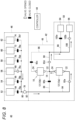
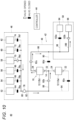
- Each of Figs. 5 to 13 is a diagram illustrating opening and closing of a valve of the separation device 40 and a flow of a liquid in the separation device 40 in each step.
- a black valve means a closed state
- a white valve means an opened state.
- Each step illustrated in Fig. 4 is performed by the controller 44 controlling each valve and the pump 78.
- a user performs the next preparation work in advance before the series of treatment illustrated in Fig. 4 .
- a user fills each filter unit 12 with the base materials 20 to each of which the first biotin 34a is fixed.
- the user manufactures the first antibody liquid containing the first biotinylated antibody 36a and fills the first antibody liquid container 56 with the first antibody liquid.
- the user manufactures the second antibody liquid containing the second biotinylated antibody 36b and fills the second antibody liquid container 58 with the second antibody liquid.
- the first biotinylated antibody 36a and the second biotinylated antibody 36b are substances which can bind to an unnecessary separation target (first cell or second cell) in the cell liquid.
- the user attaches the cell liquid container 52 to the cleaning liquid container 62 to the separation device 40.
- step S1 the controller 44 performs priming.
- the controller 44 brings the separation circuit 42 into the state illustrated in Fig. 5 . That is, the controller 44 opens the valve 76f, the valve 92a, the valve 92c, and the valve 102b and closes the other valves. Furthermore, the controller 44 operates the pump 78. Then, the cleaning liquid in the cleaning liquid container 62 flows through a path indicated by an arrow in Fig. 5 and is collected in the waste liquid container 96.
- the controller 44 brings the separation circuit 42 into the state illustrated in Fig. 6 . That is, the controller 44 opens the valve 76f, the valve 92b, the valve 92d, and the valve 102b and closes the other valves. Furthermore, the controller 44 operates the pump 78. Then, the cleaning liquid in the cleaning liquid container 62 flows through a path indicated by an arrow in Fig. 6 and is collected in the waste liquid container 96. The separation unit 48 is cleaned by the treatment in step S1.
- step S2 the controller 44 performs pre-coating (first pre-coating) of the avidin 32.
- the controller 44 brings the separation circuit 42 into the state illustrated in Fig. 7 . That is, the controller 44 opens the valve 76b, the valve 92a, the valve 92c, and the valve 102b and closes the other valves. Furthermore, the controller 44 operates the pump 78. Then, the avidin liquid in the avidin liquid container 54 flows through a path indicated by an arrow in Fig. 7 and is collected in the waste liquid container 96.
- the controller 44 operates the pump 78 for a predetermined time or more and then stops the pump 78 for a predetermined time or more.
- the avidin liquid is supplied to each filter unit 12, and the base material 20 in the filter unit 12 is immersed in the avidin liquid.
- the first biotin 34a fixed to the base material 20 binds to the avidin 32 in the avidin liquid.
- the avidin 32 is fixed to the base material 20.
- the controller 44 brings the separation circuit 42 into the state illustrated in Fig. 5 .
- a portion through which the avidin liquid flows is cleaned.
- step S3 the controller 44 performs pre-coating (second pre-coating) of the first biotinylated antibody 36a.
- the controller 44 brings the separation circuit 42 into the state illustrated in Fig. 8 . That is, the controller 44 opens the valve 76c, the valve 92a, the valve 92d, and the valve 102b and closes the other valves. Furthermore, the controller 44 operates the pump 78. Then, the first antibody liquid in the first antibody liquid container 56 flows through a path indicated by an arrow in Fig. 8 and is collected in the waste liquid container 96. The controller 44 operates the pump 78 for a predetermined time or more and then stops the pump 78 for a predetermined time or more.
- the first antibody liquid is supplied to the first filter unit 12a, and the base material 20 in the first filter unit 12a is immersed in the first antibody liquid.
- the avidin 32 fixed to the base material 20 binds to the first biotinylated antibody 36a in the first antibody liquid.
- the active group 28 (first biotin 34a, avidin 32, first biotinylated antibody 36a) is fixed to the surface 26 of the base material 20.
- the controller 44 brings the separation circuit 42 into the state illustrated in Fig. 9 . That is, the controller 44 opens the valve 76f, the valve 92a, the valve 92d, and the valve 102b and closes the other valves. Furthermore, the controller 44 operates the pump 78. Then, the cleaning liquid in the cleaning liquid container 62 flows through a path indicated by an arrow in Fig. 9 and is collected in the waste liquid container 96. By this treatment, a portion through which the first antibody liquid flows is cleaned.
- step S4 the controller 44 performs pre-coating (third pre-coating) of the second biotinylated antibody 36b.
- the controller 44 brings the separation circuit 42 into the state illustrated in Fig. 10 . That is, the controller 44 opens the valve 76d, the valve 92b, the valve 92c, and the valve 102b and closes the other valves. Furthermore, the controller 44 operates the pump 78. Then, the second antibody liquid in the second antibody liquid container 58 flows through a path indicated by an arrow in Fig. 10 and is collected in the waste liquid container 96. The controller 44 operates the pump 78 for a predetermined time or more and then stops the pump 78 for a predetermined time or more.
- the second antibody liquid is supplied to the second filter unit 12b, and the base material 20 in the second filter unit 12b is immersed in the second antibody liquid.
- the avidin 32 fixed to the base material 20 binds to the second biotinylated antibody 36b in the second antibody liquid.
- the active group 28 (first biotin 34a, avidin 32, and second biotinylated antibody 36b) is fixed to the surface 26 of the base material 20.
- the controller 44 brings the separation circuit 42 into the state illustrated in Fig. 11 . That is, the controller 44 opens the valve 76f, the valve 92b, the valve 92c, and the valve 102b and closes the other valves. Furthermore, the controller 44 operates the pump 78. Then, the cleaning liquid in the cleaning liquid container 62 flows through a path indicated by an arrow in Fig. 11 and is collected in the waste liquid container 96. By this treatment, the portion where the second antibody liquid flows is cleaned.
- step S5 the controller 44 separates a desired cell from the cell liquid.
- the controller 44 brings the separation circuit 42 into the state illustrated in Fig. 12 . That is, the controller 44 opens the valve 76a, the valve 92a, the valve 92c, and the valve 102a and closes the other valves. Furthermore, the controller 44 operates the pump 78. Then, the cell liquid in the cell liquid container 52 flows through a path indicated by the arrow in Fig. 12 and is collected in the collection container 94. The controller 44 operates the pump 78 until the cell liquid in the cell liquid container 52 disappears, and then stops the pump 78. By the treatment in step S5, the cell liquid is supplied to each filter unit 12, and the base material 20 in each filter unit 12 is immersed in the cell liquid.
- the first biotinylated antibody 36a fixed to the base material 20 of the first filter unit 12a binds to the antigen of the first cell in the cell liquid.
- the second biotinylated antibody 36b fixed to the base material 20 of the second filter unit 12b binds to the antigen of the second cell in the cell liquid.
- the controller 44 brings the separation circuit 42 into the state illustrated in Fig. 13 .
- cells remaining in the separation circuit 42 can be collected without waste. This is an end of the series of treatments.
- the separation device 40 performs so-called negative selection.
- the filter 10 may include another unit that physically separates a separation target.
- the other unit is made of a porous member and includes another base material different from that of the filter unit 12.
- a plurality of micropores formed in the other base material is larger than a separation target to be captured by the filter unit 12 and smaller than a separation target to be captured by the other unit.
- a polyurethane filter medium (manufactured by Terumo Corporation, product name: IMUGARD, thickness: 2 mm) was cut into a size of 15 cm ⁇ 5 cm to prepare a PU film.
- the PU film obtained in the above 1) was allowed to stand in a graft polymerization reaction chamber (plasma irradiation device, Pico Full PC, manufactured by DIENER ELECTRONIC, low pressure type), the chamber was evacuated, and 0.2 torr of Ar gas (100%) was introduced into the chamber.
- Plasma irradiation argon ionization gas plasma irradiation
- GMA glycidyl methacrylate
- PU film (GMA-PU film) (base material A-3) having GMA graft-polymerized on a surface thereof was obtained.
- the GMA-PU film obtained in the above section 1 was impregnated with an HMDA aqueous solution having the following composition, and incubated at 70°C overnight to cause an epoxy group of GMA to react with one amine group of hexamethylenediamine (HMDA) (HMDA-GMA-PU film) (base material A-4).
- HMDA hexamethylenediamine
- HMDA-GMA-PU film was impregnated with a 0.01 N-HCl aqueous solution for eight hours (impregnated HMDA-GMA-PU film).
- the impregnated HMDA-GMA-PU film was press-cleaned with a roller while the impregnated HMDA-GMA-PU film was impregnated with 2 L of ultrafiltered water (cleaned HMDA-GMA-PU film).
- HMDA-GMA-PU film The cleaned HMDA-GMA-PU film after the press cleaning was impregnated with a biotin aqueous solution having the following composition at room temperature (25°C) overnight to cause the other amine group of hexamethylenediamine (HMDA) to react with a carboxyl group of biotin (biotin-HMDA-GMA-PU film).
- HMDA hexamethylenediamine
- biotin-HMDA-GMA-PU film was press-cleaned with a roller while the biotin-HMDA-GMA-PU film was impregnated with 2 L of ultrafiltered water (cleaned biotin-HMDA-GMA-PU film).
- Sample 1 obtained in the above section 2 was punched out to a diameter of 1 mm ( ⁇ 1 mm).
- Tween-20 0.05 (w/v)% was added to 10 mL of PBS to prepare T-PBS.
- Streptavidin-FITC (manufactured by Funakoshi Co., Ltd., trade name: labeled streptavidin (Streptavidin Conjugates), hereinafter "StA-F") was added to 2 mL of PBS at a concentration of 5 ⁇ g/mL to prepare StA-F-PBS.
- Sample 1 having a diameter of 1 mm was set in a commercially available filter housing (manufactured by EMD Millipore Corp., trade name: SWINNEX), primed well with T-PBS, and air bubbles in the housing were removed.
- SWINNEX commercially available filter housing
- StA-F not fixed onto sample 1 was cleaned and removed with 30 mL of T-PBS, and then sample 1 was taken out from the housing (measurement sample 1).
- Fluorescence observation of measurement sample 1 obtained above was performed under the following conditions using a confocal laser scanning microscope (manufactured by Olympus Corporation, product name: FV3000).
- Results are illustrated in Fig. 15 .
- sample 1 emitted fluorescence uniformly. From this result, it can be seen that in sample 1, biotin is uniformly fixed onto the polyurethane filter medium.
- Example 2 Five biotin-HMDA-GMA-PU films (sample 2) were manufactured in a similar manner to Example 1 except that the polyurethane filter medium (manufactured by Terumo Corporation, product name: IMUGARD, thickness: 2 mm) was cut into a size of 25 mm in diameter ( ⁇ ) in Example 1.
- the polyurethane filter medium manufactured by Terumo Corporation, product name: IMUGARD, thickness: 2 mm
- cell capture was evaluated according to the following method using a filter 200 illustrated in Fig. 16 .
- Fig. 16 is a schematic diagram illustrating a cell capture evaluating test device.
- samples 220 as samples 2 were stacked with a silicone spacer 231 (donut shape with inner diameter: 24 mm, outer diameter: 29 mm, and thickness: 1.0 mm) interposed therebetween, and then a polypropylene (PP) mesh (diameter ( ⁇ ): 21 mm, thickness: 0.5 mm, mesh size: 1.7 mm ⁇ 1.7 mm)230 was placed at a central portion of each of an uppermost sample 220a as sample 2 and a lowermost sample 220b as sample 2 to prepare a filter unit 212.
- the filter unit 212 was disposed in a container 218 in which tubes 223 and 225 were connected to a lower part thereof and an upper part thereof via tube connectors 222 and 224, respectively, to assemble the filter 200.
- PBS buffer phosphate buffer, composition: sodium chloride 136.89 mM, potassium chloride 2.68 mM, potassium dihydrogen phosphate 0.147 mM, and disodium hydrogen phosphate (anhydrous) 9.58 mM
- PBS buffer phosphate buffer, composition: sodium chloride 136.89 mM, potassium chloride 2.68 mM, potassium dihydrogen phosphate 0.147 mM, and disodium hydrogen phosphate (anhydrous) 9.58 mM
- StA streptavidin
- PBS solution 0.05% (w/v) streptavidin (hereinafter, also referred to as "StA")/PBS solution
- StA/PBS solution 0.05% (w/v) streptavidin (hereinafter, also referred to as "StA")/PBS solution
- 5 mL of this StA solution was injected from the lower tube 223 of the filter 200 into the filter 200 at a flow rate of 1 mL/min using a syringe pump. After injection of the StA/PBS solution, the upper tube 225 and the lower tube 223 of the filter 200 were clamped. In this state, incubation was performed at 37°C for 15 minutes.
- a porcine CD8 antibody to which biotin bound (manufactured by Thermo Fisher Scientific, product name: Invitrogen, CD8 alpha Monoclonal Antibody (76-2-11), Biotin) was added to PBS so as to have a concentration of 0.005% (w/v) to prepare a porcine CD8 antibody/PBS solution.
- 5 mL of the porcine CD8 antibody/PBS solution was injected from the lower tube 223 of the filter 200 into the filter 200 at a flow rate of 1 mL/min using a syringe pump. After the injection of the porcine CD8 antibody/PBS solution, the upper tube 225 and the lower tube 223 of the filter 200 were clamped. In this state, incubation was performed at 37°C for 15 minutes.
- CPD liquid composition: sodium citrate hydrate 26.30 g, citric acid hydrate 3.27 g, glucose 23.20 g, sodium dihydrogen phosphate 2.51 g/1,000 mL water for injection
- Incubation was performed for a predetermined time in the above section 2, and then 5 mL of the whole pig blood (CPD blood collection) was injected from the lower tube 223 of the filter 200 into the filter 200 at a flow rate of 1 mL/min using a syringe pump. After the injection of the whole pig blood (CPD blood collection), the upper tube 225 and the lower tube 223 of the filter 200 were clamped. In this state, incubation was performed at 37°C for 15 minutes.
- PBS buffer was injected from the lower tube 223 of the filter 200 into the filter 200 at a flow rate of 1 mL/min using a syringe pump, and 5 mL of the pig whole blood in the filter 200 was collected.
- CD 8 positive cell capture ratio 1 ⁇ Number of CD 8 positive cells in blood after collection Number of CD 8 positive cells in blood after injection ⁇ 100 %
- a polyurethane filter medium manufactured by Terumo Corporation, product name: IMUGARD, thickness: 2 mm
- IMUGARD thickness: 2 mm
- five comparative PU films Comparative Example 1
- a CD8 positive cell capture ratio was calculated in a similar manner to Example 2 except that the comparative PU film was used instead of sample 2 in Example 2.
- sample 2 (Example 2) captured significantly more cells than the comparative PU film (Comparative Example 1).
Landscapes
- Chemical & Material Sciences (AREA)
- Analytical Chemistry (AREA)
- Chemical Kinetics & Catalysis (AREA)
- Organic Chemistry (AREA)
- Health & Medical Sciences (AREA)
- Life Sciences & Earth Sciences (AREA)
- Engineering & Computer Science (AREA)
- Molecular Biology (AREA)
- General Health & Medical Sciences (AREA)
- Biochemistry (AREA)
- Immunology (AREA)
- Physics & Mathematics (AREA)
- Medicinal Chemistry (AREA)
- Biomedical Technology (AREA)
- Hematology (AREA)
- Urology & Nephrology (AREA)
- Nanotechnology (AREA)
- Pathology (AREA)
- Food Science & Technology (AREA)
- General Physics & Mathematics (AREA)
- Inorganic Chemistry (AREA)
- Biophysics (AREA)
- Plasma & Fusion (AREA)
- Manufacturing & Machinery (AREA)
- Genetics & Genomics (AREA)
- Proteomics, Peptides & Aminoacids (AREA)
- Biotechnology (AREA)
- Cell Biology (AREA)
- Microbiology (AREA)
- Apparatus Associated With Microorganisms And Enzymes (AREA)
- Solid-Sorbent Or Filter-Aiding Compositions (AREA)
Abstract
Description
- The present invention relates to a filter that captures a cell or a protein contained in a liquid, and a method for manufacturing the filter.
- Examples of a method for separating a cell from a cell suspension include a method using a filter and a centrifugation method. For example,
JP 2011-24575 A - Some cell suspensions contain a plurality of types of cells having similar sizes. In a method using a filter having fine pores and a centrifugation method, it is difficult to separate a specific cell from a plurality of types of cells having similar sizes.
- An object of the present invention is to solve the above-described problem.
- The filter of the present invention is (1) a filter that captures a separation target by causing a liquid containing a cell or a protein as the separation target to pass through the filter, the filter including: a base material made of a porous polyurethane having a plurality of micropores; and an active group fixed to a surface of the base material and capable of specifically binding to the separation target.
- According to the above configuration, a specific cell can be separated from a plurality of types of cells having similar sizes contained in a cell liquid, and similarly, a specific protein can be separated from a plurality of types of proteins having similar sizes.
- (2) In the filter of (1), the active group preferably includes an antibody or an aptamer capable of specifically binding to an antigen included in the separation target.
- (3) In the filter of (2), the active group preferably includes a conjugate in which the antibody or the aptamer binds to biotin, and a biotin-binding protein fixed to the base material and capable of binding to the biotin.
- (4) In the filter according to (2) or (3), the active group preferably includes a conjugate in which the antibody or the aptamer binds to first biotin, second biotin fixed to the base material, and a biotin-binding protein capable of binding to each of the first biotin and the second biotin.
- (5) In the filter according to (4), preferably, the second biotin is fixed to the base material via a constituent unit A derived from a compound A having an epoxy group and an ethylenically unsaturated group and a constituent unit B derived from a diamine compound B binding to the constituent unit A, the constituent unit A binds to the base material, and the constituent unit B binds to the second biotin.
- (6) In the filter according to (5), the compound A is preferably at least one selected from the group consisting of glycidyl acrylate, glycidyl methacrylate (GMA), 3,4-epoxycyclohexyl methyl acrylate, 3,4-epoxycyclohexyl methyl methacrylate, β-methyl glycidyl acrylate, and β-methyl glycidyl methacrylate.
- (7) In the filter according to (5) or (6), the compound B is preferably at least one selected from the group consisting of ethylenediamine, trimethylenediamine, 1,2-diaminopropane, tetramethylenediamine, 1,3-diaminobutane, 2,3-diaminobutane, pentamethylenediamine, 2,4-diaminopentane, hexamethylenediamine (HMDA), octamethylenediamine, nonamethylenediamine, decamethylenediamine, undecamethylenediamine, dodecamethylenediamine, tridecamethylenediamine, octadecamethylenediamine, xylylenediamine, and phenylenediamine.
- (8) The filter according to any one of (1) to (7) preferably includes a container that accommodates a plurality of the base materials to which the active group is fixed, in which a plurality of the base materials are stacked in the container from an upstream side to a downstream side of a flow of the liquid.
- According to the above configuration, the cell liquid can be brought into contact with each of the base materials.
- (9) The filter of (8) preferably includes a plurality of the containers arranged in a line from the upstream side to the downstream side of the flow of the liquid, in which a type of the active group fixed to the base material is different among the containers.
- According to the above configuration, a plurality of types of separation targets can be separated by flowing the cell liquid through the filter once.
- (10) In the filter according to any one of (1) to (9), each of a plurality of the micropores formed in the base material is preferably larger than the separation target.
- According to the above configuration, clogging of the filter can be prevented. In addition, according to the above configuration, a collection ratio of a target cell can be improved.
- (11) The filter according to any one of (1) to (10) preferably includes another base material made of a porous member and different from the base material, in which each of a plurality of micropores formed in the other base material is larger than the separation target and smaller than another separation target different from the separation target.
- According to the above configuration, a substance having a large size contained in the cell liquid can be separated.
- The method for manufacturing a filter according to the present invention includes: (1) irradiating at least a part of a surface of a base material made of a porous polyurethane having a plurality of micropores with plasma, (2) bringing a compound A having an epoxy group and an ethylenically unsaturated group into contact with the base material after the plasma irradiation to bind the compound A to the base material; (3) bringing a diamine compound B into contact with the base material after the compound A is brought into contact with the base material to bind (fix) the diamine compound B to the surface of the base material via a constituent unit A derived from the compound A; and (4) bringing biotin into contact with the surface of the base material after the diamine compound B is brought into contact with the base material to bind the biotin to the surface of the base material via the constituent unit A derived from the compound A and the diamine compound B.
-
-
Fig. 1 is a diagram illustrating a configuration of a filter. -
Figs. 2A to 2C are partially enlarged diagrams of a filter unit. -
Fig. 3 is a diagram illustrating a configuration of a separation device. -
Fig. 4 is a flowchart of a filter manufacturing treatment and a separation treatment performed using the separation device. -
Fig. 5 is a diagram illustrating opening and closing of a valve of the separation device and a flow of a liquid in the separation device in steps S1, S2, and S5 ofFig. 4 . -
Fig. 6 is a diagram illustrating opening and closing of the valve of the separation device and a flow of the liquid in the separation device in step S1 ofFig. 4 . -
Fig. 7 is a diagram illustrating opening and closing of the valve of the separation device and a flow of the liquid in the separation device in step S2 ofFig. 4 . -
Fig. 8 is a diagram illustrating opening and closing of the valve of the separation device and a flow of the liquid in the separation device in step S3 ofFig. 4 . -
Fig. 9 is a diagram illustrating opening and closing of the valve of the separation device and a flow of the liquid in the separation device in step S3 ofFig. 4 . -
Fig. 10 is a diagram illustrating opening and closing of the valve of the separation device and a flow of the liquid in the separation device in step S4 ofFig. 4 . -
Fig. 11 is a diagram illustrating opening and closing of the valve of the separation device and a flow of the liquid in the separation device in step S4 ofFig. 4 . -
Fig. 12 is a diagram illustrating opening and closing of the valve of the separation device and a flow of the liquid in the separation device in step S5 ofFig. 4 . -
Fig. 13 is a diagram illustrating opening and closing of the valve of the separation device and a flow of the liquid in the separation device in a cell collection step. -
Fig. 14 is a diagram for describing fixation of an active group capable of specifically binding to a separation target according to the present invention. -
Fig. 15 is a fluorescent photograph indicating presence of biotin insample 1 in Example 1. -
Fig. 16 is a schematic diagram illustrating a cell capture evaluating test device. - One aspect of the present invention provides a filter that captures a separation target by causing a liquid containing a cell or a protein as the separation target to pass through the filter, the filter including: a base material made of a porous polyurethane having a plurality of micropores; and an active group fixed to a surface of the base material and capable of specifically binding to the separation target. According to the present invention, a specific cell can be separated from a plurality of types of cells having similar sizes, and similarly, a specific protein can be separated from a plurality of types of proteins having similar sizes.
- Hereinafter, embodiments for carrying out the present invention will be described in detail. Note that the present invention is not limited only to the following embodiments, and various modifications can be made within the scope of claims. In addition, the embodiments described in the present specification can be arbitrarily combined with each other to form another embodiment.
- Throughout the present specification, expression of a singular should be understood to include also a concept of a plural thereof unless otherwise stated. Thus, an article of a singular (for example, "a", "an", and "the" in English) should be understood to include also a concept of a plural thereof unless otherwise stated. In addition, terms used in the present specification should be understood to be used in a sense commonly used in the art unless otherwise stated. Therefore, unless otherwise defined, all technical and scientific terms used in the present specification have the same meanings as commonly understood by a person skilled in the art to which the present invention belongs. In a case of contradiction, priority is given to the present specification (including definitions).
- In addition, in the present specification, a range from "X to Y" includes X and Y, and indicates "X or more and Y or less". Unless otherwise specified, operations and measurements of physical properties and the like are performed at room temperature (20 to 25°C) and at relative humidity of 40 to 60% RH.
- In the present specification, the term "(meth)acryl" represents both acryl and methacryl. Therefore, for example, the term "(meth)acrylic acid" encompasses both acrylic acid and methacrylic acid. Similarly, the term "(meth)acryloyl" encompasses both acryloyl and methacryloyl. Therefore, for example, the term "(meth)acryloyl group" encompasses both an acryloyl group and a methacryloyl group.
- In the present specification, "A and/or B" means both A and B, or either A or B.
- In addition, in the present specification, when a constituent unit is defined to be "derived" from a certain monomer, it means that the constituent unit is a divalent constituent unit generated by cleavage of one bond of a polymerizable unsaturated double bond of the corresponding monomer.
-
Fig. 1 is a diagram illustrating a configuration of afilter 10. Thefilter 10 introduces a liquid from an inlet, captures one or more types of separation targets contained in the liquid, and discharges the liquid from an outlet. The liquid is, for example, a cell suspension (cell liquid). The separation target is a cell or a protein. Thefilter 10 includes one ormore filter units 12. Thefilter 10 illustrated inFig. 1 includes two filter units 12 (afirst filter unit 12a and asecond filter unit 12b). - The two
filter units 12 are arranged in a line from an upstream side to a downstream side of a flow of a liquid introduced into thefilter 10 such that the liquid passes through thefilter units 12 in turn. InFig. 1 , the liquid flows from bottom to top. A separation target captured by thefirst filter unit 12a is different from a separation target captured by thesecond filter unit 12b. Each of thefilter units 12 includes acontainer 18 and a plurality ofbase materials 20. - The
container 18 accommodates a plurality of thebase materials 20. Thecontainer 18 has aninlet port 22 and anoutlet port 24. Theinlet port 22 can introduce the liquid from the outside to the inside of thecontainer 18. Theinlet port 22 of thefirst filter unit 12a corresponds to an inlet of thefilter 10. Theoutlet port 24 can discharge the liquid from the inside to the outside of thecontainer 18. Theoutlet port 24 of thesecond filter unit 12b corresponds to an outlet of thefilter 10. Theoutlet port 24 of thefirst filter unit 12a and theinlet port 22 of thesecond filter unit 12b communicate with each other by aconnection flow path 14. - Note that, as illustrated in
Fig. 3 , by joining of another flow path (first bypass flow path 88) to theconnection flow path 14, theinlet port 22 of thesecond filter unit 12b can be an inlet of thefilter 10. As illustrated inFig. 3 , branching of another flow path (second bypass flow path 90) from theconnection flow path 14, theoutlet port 24 of thefirst filter unit 12a can be an outlet of thefilter 10. - A plurality of the
base materials 20 is filled in thecontainer 18. The plurality ofbase materials 20 is stacked in a thickness direction of thebase materials 20. Furthermore, a stacking direction of a plurality of the base materials 20 (thickness direction of the base materials 20) is the same as a direction from theinlet port 22 toward theoutlet port 24. That is, a plurality of thebase materials 20 is arranged in a line from an upstream side to a downstream side of a flow of the liquid. -
Figs. 2A to 2C are partially enlarged diagrams of thefilter unit 12. Each of the drawings schematically illustrates asurface 26 of thebase material 20 and anactive group 28. Thesurface 26 of thebase material 20 refers to a portion of thebase material 20 that can be in contact with a liquid passing through thefilter unit 12. - The
base material 20 is made of a porous polyurethane having a plurality of micropores. According to the porous polyurethane, a surface area of thebase material 20 can increase. - The
active group 28 capable of specifically binding to a separation target is fixed to thesurface 26 of thebase material 20. Theactive group 28 includes anantibody 30 capable of specifically binding to an antigen included in the separation target. Note that theactive group 28 may include an aptamer instead of theantibody 30. - For example, as in the
filter unit 12 illustrated inFig. 2A , theantibody 30 may be directly fixed to thesurface 26 of thebase material 20. Alternatively, as in thefilter unit 12 illustrated inFig. 2B , abiotinylated antibody 36 in which theantibody 30 andbiotin 34 bind to each other and avidin 32 (biotin-binding protein) may be used. For example, thebiotinylated antibody 36 may be fixed to thesurface 26 of thebase material 20 via theavidin 32. Note that another biotin-binding protein such as streptavidin may be used instead of theavidin 32. In thefilter unit 12 illustrated inFig. 2B , theavidin 32 is directly fixed to thesurface 26 of thebase material 20. Furthermore, theavidin 32 and thebiotinylated antibody 36 bind to each other. - As in the
filter unit 12 illustrated inFig. 2C , thebiotinylated antibody 36 in which theantibody 30 and a second biotin 34b bind to each other, the avidin 32 (biotin-binding protein), and afirst biotin 34a may be used. For example, thebiotinylated antibody 36 may be fixed to thesurface 26 of thebase material 20 via theavidin 32 and thefirst biotin 34a. In thefilter unit 12 illustrated inFig. 2C , thefirst biotin 34a is directly fixed to thesurface 26 of thebase material 20. Furthermore, thefirst biotin 34a and theavidin 32 bind to each other. In addition, theavidin 32 and thebiotinylated antibody 36 bind to each other. - According to the
filter units 12 illustrated inFigs. 2A to 2C , when a cell liquid flows from theinlet port 22 toward theoutlet port 24 of thefilter unit 12, theantibody 30 of theactive group 28 binds to an antigen included in a separation target in the cell liquid. The type of theantibody 30 is selected in advance according to the type of the separation target. As a result, while the separation target in the cell liquid is captured by thebase material 20, the cell liquid containing substances other than the separation target is discharged from theoutlet port 24 to the outside of thefilter unit 12. - As described above, a porous polyurethane is used as the
base material 20 of thefilter 10. Generally, the porous polyurethane is used as a leukocyte removing filter. Micropores of the porous polyurethane used as thebase material 20 are larger than micropores of the leukocyte removing filter. A size of the micropore of the porous polyurethane is adjusted so as to be larger than that of a separation target contained in a cell liquid. The porous polyurethane is cut into a size that can be accommodated in thecontainer 18 to be used as thebase material 20. Theactive group 28 is fixed to thesurface 26 of thecut base material 20 by the following manufacturing method. - The
filter unit 12 illustrated inFig. 2A can be manufactured, for example, as follows. Thecut base material 20 and acrylic acid are subjected to a plasma treatment. As a result, an acrylic group is introduced into thesurface 26 of thebase material 20. Next, a coupling agent (hexamethylenediamine) and theantibody 30 are reacted with the acrylic group on thesurface 26 of thebase material 20. Alternatively, thecut base material 20 and a compound having an epoxy group (preferably a glycidyl group), such as glycidyl (meth)acrylate, are subjected to a plasma treatment. As a result, an epoxy group (preferably a glycidyl group) is introduced into thesurface 26 of thebase material 20. Next, a coupling agent (hexamethylenediamine) and theantibody 30 are reacted with the epoxy group (preferably glycidyl group) on thesurface 26 of thebase material 20. - As a result, as illustrated in
Fig. 2A , the active group 28 (antibody 30) is fixed to thesurface 26 of thebase material 20. Thebase materials 20 to each of which theactive group 28 is fixed are stacked and filled in thecontainer 18. Through the above treatment, thefilter unit 12 illustrated inFig. 2A is manufactured. - The
filter unit 12 illustrated inFig. 2B can be manufactured, for example, as follows. Thecut base material 20 and acrylic acid are subjected to a plasma treatment. As a result, an acrylic group is introduced into thesurface 26 of thebase material 20. Next, a coupling agent (hexamethylenediamine) and theavidin 32 are reacted with the acrylic group on thesurface 26 of thebase material 20. Alternatively, thecut base material 20 and a compound having an epoxy group (preferably a glycidyl group), such as glycidyl (meth)acrylate, are subjected to a plasma treatment. As a result, an epoxy group (preferably a glycidyl group) is introduced into thesurface 26 of thebase material 20. Next, a coupling agent (hexamethylenediamine) and theavidin 32 are reacted with the epoxy group (preferably glycidyl group) on thesurface 26 of thebase material 20. As a result, theavidin 32 is fixed to thesurface 26 of thebase material 20. - The
base materials 20 to each of which theavidin 32 is fixed are stacked and filled in thecontainer 18. Next, an antibody liquid is introduced into thecontainer 18. The antibody liquid includes thebiotinylated antibody 36. Theavidin 32 fixed to thebase material 20 and thebiotinylated antibody 36 in the antibody liquid bind to each other. As a result, as illustrated inFig. 2B , the active group 28 (avidin 32 and biotinylated antibody 36) is fixed to thesurface 26 of thebase material 20. Through the above treatment, thefilter unit 12 illustrated inFig. 2B is manufactured. - The
filter unit 12 illustrated inFig. 2B can also be manufactured, for example, as follows. Thecut base material 20 is subjected to a plasma treatment. As a result, thesurface 26 of thebase material 20 is in an active state. Next, thebase material 20 is immersed in a solution of a compound having an epoxy group (preferably a glycidyl group), such as glycidyl methacrylate (GMA) or glycidyl acrylate. Alternatively, thebase material 20 is brought into contact with a gas of a compound having an epoxy group (preferably a glycidyl group), such as glycidyl methacrylate (GMA) or glycidyl acrylate. As a result, the compound such as GMA binds to thesurface 26 of thebase material 20. Next, a coupling agent (hexamethylenediamine) and theavidin 32 are reacted with a (meth)acrylic group or the epoxy group on thesurface 26 of thebase material 20. As a result, theavidin 32 is fixed to thesurface 26 of thebase material 20. A series of treatments after theavidin 32 is fixed is the same as the series of treatments after theavidin 32 is fixed in themanufacturing method 2. - The
filter unit 12 illustrated inFig. 2C can be manufactured, for example, as follows. Thesurface 26 of thecut base material 20 is coated with a polymer having thefirst biotin 34a binding thereto. As a result, thefirst biotin 34a is fixed to thesurface 26 of thebase material 20. Thebase materials 20 to each of which thefirst biotin 34a is fixed are stacked and filled in thecontainer 18. Next, an avidin liquid is introduced into thecontainer 18. The avidin liquid contains theavidin 32. Thefirst biotin 34a fixed to thebase material 20 and theavidin 32 in the avidin liquid bind to each other. As a result, theavidin 32 is fixed to thesurface 26 of thebase material 20. A series of treatments after theavidin 32 is fixed is the same as the series of treatments after theavidin 32 is fixed in themanufacturing method 2. - The
filter unit 12 illustrated inFig. 2C can be also manufactured, for example, as follows. Here, in thefilter unit 12 illustrated inFig. 2C , the active group includes a conjugate in which the antibody or the aptamer binds to second biotin, first biotin fixed to the base material, and a biotin-binding protein capable of binding to each of the first biotin and the second biotin. - Here, the
first biotin 34a inFig. 2C (second biotin in claims) is preferably fixed to the base material via a constituent unit A derived from a compound A having an epoxy group and an ethylenically unsaturated group and a constituent unit B derived from a diamine compound B binding to a terminal of the constituent unit A. - That is, in a preferred embodiment of the present invention, a filter is provided in which the second biotin is fixed to the base material via a constituent unit A derived from a compound A having an epoxy group and an ethylenically unsaturated group and a constituent unit B derived from a diamine compound B binding to a terminal of the constituent unit A, the constituent unit A binds to the base material, and the constituent unit B binds to the second biotin.
- The
filter unit 12 having such a structure is preferably manufactured by (1) irradiating at least a part of a surface of the base material with plasma (irradiation step), (2) bringing the compound A having an epoxy group and an ethylenically unsaturated group into contact with the base material after the plasma irradiation to bind (fix) the compound A to the base material (compound A fixing step); (3) bringing the diamine compound B into contact with the base material after the compound A is brought into contact with the base material to bind (fix) the diamine compound B to the surface of the base material via the constituent unit A derived from the compound A (diamine compound B fixing step); and (4) bringing biotin (second biotin in claims,first biotin 34a inFig. 2C ) into contact with the surface of the base material after the diamine compound B is brought into contact with the surface of the base material to bind (fix) the biotin to the surface of the base material via the constituent unit A derived from the compound A and the diamine compound B (biotin fixing step). - Therefore, the present invention also provides a method for manufacturing a filter, the method including: (1) irradiating at least a part of a surface of a base material made of a porous polyurethane having a plurality of micropores with plasma, (2) bringing the compound A having an epoxy group and an ethylenically unsaturated group into contact with the base material after the plasma irradiation to bind (fix) the compound A to the base material; (3) bringing the diamine compound B into contact with the base material after the compound A is brought into contact with the base material to bind (fix) the diamine compound B to the surface of the base material via the constituent unit A derived from the compound A; and (4) bringing biotin (second biotin in claims,
first biotin 34a inFig. 2C ) into contact with the surface of the base material after the diamine compound B is brought into contact with the surface of the base material to bind (fix) the biotin to the surface of the base material via the constituent unit A derived from the compound A and the diamine compound B. - Hereinafter, the above manufacturing method will be described in detail with reference to
Fig. 14 . - In this step, at least a part of a surface of a base material (base material 20) made of a porous polyurethane having a plurality of micropores is irradiated with plasma. Here, a reason why "at least a part of a surface of a base material is irradiated with plasma" is that it is not always necessary to fix biotin (therefore, an antibody or an aptamer) to all surfaces of the base material (entire surface) in some applications, and it is only required to fix biotin (therefore, an antibody or an aptamer) only to a surface portion (which may be a part or the whole) where it is required to capture a desired cell. Therefore, the plasma irradiation portion preferably includes at least a surface portion where it is required to capture a desired cell, and more preferably substantially includes a surface portion where it is required to capture a desired cell. Note that the phrase "the plasma irradiation portion substantially includes a surface portion where it is required to capture a desired cell" means that the plasma irradiation portion is preferably slightly larger than a surface where it is required to capture the desired cell, and preferably about 0.5 mm or more larger, and more preferably about 10 to 20 mm larger than a margin (outermost circumference) of the surface in order to more reliably capture the desired cell.
- The
base material 20 is cut into a predetermined size (base material A-1). Here, the base material is made of a porous polyurethane having a plurality of micropores. The size of the base material is not particularly limited, and can be appropriately selected according to an application. - Next, the cut base material (base material A-1) is subjected to a plasma treatment (base material A-2). As a result, a surface of the base material A-1 is in an active state. Therefore, when the surface of the base material A-1 is brought into contact with a compound A having an ethylenically unsaturated group in a next step, the compound A is graft-polymerized with the base material A-1. As a result, the compound A can firmly bind (fixed) to the
base material 20. Note that a desired plasma treatment can be performed even on a narrow inner surface having a small diameter, and therefore the plasma irradiation step is preferably performed by an ionization gas plasma treatment. - Before the surface of the base material A-1 is irradiated with plasma, the surface of the base material may be cleaned by an appropriate method. The cleaning method is not particularly limited, and can be performed by cleaning the surface with an appropriate solvent (for example, ultrasonic cleaning, a method for immersing the surface in a cleaning solvent, or a method for pouring a cleaning solvent over the surface).
- A pressure condition in the plasma treatment is not particularly limited, and can be either reduced pressure or atmospheric pressure. When the base material is tubular, the entire circumference of the base material (object to be treated) may be uniformly subjected to the plasma treatment without unevenness by irradiating the base material with a plasma gas while rotating a plasma irradiation nozzle around the base material (object to be treated) by one turn.
- An ionization gas that can be used for the plasma treatment is one or more gases selected from the group consisting of helium, neon, argon, krypton, air, oxygen, carbon dioxide, carbon monoxide, water vapor, nitrogen, hydrogen, and the like. The plasma treatment is preferably performed in an atmosphere substantially not containing oxygen, and more preferably performed in an atmosphere of at least one inert gas selected from the group consisting of helium, argon, and nitrogen. As a result, the compound A can more efficiently bind (be graft-polymerized) to the base material in a next step. Here, the "atmosphere substantially not containing oxygen" means that the amount of oxygen in the atmosphere is less than 3% by volume, and preferably 0.1% by volume or less. The above atmosphere can be adjusted by introducing a sufficient amount of a predetermined gas into a plasma irradiation device.
- Note that plasma treatment conditions (irradiation time, LF output, overcurrent, gas flow rate, gap between electrodes, and plasma irradiation distance) are not particularly limited, and can be appropriately selected according to a binding property (ease of fixation) between the compound A and the base material, the type and area of the base material to be used, and the like.
- As an example, irradiation time in the plasma treatment is preferably 5 to 60 seconds, and particularly preferably 10 to 40 seconds. Under such conditions, a sufficient amount of the compound A can be bound (fixed) to the surface of the base material.
- As an example, the LF output in the plasma treatment is preferably 100 to 500 W.
- As an example, the gas pressure in the plasma treatment is preferably 20 to 60 Pa.
- The temperature of the object to be treated (porous polyurethane base material) in the plasma treatment is not particularly limited, and heating or cooling may be performed in addition to room temperature. The plasma treatment is preferably performed at a temperature at which a heating device or a cooling device is unnecessary (for example, 5 to 35°C) from an economical point of view.
- The plasma irradiation device (system) that can be used for the plasma treatment is not particularly limited. Examples thereof include a plasma irradiation device (system) including a plasma generation tube that generates plasma by introducing gas molecules and exciting the gas molecules, and an electrode that excites the gas molecules in the plasma generation tube, in which plasma is emitted from one end of the plasma generation tube, but are not limited to such a configuration (system) at all.
- Examples thereof include devices adopting a high frequency induction method, a capacity-coupled electrode method, a corona discharge electrode-plasma jet method, a parallel plate type, a remote plasma type, an atmospheric pressure plasma type, a low pressure plasma type, and an ICP type high density plasma type. In addition, an ionization gas plasma irradiation device (system), particularly a plasma irradiation device (system) at atmospheric pressure can be used from among those already commercially available. Specifically, a plasma irradiation device manufactured by TRI-STAR TECHNOLOGIES: DURADYNE (product name or trade name), a plasma irradiation device manufactured by DIENER ELECTRONIC: PLASMABEAM, a plasma irradiation device manufactured by DIENER ELECTRONIC: Pico Full PC, or the like can be used, but the plasma irradiation device is not limited thereto at all.
- In this step, a compound A having an epoxy group and an ethylenically unsaturated group is brought into contact with the base material (base material A-2) that has been irradiated with plasma in the irradiation step. As a result, the compound A is graft-polymerized on the base material in an active state, and the compound A binds (is fixed) to the base material A-2 (base material A-3). Note that, in the present specification, the compound A having an epoxy group and an ethylenically unsaturated group is also simply referred to as "compound A ".
- The compound A only needs to have an epoxy group and an ethylenically unsaturated group, and preferably has a glycidyl group and an ethylenically unsaturated group. Examples of such a compound A include a (meth)acrylate having a glycidyl group (epoxy group), such as glycidyl acrylate, glycidyl methacrylate (GMA), 3,4-epoxycyclohexylmethyl acrylate, 3,4-epoxycyclohexylmethyl methacrylate, β-methylglycidyl acrylate, or β-methylglycidyl methacrylate; and a vinyl ether having a glycidyl group (epoxy group), such as allyl glycidyl ether, but are not limited thereto. Among these compounds, the compound A preferably contains at least one selected from the group consisting of glycidyl acrylate, glycidyl methacrylate (GMA), 3,4-epoxycyclohexyl methyl acrylate, 3,4-epoxycyclohexyl methyl methacrylate, β-methyl glycidyl acrylate, and β-methyl glycidyl methacrylate from a viewpoint of, for example, further improving a binding property to the porous polyurethane base material (graft polymerizability with the base material). The compound A is more preferably at least one selected from the group consisting of glycidyl acrylate, glycidyl methacrylate (GMA), 3,4-epoxycyclohexyl methyl acrylate, 3,4-epoxycyclohexyl methyl methacrylate, β-methyl glycidyl acrylate, and β-methyl glycidyl methacrylate. The compound A still more preferably contains at least one selected from the group consisting of glycidyl acrylate and glycidyl methacrylate. The compound A particularly preferably contains glycidyl acrylate or glycidyl methacrylate, particularly preferably contains glycidyl methacrylate, and is most preferably glycidyl methacrylate. The compound A may be used singly or in combination of two or more types thereof. When two or more types of compounds A are used, constituent units A may be arranged in a block form or randomly.
- In this step, as a specific method for bringing the compound A into contact with the base material (base material A-2) after plasma irradiation, either a method for bringing the compound A into contact with the base material A-2 as it is or a method for preparing a compound A solution in which the compound A is dissolved in a solvent and then bringing the compound A solution into contact with the base material A-2 may be used. It is preferable to bring the compound A into contact with the base material A-2 as it is, and it is more preferable to bring the gaseous compound A into contact with the base material A-2 from a viewpoint of, for example, further improving contact efficiency (graft polymerization efficiency) between the base material A-2 and the compound A. The contact between the compound A and the base material A-2 at this time can be performed, for example, by introducing the compound A separately placed under reduced pressure into a plasma irradiation device while the plasma irradiation device is in a reduced pressure state.
- In addition, in the method for bringing the compound A solution into contact with the base material A-2, a solvent to be used in dissolving the compound A is not particularly limited, and is appropriately selected according to the type of the compound A. Water (reverse osmosis membrane water (RO water), pure water, deionized water, distilled water, or the like); an alcohol-based solvent such as methanol, ethanol, isopropyl alcohol, or butanol; and an organic solvent such as dichloromethane, chloroform, carbon tetrachloride, tetrahydrofuran (THF), dimethyl sulfoxide, N,N-dimethylformamide (DMF), acetone, dioxane, or benzene are preferably used from a viewpoint of high solubility. These solvents may be used singly or in mixture of two or more types thereof (in a form of a mixed solvent). The concentration of the compound A in the compound A solution is not particularly limited. For example, the concentration of the compound A in the compound A solution is preferably 1 to 10% by mass, and more preferably 2 to 5% by mass. When the concentration of the compound A is within the above range, a sufficient amount of the compound A can be bound (fixed) to the surface of the base material.
- Next, the compound A solution prepared as described above is brought into contact with the base material A-2 after plasma irradiation. Here, as a specific method of "contact", a conventionally known method such as a method for applying the compound A solution to the surface of the base material or a method for immersing the base material in the compound A solution can be appropriately adopted.
- A contact condition between the compound A or the compound A solution and the base material A-2 may be any condition as long as the compound A can be sufficiently graft-polymerized to the base material A-2. For example, a contact temperature between the compound A or the compound A solution and the base material A-2 is preferably 5 to 50°C, and more preferably 20 to 40°C. In addition, contact time between the compound A or the compound A solution and the base material A-2 is preferably 30 to 90 minutes, more preferably 45 to 70 minutes, and particularly preferably 50 to 60 minutes.
- In this step, if necessary, the base material after being brought into contact with the compound A may be cleaned. A cleaning method is not particularly limited, and can be performed by cleaning the base material with an appropriate solvent (for example, water such as ultrafiltered water) (for example, ultrasonic cleaning, a method for immersing the base material in a cleaning solvent, a method for press-cleaning the base material with a roller, or a method for pouring a cleaning solvent over the base material). Cleaning time is not particularly limited, but is preferably 5 to 15 hours. The cleaning treatment may be repeated a plurality of times (for example, 2 to 5 times) as necessary. Note that when the cleaning treatment is repeated a plurality of times, the cleaning treatments may be the same as or different from each other.
- In this step, a diamine compound B is brought into contact with the base material (base material A-3) having the compound A bound (fixed) to a surface thereof in the compound A fixing step. As a result, the epoxy group (preferably glycidyl group) present in the compound A is ring-opened and reacts with one amino group (-NH2) present in the diamine compound B, and the diamine compound B binds (is fixed) to the base material via the compound A (base material A-4).
- The diamine compound B only needs to have two amino groups (-NH2). Examples of such a diamine compound B include ethylenediamine, propanediamine, hexamethylenediamine (HMDA), 1,4-butanediamine, cyclohexanediamine, methylcyclohexanediamine, isophoronediamine, p-phenylenediamine, m-phenylenediamine, p-xylylenediamine, m-xylylenediamine, 4,4'-diaminodiphenylmethane, 4,4'-diaminodiphenyl ether, 1,6-hexanediamine, 1,7-heptanediamine, 1,8-octanediamine, 1,9-nonanediamine, 1,10-decanediamine, 1,11-undecanediamine, 1,12-dodecanediamine, 1,13-tridecanediamine, 1,18-octadecanediamine, 1-butyl-1,2-ethanediamine, 1,1-dimethyl-1,4-butanediamine, 1-ethyl-1,4-butanediamine, 1,2-dimethyl-1,4-butanediamine, 1,3-dimethyl-1,4-butanediamine, 1,4-dimethyl-1,4-butanediamine, 2,3-dimethyl-1,4-butanediamine, 2-methyl-1,5-pentanediamine, 3-methyl-1,5-pentanediamine, 2,5-dimethyl-1,6-hexanediamine, 2,4-dimethyl-1,6-hexanediamine, 3,3-dimethyl-1,6-hexanediamine, 2,2-dimethyl-1,6-hexanediamine, 2,2,4-trimethyl-1,6-hexanediamine, 2,4,4-trimethyl-1,6-hexanediamine, 2,4-diethyl-1,6-hexanediamine, 2,2-dimethyl-1,7-heptanediamine, 2,3-dimethyl-1,7-heptanediamine, 2,4-dimethyl-1,7-heptanediamine, 2,5-dimethyl-1,7-heptanediamine, 2-methyl-1,8-octanediamine, 3-methyl-1,8-octanediamine, 4-methyl-1,8-octanediamine, 1,3-dimethyl-1,8-octanediamine, 1,4-dimethyl-1,8-octanediamine, 2,4-dimethyl-1,8-octanediamine, 3,4-dimethyl-1,8-octanediamine, 4,5-dimethyl-1,8-octanediamine, 2,2-dimethyl-1,8-octanediamine, 3,3-dimethyl-1,8-octanediamine, 4,4-dimethyl-1,8-octanediamine, and 5-methyl-1,9-nonanediamine, but are not limited thereto.
- Among these compounds, the diamine compound B preferably contains at least one selected from the group consisting of ethylenediamine, trimethylenediamine, 1,2-diaminopropane, tetramethylenediamine, 1,3-diaminobutane, 2,3-diaminobutane, pentamethylenediamine, 2,4-diaminopentane, hexamethylenediamine (HMDA), octamethylenediamine, nonamethylenediamine, decamethylenediamine, undecamethylenediamine, dodecamethylenediamine, tridecamethylenediamine, octadecamethylenediamine, xylylenediamine, and phenylenediamine from a viewpoint of, for example, further improving reactivity with the compound A (therefore, a binding property of the diamine compound B to the base material). The diamine compound B is more preferably at least one selected from the group consisting of ethylenediamine, trimethylenediamine, 1,2-diaminopropane, tetramethylenediamine, 1,3-diaminobutane, 2,3-diaminobutane, pentamethylenediamine, 2,4-diaminopentane, hexamethylenediamine (HMDA), octamethylenediamine, nonamethylenediamine, decamethylenediamine, undecamethylenediamine, dodecamethylenediamine, tridecamethylenediamine, octadecamethylenediamine, xylylenediamine, and phenylenediamine. The diamine compound B more preferably contains at least one selected from the group consisting of hexamethylenediamine (HMDA) and octamethylenediamine. The diamine compound B is most preferably hexamethylenediamine (HMDA). The diamine compound B may be used singly or in combination of two or more types thereof.
- In this step, as a specific method for bringing the diamine compound B into contact with the base material (base material A-3) after being brought into contact with the compound A, either a method for bringing the diamine compound B into contact with the base material A-3 as it is or a method for preparing a diamine compound B solution in which the diamine compound B is dissolved in a solvent and then bringing the diamine compound B solution into contact with the base material A-3 may be used. It is preferable to adopt a method for bringing the diamine compound B solution into contact with the base material A-3 from a viewpoint of, for example, further improving contact efficiency between the base material A-3 and the diamine compound B (reactivity between a ring-opened epoxy group and an amino group).
- The solvent used for preparing the diamine compound B solution is not particularly limited as long as it can dissolve the diamine compound B, and examples thereof include one or two or more selected from water (reverse osmosis membrane water (RO water), ultrafiltered water, pure water, deionized water, distilled water, or the like); an alcohol such as ethanol, isopropanol, n-propanol, n-butanol, isobutanol, sec-butanol, t-butanol, ethylene glycol, diethylene glycol, propylene glycol, or dipropylene glycol; and an organic solvent such as chloroform, tetrahydrofuran, acetone, dioxane, or benzene, but are not limited thereto. In addition, the concentration of the diamine compound B contained in the diamine compound B solution is not particularly limited, but as an example, the concentration of the diamine compound B in the diamine compound B solution is preferably 0.5 to 5 g/100 mL solvent, more preferably 1 to 3 g/100 mL solvent, and particularly preferably 1 to 2 g/100 mL solvent. At such a concentration, the compound A and the diamine compound B are sufficiently in contact with each other, and therefore a ring-opened epoxy group of the compound A and an amino group of the diamine compound B can be more efficiently reacted.
- Next, the diamine compound B solution prepared as described above is brought into contact with the base material A-3. Here, as a specific method of "contact", a conventionally known method such as a method for applying the diamine compound B solution to a surface of the base material or a method for immersing the base material in the diamine compound B solution can be appropriately adopted.
- When the contact by the immersion method is performed, the contact may be performed while the diamine compound B solution is stirred. This can further promote the contact between the diamine compound B solution and the base material A-3. The stirring can be performed using a stirring bar or using a known apparatus such as an orbital shaker, a rotary shaker, or a paint shaker. A stirring condition is not particularly limited. A stirring speed is, for example, 200 to 600 rpm, and preferably 300 to 400 rpm from a viewpoint that the diamine compound B solution can be more efficiently brought into contact with the object to be treated. Stirring time is, for example, 0.5 to 24 hours, and preferably 1 to 12 hours from a similar viewpoint. Note that the temperature of the compound B solution at the time of contact by the immersion method may be about room temperature (for example, 20°C or higher and lower than 40°C), but heating (for example, 40 to 60°C) may be performed.
- When the diamine compound B is bound to only a part of the base material, the diamine compound B can be bound to a desired surface site of the base material by immersing only the part of the base material in the diamine compound B solution.
- When it is difficult to immerse only a part of the base material in the diamine compound B solution, the diamine compound B can be bound to a desired surface site of the base material by previously protecting (covering or the like) a surface portion of the base material to which the diamine compound B does not need to be bound with an appropriate member or material capable of being attached and detached, immersing the base material in the diamine compound B solution, and then detaching the protective member (material). Note that the present invention is not limited to these formation methods, and the diamine compound B can be bound by appropriately using a conventionally known method. For example, when it is difficult to immerse only a part of the base material in the diamine compound B solution, another coating method (for example, a method for applying the diamine compound B solution to a predetermined surface portion of the base material using a spray device or a coating device such as a bar coater, a die coater, a reverse coater, a comma coater, a gravure coater, a spray coater, or a doctor knife) may be applied instead of the immersion method.
- A contact condition between the diamine compound B or the diamine compound B solution and the base material A-3 may be any condition as long as the diamine compound B sufficiently reacts with the compound A to bind to the base material A-3. For example, a contact temperature between the diamine compound B or the diamine compound B solution and the base material A-3 is preferably 50 to 90°C, more preferably 60 to 80°C, and particularly preferably 60 to 70°C. In addition, contact time between the diamine compound B or the diamine compound B solution and the base material A-3 is preferably 3 to 25 hours, more preferably 5 to 20 hours, and particularly preferably 8 to 15 hours.
- In this step, if necessary, the base material after being brought into contact with the diamine compound B may be cleaned. A cleaning method is not particularly limited, and can be performed by cleaning the base material with an appropriate solvent (for example, water such as ultrafiltered water, or an aqueous hydrochloric acid solution) (for example, ultrasonic cleaning, a method for immersing the base material in a cleaning solvent, a method for press-cleaning the base material with a roller, or a method for pouring a cleaning solvent over the base material). Cleaning time is not particularly limited, but is preferably 5 to 15 hours.
- The cleaning treatment may be repeated a plurality of times (for example, 2 to 5 times) as necessary. Note that when the cleaning treatment is repeated a plurality of times, the cleaning treatments may be the same as or different from each other.
- In this step, biotin is brought into contact with a surface of the base material (base material A-4) after being brought into contact with the diamine compound B obtained in the diamine compound B fixing step. As a result, a carboxyl group (-COOH) of the biotin reacts with the other amino group (-NH2) (which has not reacted with the ring-opened epoxy group of the compound A) of the diamine compound B, and the biotin is bound (fixed) to the surface of the base material via the constituent unit A derived from the compound A and the diamine compound B.
- In this step, as a specific method for bringing the biotin into contact with the base material (base material A-4) after being brought into contact with the diamine compound B, either a method for bringing the biotin into contact with the base material A-4 as it is or a method for preparing a biotin solution in which the biotin is dissolved in a solvent and then bringing the biotin solution into contact with the base material A-4 may be used. It is preferable to adopt a method for bringing the biotin solution into contact with the base material A-4 from a viewpoint of, for example, further improving contact efficiency between the base material A-4 and the biotin (reactivity between an amino group and a carboxyl group).
- The solvent used for preparing the biotin solution is not particularly limited as long as it can dissolve the biotin, and examples thereof include one or two or more selected from water (reverse osmosis membrane water (RO water), ultrafiltered water, pure water, deionized water, distilled water, or the like); an alcohol such as ethanol, isopropanol, n-propanol, n-butanol, isobutanol, sec-butanol, t-butanol, ethylene glycol, diethylene glycol, propylene glycol, or dipropylene glycol; and an organic solvent such as chloroform, tetrahydrofuran, acetone, dioxane, or benzene, but are not limited thereto. In addition, the concentration of the biotin contained in the biotin solution is not particularly limited, but as an example, the concentration of the biotin in the biotin solution is preferably 0.01 to 0.30 g/100 mL solvent, and more preferably 0.05 to 0.15 g/100 mL solvent. At such a concentration, the diamine compound B and the biotin are sufficiently in contact with each other, and therefore an amino group of the diamine compound B and a carboxyl group of the biotin can be more efficiently reacted.
- The biotin solution preferably further contains a reaction accelerator for the purpose of improving reaction of the diamine compound B. When the reaction accelerator is used, the reaction accelerator is not particularly limited, and examples thereof include a carbodiimide such as 1-ethyl-(3-dimethylaminopropyl)-carbodiimide•HCl (EDC), dicyclohexylcarbodiimide (DDC), N,N'-diisopropylcarbodiimide (DIC), N,N'-di-tert-butylcarbodiimide, N,N'-dicyclohexylcarbodiimide (DCC), or N-tert-butyl-N-ethylcarbodiimide. When the reaction accelerator is used, the addition amount of the reaction accelerator may be any amount that can promote reaction between an amino group of the diamine compound B and a carboxyl group of biotin, and can be appropriately selected according to, for example, the type of the diamine compound B or the reaction accelerator. For example, the biotin solution contains the reaction accelerator in a ratio of preferably 100 to 250 parts by mass, more preferably 150 to 200 parts by mass with respect to 100 parts by mass of biotin.
- Next, the biotin solution prepared as described above is brought into contact with the base material A-4. Here, as a specific method of "contact", a conventionally known method such as a method for applying the biotin solution to the surface of the base material or a method for immersing the base material in the biotin solution can be appropriately adopted.
- When the contact by the immersion method is performed, the contact may be performed while the biotin solution is stirred. This can further promote the contact between the biotin solution and the base material A-4. The stirring can be performed using a stirring bar or using a known apparatus such as an orbital shaker, a rotary shaker, or a paint shaker.
- A stirring condition is not particularly limited. A stirring speed is, for example, 200 to 600 rpm, and preferably 300 to 400 rpm from a viewpoint that the diamine compound B solution can be more efficiently brought into contact with the object to be treated. Stirring time is, for example, 0.5 to 24 hours, and preferably 1 to 12 hours from a similar viewpoint. Note that the temperature of the biotin solution at the time of contact by the immersion method may be about room temperature (for example, 20°C or higher and lower than 40°C), but heating (for example, 40 to 60°C) may be performed.
- When biotin is bound to only a part of the base material, the biotin can be bound to a desired surface site of the base material by immersing only the part of the base material in the biotin solution.
- When it is difficult to immerse only a part of the base material in the biotin solution, biotin can be bound to a desired surface site of the base material by previously protecting (covering or the like) a surface portion of the base material to which biotin does not need to be bound with an appropriate member or material capable of being attached and detached, immersing the base material in the biotin solution, and then detaching the protective member (material). Note that the present invention is not limited to these formation methods, and biotin can be bound by appropriately using a conventionally known method. For example, when it is difficult to immerse only a part of the base material in the biotin solution, another coating method (for example, a method for applying the biotin solution to a predetermined surface portion of the base material using a spray device or a coating device such as a bar coater, a die coater, a reverse coater, a comma coater, a gravure coater, a spray coater, or a doctor knife) may be applied instead of the immersion method.
- A contact condition between biotin or the biotin solution and the base material A-4 may be any condition as long as biotin sufficiently reacts with the compound A to bind to the base material A-4. For example, a contact temperature between biotin or the biotin solution and the base material A-4 is preferably 5 to 60°C, and more preferably 15 to 35°C. In addition, contact time between biotin or the biotin solution and the base material A-4 is preferably 1 to 30 hours, more preferably 3 to 20 hours, and particularly preferably 5 to 15 hours.
- In this step, if necessary, the base material after being brought into contact with biotin may be cleaned. A cleaning method is not particularly limited, and can be performed by cleaning the base material with an appropriate solvent (for example, water such as ultrafiltered water, or an aqueous hydrochloric acid solution) (for example, ultrasonic cleaning, a method for immersing the base material in a cleaning solvent, a method for press-cleaning the base material with a roller, or a method for pouring a cleaning solvent over the base material). Cleaning time is not particularly limited, but is preferably 5 to 15 hours. The cleaning treatment may be repeated a plurality of times (for example, 2 to 5 times) as necessary. Note that when the cleaning treatment is repeated a plurality of times, the cleaning treatments may be the same as or different from each other.
- A filter is obtained as described above. Note that the filter thus obtained can be sterilized by a conventionally known method such as high-pressure steam sterilization, radiation sterilization, ethylene oxide sterilization, or nitrogen dioxide sterilization.
- By causing a cell liquid to flow through the
filter 10 illustrated inFig. 1 , a desired separation target can be separated from the cell liquid. A device that performs such a treatment is referred to as aseparation device 40. -
Fig. 3 is a diagram illustrating a configuration of theseparation device 40. Theseparation device 40 can separate a desired separation target from a cell liquid. Furthermore, theseparation device 40 can perform some of treatments of the method for manufacturing thefilter unit 12 illustrated inFig. 2C . Theseparation device 40 includes aseparation circuit 42 and acontroller 44. - The
separation circuit 42 includes asupply unit 46, aseparation unit 48, and adischarge unit 50. Thesupply unit 46 includes a cellliquid container 52, anavidin liquid container 54, a firstantibody liquid container 56, a secondantibody liquid container 58, arelease liquid container 60, a cleaningliquid container 62, a firstsupply flow path 64 to a sixthsupply flow path 74,valves 76a to 76f, and apump 78. Each of the cellliquid container 52 to the cleaningliquid container 62 is, for example, a medical bag obtained by molding a soft resin material into a bag shape. Each of the cellliquid container 52 to the cleaningliquid container 62 may be a tank or the like made of a hard material. Each of the cellliquid container 52 to the cleaningliquid container 62 is detachable from theseparation device 40. - The cell
liquid container 52 is filled with a cell liquid. The cell liquid is a solution containing two types of separation targets. In the present embodiment, the two types of separation targets are referred to as a first cell and a second cell. Theavidin liquid container 54 is filled with an avidin liquid. The avidin liquid is a solution containing theavidin 32. The firstantibody liquid container 56 is filled with a first antibody liquid. The first antibody liquid is a solution containing a firstbiotinylated antibody 36a (Fig. 2C ) in which afirst antibody 30a and a second biotin 34b bind to each other. Thefirst antibody 30a can specifically bind to an antigen included in the first cell. The secondantibody liquid container 58 is filled with a second antibody liquid. The second antibody liquid is a solution containing a secondbiotinylated antibody 36b (Fig. 2C ) in which asecond antibody 30b different from thefirst antibody 30a and the second biotin 34b bind to each other. Thesecond antibody 30b can specifically bind to an antigen included in the second cell. Therelease liquid container 60 is filled with a release liquid. The release liquid is, for example, a deoxyribonuclease solution. The cleaningliquid container 62 is filled with a cleaning liquid. The cleaning liquid is, for example, water or phosphate buffered saline (PBS). - The cell
liquid container 52 is connected to asuction port 80 of thepump 78 via the firstsupply flow path 64. The firstsupply flow path 64 has thevalve 76a. Theavidin liquid container 54 is connected to thesuction port 80 of thepump 78 via the secondsupply flow path 66. The secondsupply flow path 66 has thevalve 76b. The firstantibody liquid container 56 is connected to thesuction port 80 of thepump 78 via the thirdsupply flow path 68. The thirdsupply flow path 68 has thevalve 76c. The secondantibody liquid container 58 is connected to thesuction port 80 of thepump 78 via the fourthsupply flow path 70. The fourthsupply flow path 70 has thevalve 76d. Therelease liquid container 60 is connected to thesuction port 80 of thepump 78 via the fifthsupply flow path 72. The fifthsupply flow path 72 has thevalve 76e. The cleaningliquid container 62 is connected to thesuction port 80 of thepump 78 via the sixthsupply flow path 74. The sixthsupply flow path 74 has thevalve 76f. - The
separation unit 48 includes thefilter 10, anupstream flow path 84, adownstream flow path 86, a firstbypass flow path 88, a secondbypass flow path 90, andvalves 92a to 92d. Thefilter 10 illustrated inFig. 3 has twofilter units 12. Each of thefilter units 12 is detachable from theseparation device 40. That is, thefilter unit 12 can be replaced according to the type of a separation target. Theseparation unit 48 may be detachable from theseparation device 40. Alternatively, thefilter 10 may be detachable from theseparation device 40. - As described above, the
filter 10 includes thefirst filter unit 12a, thesecond filter unit 12b, and theconnection flow path 14. Theinlet port 22 of thefirst filter unit 12a is connected to adischarge port 82 of thepump 78 via theupstream flow path 84. Theupstream flow path 84 has thevalve 92a. Theupstream flow path 84 located on an upstream side of thevalve 92a and theconnection flow path 14 communicate with each other by the firstbypass flow path 88. The firstbypass flow path 88 has thevalve 92b. Theoutlet port 24 of thesecond filter unit 12b is connected to thedownstream flow path 86. Thedownstream flow path 86 has thevalve 92c. Thedownstream flow path 86 located on a downstream side of thevalve 92c and theconnection flow path 14 communicate with each other by the secondbypass flow path 90. The secondbypass flow path 90 has thevalve 92d. - The
discharge unit 50 includes acollection container 94, awaste liquid container 96, acollection flow path 98, a wasteliquid flow path 100, andvalves collection flow path 98 and the wasteliquid flow path 100 is connected to thedownstream flow path 86 of theseparation unit 48. Thecollection flow path 98 has thevalve 102a. The wasteliquid flow path 100 has thevalve 102b. - The
collection container 94 is connected to theoutlet port 24 of thesecond filter unit 12b via thecollection flow path 98 and thedownstream flow path 86. Thecollection container 94 is connected to theoutlet port 24 of thefirst filter unit 12a via thecollection flow path 98, thedownstream flow path 86, and the secondbypass flow path 90. - The
waste liquid container 96 is connected to theoutlet port 24 of thesecond filter unit 12b via the wasteliquid flow path 100 and thedownstream flow path 86. Thewaste liquid container 96 is connected to theoutlet port 24 of thefirst filter unit 12a via the wasteliquid flow path 100, thedownstream flow path 86, and the secondbypass flow path 90. - The
controller 44 includes a processing circuit and various memories (volatile memory, non-volatile memory, and the like). The processing circuit may be a processor such as a CPU. The processing circuit may be an integrated circuit such as an ASIC or an FPGA. The processor can execute various types of treatment by executing a program stored in the nonvolatile memory. Examples of the volatile memory include a RAM. The volatile memory is used as a working memory of the processor. The volatile memory temporarily stores data and the like necessary for treatment or computation. Examples of the nonvolatile memory include a ROM and a flash memory. The non-volatile memory is used as a storage memory. The nonvolatile memory stores a program, a table, a map, and the like. - The
controller 44 controls opening and closing of each valve of theseparation circuit 42. Thecontroller 44 also controls operation of thepump 78. Thecontroller 44 can automatically perform a series of treatments illustrated inFig. 4 by a program. -
Fig. 4 is a flowchart of a filter manufacturing treatment and a separation treatment performed using theseparation device 40. Each ofFigs. 5 to 13 is a diagram illustrating opening and closing of a valve of theseparation device 40 and a flow of a liquid in theseparation device 40 in each step. InFigs. 5 to 13 , a black valve means a closed state, and a white valve means an opened state. Each step illustrated inFig. 4 is performed by thecontroller 44 controlling each valve and thepump 78. - A user performs the next preparation work in advance before the series of treatment illustrated in
Fig. 4 . A user fills eachfilter unit 12 with thebase materials 20 to each of which thefirst biotin 34a is fixed. The user manufactures the first antibody liquid containing the firstbiotinylated antibody 36a and fills the firstantibody liquid container 56 with the first antibody liquid. The user manufactures the second antibody liquid containing the secondbiotinylated antibody 36b and fills the secondantibody liquid container 58 with the second antibody liquid. In the treatments described with reference toFig. 4 , the firstbiotinylated antibody 36a and the secondbiotinylated antibody 36b are substances which can bind to an unnecessary separation target (first cell or second cell) in the cell liquid. The user attaches the cellliquid container 52 to the cleaningliquid container 62 to theseparation device 40. When the user operates thecontroller 44, the series of treatments illustrated inFig. 4 are started. - In step S1, the
controller 44 performs priming. Thecontroller 44 brings theseparation circuit 42 into the state illustrated inFig. 5 . That is, thecontroller 44 opens thevalve 76f, thevalve 92a, thevalve 92c, and thevalve 102b and closes the other valves. Furthermore, thecontroller 44 operates thepump 78. Then, the cleaning liquid in the cleaningliquid container 62 flows through a path indicated by an arrow inFig. 5 and is collected in thewaste liquid container 96. - Subsequently, the
controller 44 brings theseparation circuit 42 into the state illustrated inFig. 6 . That is, thecontroller 44 opens thevalve 76f, thevalve 92b, thevalve 92d, and thevalve 102b and closes the other valves. Furthermore, thecontroller 44 operates thepump 78. Then, the cleaning liquid in the cleaningliquid container 62 flows through a path indicated by an arrow inFig. 6 and is collected in thewaste liquid container 96. Theseparation unit 48 is cleaned by the treatment in step S1. - In step S2, the
controller 44 performs pre-coating (first pre-coating) of theavidin 32. Thecontroller 44 brings theseparation circuit 42 into the state illustrated inFig. 7 . That is, thecontroller 44 opens thevalve 76b, thevalve 92a, thevalve 92c, and thevalve 102b and closes the other valves. Furthermore, thecontroller 44 operates thepump 78. Then, the avidin liquid in theavidin liquid container 54 flows through a path indicated by an arrow inFig. 7 and is collected in thewaste liquid container 96. Thecontroller 44 operates thepump 78 for a predetermined time or more and then stops thepump 78 for a predetermined time or more. By the treatment in step S2, the avidin liquid is supplied to eachfilter unit 12, and thebase material 20 in thefilter unit 12 is immersed in the avidin liquid. Thefirst biotin 34a fixed to thebase material 20 binds to theavidin 32 in the avidin liquid. As a result, theavidin 32 is fixed to thebase material 20. - Subsequently, the
controller 44 brings theseparation circuit 42 into the state illustrated inFig. 5 . As a result, a portion through which the avidin liquid flows is cleaned. - In step S3, the
controller 44 performs pre-coating (second pre-coating) of the firstbiotinylated antibody 36a. Thecontroller 44 brings theseparation circuit 42 into the state illustrated inFig. 8 . That is, thecontroller 44 opens thevalve 76c, thevalve 92a, thevalve 92d, and thevalve 102b and closes the other valves. Furthermore, thecontroller 44 operates thepump 78. Then, the first antibody liquid in the firstantibody liquid container 56 flows through a path indicated by an arrow inFig. 8 and is collected in thewaste liquid container 96. Thecontroller 44 operates thepump 78 for a predetermined time or more and then stops thepump 78 for a predetermined time or more. By the treatment in step S3, the first antibody liquid is supplied to thefirst filter unit 12a, and thebase material 20 in thefirst filter unit 12a is immersed in the first antibody liquid. Theavidin 32 fixed to thebase material 20 binds to the firstbiotinylated antibody 36a in the first antibody liquid. As a result, in thefirst filter unit 12a, as illustrated inFig. 2C , the active group 28 (first biotin 34a,avidin 32, firstbiotinylated antibody 36a) is fixed to thesurface 26 of thebase material 20. - Subsequently, the
controller 44 brings theseparation circuit 42 into the state illustrated inFig. 9 . That is, thecontroller 44 opens thevalve 76f, thevalve 92a, thevalve 92d, and thevalve 102b and closes the other valves. Furthermore, thecontroller 44 operates thepump 78. Then, the cleaning liquid in the cleaningliquid container 62 flows through a path indicated by an arrow inFig. 9 and is collected in thewaste liquid container 96. By this treatment, a portion through which the first antibody liquid flows is cleaned. - In step S4, the
controller 44 performs pre-coating (third pre-coating) of the secondbiotinylated antibody 36b. Thecontroller 44 brings theseparation circuit 42 into the state illustrated inFig. 10 . That is, thecontroller 44 opens thevalve 76d, thevalve 92b, thevalve 92c, and thevalve 102b and closes the other valves. Furthermore, thecontroller 44 operates thepump 78. Then, the second antibody liquid in the secondantibody liquid container 58 flows through a path indicated by an arrow inFig. 10 and is collected in thewaste liquid container 96. Thecontroller 44 operates thepump 78 for a predetermined time or more and then stops thepump 78 for a predetermined time or more. By the treatment in step S4, the second antibody liquid is supplied to thesecond filter unit 12b, and thebase material 20 in thesecond filter unit 12b is immersed in the second antibody liquid. Theavidin 32 fixed to thebase material 20 binds to the secondbiotinylated antibody 36b in the second antibody liquid. - As a result, in the
second filter unit 12b, as illustrated inFig. 2C , the active group 28 (first biotin 34a,avidin 32, and secondbiotinylated antibody 36b) is fixed to thesurface 26 of thebase material 20. - Subsequently, the
controller 44 brings theseparation circuit 42 into the state illustrated inFig. 11 . That is, thecontroller 44 opens thevalve 76f, thevalve 92b, thevalve 92c, and thevalve 102b and closes the other valves. Furthermore, thecontroller 44 operates thepump 78. Then, the cleaning liquid in the cleaningliquid container 62 flows through a path indicated by an arrow inFig. 11 and is collected in thewaste liquid container 96. By this treatment, the portion where the second antibody liquid flows is cleaned. - In step S5, the
controller 44 separates a desired cell from the cell liquid. Thecontroller 44 brings theseparation circuit 42 into the state illustrated inFig. 12 . That is, thecontroller 44 opens thevalve 76a, thevalve 92a, thevalve 92c, and thevalve 102a and closes the other valves. Furthermore, thecontroller 44 operates thepump 78. Then, the cell liquid in the cellliquid container 52 flows through a path indicated by the arrow inFig. 12 and is collected in thecollection container 94. Thecontroller 44 operates thepump 78 until the cell liquid in the cellliquid container 52 disappears, and then stops thepump 78. By the treatment in step S5, the cell liquid is supplied to eachfilter unit 12, and thebase material 20 in eachfilter unit 12 is immersed in the cell liquid. The firstbiotinylated antibody 36a fixed to thebase material 20 of thefirst filter unit 12a binds to the antigen of the first cell in the cell liquid. The secondbiotinylated antibody 36b fixed to thebase material 20 of thesecond filter unit 12b binds to the antigen of the second cell in the cell liquid. As a result, in thecollection container 94, the cell liquid from which the first cell and the second cell are removed is collected. - Subsequently, the
controller 44 brings theseparation circuit 42 into the state illustrated inFig. 13 . As a result, cells remaining in theseparation circuit 42 can be collected without waste. This is an end of the series of treatments. - Note that, in the treatments described with reference to
Fig. 4 , unnecessary separation targets (first cell and second cell) are removed from the cell liquid, and the cell liquid in which desired cells remain is collected. That is, theseparation device 40 performs so-called negative selection. Alternatively, it is also possible to extract a necessary separation target from the cell liquid. That is, theseparation device 40 can also perform so-called positive selection. In this case, it is only required to capture a necessary separation target by thefilter 10, then to cause the release liquid in therelease liquid container 60 to flow to thefilter 10, and to collect the release liquid and the separation target in thecollection container 94. - The
filter 10 may include another unit that physically separates a separation target. The other unit is made of a porous member and includes another base material different from that of thefilter unit 12. A plurality of micropores formed in the other base material is larger than a separation target to be captured by thefilter unit 12 and smaller than a separation target to be captured by the other unit. - Hereinafter, the present invention will be specifically described with reference to Examples, but the present invention is not limited by these Examples. Note that both parts and % in Examples are on a mass basis. Hereinafter, all the conditions for leaving a sample as it is at room temperature without any particular definition are 23°C/55%RH.
- A polyurethane filter medium (manufactured by Terumo Corporation, product name: IMUGARD, thickness: 2 mm) was cut into a size of 15 cm × 5 cm to prepare a PU film.
- The PU film obtained in the above 1) was allowed to stand in a graft polymerization reaction chamber (plasma irradiation device, Pico Full PC, manufactured by DIENER ELECTRONIC, low pressure type), the chamber was evacuated, and 0.2 torr of Ar gas (100%) was introduced into the chamber. Plasma irradiation (argon ionization gas plasma irradiation) was performed for 40 seconds under conditions of LF output: 400 W and gas pressure: 45 Pa (base material A-2).
- Next, a valve between the chamber and a vacuum pump was closed, and a reservoir cock of glycidyl methacrylate (GMA) which had been evacuated in advance was opened to introduce GMA into the chamber.
- The chamber was left in this state for one hour, then the pressure in the chamber was returned to normal pressure, and the PU film was taken out from the chamber. As a result, a PU film (GMA-PU film) (base material A-3) having GMA graft-polymerized on a surface thereof was obtained.
- The GMA-PU film obtained in the
above section 1 was impregnated with an HMDA aqueous solution having the following composition, and incubated at 70°C overnight to cause an epoxy group of GMA to react with one amine group of hexamethylenediamine (HMDA) (HMDA-GMA-PU film) (base material A-4). -
- Ultrafiltered water: 186 mL
- Ethanol: 14 mL
- Hexamethylenediamine (HMDA): 4 g
- After completion of the incubation, the HMDA-GMA-PU film was impregnated with a 0.01 N-HCl aqueous solution for eight hours (impregnated HMDA-GMA-PU film).
- The impregnated HMDA-GMA-PU film was press-cleaned with a roller while the impregnated HMDA-GMA-PU film was impregnated with 2 L of ultrafiltered water (cleaned HMDA-GMA-PU film).
- The cleaned HMDA-GMA-PU film after the press cleaning was impregnated with a biotin aqueous solution having the following composition at room temperature (25°C) overnight to cause the other amine group of hexamethylenediamine (HMDA) to react with a carboxyl group of biotin (biotin-HMDA-GMA-PU film).
-
- Ultrafiltered water: 200 mL
- Biotin: 0.16 g
- 1-Ethyl-3-(3-dimethylaminopropyl) carbodiimide•HCl(EDC): 0.26 g
- After completion of the impregnation, the biotin-HMDA-GMA-PU film was press-cleaned with a roller while the biotin-HMDA-GMA-PU film was impregnated with 2 L of ultrafiltered water (cleaned biotin-HMDA-GMA-PU film).
- The cleaned biotin-HMDA-GMA-PU film was left as it was at room temperature (25°C) overnight and was well dried. As a result, a polyurethane filter medium (sample 1) to which biotin bound via GMA and HMDA was obtained.
-
Sample 1 obtained in theabove section 2 was punched out to a diameter of 1 mm (φ1 mm). - Separately, 0.05 (w/v)% of Tween-20 was added to 10 mL of PBS to prepare T-PBS.
- Streptavidin-FITC (manufactured by Funakoshi Co., Ltd., trade name: labeled streptavidin (Streptavidin Conjugates), hereinafter "StA-F") was added to 2 mL of PBS at a concentration of 5 µg/mL to prepare StA-F-PBS.
-
Sample 1 having a diameter of 1 mm was set in a commercially available filter housing (manufactured by EMD Millipore Corp., trade name: SWINNEX), primed well with T-PBS, and air bubbles in the housing were removed. - 2 mL of StA-F-PBS was injected into the housing after priming and incubated at 37°C for 30 minutes.
- StA-F not fixed onto
sample 1 was cleaned and removed with 30 mL of T-PBS, and then sample 1 was taken out from the housing (measurement sample 1). - Fluorescence observation of
measurement sample 1 obtained above was performed under the following conditions using a confocal laser scanning microscope (manufactured by Olympus Corporation, product name: FV3000). -
- Magnification: 1.25 times
- Excitation wavelength: 488 nm
- Voltage: 700 V
- Results are illustrated in
Fig. 15 . As illustrated inFig. 15 ,sample 1 emitted fluorescence uniformly. From this result, it can be seen that insample 1, biotin is uniformly fixed onto the polyurethane filter medium. - Five biotin-HMDA-GMA-PU films (sample 2) were manufactured in a similar manner to Example 1 except that the polyurethane filter medium (manufactured by Terumo Corporation, product name: IMUGARD, thickness: 2 mm) was cut into a size of 25 mm in diameter (Φ) in Example 1.
- For
sample 2, cell capture was evaluated according to the following method using afilter 200 illustrated inFig. 16 . -
Fig. 16 is a schematic diagram illustrating a cell capture evaluating test device. InFig. 16 ,samples 220 assamples 2 were stacked with a silicone spacer 231 (donut shape with inner diameter: 24 mm, outer diameter: 29 mm, and thickness: 1.0 mm) interposed therebetween, and then a polypropylene (PP) mesh (diameter (Φ): 21 mm, thickness: 0.5 mm, mesh size: 1.7 mm × 1.7 mm)230 was placed at a central portion of each of anuppermost sample 220a assample 2 and alowermost sample 220b assample 2 to prepare afilter unit 212. Thefilter unit 212 was disposed in acontainer 218 in whichtubes tube connectors filter 200. - PBS buffer (phosphate buffer, composition: sodium chloride 136.89 mM, potassium chloride 2.68 mM, potassium dihydrogen phosphate 0.147 mM, and disodium hydrogen phosphate (anhydrous) 9.58 mM) was injected from the
lower tube 223 of thefilter 200 at a flow rate of 1 mL/min using a syringe pump, and the inside of thefilter 200 was primed with about 10 mL of PBS buffer. - 0.05% (w/v) streptavidin (hereinafter, also referred to as "StA")/PBS solution (StA/PBS solution) was prepared. 5 mL of this StA solution was injected from the
lower tube 223 of thefilter 200 into thefilter 200 at a flow rate of 1 mL/min using a syringe pump. After injection of the StA/PBS solution, theupper tube 225 and thelower tube 223 of thefilter 200 were clamped. In this state, incubation was performed at 37°C for 15 minutes. - A porcine CD8 antibody to which biotin bound (manufactured by Thermo Fisher Scientific, product name: Invitrogen, CD8 alpha Monoclonal Antibody (76-2-11), Biotin) was added to PBS so as to have a concentration of 0.005% (w/v) to prepare a porcine CD8 antibody/PBS solution. 5 mL of the porcine CD8 antibody/PBS solution was injected from the
lower tube 223 of thefilter 200 into thefilter 200 at a flow rate of 1 mL/min using a syringe pump. After the injection of the porcine CD8 antibody/PBS solution, theupper tube 225 and thelower tube 223 of thefilter 200 were clamped. In this state, incubation was performed at 37°C for 15 minutes. - 1000 mL of pig blood was collected into 140 mL of a CPD liquid (composition: sodium citrate hydrate 26.30 g, citric acid hydrate 3.27 g, glucose 23.20 g, sodium dihydrogen phosphate 2.51 g/1,000 mL water for injection) to prepare pig whole blood (CPD blood collection).
- Incubation was performed for a predetermined time in the
above section 2, and then 5 mL of the whole pig blood (CPD blood collection) was injected from thelower tube 223 of thefilter 200 into thefilter 200 at a flow rate of 1 mL/min using a syringe pump. After the injection of the whole pig blood (CPD blood collection), theupper tube 225 and thelower tube 223 of thefilter 200 were clamped. In this state, incubation was performed at 37°C for 15 minutes. - After the incubation, PBS buffer was injected from the
lower tube 223 of thefilter 200 into thefilter 200 at a flow rate of 1 mL/min using a syringe pump, and 5 mL of the pig whole blood in thefilter 200 was collected. - Blood count measurement and flow site measurement were performed on the pig whole blood before the filter injection and the pig whole blood collected above, and a CD8 positive ratio in the pig whole blood total white blood cells before and after the filter injection was calculated. Based on these values, a CD8 positive cell capture ratio by the filter was calculated according to the following formula.

- A polyurethane filter medium (manufactured by Terumo Corporation, product name: IMUGARD, thickness: 2 mm) was cut into a size of 25 mm in diameter (Φ), and five comparative PU films (Comparative Example 1) were prepared.
- A CD8 positive cell capture ratio was calculated in a similar manner to Example 2 except that the comparative PU film was used instead of
sample 2 in Example 2. - As a result, sample 2 (Example 2) captured significantly more cells than the comparative PU film (Comparative Example 1).
- Note that the present invention is not limited to the above-described disclosure, and can adopt various configurations without departing from the gist of the present invention.
- The present application is based on
Japanese Application No. 2022-123240 filed on August 2, 2022 -
- 10
- Filter
- 18
- Container
- 20
- Base material
- 26
- Surface
- 28
- Active group
- 30
- Antibody
- 30a
- First antibody
- 30b
- Second antibody
- 32
- Avidin (biotin-binding protein)
- 34
- Biotin
- 34a
- First biotin
- 34b
- Second biotin
- 36
- Biotinylated antibody
- 36a
- First biotinylated antibody
- 36b
- Second biotinylated antibody
Claims (12)
- A filter that captures a separation target by causing a liquid containing a cell or a protein as the separation target to pass through the filter, the filter comprising:a base material made of a porous polyurethane having a plurality of micropores; andan active group fixed to a surface of the base material and capable of specifically binding to the separation target.
- The filter according to claim 1, wherein
the active group includes an antibody or an aptamer capable of specifically binding to an antigen included in the separation target. - The filter according to claim 2, wherein
the active group includes a conjugate in which the antibody or the aptamer binds to biotin, and a biotin-binding protein fixed to the base material and capable of binding to the biotin. - The filter according to claim 2, wherein
the active group includes a conjugate in which the antibody or the aptamer binds to first biotin, second biotin fixed to the base material, and a biotin-binding protein capable of binding to each of the first biotin and the second biotin. - The filter according to claim 4, whereinthe second biotin is fixed to the base material via a constituent unit A derived from a compound A having an epoxy group and an ethylenically unsaturated group and a constituent unit B derived from a diamine compound B binding to a terminal of the constituent unit A, andthe constituent unit A binds to the base material, and the constituent unit B binds to the second biotin.
- The filter according to claim 5, wherein
the compound A is at least one selected from the group consisting of glycidyl acrylate, glycidyl methacrylate (GMA), 3,4-epoxycyclohexyl methyl acrylate, 3,4-epoxycyclohexyl methyl methacrylate, β-methyl glycidyl acrylate, and β-methyl glycidyl methacrylate. - The filter according to claim 5, wherein
the compound B is at least one selected from the group consisting of ethylenediamine, trimethylenediamine, 1,2-diaminopropane, tetramethylenediamine, 1,3-diaminobutane, 2,3-diaminobutane, pentamethylenediamine, 2,4-diaminopentane, hexamethylenediamine (HMDA), octamethylenediamine, nonamethylenediamine, decamethylenediamine, undecamethylenediamine, dodecamethylenediamine, tridecamethylenediamine, octadecamethylenediamine, xylylenediamine, and phenylenediamine. - The filter according to claim 1, comprising a container that accommodates a plurality of the base materials to which the active group is fixed, wherein
a plurality of the base materials is stacked in the container from an upstream side to a downstream side of a flow of the liquid. - The filter according to claim 8, comprising a plurality of the containers arranged in a line from the upstream side to the downstream side of the flow of the liquid, wherein
a type of the active group fixed to the base material is different among the containers. - The filter according to claim 1, wherein
each of a plurality of the micropores formed in the base material is larger than the separation target. - The filter according to claim 1, comprising another base material made of a porous member and different from the base material, wherein
each of a plurality of micropores formed in the other base material is larger than the separation target and smaller than another separation target different from the separation target. - A method for manufacturing a filter, comprising: (1) irradiating at least a part of a surface of a base material made of a porous polyurethane having a plurality of micropores with plasma, (2) bringing a compound A having an epoxy group and an ethylenically unsaturated group into contact with the base material after the plasma irradiation to bind the compound A to the base material; (3) bringing a diamine compound B into contact with the base material after the compound A is brought into contact with the base material to bind (fix) the diamine compound B to the surface of the base material via a constituent unit A derived from the compound A; and (4) bringing biotin into contact with the surface of the base material after the diamine compound B is brought into contact with the base material to bind the biotin to the surface of the base material via the constituent unit A derived from the compound A and the diamine compound B.FIG. 344 CONTROLLERVALVE: OPENEDVALVE: CLOSEDFIG. 4S1 PRIMINGS2 FIRST PRE-COATING (AVIDIN)S3 SECOND PRE-COATING (FIRST BIOTINYLATED ANTIBODY)S4 THIRD PRE-COATING (SECOND BIOTINYLATED ANTIBODY)S5 CELL SEPARATIONFIG. 544 CONTROLLERVALVE: OPENEDVALVE: CLOSEDFIG. 644 CONTROLLERVALVE: OPENEDVALVE: CLOSEDFIG. 744 CONTROLLERVALVE: OPENEDVALVE: CLOSEDFIG. 844 CONTROLLERVALVE: OPENEDVALVE: CLOSEDFIG. 944 CONTROLLERVALVE: OPENEDVALVE: CLOSEDFIG. 1044 CONTROLLERVALVE: OPENEDVALVE: CLOSEDFIG. 1144 CONTROLLERVALVE: OPENEDVALVE: CLOSEDFIG. 1244 CONTROLLERVALVE: OPENEDVALVE: CLOSEDFIG. 1344 CONTROLLERVALVE: OPENEDVALVE: CLOSEDFIG. 14PLASMA IRRADIATION
Applications Claiming Priority (2)
| Application Number | Priority Date | Filing Date | Title |
|---|---|---|---|
| JP2022123240 | 2022-08-02 | ||
| PCT/JP2023/028253 WO2024029556A1 (en) | 2022-08-02 | 2023-08-02 | Filter and method for manufacturing same |
Publications (2)
| Publication Number | Publication Date |
|---|---|
| EP4563224A1 true EP4563224A1 (en) | 2025-06-04 |
| EP4563224A4 EP4563224A4 (en) | 2025-12-03 |
Family
ID=89849373
Family Applications (1)
| Application Number | Title | Priority Date | Filing Date |
|---|---|---|---|
| EP23850110.0A Pending EP4563224A4 (en) | 2022-08-02 | 2023-08-02 | FILTER AND METHOD FOR MANUFACTURING THEM |
Country Status (5)
| Country | Link |
|---|---|
| US (1) | US20250090979A1 (en) |
| EP (1) | EP4563224A4 (en) |
| JP (1) | JPWO2024029556A1 (en) |
| CN (1) | CN119546389A (en) |
| WO (1) | WO2024029556A1 (en) |
Families Citing this family (1)
| Publication number | Priority date | Publication date | Assignee | Title |
|---|---|---|---|---|
| WO2025028639A1 (en) * | 2023-08-02 | 2025-02-06 | テルモ株式会社 | Filter and method for manufacturing same |
Family Cites Families (12)
| Publication number | Priority date | Publication date | Assignee | Title |
|---|---|---|---|---|
| JPH04210698A (en) * | 1990-12-06 | 1992-07-31 | Sumitomo Electric Ind Ltd | Fractionation of biosubstance |
| JPH05220389A (en) * | 1992-02-12 | 1993-08-31 | Showa Denko Kk | Affinity separation membrane |
| JP3441530B2 (en) * | 1994-10-03 | 2003-09-02 | 株式会社セルシード | Temperature-responsive separation material and method of manufacturing the same |
| EP1316599B1 (en) * | 2000-08-21 | 2014-03-26 | National Institute of Advanced Industrial Science and Technology | Magnetic particles and process for producing the same |
| US7135329B2 (en) * | 2002-11-18 | 2006-11-14 | Princeton Biomeditech Corporation | Immunoassay device for diagnosing congestive heart failure and predicting mortality in congestive heart failure patients |
| JP5763894B2 (en) | 2009-07-01 | 2015-08-12 | タカラバイオ株式会社 | Cell separation method |
| EP2363501A1 (en) * | 2010-03-02 | 2011-09-07 | Universitätsklinikum Hamburg-Eppendorf | Method for isolating target cells |
| JP5940788B2 (en) * | 2011-09-28 | 2016-06-29 | 旭化成株式会社 | Selective separation material, method for producing the same, and blood treatment device |
| WO2014011673A2 (en) * | 2012-07-09 | 2014-01-16 | Sevident, Inc. | Molecular nets |
| US20160146795A1 (en) * | 2014-11-20 | 2016-05-26 | General Electric Company | Porous membranes with a polymer grafting, methods and uses thereof |
| CN114578042B (en) * | 2020-12-01 | 2025-01-28 | 中国科学院大连化学物理研究所 | Antibody-modified magnetic affinity material and its preparation and application |
| JP7725827B2 (en) | 2021-02-12 | 2025-08-20 | 株式会社Gsユアサ | Power storage device |
-
2023
- 2023-08-02 CN CN202380052955.9A patent/CN119546389A/en active Pending
- 2023-08-02 EP EP23850110.0A patent/EP4563224A4/en active Pending
- 2023-08-02 WO PCT/JP2023/028253 patent/WO2024029556A1/en not_active Ceased
- 2023-08-02 JP JP2024539187A patent/JPWO2024029556A1/ja active Pending
-
2024
- 2024-12-03 US US18/967,035 patent/US20250090979A1/en active Pending
Also Published As
| Publication number | Publication date |
|---|---|
| JPWO2024029556A1 (en) | 2024-02-08 |
| CN119546389A (en) | 2025-02-28 |
| EP4563224A4 (en) | 2025-12-03 |
| US20250090979A1 (en) | 2025-03-20 |
| WO2024029556A1 (en) | 2024-02-08 |
Similar Documents
| Publication | Publication Date | Title |
|---|---|---|
| US20250090979A1 (en) | Filter and method for manufacturing same | |
| US20250091032A1 (en) | Separating device and separating method | |
| CA2823013C (en) | Medical material and hollow fiber membrane module | |
| TWI293897B (en) | Modified substrates and process for producing the same | |
| Kull et al. | Surface modification with nitrogen-containing plasmas to produce hydrophilic, low-fouling membranes | |
| EP1966230B1 (en) | Massively parallel synthesis of biopolymeric arrays | |
| JP7855314B2 (en) | Grafted polysulfone membrane | |
| JP2013524949A (en) | Adsorption device, system, and method | |
| US11779930B2 (en) | Container for storing a bodily fluid | |
| EP4257229A1 (en) | Porous hollow-fiber membrane and method for testing integrity | |
| CN111888532B (en) | Polypeptide single-layer film with 4% primary amino group exposure and preparation method and application thereof | |
| CN111840660B (en) | Hydrophilic polypeptide monolayer film, preparation method and application | |
| WO2025028639A1 (en) | Filter and method for manufacturing same | |
| EP1580260A1 (en) | Cell separation and collection apparatus and separation and collection method | |
| CN101151303B (en) | Modified substrate and process for production thereof | |
| EP1785431B1 (en) | Fractionation apparatus | |
| JP2011224350A (en) | Sugar-immobilized polymer substrate and medical apparatus using the same | |
| CN109908407A (en) | Functional thin film material with nitric oxide storage performance and preparation method thereof | |
| CN111793399B (en) | Preparation method of two phosphorylcholine coatings containing catechol, amino and carboxyl | |
| JPH0915116A (en) | Cleaning system | |
| WO2007097119A1 (en) | SUPPORT FOR CAPTURE OF mRNA, AND mRNA PURIFICATION METHOD | |
| WO2025015378A1 (en) | Method and device for sperm selection | |
| CN119529179A (en) | A polymer for sequencing chip surface coating and sequencing chip |
Legal Events
| Date | Code | Title | Description |
|---|---|---|---|
| STAA | Information on the status of an ep patent application or granted ep patent |
Free format text: STATUS: THE INTERNATIONAL PUBLICATION HAS BEEN MADE |
|
| PUAI | Public reference made under article 153(3) epc to a published international application that has entered the european phase |
Free format text: ORIGINAL CODE: 0009012 |
|
| STAA | Information on the status of an ep patent application or granted ep patent |
Free format text: STATUS: REQUEST FOR EXAMINATION WAS MADE |
|
| 17P | Request for examination filed |
Effective date: 20250228 |
|
| AK | Designated contracting states |
Kind code of ref document: A1 Designated state(s): AL AT BE BG CH CY CZ DE DK EE ES FI FR GB GR HR HU IE IS IT LI LT LU LV MC ME MK MT NL NO PL PT RO RS SE SI SK SM TR |
|
| DAV | Request for validation of the european patent (deleted) | ||
| DAX | Request for extension of the european patent (deleted) | ||
| A4 | Supplementary search report drawn up and despatched |
Effective date: 20251104 |
|
| RIC1 | Information provided on ipc code assigned before grant |
Ipc: B01J 20/26 20060101AFI20251029BHEP Ipc: C07K 1/14 20060101ALI20251029BHEP Ipc: G01N 33/48 20060101ALI20251029BHEP Ipc: G01N 33/53 20060101ALI20251029BHEP Ipc: B01D 71/54 20060101ALI20251029BHEP |