EP4563193A1 - Phantom device for teleradiotherapy to determine the spatial distribution of dose of ionizing radiation - Google Patents
Phantom device for teleradiotherapy to determine the spatial distribution of dose of ionizing radiation Download PDFInfo
- Publication number
- EP4563193A1 EP4563193A1 EP23220413.1A EP23220413A EP4563193A1 EP 4563193 A1 EP4563193 A1 EP 4563193A1 EP 23220413 A EP23220413 A EP 23220413A EP 4563193 A1 EP4563193 A1 EP 4563193A1
- Authority
- EP
- European Patent Office
- Prior art keywords
- detectors
- individual
- dose
- ionizing radiation
- signal
- Prior art date
- Legal status (The legal status is an assumption and is not a legal conclusion. Google has not performed a legal analysis and makes no representation as to the accuracy of the status listed.)
- Pending
Links
Images




Classifications
-
- A—HUMAN NECESSITIES
- A61—MEDICAL OR VETERINARY SCIENCE; HYGIENE
- A61N—ELECTROTHERAPY; MAGNETOTHERAPY; RADIATION THERAPY; ULTRASOUND THERAPY
- A61N5/00—Radiation therapy
- A61N5/10—X-ray therapy; Gamma-ray therapy; Particle-irradiation therapy
-
- A—HUMAN NECESSITIES
- A61—MEDICAL OR VETERINARY SCIENCE; HYGIENE
- A61N—ELECTROTHERAPY; MAGNETOTHERAPY; RADIATION THERAPY; ULTRASOUND THERAPY
- A61N5/00—Radiation therapy
- A61N5/10—X-ray therapy; Gamma-ray therapy; Particle-irradiation therapy
- A61N5/103—Treatment planning systems
-
- A—HUMAN NECESSITIES
- A61—MEDICAL OR VETERINARY SCIENCE; HYGIENE
- A61N—ELECTROTHERAPY; MAGNETOTHERAPY; RADIATION THERAPY; ULTRASOUND THERAPY
- A61N5/00—Radiation therapy
- A61N5/10—X-ray therapy; Gamma-ray therapy; Particle-irradiation therapy
- A61N5/1048—Monitoring, verifying, controlling systems and methods
- A61N5/1075—Monitoring, verifying, controlling systems and methods for testing, calibrating, or quality assurance of the radiation treatment apparatus
-
- G—PHYSICS
- G01—MEASURING; TESTING
- G01T—MEASUREMENT OF NUCLEAR OR X-RADIATION
- G01T1/00—Measuring X-radiation, gamma radiation, corpuscular radiation, or cosmic radiation
- G01T1/16—Measuring radiation intensity
- G01T1/161—Applications in the field of nuclear medicine, e.g. in vivo counting
-
- G—PHYSICS
- G01—MEASURING; TESTING
- G01T—MEASUREMENT OF NUCLEAR OR X-RADIATION
- G01T1/00—Measuring X-radiation, gamma radiation, corpuscular radiation, or cosmic radiation
- G01T1/16—Measuring radiation intensity
- G01T1/161—Applications in the field of nuclear medicine, e.g. in vivo counting
- G01T1/164—Scintigraphy
-
- G—PHYSICS
- G01—MEASURING; TESTING
- G01T—MEASUREMENT OF NUCLEAR OR X-RADIATION
- G01T1/00—Measuring X-radiation, gamma radiation, corpuscular radiation, or cosmic radiation
- G01T1/16—Measuring radiation intensity
- G01T1/161—Applications in the field of nuclear medicine, e.g. in vivo counting
- G01T1/164—Scintigraphy
- G01T1/1641—Static instruments for imaging the distribution of radioactivity in one or two dimensions using one or several scintillating elements; Radio-isotope cameras
- G01T1/1644—Static instruments for imaging the distribution of radioactivity in one or two dimensions using one or several scintillating elements; Radio-isotope cameras using an array of optically separate scintillation elements permitting direct location of scintillations
-
- G—PHYSICS
- G01—MEASURING; TESTING
- G01T—MEASUREMENT OF NUCLEAR OR X-RADIATION
- G01T1/00—Measuring X-radiation, gamma radiation, corpuscular radiation, or cosmic radiation
- G01T1/16—Measuring radiation intensity
- G01T1/161—Applications in the field of nuclear medicine, e.g. in vivo counting
- G01T1/164—Scintigraphy
- G01T1/1641—Static instruments for imaging the distribution of radioactivity in one or two dimensions using one or several scintillating elements; Radio-isotope cameras
- G01T1/1645—Static instruments for imaging the distribution of radioactivity in one or two dimensions using one or several scintillating elements; Radio-isotope cameras using electron optical imaging means, e.g. image intensifier tubes, coordinate photomultiplier tubes, image converter
-
- G—PHYSICS
- G01—MEASURING; TESTING
- G01T—MEASUREMENT OF NUCLEAR OR X-RADIATION
- G01T1/00—Measuring X-radiation, gamma radiation, corpuscular radiation, or cosmic radiation
- G01T1/16—Measuring radiation intensity
- G01T1/169—Exploration, location of contaminated surface areas
-
- G—PHYSICS
- G01—MEASURING; TESTING
- G01T—MEASUREMENT OF NUCLEAR OR X-RADIATION
- G01T1/00—Measuring X-radiation, gamma radiation, corpuscular radiation, or cosmic radiation
- G01T1/16—Measuring radiation intensity
- G01T1/20—Measuring radiation intensity with scintillation detectors
-
- G—PHYSICS
- G01—MEASURING; TESTING
- G01T—MEASUREMENT OF NUCLEAR OR X-RADIATION
- G01T1/00—Measuring X-radiation, gamma radiation, corpuscular radiation, or cosmic radiation
- G01T1/16—Measuring radiation intensity
- G01T1/20—Measuring radiation intensity with scintillation detectors
- G01T1/2018—Scintillation-photodiode combinations
- G01T1/20181—Stacked detectors, e.g. for measuring energy and positional information
-
- G—PHYSICS
- G01—MEASURING; TESTING
- G01T—MEASUREMENT OF NUCLEAR OR X-RADIATION
- G01T1/00—Measuring X-radiation, gamma radiation, corpuscular radiation, or cosmic radiation
- G01T1/29—Measurement performed on radiation beams, e.g. position or section of the beam; Measurement of spatial distribution of radiation
-
- G—PHYSICS
- G01—MEASURING; TESTING
- G01T—MEASUREMENT OF NUCLEAR OR X-RADIATION
- G01T1/00—Measuring X-radiation, gamma radiation, corpuscular radiation, or cosmic radiation
- G01T1/29—Measurement performed on radiation beams, e.g. position or section of the beam; Measurement of spatial distribution of radiation
- G01T1/2914—Measurement of spatial distribution of radiation
-
- G—PHYSICS
- G01—MEASURING; TESTING
- G01T—MEASUREMENT OF NUCLEAR OR X-RADIATION
- G01T1/00—Measuring X-radiation, gamma radiation, corpuscular radiation, or cosmic radiation
- G01T1/29—Measurement performed on radiation beams, e.g. position or section of the beam; Measurement of spatial distribution of radiation
- G01T1/2914—Measurement of spatial distribution of radiation
- G01T1/2921—Static instruments for imaging the distribution of radioactivity in one or two dimensions; Radio-isotope cameras
-
- A—HUMAN NECESSITIES
- A61—MEDICAL OR VETERINARY SCIENCE; HYGIENE
- A61N—ELECTROTHERAPY; MAGNETOTHERAPY; RADIATION THERAPY; ULTRASOUND THERAPY
- A61N5/00—Radiation therapy
- A61N5/10—X-ray therapy; Gamma-ray therapy; Particle-irradiation therapy
- A61N5/1048—Monitoring, verifying, controlling systems and methods
- A61N5/1075—Monitoring, verifying, controlling systems and methods for testing, calibrating, or quality assurance of the radiation treatment apparatus
- A61N2005/1076—Monitoring, verifying, controlling systems and methods for testing, calibrating, or quality assurance of the radiation treatment apparatus using a dummy object placed in the radiation field, e.g. phantom
-
- A—HUMAN NECESSITIES
- A61—MEDICAL OR VETERINARY SCIENCE; HYGIENE
- A61N—ELECTROTHERAPY; MAGNETOTHERAPY; RADIATION THERAPY; ULTRASOUND THERAPY
- A61N5/00—Radiation therapy
- A61N5/10—X-ray therapy; Gamma-ray therapy; Particle-irradiation therapy
- A61N5/1048—Monitoring, verifying, controlling systems and methods
- A61N5/1071—Monitoring, verifying, controlling systems and methods for verifying the dose delivered by the treatment plan
Definitions
- the subject of the invention is a phantom device for teleradiotherapy, used to determine the spatial distribution of the dose of ionizing radiation realized within the active volume of the phantom, for comparison with the planned distribution of dose.
- Real-time mapping of the spatial distribution of the ionizing radiation dose in the treated body volume of a patient undergoing oncological teleradiotherapy is important with regard to implementation of many aspects of quality assurance procedures in oncological radiotherapy, especially in dynamic procedures (e.g. Dynamic Conformal Arc Radiotherapy-DCAT or Intensity Modulated Arc Therapy-IMAT).
- Real-time assessment of such a distribution in terms of the difference between spatial distribution and local dose values of the dose delivered to the phantom and the distribution and values of dose planned makes it possible to evaluate the quality of teleradiotherapy performed dynamically, enabling optimization of the individual radiotherapy plan for the patient prior to its delivery.
- the precision and accuracy of the procedure are also enhanced, particularly in terms of dynamic administration of the highest accepted dose to the treated volume while simultaneously decreasing the dose administered to volumes surrounding the tumour and to critical organs.
- phantoms incorporating passive detectors e.g. TL or films
- passive detectors e.g. TL or films
- Fixed measurement points are then determined in the active volume of such phantoms at which radiation detectors are positioned, without allowance to vary their positioning, where the dose distribution within the active volume is obtained by interpolating dose values between these measurement points. Measurement results are obtained only after reading the passive detectors, e.g. a few hours after the measurement has been made. Also, the dose distribution and dose values obtained by applying such phantoms are not precise enough.
- single detectors, scintillation detector systems or optical fibers (fibers) made of scintillation material are also applied as detectors of ionizing radiation, whereby the location of the scintillation light flash is based on the difference in light intensity at the ends of the scintillation fiber, or by analyzing the distribution of scintillation signals read from many fibers placed within the active volume of the phantom.
- US 2014217295A1 discloses a phantom device able to determine two- or three-dimensional (2D or 3D) dose distributions, based on the application of multiple optical fibers acting as scintillators over their lengths, three-dimensionally distributed within the active volume of the phantom or two-dimensionally located along a single plane, and a photo-sensitive device enabling two-dimensional digital readout of signals from the end faces of these scintillators attached to the surface of such a photo-sensitive device (e.g., a digital camera matrix).
- a photo-sensitive device e.g., a digital camera matrix
- US 2021311212A1 discloses a phantom in the form of e.g. a cylindrical layer of appropriate thickness made of tissue-like material, covered on its inside with a layer of scintillation material, and a photo-sensitive device (e.g. a digital camera) placed along the axis of this cylindrical layer, configured to record the image of this scintillation layer from the interior of the phantom while the phantom is being irradiated by an X-ray beam of a medical accelerator beam from directions generally perpendicular to the axis of the phantom.
- a photo-sensitive device e.g. a digital camera
- US 2012292517A1 describes a dosimetry system enabling real-time assessment of two-dimensional (2D) dose distribution.
- a system of single scintillation fibers is used in which the position of the scintillation flash along the fiber axis can be assessed in real time by measuring the difference in the intensity of light signals recorded at both ends of a given fiber.
- Parallel arrangement of several optical fibers combined with a fast electronic system enabling time synchronization of differential readout of signals from these individual fibers enables the 2D dose distribution for the active surface of the system to be reconstructed.
- US2022326402A1 discloses variations of megavoltage photon beam (MV) detectors that can be used to obtain high-resolution dynamic images and dose measurements in patients.
- MV megavoltage photon beam
- One variation of such a detector consists of a fiber optic scintillation plate, a photodiode array configured to receive light data from the fiber optics, and readout electronics.
- the scintillation fiber optic plate contains one or more optical fibers focused on a radiation source.
- the fiber diameters can be smaller than the pixels of the photodiode array. In some embodiments, the fiber diameter is on the order of about 2 to about 100 times smaller than the pixel width of the photodiode array.
- the technical problem to be solved according to the invention concerns the possibility of real-time measurement of dose distribution at several points within the active volume of the phantom, while making it possible to simultaneously select these points or areas within the active volume without the need to reconfigure the phantom mechanically.
- the choice of particular areas within the active volume may be dictated by clinical considerations, e.g., by the location of critical or target areas for an individual plan, or the selection of particular dynamic radiotherapy procedures (e.g. Dynamic Conformal Arc Radiotherapy-DCAT or Intensity Modulated Arc Therapy-IMAT).
- the phantom device for teleradiotherapy purposes contains, within the active volume of this phantom device, many individual measurement points corresponding to voxels of this active volume, at which points the dose distribution is assessed, each point being equipped with an identical individual detector of ionizing radiation, each such detector being individually connected by a signal-conducting cable to a module which reads, records and processes this signal.
- the essence of the solution according to the invention is that individual ionizing radiation detectors corresponding to the voxels of the active volume have the form of a sequence of identical regular solids, individually shielded around all faces by shielding and arranged to contact each other, placed within basic cassettes, whereby several layers of cassettes are located one above the other and are shifted by a regular step.
- the basic cassettes arranged in layers as modules are arranged repetitively in space in a regular geometric arrangement, fitting the active measuring volume of the phantom device as closely as possible.
- Each individual detector has its own independent, straight signal-conducting cable located along a symmetry axis of the detector in the form of a straight line, which does not collide with other detectors.
- the shielding of individual detectors is equipped in its walls with through channels for signal-conducting cables of other detectors located in adjacent layers.
- individual detectors may have the form of cubes, regular prisms with a regular hexagonal base, or a honeycomb arrangement of rhombic dodecahedra.
- the device contains 64 individual detectors in the form of cubes in 4 layer modules, 16 in each, shifted by a fixed step.
- Cassettes with detectors in the form of cubes and regular prisms are closed with a lower cover and an upper cover, acting as shielding of individual detectors within each cassette .
- the cassettes have an outline defining a puzzle-type fin connector.
- Layered cassette modules can be connected to subsequent cassette modules, increasing the active volume of the phantom device, ensuring that the active measuring volume of the phantom device expanded in this manner is fitted with detectors as closely as possible.
- Individual ionizing radiation detectors are preferably scintillators, the shielding is light-tight, and the signal-conducting cables are optical fibers. Dose detectors in the form of scintillators are coupled to individual photomultipliers.
- Signal-conducting cables leading from individual ionizing radiation detectors may be optical fibers or electric cables.
- the advantage of the solution according to the invention is the ability to assess in real time the quality of the patient's individual treatment plan in radiation oncology, in terms of the ability to execute this treatment plan, but also considering the technical limitations of the radiotherapy device used (linear medical accelerator).
- the use of a reconfigurable phantom device allows one to increase the accuracy of the implementation of an individual treatment plan, compared to previous methods used in quality assurance procedures of treatment plans.
- the basic element of the device is an individual detector 1 in the form of a regular solid shape, preferably in the form of a cube, individually shielded around all faces by shielding 2.
- the detectors 1 are arranged next to each other in the basic cassettes 3 of the shielding 2, in the discussed embodiment in two layers located one above the other, shifted by a constant step and closed with a lower cover 4 and an upper cover 5 of the shielding 2. Covers 4, 5 on both sides of the cassettes 3 ensure the mechanical rigidity of the structure.
- the module of cassettes 3 with detectors 1 in layers is arranged in the active volume in a regular geometric arrangement, fitting the active volume of the phantom device as closely as possible.
- the optimal shape of the phantom device is a sphere.
- a preferred arrangement is 64 individual detectors in 4 cassettes of 16 detectors each, in four layers one above the other.
- Detectors 1 in the discussed version are scintillators connected via optical fibers and individual photomultipliers to the signal reading, recording and processing module, not shown in the drawing.
- Each of the individual detectors 1 has an independent, individual, straight signal-conducting cable 6.
- the cable 6 is located in the symmetry axis of the detector 1 along a straight line, not intersecting the volumes of other detectors 1. Shifting the cassettes 3 in the assembled module by a step allows the signal-conducting cables 6 to be moved apart and routed straight-through, without bending and without collisions between the detectors 1 of different layers of the cassettes 3.
- Straight-line termination and subsequent location without bending, in the case of the signal-conducting cable 6 in the form of an optical fiber enable proper straight light-guidance, while in the case of such cable 6 being in the form of an electric cable, it minimizes the time delay for the signals from individual detectors to reach the readout and control module.
- the covers 5 are equipped with through holes 7 for the signal-conducting cables 6 of the detectors 1 located in the layer of the cassette 3.
- the shielding 2 of detectors 1 is equipped in its walls with channels 8 for signal-conducting cables 6 of other detectors located in adjacent layers; in the discussed embodiment with four layers - in the layers below.
- the channels 8 are located in the walls of the shielding 2, on their common or outer edges. This allows all individual cables 6 of each individual detector 1 to be run independently straightly and in parallel.
- Cassettes 3 have an outline defining a puzzle-type fin connector. This shape of the cassette 3, containing one layer of sixteen detectors 1, enables further expansion of the device's volume by coherently connecting subsequent modules with cassettes in the active volume of the phantom device, making the device reconfigurable in terms of hardware.
- the second way to reconfigure the device is to programmatically select only specific detectors 1 corresponding to their appropriate voxels.
- Each detector 1 corresponding to a voxel includes an individual scintillator, optical fiber output and a signal readout system. This makes it possible to assess the dose distribution in a given area and in a given time interval - in the case of analyzing a dynamic procedure (e.g. DCAT or IMAT).
- a reconfigurable device whose active area is determined in this way makes it possible to adjust and map the spatial distribution of the dose of ionizing radiation planned to be administered - to the treated volume of the body of an oncology patient undergoing radiotherapy treatment by external beams.
- the regular geometric solid has the form of a regular prism with a regular hexagonal base ("honeycomb"). Due to its shape as a figure closest to a circle, a regular hexagon ensures optimal filling of the active volume of a single layer of the device, taking into account the thickness of the shielding walls of individual detectors.
- the basic element in the form of a rhombic dodecahedron as a shape closest to a sphere, ensuring optimal filling of the active volume, taking into account the thickness of the shielding walls of individual detectors.
- the space filling is significantly optimized (there are shifts of 1 ⁇ 2 of the height of each solid in each of the three axes), although it is possible to run straight optical fibers for two layers only, directly adjacent to each other. Rhombic dodecahedral detectors do not require covers.
Landscapes
- Health & Medical Sciences (AREA)
- Life Sciences & Earth Sciences (AREA)
- Physics & Mathematics (AREA)
- Engineering & Computer Science (AREA)
- Biomedical Technology (AREA)
- High Energy & Nuclear Physics (AREA)
- Molecular Biology (AREA)
- General Physics & Mathematics (AREA)
- Spectroscopy & Molecular Physics (AREA)
- Nuclear Medicine, Radiotherapy & Molecular Imaging (AREA)
- General Health & Medical Sciences (AREA)
- Optics & Photonics (AREA)
- Medical Informatics (AREA)
- Pathology (AREA)
- Radiology & Medical Imaging (AREA)
- Animal Behavior & Ethology (AREA)
- Public Health (AREA)
- Veterinary Medicine (AREA)
- Measurement Of Radiation (AREA)
Abstract
Description
- The subject of the invention is a phantom device for teleradiotherapy, used to determine the spatial distribution of the dose of ionizing radiation realized within the active volume of the phantom, for comparison with the planned distribution of dose.
- Real-time mapping of the spatial distribution of the ionizing radiation dose in the treated body volume of a patient undergoing oncological teleradiotherapy is important with regard to implementation of many aspects of quality assurance procedures in oncological radiotherapy, especially in dynamic procedures (e.g. Dynamic Conformal Arc Radiotherapy-DCAT or Intensity Modulated Arc Therapy-IMAT). Real-time assessment of such a distribution in terms of the difference between spatial distribution and local dose values of the dose delivered to the phantom and the distribution and values of dose planned, makes it possible to evaluate the quality of teleradiotherapy performed dynamically, enabling optimization of the individual radiotherapy plan for the patient prior to its delivery. The precision and accuracy of the procedure are also enhanced, particularly in terms of dynamic administration of the highest accepted dose to the treated volume while simultaneously decreasing the dose administered to volumes surrounding the tumour and to critical organs.
- Known are phantoms incorporating passive detectors (e.g. TL or films) which are used in quality assurance procedures in radiotherapy and which reproduce to a degree the geometry of the patient's body.. Fixed measurement points are then determined in the active volume of such phantoms at which radiation detectors are positioned, without allowance to vary their positioning, where the dose distribution within the active volume is obtained by interpolating dose values between these measurement points. Measurement results are obtained only after reading the passive detectors, e.g. a few hours after the measurement has been made. Also, the dose distribution and dose values obtained by applying such phantoms are not precise enough.
- To achieve the assumed goal of real-time mapping of the spatial distribution of radiation dose, single detectors, scintillation detector systems or optical fibers (fibers) made of scintillation material are also applied as detectors of ionizing radiation, whereby the location of the scintillation light flash is based on the difference in light intensity at the ends of the scintillation fiber, or by analyzing the distribution of scintillation signals read from many fibers placed within the active volume of the phantom.
-
US 2014217295A1 discloses a phantom device able to determine two- or three-dimensional (2D or 3D) dose distributions, based on the application of multiple optical fibers acting as scintillators over their lengths, three-dimensionally distributed within the active volume of the phantom or two-dimensionally located along a single plane, and a photo-sensitive device enabling two-dimensional digital readout of signals from the end faces of these scintillators attached to the surface of such a photo-sensitive device (e.g., a digital camera matrix). By numerically analyzing the 2D distribution obtained from the photo-sensitive device and knowing the positions of individual optical fibers within the active volume of the phantom, it is possible, using algorithms applied in tomographic reconstruction, to obtain in an approximate manner the values of dose and positions of points located along the optical fibers where scintillations due to ionization events occurred. -
US 2021311212A1 discloses a phantom in the form of e.g. a cylindrical layer of appropriate thickness made of tissue-like material, covered on its inside with a layer of scintillation material, and a photo-sensitive device (e.g. a digital camera) placed along the axis of this cylindrical layer, configured to record the image of this scintillation layer from the interior of the phantom while the phantom is being irradiated by an X-ray beam of a medical accelerator beam from directions generally perpendicular to the axis of the phantom. By knowing the positions in space of points on the scintillator layer where the light signal has been generated due to ionizing events resulting from irradiation of the phantom by the medical accelerator beam and using algorithms applied in tomographic reconstruction, it is possible to reproduce the 3D distribution of dose in the air inside the phantom. Obtaining a 3D dose distribution inside the phantom in a medium other than air (water, tissue) requires additional recalculation of the measured distribution. -
US 2012292517A1 describes a dosimetry system enabling real-time assessment of two-dimensional (2D) dose distribution. For this purpose, a system of single scintillation fibers is used in which the position of the scintillation flash along the fiber axis can be assessed in real time by measuring the difference in the intensity of light signals recorded at both ends of a given fiber. Parallel arrangement of several optical fibers combined with a fast electronic system enabling time synchronization of differential readout of signals from these individual fibers enables the 2D dose distribution for the active surface of the system to be reconstructed. -
US2022326402A1 discloses variations of megavoltage photon beam (MV) detectors that can be used to obtain high-resolution dynamic images and dose measurements in patients. One variation of such a detector consists of a fiber optic scintillation plate, a photodiode array configured to receive light data from the fiber optics, and readout electronics. In some embodiments, the scintillation fiber optic plate contains one or more optical fibers focused on a radiation source. The fiber diameters can be smaller than the pixels of the photodiode array. In some embodiments, the fiber diameter is on the order of about 2 to about 100 times smaller than the pixel width of the photodiode array. - The technical problem to be solved according to the invention concerns the possibility of real-time measurement of dose distribution at several points within the active volume of the phantom, while making it possible to simultaneously select these points or areas within the active volume without the need to reconfigure the phantom mechanically. The choice of particular areas within the active volume may be dictated by clinical considerations, e.g., by the location of critical or target areas for an individual plan, or the selection of particular dynamic radiotherapy procedures (e.g. Dynamic Conformal Arc Radiotherapy-DCAT or Intensity Modulated Arc Therapy-IMAT). The possibility to dynamically reconfigure selected points within the active area by selecting them in the phantom using a control program, as well as the ability to dynamically control the operation of the phantom, e.g. by reconfiguring it during the irradiation procedure, are expected.
- The phantom device for teleradiotherapy purposes, as represented by this invention to assess the spatial distribution of the dose of ionizing radiation realized against the dose distribution planned, contains, within the active volume of this phantom device, many individual measurement points corresponding to voxels of this active volume, at which points the dose distribution is assessed, each point being equipped with an identical individual detector of ionizing radiation, each such detector being individually connected by a signal-conducting cable to a module which reads, records and processes this signal.
- The essence of the solution according to the invention is that individual ionizing radiation detectors corresponding to the voxels of the active volume have the form of a sequence of identical regular solids, individually shielded around all faces by shielding and arranged to contact each other, placed within basic cassettes, whereby several layers of cassettes are located one above the other and are shifted by a regular step.
- The basic cassettes arranged in layers as modules are arranged repetitively in space in a regular geometric arrangement, fitting the active measuring volume of the phantom device as closely as possible.
- Each individual detector has its own independent, straight signal-conducting cable located along a symmetry axis of the detector in the form of a straight line, which does not collide with other detectors. The shielding of individual detectors is equipped in its walls with through channels for signal-conducting cables of other detectors located in adjacent layers.
- In preferred versions, individual detectors may have the form of cubes, regular prisms with a regular hexagonal base, or a honeycomb arrangement of rhombic dodecahedra.
- In the presented solution, the device contains 64 individual detectors in the form of cubes in 4 layer modules, 16 in each, shifted by a fixed step.
- Cassettes with detectors in the form of cubes and regular prisms are closed with a lower cover and an upper cover, acting as shielding of individual detectors within each cassette .
- The cassettes have an outline defining a puzzle-type fin connector. Layered cassette modules can be connected to subsequent cassette modules, increasing the active volume of the phantom device, ensuring that the active measuring volume of the phantom device expanded in this manner is fitted with detectors as closely as possible.
- Individual ionizing radiation detectors are preferably scintillators, the shielding is light-tight, and the signal-conducting cables are optical fibers. Dose detectors in the form of scintillators are coupled to individual photomultipliers.
- Signal-conducting cables leading from individual ionizing radiation detectors may be optical fibers or electric cables.
- The advantage of the solution according to the invention is the ability to assess in real time the quality of the patient's individual treatment plan in radiation oncology, in terms of the ability to execute this treatment plan, but also considering the technical limitations of the radiotherapy device used (linear medical accelerator). The use of a reconfigurable phantom device allows one to increase the accuracy of the implementation of an individual treatment plan, compared to previous methods used in quality assurance procedures of treatment plans.
- The solution according to the invention is explained in exemplary embodiments in the drawings, which show respectively:
-
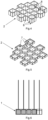
Fig. 1 - a basic cassette with detectors and extended signal-conducting cables in a perspective view, in a version with detectors in the form of cubes, -
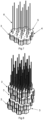
Fig. 2 - a module of four stacked cassettes, located one above the other, in a perspective view, in a version with detectors in the form of cubes, -
Fig. 3 - a module of four stacked cassettes, located one above the other, in a version with detectors in the form of cubes, in projections:- A front view
- B left-side view
- C rear view
- D right-side view
- E bottom cover in top view
- F top cover in top view
-
Fig. 4 - detector covers arranged in the base of the cassette, in a perspective view, in a version with detectors in the form of cubes, -
Fig. 5 - detector covers arranged in the cassette cover, in a perspective view, in a version with detectors in the form of cubes, -
Fig. 6 - detectors located in covers in the cassette, in cross-section, -
Fig. 7 - a basic cassette with detectors and extended signal-conducting cables in a perspective view, in a version with detectors in the form of regular prisms (honeycomb), -
Fig. 8 - a module of four stacked cassettes, located one above the other, in a perspective view, in a version with detectors in the form of regular prisms (honeycomb), -
Fig. 9 - a module of four stacked cassettes, located one above the other, in a version with detectors in the form of regular prisms (honeycomb), in projections:- A front view
- B left-side view
- C rear view
- D right-side view
- E bottom cover in top view
- F top cover in top view
-
Fig. 10 - detector covers assembled in the base of the cassette, in a perspective view, in a variant with detectors in the form of regular prisms (honeycomb), -
Fig. 11 - detector covers assembled in the cassette cover, in a perspective view, in a variant with detectors in in the form of regular prisms (honeycomb), -
Fig. 12 - detectors located in covers in the cassette, in cross-section, in a version with detectors in the form of regular prisms (honeycomb), -
Fig. 13 - basic set with detectors and signal-conducting cables in a perspective view, in a version with detectors in the form of a rhombic dodecahedron, -
Fig. 14 - a module of four sets, located one above the other, in a perspective view, in a version with detectors in the form of a rhombic dodecahedron, -
Fig. 15 - a module of four stacked cassettes, located one above the other, in a version with detectors in the form of a rhombic dodecahedron, in projections:- A front view
- B left-side view
- C rear view
- D right-side view
- E module in bottom view
- F module in top view
- The basic element of the device is an
individual detector 1 in the form of a regular solid shape, preferably in the form of a cube, individually shielded around all faces by shielding 2. Thedetectors 1 are arranged next to each other in thebasic cassettes 3 of the shielding 2, in the discussed embodiment in two layers located one above the other, shifted by a constant step and closed with alower cover 4 and anupper cover 5 of theshielding 2.Covers cassettes 3 ensure the mechanical rigidity of the structure. - The module of
cassettes 3 withdetectors 1 in layers is arranged in the active volume in a regular geometric arrangement, fitting the active volume of the phantom device as closely as possible. The optimal shape of the phantom device is a sphere. - A preferred arrangement is 64 individual detectors in 4 cassettes of 16 detectors each, in four layers one above the other.
-
Detectors 1 in the discussed version are scintillators connected via optical fibers and individual photomultipliers to the signal reading, recording and processing module, not shown in the drawing. - Each of the
individual detectors 1 has an independent, individual, straight signal-conductingcable 6. Thecable 6 is located in the symmetry axis of thedetector 1 along a straight line, not intersecting the volumes ofother detectors 1. Shifting thecassettes 3 in the assembled module by a step allows the signal-conductingcables 6 to be moved apart and routed straight-through, without bending and without collisions between thedetectors 1 of different layers of thecassettes 3. Straight-line termination and subsequent location without bending, in the case of the signal-conductingcable 6 in the form of an optical fiber, enable proper straight light-guidance, while in the case ofsuch cable 6 being in the form of an electric cable, it minimizes the time delay for the signals from individual detectors to reach the readout and control module. - The
covers 5 are equipped with throughholes 7 for the signal-conductingcables 6 of thedetectors 1 located in the layer of thecassette 3. - The shielding 2 of
detectors 1 is equipped in its walls withchannels 8 for signal-conductingcables 6 of other detectors located in adjacent layers; in the discussed embodiment with four layers - in the layers below. Thechannels 8 are located in the walls of the shielding 2, on their common or outer edges. This allows allindividual cables 6 of eachindividual detector 1 to be run independently straightly and in parallel. -
Cassettes 3 have an outline defining a puzzle-type fin connector. This shape of thecassette 3, containing one layer of sixteendetectors 1, enables further expansion of the device's volume by coherently connecting subsequent modules with cassettes in the active volume of the phantom device, making the device reconfigurable in terms of hardware. - The second way to reconfigure the device is to programmatically select only
specific detectors 1 corresponding to their appropriate voxels. Eachdetector 1 corresponding to a voxel includes an individual scintillator, optical fiber output and a signal readout system. This makes it possible to assess the dose distribution in a given area and in a given time interval - in the case of analyzing a dynamic procedure (e.g. DCAT or IMAT). - A reconfigurable device whose active area is determined in this way makes it possible to adjust and map the spatial distribution of the dose of ionizing radiation planned to be administered - to the treated volume of the body of an oncology patient undergoing radiotherapy treatment by external beams.
- In another embodiment, the regular geometric solid has the form of a regular prism with a regular hexagonal base ("honeycomb"). Due to its shape as a figure closest to a circle, a regular hexagon ensures optimal filling of the active volume of a single layer of the device, taking into account the thickness of the shielding walls of individual detectors.
- In another version, it is also possible to shape the basic element in the form of a rhombic dodecahedron as a shape closest to a sphere, ensuring optimal filling of the active volume, taking into account the thickness of the shielding walls of individual detectors. In this case, the space filling is significantly optimized (there are shifts of ½ of the height of each solid in each of the three axes), although it is possible to run straight optical fibers for two layers only, directly adjacent to each other. Rhombic dodecahedral detectors do not require covers.
Claims (11)
- A phantom device for teleradiotherapy to determine the difference between the spatial distribution of the delivered dose of ionizing radiation and the distribution of the planned dose over the active volume of the phantom device, containing several individual measurement points corresponding to voxels of the active volume over which the dose distribution is assessed, equipped with individual repeatable ionizing radiation detectors, from each of which signal-conducting cables are led to a module which reads, records and processes the signal,
characterized in thati. individual ionizing radiation detectors (1) corresponding to the voxels of the active volume have the form of a sequence of identical regular solids, individually shielded over all faces by shielding (2) and arranged to contact each other, placed within basic cassettes (3), whereby at least two layers of cassettes (3) are located one above the other and are shifted by a regular step, spatially arranged in a repetitive regular geometric manner, fitting the active measuring volume of the phantom device as closely as possible,ii. each individual detector (1) is connected to an independent, individual signal-conducting cable (6) located along a symmetry axis of this detector, continuing as a straight line and not colliding with other detectors,iii. the shielding (2) of individual detectors (1) is equipped in its walls with through channels (8) for signal-conducting cables (6) of other detectors located in adjacent layers. - The device according to claim 1, characterized in that the individual detectors (1) are in the form of cubes.
- The device according to claim 1, characterized in that the individual detectors (1) have the form of regular prisms with a regular hexagonal base, constituting a honeycomb system.
- The device according to claim 1, characterized in that the individual detectors (1) are in the form of rhombic dodecahedra.
- The device according to claim 1, characterized in that it contains 64 individual detectors (1) in 4 layer modules, 16 in each, shifted by a fixed step.
- The device according to claim 1, characterized in that the cassettes (3) are closed with a lower cover (4) and an upper cover (5) of the shielding (2).
- The device according to claim 1, characterized in that the cassettes (3) have an outline defining a puzzle-type fin joint.
- The device according to claim 7, characterized in that the layered cassette (3) modules are connected to subsequent cassette modules (3) within the active volume of the phantom device.
- The device according to claim 1, characterized in that the individual ionizing radiation detectors (1) are scintillators, the shielding (2) is light-tight, and the signal-conducting cables (6) are optical fibers.
- The device according to claim 5, characterized in that the dose detectors (1) in the form of scintillators are coupled to individual photomultipliers.
- The device according to claim 1, characterized in that the signal-conducting cables (6) led from the individual ionizing radiation detectors (1) are optical fibers or electric cables.
Applications Claiming Priority (1)
| Application Number | Priority Date | Filing Date | Title |
|---|---|---|---|
| PL446944A PL446944A1 (en) | 2023-11-30 | 2023-11-30 | Phantom device for teleradiotherapy for determining the spatial distribution of ionizing radiation dose |
Publications (1)
| Publication Number | Publication Date |
|---|---|
| EP4563193A1 true EP4563193A1 (en) | 2025-06-04 |
Family
ID=89474257
Family Applications (1)
| Application Number | Title | Priority Date | Filing Date |
|---|---|---|---|
| EP23220413.1A Pending EP4563193A1 (en) | 2023-11-30 | 2023-12-27 | Phantom device for teleradiotherapy to determine the spatial distribution of dose of ionizing radiation |
Country Status (2)
| Country | Link |
|---|---|
| EP (1) | EP4563193A1 (en) |
| PL (1) | PL446944A1 (en) |
Citations (6)
| Publication number | Priority date | Publication date | Assignee | Title |
|---|---|---|---|---|
| US20090236510A1 (en) * | 2007-11-21 | 2009-09-24 | Universite Laval | Scintillating fiber dosimeter array |
| US20120292517A1 (en) | 2011-05-19 | 2012-11-22 | Washington University | Real-time imaging dosimeter systems and method |
| US20130006035A1 (en) * | 2011-06-22 | 2013-01-03 | The Christie NHS Foundation Trust | Radiotherapy phantom |
| US20140217295A1 (en) | 2011-04-01 | 2014-08-07 | Luc Beaulieu | Planar and volumetric dosimeter with scintillating material for radiotherapy treatment using tomographic reconstruction |
| US20210311212A1 (en) | 2018-07-23 | 2021-10-07 | Ion Beam Applications S.A. | Scintillating detectors for quality assurance of a therapy photon beam |
| US20220326402A1 (en) | 2015-09-14 | 2022-10-13 | Reflexion Medical, Inc. | High resolution dynamic detector for imaging and dosimetry in megavoltage radiation therapy |
Family Cites Families (5)
| Publication number | Priority date | Publication date | Assignee | Title |
|---|---|---|---|---|
| US3310885A (en) * | 1964-06-04 | 1967-03-28 | Samuel W Alderson | Radio-therapy phantom |
| KR100513692B1 (en) * | 2003-05-09 | 2005-09-13 | 정광호 | Heterogeneous phantom for radiation dosimetry |
| KR101777499B1 (en) * | 2016-02-16 | 2017-09-11 | 서울대학교병원 | Phantoms for Quality Assurance of Magnetic Resonance Image Guided Radiation Therapy Machine |
| KR102568345B1 (en) * | 2020-11-10 | 2023-08-22 | 연세대학교 산학협력단 | Radiotherapy equipment quality assurance device, phantom for measurement of quality assurance and scintillator structure thereof |
| EP4186562B1 (en) * | 2021-11-26 | 2023-11-29 | Vilnius University | System and method for brachytherapy procedure planning and verification |
-
2023
- 2023-11-30 PL PL446944A patent/PL446944A1/en unknown
- 2023-12-27 EP EP23220413.1A patent/EP4563193A1/en active Pending
Patent Citations (6)
| Publication number | Priority date | Publication date | Assignee | Title |
|---|---|---|---|---|
| US20090236510A1 (en) * | 2007-11-21 | 2009-09-24 | Universite Laval | Scintillating fiber dosimeter array |
| US20140217295A1 (en) | 2011-04-01 | 2014-08-07 | Luc Beaulieu | Planar and volumetric dosimeter with scintillating material for radiotherapy treatment using tomographic reconstruction |
| US20120292517A1 (en) | 2011-05-19 | 2012-11-22 | Washington University | Real-time imaging dosimeter systems and method |
| US20130006035A1 (en) * | 2011-06-22 | 2013-01-03 | The Christie NHS Foundation Trust | Radiotherapy phantom |
| US20220326402A1 (en) | 2015-09-14 | 2022-10-13 | Reflexion Medical, Inc. | High resolution dynamic detector for imaging and dosimetry in megavoltage radiation therapy |
| US20210311212A1 (en) | 2018-07-23 | 2021-10-07 | Ion Beam Applications S.A. | Scintillating detectors for quality assurance of a therapy photon beam |
Non-Patent Citations (1)
| Title |
|---|
| LACROIX FRÃ DERIC ET AL: "Clinical prototype of a plastic water-equivalent scintillating fiber dosimeter array for QA applications", MEDICAL PHYSICS, AIP, MELVILLE, NY, US, vol. 35, no. 8, 17 July 2008 (2008-07-17), pages 3682 - 3690, XP012116197, ISSN: 0094-2405, DOI: 10.1118/1.2953564 * |
Also Published As
| Publication number | Publication date |
|---|---|
| PL446944A1 (en) | 2025-06-02 |
Similar Documents
| Publication | Publication Date | Title |
|---|---|---|
| US7521681B2 (en) | Non-rotating transaxial radionuclide imaging | |
| US4095107A (en) | Transaxial radionuclide emission camera apparatus and method | |
| AU690313B2 (en) | X-ray phantom apparatus | |
| EP3298434B1 (en) | A proton imaging system for optimization of proton therapy | |
| US4342916A (en) | Method of and apparatus for tomographic examination of structures by X-ray or gamma ray scanning | |
| KR20120016195A (en) | Interweave Multi-opening Collimator for Three-Dimensional Radiation Imaging Applications | |
| US10989819B2 (en) | Gamma radiation detector with parallax compensation | |
| US20160103227A1 (en) | Large-volume scintillator detector for rapid real-time 3-d dose imaging of advanced radiation therapy modalities | |
| US7491941B2 (en) | Scanning focal point apparatus | |
| US11783519B2 (en) | Collimators for medical imaging systems and image reconstruction methods thereof | |
| KR101948800B1 (en) | 3d scattering radiation imager, radiation medical apparatus having the same and method for placing the 3d scattering radiation imager | |
| IL294681A (en) | Medical imaging systems based on a receiver (collimator) and a detector | |
| US3777148A (en) | Collimator | |
| EP4186562B1 (en) | System and method for brachytherapy procedure planning and verification | |
| US7402813B2 (en) | Lens system for nuclear medicine gamma ray camera | |
| JP7125109B2 (en) | Data analysis device, comparison display device, treatment plan data editing device, dose distribution measuring method, program and dose distribution measuring device | |
| EP1996960A2 (en) | Nuclear medicine imaging system with high efficiency transmission measurement | |
| CN118576234B (en) | Parallel hole collimator for small animal SPECT system and imaging method | |
| KR101749324B1 (en) | 3d scattering radiation imager and radiation medical apparatus | |
| McElroy et al. | Evaluation of A-SPECT: a desktop pinhole SPECT system for small animal imaging | |
| Archambault et al. | Basic quality assurance: profiles and depth dose curves | |
| US3659103A (en) | Radiation scanning device for detecting a plurality of different radiating sources positioned in different planes | |
| Patton | Tomography | |
| WO2025172355A1 (en) | Biopsy system and method | |
| CN116917773A (en) | Radiation detection systems and methods |
Legal Events
| Date | Code | Title | Description |
|---|---|---|---|
| PUAI | Public reference made under article 153(3) epc to a published international application that has entered the european phase |
Free format text: ORIGINAL CODE: 0009012 |
|
| STAA | Information on the status of an ep patent application or granted ep patent |
Free format text: STATUS: THE APPLICATION HAS BEEN PUBLISHED |
|
| AK | Designated contracting states |
Kind code of ref document: A1 Designated state(s): AL AT BE BG CH CY CZ DE DK EE ES FI FR GB GR HR HU IE IS IT LI LT LU LV MC ME MK MT NL NO PL PT RO RS SE SI SK SM TR |
|
| STAA | Information on the status of an ep patent application or granted ep patent |
Free format text: STATUS: REQUEST FOR EXAMINATION WAS MADE |
|
| 17P | Request for examination filed |
Effective date: 20251126 |
|
| GRAP | Despatch of communication of intention to grant a patent |
Free format text: ORIGINAL CODE: EPIDOSNIGR1 |
|
| STAA | Information on the status of an ep patent application or granted ep patent |
Free format text: STATUS: GRANT OF PATENT IS INTENDED |
|
| INTG | Intention to grant announced |
Effective date: 20260402 |