EP4563137A2 - Closure device - Google Patents
Closure device Download PDFInfo
- Publication number
- EP4563137A2 EP4563137A2 EP25171209.7A EP25171209A EP4563137A2 EP 4563137 A2 EP4563137 A2 EP 4563137A2 EP 25171209 A EP25171209 A EP 25171209A EP 4563137 A2 EP4563137 A2 EP 4563137A2
- Authority
- EP
- European Patent Office
- Prior art keywords
- ring
- stopper
- closure device
- neck
- locking tabs
- Prior art date
- Legal status (The legal status is an assumption and is not a legal conclusion. Google has not performed a legal analysis and makes no representation as to the accuracy of the status listed.)
- Pending
Links
Images




Classifications
-
- B—PERFORMING OPERATIONS; TRANSPORTING
- B65—CONVEYING; PACKING; STORING; HANDLING THIN OR FILAMENTARY MATERIAL
- B65D—CONTAINERS FOR STORAGE OR TRANSPORT OF ARTICLES OR MATERIALS, e.g. BAGS, BARRELS, BOTTLES, BOXES, CANS, CARTONS, CRATES, DRUMS, JARS, TANKS, HOPPERS, FORWARDING CONTAINERS; ACCESSORIES, CLOSURES, OR FITTINGS THEREFOR; PACKAGING ELEMENTS; PACKAGES
- B65D51/00—Closures not otherwise provided for
- B65D51/002—Closures to be pierced by an extracting-device for the contents and fixed on the container by separate retaining means
-
- A—HUMAN NECESSITIES
- A61—MEDICAL OR VETERINARY SCIENCE; HYGIENE
- A61J—CONTAINERS SPECIALLY ADAPTED FOR MEDICAL OR PHARMACEUTICAL PURPOSES; DEVICES OR METHODS SPECIALLY ADAPTED FOR BRINGING PHARMACEUTICAL PRODUCTS INTO PARTICULAR PHYSICAL OR ADMINISTERING FORMS; DEVICES FOR ADMINISTERING FOOD OR MEDICINES ORALLY; BABY COMFORTERS; DEVICES FOR RECEIVING SPITTLE
- A61J1/00—Containers specially adapted for medical or pharmaceutical purposes
- A61J1/14—Details; Accessories therefor
- A61J1/1412—Containers with closing means, e.g. caps
- A61J1/1425—Snap-fit type
-
- B—PERFORMING OPERATIONS; TRANSPORTING
- B65—CONVEYING; PACKING; STORING; HANDLING THIN OR FILAMENTARY MATERIAL
- B65B—MACHINES, APPARATUS OR DEVICES FOR, OR METHODS OF, PACKAGING ARTICLES OR MATERIALS; UNPACKING
- B65B7/00—Closing containers or receptacles after filling
- B65B7/16—Closing semi-rigid or rigid containers or receptacles not deformed by, or not taking-up shape of, contents, e.g. boxes or cartons
- B65B7/28—Closing semi-rigid or rigid containers or receptacles not deformed by, or not taking-up shape of, contents, e.g. boxes or cartons by applying separate preformed closures, e.g. lids, covers
- B65B7/2842—Securing closures on containers
-
- B—PERFORMING OPERATIONS; TRANSPORTING
- B65—CONVEYING; PACKING; STORING; HANDLING THIN OR FILAMENTARY MATERIAL
- B65D—CONTAINERS FOR STORAGE OR TRANSPORT OF ARTICLES OR MATERIALS, e.g. BAGS, BARRELS, BOTTLES, BOXES, CANS, CARTONS, CRATES, DRUMS, JARS, TANKS, HOPPERS, FORWARDING CONTAINERS; ACCESSORIES, CLOSURES, OR FITTINGS THEREFOR; PACKAGING ELEMENTS; PACKAGES
- B65D41/00—Caps, e.g. crown caps or crown seals, i.e. members having parts arranged for engagement with the external periphery of a neck or wall defining a pouring opening or discharge aperture; Protective cap-like covers for closure members, e.g. decorative covers of metal foil or paper
- B65D41/32—Caps or cap-like covers with lines of weakness, tearing-strips, tags, or like opening or removal devices, e.g. to facilitate formation of pouring openings
- B65D41/46—Snap-on caps or cap-like covers
- B65D41/465—Snap-on caps or cap-like covers with integral internal sealing means
-
- B—PERFORMING OPERATIONS; TRANSPORTING
- B65—CONVEYING; PACKING; STORING; HANDLING THIN OR FILAMENTARY MATERIAL
- B65D—CONTAINERS FOR STORAGE OR TRANSPORT OF ARTICLES OR MATERIALS, e.g. BAGS, BARRELS, BOTTLES, BOXES, CANS, CARTONS, CRATES, DRUMS, JARS, TANKS, HOPPERS, FORWARDING CONTAINERS; ACCESSORIES, CLOSURES, OR FITTINGS THEREFOR; PACKAGING ELEMENTS; PACKAGES
- B65D45/00—Clamping or other pressure-applying devices for securing or retaining closure members
- B65D45/32—Clamping or other pressure-applying devices for securing or retaining closure members for applying radial or radial and axial pressure, e.g. contractible bands encircling closure member
- B65D45/322—Clamping or other pressure-applying devices for securing or retaining closure members for applying radial or radial and axial pressure, e.g. contractible bands encircling closure member the clamping device being an annular member moved axially to clamp the closure by using radial pressure
-
- A—HUMAN NECESSITIES
- A61—MEDICAL OR VETERINARY SCIENCE; HYGIENE
- A61J—CONTAINERS SPECIALLY ADAPTED FOR MEDICAL OR PHARMACEUTICAL PURPOSES; DEVICES OR METHODS SPECIALLY ADAPTED FOR BRINGING PHARMACEUTICAL PRODUCTS INTO PARTICULAR PHYSICAL OR ADMINISTERING FORMS; DEVICES FOR ADMINISTERING FOOD OR MEDICINES ORALLY; BABY COMFORTERS; DEVICES FOR RECEIVING SPITTLE
- A61J1/00—Containers specially adapted for medical or pharmaceutical purposes
- A61J1/14—Details; Accessories therefor
- A61J1/1406—Septums, pierceable membranes
-
- B—PERFORMING OPERATIONS; TRANSPORTING
- B65—CONVEYING; PACKING; STORING; HANDLING THIN OR FILAMENTARY MATERIAL
- B65D—CONTAINERS FOR STORAGE OR TRANSPORT OF ARTICLES OR MATERIALS, e.g. BAGS, BARRELS, BOTTLES, BOXES, CANS, CARTONS, CRATES, DRUMS, JARS, TANKS, HOPPERS, FORWARDING CONTAINERS; ACCESSORIES, CLOSURES, OR FITTINGS THEREFOR; PACKAGING ELEMENTS; PACKAGES
- B65D51/00—Closures not otherwise provided for
- B65D51/18—Arrangements of closures with protective outer cap-like covers or of two or more co-operating closures
- B65D51/20—Caps, lids, or covers co-operating with an inner closure arranged to be opened by piercing, cutting, or tearing
-
- B—PERFORMING OPERATIONS; TRANSPORTING
- B65—CONVEYING; PACKING; STORING; HANDLING THIN OR FILAMENTARY MATERIAL
- B65D—CONTAINERS FOR STORAGE OR TRANSPORT OF ARTICLES OR MATERIALS, e.g. BAGS, BARRELS, BOTTLES, BOXES, CANS, CARTONS, CRATES, DRUMS, JARS, TANKS, HOPPERS, FORWARDING CONTAINERS; ACCESSORIES, CLOSURES, OR FITTINGS THEREFOR; PACKAGING ELEMENTS; PACKAGES
- B65D51/00—Closures not otherwise provided for
- B65D51/24—Closures not otherwise provided for combined or co-operating with auxiliary devices for non-closing purposes
- B65D51/241—Closures not otherwise provided for combined or co-operating with auxiliary devices for non-closing purposes provided with freeze-drying means
Definitions
- a closure device for closing a container which in one embodiment, includes a preassembled stopper. Another embodiment relates to a container equipped with such a closure device.
- a glass or polymeric bottle can be used to store an active ingredient in freeze-dried form, in powder form, or in the form of a liquid solution. Such a bottle must be closed off in a leak-tight manner, so as to maintain its contents in a satisfactory state of preservation, until the date on which it is used.
- a closure device can be used that comprises an elastomeric stopper that has the function of sealing the opening of the container from the ingress or egress of gas, liquids, and bacteria.
- Such a device may further comprise a means for maintaining the container in a sealed condition, such as a crimped aluminum seal or plastic cap, that is designed to be held in place around the stopper so as to isolate the stopper from the outside and so as to oppose removal of the stopper.
- a means for maintaining the container in a sealed condition such as a crimped aluminum seal or plastic cap, that is designed to be held in place around the stopper so as to isolate the stopper from the outside and so as to oppose removal of the stopper.
- each container is filled with a quantity of substance for freeze-drying, and then the respective stopper is placed on or in the neck of the container in such a manner as to be secured thereto, while also preserving communication between the outside environment and the inside of the container.
- Containers filled and pre-stopped in this way are then placed in batches on the shelves of a freeze drier inside which the substances are dehydrated.
- vacuum cold-drying is performed to help ensure that the water is extracted from the substance by sublimation and evaporation.
- a closure device for sealing a container having a neck with an opening and an annular collar.
- the closure device comprises a stopper and a cap assembly.
- the cap assembly is configured to surround both the stopper and the neck in a sealed condition.
- the cap assembly comprises a ring and a crown.
- the ring contains the stopper and comprises a plurality of locking tabs.
- the crown comprises a skirt telescopically mounted over the ring and configured to radially deflect the plurality of locking tabs inwardly under the annular collar when the crown is axially displaced towards the neck of the container.
- a first locking tab of the plurality of locking tabs has a first axial height and a second locking tab of the plurality of locking tabs has a second axial height, wherein the first axial height is less than the second axial height.
- a closure device for sealing a container having a neck with an opening and an annular collar.
- the closure device comprises a stopper having a flange and a cap assembly.
- the cap assembly is configured to surround both the stopper and the neck in a sealed condition and comprises a ring and a crown.
- the ring contains the stopper and includes a plurality of locking tabs.
- the crown comprises a skirt telescopically mounted over the and is configured to radially deflect the plurality of locking tabs inwardly under the annular collar.
- the ring also comprises an inner circumferential surface including a plurality of raised steps extending inwardly radially from the inner circumferential surface to a diameter that is less than or equal to the diameter of the stopper flange.
- the closure devices comprise a stopper and sealing means provided in the form of a cap assembly.
- the stopper is loaded within the cap assembly, and the closure device may be applied to the opening of a container, such as a vial, to capture an annular collar around the neck of the container and maintain the stopper in a sealed condition.
- the closure devices according to the various embodiments disclosed herein may be used in typical filling and lyophilization processes, such as those described in U.S. Patent No. 8,714,384 , the content of which is incorporated by reference herein in its entirety.
- the bottles 1 may alternatively be made of a ceramic or a polymeric material, such as polyethylene (PE), polyethylene terephthalate (PET), glycol-modified polyethylene terephthalate (PETG), high density polyethylene (PEHD) and the like.
- bottle 1 is in the process of being filled with product P, for example, a medication.
- Pipette 2 is introduced into bottle 1 through its mouth 11 which is defined by a neck 12 presenting an outer collar 13.
- X1 shows the symmetrical axis of bottle 1.
- the device 50 comprises an elastomeric stopper 51 adapted to be partially introduced into the mouth 11, while remaining on the side 131 of the collar 13 opposite the bottom 14 of the bottle 1.
- a filling line may include a plurality of pipettes in order to simultaneously fill multiple containers.
- an automated filling line may also be capable of simultaneously applying a plurality of stoppers and cap assemblies to the container after the containers are filled with product.
- the device 50 also comprises a cap 52 aimed at covering and maintaining the stopper 51 and the neck 12 in a closed configuration.
- the stopper 51 is preferably pre-loaded into the cap 52 and held in an axial position prior to affixing the cap onto the neck 12 of the bottle 1, described in greater detail below.
- the stopper 51 is preferably provided with a vent 512 which communicates with the atmosphere on the exterior of the container 1.
- a plurality of filled containers 1 having a closure device 50 applied thereon may then be loaded into a lyophiliser 300, as illustrated in FIGS. 3 to 5 as one lot of bottles 1. In FIGS.
- three bottles represent one lot which can comprise several hundred, or even several million, bottles used in the lyophiliser 300.
- the bottles may be loaded into a lyophiliser on several stacked shelves. After loading the containers 1 into the lyophiliser, the internal temperature and pressure within the lyophiliser is reduced until the water present in each bottle 1 is vaporized and exits the container through the vents 512 in the stoppers 51 and the space between cap 52 and the collar 13, as represented by the arrows F1 in FIG. 3 .
- a press 301 may apply a force E2 over all of the closure devices 50 inside the lyophiliser, as represented in FIGS. 4 and 5 .
- the force E2 is evenly applied on the devices 50 parallel to the longitudinal axis X1 of the bottles 1 and the necks 12.
- This axial force E2 exerted by the press 301 inside the lyophiliser may be pneumatically controlled or by a mechanical jack 302, for example.
- the force E2 applied by the press 301 causes axial displacement of the closure devices 50 towards their respective containers 1.
- the elastomeric stoppers 51 are first inserted to a depth within the openings 11 in each container 1, such that the vents 512 are no longer exposed and the contents P of the containers 1 are isolated from the exterior of the containers 1, and second, further depression of the closure devices 50 by the press 301 causes the caps 52 to capture the respective necks 12 of each container 1, thereby compressing and sealing the stoppers 51 against the top sides 131 of the necks 12 of the containers 1.
- the closure device 50 comprises an elastomeric stopper 51, a ring portion 53, a crown portion 54, and a lid 56.
- the lid 56 is attached to the crown portion 54 and is preferably configured to be easily removed by one hand of the user, for example.
- the closure device 50, and more particularly each component of the closure device 50 as described in detail herein, is preferably made of a plastic material, and more preferably a thermoplastic material such as, but not limited to, PE, PET, PETG, PEHD, polypropylene (PP) or acrylonitrile butadiene styrene (ABS). More preferably, the closure device 50 is made of a pharma grade polypropylene material, and more particularly a pharma grade polypropylene material that is free of contaminants or critical substances (e.g., bisphenol A or formaldehyde).
- the lid 56 comprises a top portion that may optionally include a plurality of notches 561 around the perimeter of the top surface of the top portion.
- the notches 561 may facilitate the centering and application of force by an automated manufacturing line to attach the lid 56 to the crown 54.
- a lid skirt 562 may downwardly extend from the top portion of the lid 56, and a plurality of axially extending cuts 563 may be provided in the lid skirt 562 to more easily deform and separate the lid 56 from the crown 54 when a user intends to access the stopper 51.
- the lid 56 may further comprise a plurality of deformable tabs 564 that extend axially from the underside of the top portion of the lid 56 for attaching the lid 56 to the crown 54.
- the crown 54 includes a top portion having a centrally located aperture 541, as well as a crown skirt 542 downwardly extending from the top portion and is intended to constitute the external peripheral envelope of the closure device 50.
- the circumferential wall of the crown skirt 542 includes a plurality of radially inwardly protruding arcuate ledges 543 for providing a surface that may be captured by the ring portion 53 in the sealed condition, described in greater detail below.
- each ledge 543 is an opening 544.
- the ledges 543 and openings 544 are preferably equidistantly spaced about a common circumference of the skirt 542.
- FIG. 9 the lid 56 and crown 54 are illustrated in the assembled condition.
- the plurality of tabs 564 are inserted through the aperture 541 of the crown 54 and the tabs 564 are deformed in order to provide each of the tabs 564 with a lip 565 that captures the underside of the top portion of the crown 54.
- the ring portion 53 similar to the crown portion 54, includes a top portion having a centrally located aperture 530 and a skirt portion 532 downwardly extending from the top portion.
- the ring portion 53 includes a circular interior section whose internal diameter is sufficient to allow it to surround the collar 13 of the vial 1.
- the top portion is further provided with a collar 531 configured to catch the ledges 543 of the crown 54 when the closure device 50 is in the sealed condition, described in greater detail below.
- a bottom portion 533 of the ring 53 located on an opposing end of the ring 53 relative to the top portion includes a plurality of axially extending resilient locking tabs 534, wherein the distal end of the locking tabs 534 (i.e.
- the end of the locking tabs 534 closest to the bottom portion 533) are preferably hingedly attached to the bottom portion 533.
- Each of the locking tabs 534 are located within a window 535 in the circumferential wall of the ring skirt 532.
- the ring 53 preferably comprises two pairs of locking tabs 534a and 534b, wherein the locking tabs 534a of the first pair being located in opposing relation to each other about the circumference of the ring skirt 532 and the locking tabs 534b of the second pair being located in opposing relation to each other about the circumference of the ring skirt 532.
- the locking tabs 534a of the first pair have an axial height X and a circumferential width A
- the locking tabs 534b of the second pair have an axial height Y and a circumferential width B, wherein the axial height X is less than the axial height Y and the circumferential width A is less than the circumferential width B.
- the circumferential wall of the ring skirt 532 is also provided with plurality of circumferential ribs 520 and a plurality of apertures 536 located at an axial height between the collar 531 and the locking tabs 534.
- Each of the apertures 536 includes an inwardly radially extending retaining arm 537 attached to the lower edge of the aperture 536.
- the ring 53 may further comprise a circular protuberance 538 on the bottom surface of the top portion around the centrally located aperture 530.
- the protuberance 538 ensures that an evenly distributed force is applied to the top surface of the stopper 51, when the closure device is in a sealed condition.
- the circular protuberance 538 is in the form of a continuous circle.
- the circular protuberance may comprise a plurality of segments 538a, 538b, 538c, 538d, 538e. The segments are preferably of equal size and spaced evenly to ensure the aforementioned evenly distributed force when the closure device in the sealed condition. Increasing the space between each of the plurality of segments also reduces the force necessary to compact the closure device and achieve the sealed condition.
- the stopper 51 Prior to affixing the closure device 50 to a container, the stopper 51 is preloaded into the ring portion 53.
- the previously mentioned retaining arms 537 extend inwardly to a diameter that is less than the diameter of the flange 510 of the stopper 51, thereby, retaining the stopper 51 within upper inner chamber of the ring portion 53.
- the inner circumferential surface of the skirt 532 adjacent to the top portion of the ring 53 is provided with a plurality of raised steps 539.
- the raised steps 539 extends inwardly radially to a diameter that is less than or equal to the diameter of the stopper flange 510 in order to provide an interference fit between the stopper 51 and the inner chamber of the ring 53. However, it is preferred that the raised steps 539 are only present along a portion of the inner circumference of the upper chamber adjacent the top portion of the ring 53 in order to minimize the force necessary to compress the stopper flange 510 and lock the closure device 50 in the sealed condition.
- the raised steps 539 are present, with increasing preference in the order presented, about 50% or less, 45% or less, 40% or less, 35% or less, 30% or less, 25% or less, 20% or less, 15% or less, 10% or less, or 5% or less of the inner circumference of the ring skirt 532.
- the crown 54 After affixing the lid 56 to the crown 54 and loading the stopper 51 into the ring 53, the crown 54 is then telescopically mounted over the ring 53 the plurality of circumferential ribs 520 of the ring 53 mates with an inner circumferential groove 545 of the crown 54, thereby providing the closure device 50 in an assembled condition, as best viewed in FIG. 11 .
- the geometry of ring 53, crown 54 and lid 56 is chosen in such a way that the maximum exterior diameter of the crown 54 has a value less than 13.5 mm, more preferably between 12.8 and 13.2 mm, and most preferably less than or equal to 12.8 mm.
- the closure device 50 mounted onto the vial 1 does not exceed or slightly exceeds the diameter of the vial 1. This reduces the likelihood that the bottles will be imbalanced and easily tip over when the closure device 50 is applied or during lyophilization.
- FIGS. 12A to 12F A method of sealing a vial using a closure device according to another embodiment disclosed herein will be described with reference to FIGS. 12A to 12F .
- a crown 54 is in a holding configuration in which external ribs 535 of a ring 53 remain inserted in an inner peripheral groove 5461 of the crown 54. In this configuration, the crown 54 does not interact with locking tabs 537 of the ring 53.
- Applying a force E2 has the effect of making the crown 54 move in the direction of the bottom 14 of each of the vials 1, as represented by the passage from the configuration in FIGS. 3 and 12A to that of FIGS. 4 and 12B .
- the E2 force is transmitted from the crown 54 to the ring 53 because of the interference fit between the peripheral groove 5461 and the external ribs 535 which cooperate.
- external ribs 535 and the peripheral mouth 5461 constitute the force transmission means E2 from the crown 54 to the ring 53.
- the force E2 exerted on each device 50 has the effect of sliding the tabs 537 of the ring 53 along the outer surface of the vial collar 13, and ultimately under the vial collar 13.
- the retaining arms 537 also impinge and slide along the outer surface of the vial 13, thereby causing the retaining arms 537 to deflect radially outwards and into their respective apertures 536, such that the retaining arms 537 no longer contact or interfere with the bottom surface of the stopper flange 510 and allow the stopper to be inserted into the opening of the vial 1.
- the top section of the ring 53 contacts with the upper surface 511 of the stopper 51 which halts the progression of the ring 53 in the direction of the base 14.
- the continued application of the force E2 on the crown 54 of each device 50 has the effect of driving the external rib 535 of the ring out of the peripheral groove 5461 by elastic deformation of the skirt 533, which allows the crown 54 to successively attain the position of FIGS. 12E and 12F .
- This movement also has the effect of causing ledges 5431 below the openings 543 in the crown 54 to catch the undersurface 5313 of the annular collar 5311 of the ring 53.
- D531 shows the maximum diameter of the annular collar 5311.
- D543 shows the minimum diameter shared by the radially innermost points of each of the ledges 5431 towards an axis X52.
- the zones 5443 below the arcuate ledges 5431 are elastically deformed by sliding against the surface 5314 of the ring collar 5311, while passing from the configuration of FIG. 12D to the configuration of FIGS. 12E and 12F .
- zones 5443 cause the zones 5443 to revert to their original shape after the ledges 5431 are below the annular collar 5311, such that the annular collar 5311 provides a catch or stop preventing any separation between the crown 54 and the ring 53 that may occur from vertical axial displacement of the crown 54 relative to the ring 53. Therefore, if a withdrawal force E3 of the crown 54 is exerted on the closure device, as represented in FIG. 12F , both the ledges 5431 will be impeded by the annular collar 5311 and the locking 537 will be impeded by the vial collar 13.
Landscapes
- Engineering & Computer Science (AREA)
- Mechanical Engineering (AREA)
- Health & Medical Sciences (AREA)
- Pharmacology & Pharmacy (AREA)
- Life Sciences & Earth Sciences (AREA)
- Animal Behavior & Ethology (AREA)
- General Health & Medical Sciences (AREA)
- Public Health (AREA)
- Veterinary Medicine (AREA)
- Closures For Containers (AREA)
- Medical Preparation Storing Or Oral Administration Devices (AREA)
Abstract
Description
- This application claims the benefit of and priority to
U.S. Provisional Application No. 63/049,154, titled "CLOSURE DEVICE", filed on July 8, 2020 - A closure device for closing a container is provided, which in one embodiment, includes a preassembled stopper. Another embodiment relates to a container equipped with such a closure device.
- In the field of containers for medication, a glass or polymeric bottle can be used to store an active ingredient in freeze-dried form, in powder form, or in the form of a liquid solution. Such a bottle must be closed off in a leak-tight manner, so as to maintain its contents in a satisfactory state of preservation, until the date on which it is used. In order to close a bottle hermetically, a closure device can be used that comprises an elastomeric stopper that has the function of sealing the opening of the container from the ingress or egress of gas, liquids, and bacteria. Such a device may further comprise a means for maintaining the container in a sealed condition, such as a crimped aluminum seal or plastic cap, that is designed to be held in place around the stopper so as to isolate the stopper from the outside and so as to oppose removal of the stopper.
- When using such a closure device for freeze-dried pharmaceutical substances, for example, each container is filled with a quantity of substance for freeze-drying, and then the respective stopper is placed on or in the neck of the container in such a manner as to be secured thereto, while also preserving communication between the outside environment and the inside of the container. Containers filled and pre-stopped in this way are then placed in batches on the shelves of a freeze drier inside which the substances are dehydrated. During freeze-drying of the contents of a container, vacuum cold-drying is performed to help ensure that the water is extracted from the substance by sublimation and evaporation.
- Once the substances have been dehydrated within the freeze drier, pressure is applied to all of the stoppers of the containers in such a manner so as to help ensure that the containers are stopped hermetically by each stopper being engaged on or within the opening of the neck of the corresponding container. Such stopping in batches is generally performed with the elastomeric stopper alone, without the sealing means. After removing the containers from the freeze drier, additional processing is performed to position the seal in place on each container. However, it is desirable to avoid such an additional operation. Thus, it has been envisaged to place the corresponding sealing means on each of the stoppers of the pre-stopped containers before freeze drying them, so that the sealing means may be applied substantially simultaneously while the stoppers are being pressed into place inside the freeze drier.
- When the sealing means are applied, so as to be affixed around the neck of the corresponding container, friction creates resistance to this movement, the magnitude of which varies as a function firstly of the manufacturing tolerances of the component parts of the seal, and secondly of the pre-positioning of the parts when they are installed on the neck of the container. Thus, when a presser plate is used inside the freeze drier to lock the seals on a large number of corresponding containers, certain seals may not lock correctly in view of the manufacturing tolerances of the component parts of the seals and in view of the operating clearances of the presser plate. Also, the dimensional variations in the containers themselves and in the stoppers that are used further complicate the closure of a batch of containers.
- Therefore, there is a need for improved closure devices which provide for secure and stable positioning of a sealing means on a vial stopper.
- In one aspect, a closure device is provided for sealing a container having a neck with an opening and an annular collar. The closure device comprises a stopper and a cap assembly. The cap assembly is configured to surround both the stopper and the neck in a sealed condition. The cap assembly comprises a ring and a crown. The ring contains the stopper and comprises a plurality of locking tabs. The crown comprises a skirt telescopically mounted over the ring and configured to radially deflect the plurality of locking tabs inwardly under the annular collar when the crown is axially displaced towards the neck of the container. A first locking tab of the plurality of locking tabs has a first axial height and a second locking tab of the plurality of locking tabs has a second axial height, wherein the first axial height is less than the second axial height.
- In another aspect, a closure device is provided for sealing a container having a neck with an opening and an annular collar. The closure device comprises a stopper having a flange and a cap assembly. The cap assembly is configured to surround both the stopper and the neck in a sealed condition and comprises a ring and a crown. The ring contains the stopper and includes a plurality of locking tabs. The crown comprises a skirt telescopically mounted over the and is configured to radially deflect the plurality of locking tabs inwardly under the annular collar. The ring also comprises an inner circumferential surface including a plurality of raised steps extending inwardly radially from the inner circumferential surface to a diameter that is less than or equal to the diameter of the stopper flange.
- These and other aspects of the various embodiments disclosed herein will be apparent in view of the following description.
- Various aspects and embodiments of the application will be described with reference to the following figures. It should be appreciated that the figures are not necessarily drawn to scale. The figures depict one or more implementations in accord with the present concepts, by way of example only, not by way of limitations. In the figures, like reference numerals may refer to the same or similar elements.
-
FIGS. 1 to 5 are axial cross-sectional and a sectional perspective schematic views of the several stages of filling, drying, and sealing a product in containers sealed with a closure device according to the disclosure; -
FIG. 6A is a top perspective view of a closure device according to an embodiment disclosed herein; -
FIG. 6B is an exploded view of the closure device ofFIG. 6A ; -
FIG. 7A is a top perspective view of a removable lid included in the closure device disclosed herein; -
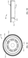
FIG. 7B is a top plan view of the removable lid ofFIG. 7A ; -
FIG. 7C is a bottom plan view of the removable lid ofFIG. 7A ; -
FIG. 7D is a front view of the removable lid ofFIG. 7A ; -
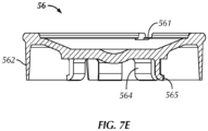
FIG. 7E is a cross-sectional front view of the removable lid ofFIG. 7A ; -
FIG. 8A is a top perspective view of a crown included in the closure device disclosed herein; -
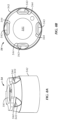
FIG. 8B is a top plan view of the crown ofFIG. 8A ; -
FIG. 8C is a bottom plan view of the crown ofFIG. 8A ; -
FIG. 8D is a front view of the crown ofFIG. 8A ; -
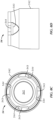
FIG. 8E is a cross-sectional side view of the crown ofFIG. 8A ; -
FIG 9 is a cross-sectional front view of the combination of the lid and crown in the closure device disclosed herein; -
FIG. 10A is a top perspective view of a ring included in the closure device disclosed herein; -
FIG. 10B is a top plan view of the ring ofFIG. 10A ; -
FIG. 10C is a bottom plan view of the ring ofFIG. 10A ; -
FIG. 10D is a front view of the ring ofFIG. 10A ; -
FIG. 10E is a bottom perspective view of the ring ofFIG. 10A ; -
FIGS. 10F and 10G are cross-sectional front and side views, respectively, of the ring ofFIG. 10A ; -
FIG. 10H is a bottom plan view of another embodiment of a ring; -
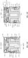
FIG. 11 is a cross-sectional front view of the closure device ofFIGS. 6A and6B ; -
FIG. 12A is a large scale view of the detail VI inFIG. 3 ; -
FIG. 12B is a large scale view of the detail X inFIG. 4 , -
FIG. 12C is a cross-section according to the line XI-XI inFIG. 12B , -
FIG. 12D is a cross-section similar toFIG. 12C during an intermediary stage between the configurations ofFIGS. 4 and5 , -
FIG. 12E is larger scale view of the detail XIII ofFIG. 5 and -
FIG. 12F is a cross section according to the line XIV-XIII ofFIG. 12E . - Certain terminology is used in the following description for convenience only and is not limiting. The words "lower," "bottom," "upper" and "top" designate directions in the drawings to which reference is made. The words "inwardly," "outwardly," "upwardly" and "downwardly" refer to directions toward and away from, respectively, the geometric center of the liquid transfer device, and designated parts thereof, in accordance with the present disclosure. Unless specifically set forth herein, the terms "a," "an" and "the" are not limited to one element, but instead should be read as meaning "at least one." The terminology includes the words noted above, derivatives thereof and words of similar import.
- It should also be understood that the terms "about," "approximately," "generally," "substantially" and like terms, used herein when referring to a dimension or characteristic of a component of the disclosure, indicate that the described dimension/characteristic is not a strict boundary or parameter and does not exclude minor variations therefrom that are functionally similar. At a minimum, such references that include a numerical parameter would include variations that, using mathematical and industrial principles accepted in the art (e.g., rounding, measurement or other systematic errors, manufacturing tolerances, etc.), would not vary the least significant digit.
- It will also be appreciated by those skilled in the art that modifications may be made to the exemplary embodiments described herein without departing from the invention. Structural features of systems and apparatuses described herein may be replaced with functionally equivalent parts. Moreover, it will be appreciated that features from the embodiments may be combined with each other without departing from the disclosure.
- Generally, the closure devices according to the various embodiments disclosed herein comprise a stopper and sealing means provided in the form of a cap assembly. The stopper is loaded within the cap assembly, and the closure device may be applied to the opening of a container, such as a vial, to capture an annular collar around the neck of the container and maintain the stopper in a sealed condition.
- The closure devices according to the various embodiments disclosed herein may be used in typical filling and lyophilization processes, such as those described in
U.S. Patent No. 8,714,384 , the content of which is incorporated by reference herein in its entirety. For example, referring toFIGS. 1 to 5 , different stages of packaging a product P in glass bottles constituting the containers is illustrated. Thebottles 1 may alternatively be made of a ceramic or a polymeric material, such as polyethylene (PE), polyethylene terephthalate (PET), glycol-modified polyethylene terephthalate (PETG), high density polyethylene (PEHD) and the like. - In
FIG. 1 ,bottle 1 is in the process of being filled with product P, for example, a medication.Pipette 2 is introduced intobottle 1 through itsmouth 11 which is defined by aneck 12 presenting anouter collar 13. X1 shows the symmetrical axis ofbottle 1. When a predetermined quantity of product P has been introduced intobottle 1,pipette 2 is withdrawn and aclosure device 50, as illustrated inFIG. 2 , is placed onneck 12. Thedevice 50, comprises anelastomeric stopper 51 adapted to be partially introduced into themouth 11, while remaining on theside 131 of thecollar 13 opposite the bottom 14 of thebottle 1. A filling line may include a plurality of pipettes in order to simultaneously fill multiple containers. Similarly, an automated filling line may also be capable of simultaneously applying a plurality of stoppers and cap assemblies to the container after the containers are filled with product. - The
device 50 also comprises acap 52 aimed at covering and maintaining thestopper 51 and theneck 12 in a closed configuration. Thestopper 51 is preferably pre-loaded into thecap 52 and held in an axial position prior to affixing the cap onto theneck 12 of thebottle 1, described in greater detail below. After filling theclosure device 50 is applied to theneck 12 of eachcontainer 1, such that thestopper 51 does not completely fill themouth 11. Thestopper 51 is preferably provided with avent 512 which communicates with the atmosphere on the exterior of thecontainer 1. A plurality of filledcontainers 1 having aclosure device 50 applied thereon may then be loaded into alyophiliser 300, as illustrated inFIGS. 3 to 5 as one lot ofbottles 1. InFIGS. 3 to 5 , three bottles represent one lot which can comprise several hundred, or even several million, bottles used in thelyophiliser 300. Moreover, the bottles may be loaded into a lyophiliser on several stacked shelves. After loading thecontainers 1 into the lyophiliser, the internal temperature and pressure within the lyophiliser is reduced until the water present in eachbottle 1 is vaporized and exits the container through thevents 512 in thestoppers 51 and the space betweencap 52 and thecollar 13, as represented by the arrows F1 inFIG. 3 . - After expelling a pre-determined amount of water, such that the product P is sufficiently dry, a
press 301 may apply a force E2 over all of theclosure devices 50 inside the lyophiliser, as represented inFIGS. 4 and5 . The force E2 is evenly applied on thedevices 50 parallel to the longitudinal axis X1 of thebottles 1 and thenecks 12. This axial force E2 exerted by thepress 301 inside the lyophiliser may be pneumatically controlled or by amechanical jack 302, for example. The force E2 applied by thepress 301 causes axial displacement of theclosure devices 50 towards theirrespective containers 1. As a result, theelastomeric stoppers 51 are first inserted to a depth within theopenings 11 in eachcontainer 1, such that thevents 512 are no longer exposed and the contents P of thecontainers 1 are isolated from the exterior of thecontainers 1, and second, further depression of theclosure devices 50 by thepress 301 causes thecaps 52 to capture therespective necks 12 of eachcontainer 1, thereby compressing and sealing thestoppers 51 against thetop sides 131 of thenecks 12 of thecontainers 1. - Referring now to
FIGS. 6A to 11 , aclosure device 50 according to an embodiment is illustrated. As previously described, the closure device comprises anelastomeric stopper 51, aring portion 53, acrown portion 54, and alid 56. Thelid 56 is attached to thecrown portion 54 and is preferably configured to be easily removed by one hand of the user, for example. Theclosure device 50, and more particularly each component of theclosure device 50 as described in detail herein, is preferably made of a plastic material, and more preferably a thermoplastic material such as, but not limited to, PE, PET, PETG, PEHD, polypropylene (PP) or acrylonitrile butadiene styrene (ABS). More preferably, theclosure device 50 is made of a pharma grade polypropylene material, and more particularly a pharma grade polypropylene material that is free of contaminants or critical substances (e.g., bisphenol A or formaldehyde). - As best viewed in
FIGS. 7A to 7E , thelid 56 comprises a top portion that may optionally include a plurality ofnotches 561 around the perimeter of the top surface of the top portion. Thenotches 561 may facilitate the centering and application of force by an automated manufacturing line to attach thelid 56 to thecrown 54. Alid skirt 562 may downwardly extend from the top portion of thelid 56, and a plurality of axially extendingcuts 563 may be provided in thelid skirt 562 to more easily deform and separate thelid 56 from thecrown 54 when a user intends to access thestopper 51. Thelid 56 may further comprise a plurality ofdeformable tabs 564 that extend axially from the underside of the top portion of thelid 56 for attaching thelid 56 to thecrown 54. - As best viewed in
FIGS. 8A to 8E , thecrown 54 includes a top portion having a centrally locatedaperture 541, as well as acrown skirt 542 downwardly extending from the top portion and is intended to constitute the external peripheral envelope of theclosure device 50. The circumferential wall of thecrown skirt 542 includes a plurality of radially inwardly protrudingarcuate ledges 543 for providing a surface that may be captured by thering portion 53 in the sealed condition, described in greater detail below. Above eachledge 543 is anopening 544. Theledges 543 andopenings 544 are preferably equidistantly spaced about a common circumference of theskirt 542. Referring toFIG. 9 , thelid 56 andcrown 54 are illustrated in the assembled condition. The plurality oftabs 564 are inserted through theaperture 541 of thecrown 54 and thetabs 564 are deformed in order to provide each of thetabs 564 with alip 565 that captures the underside of the top portion of thecrown 54. - Referring to
FIGS. 10A to 10F , thering portion 53, similar to thecrown portion 54, includes a top portion having a centrally locatedaperture 530 and askirt portion 532 downwardly extending from the top portion. Thering portion 53 includes a circular interior section whose internal diameter is sufficient to allow it to surround thecollar 13 of thevial 1. The top portion is further provided with acollar 531 configured to catch theledges 543 of thecrown 54 when theclosure device 50 is in the sealed condition, described in greater detail below. Abottom portion 533 of thering 53 located on an opposing end of thering 53 relative to the top portion includes a plurality of axially extendingresilient locking tabs 534, wherein the distal end of the locking tabs 534 (i.e. the end of the lockingtabs 534 closest to the bottom portion 533) are preferably hingedly attached to thebottom portion 533. Each of the lockingtabs 534 are located within awindow 535 in the circumferential wall of thering skirt 532. As best viewed inFIGS. 10F and 10G , thering 53 preferably comprises two pairs of lockingtabs locking tabs 534a of the first pair being located in opposing relation to each other about the circumference of thering skirt 532 and the lockingtabs 534b of the second pair being located in opposing relation to each other about the circumference of thering skirt 532. The lockingtabs 534a of the first pair have an axial height X and a circumferential width A, and the lockingtabs 534b of the second pair have an axial height Y and a circumferential width B, wherein the axial height X is less than the axial height Y and the circumferential width A is less than the circumferential width B. - The circumferential wall of the
ring skirt 532 is also provided with plurality ofcircumferential ribs 520 and a plurality ofapertures 536 located at an axial height between thecollar 531 and the lockingtabs 534. Each of theapertures 536 includes an inwardly radially extending retainingarm 537 attached to the lower edge of theaperture 536. - As best viewed in
FIG. 10C and10E , thering 53 may further comprise acircular protuberance 538 on the bottom surface of the top portion around the centrally locatedaperture 530. Theprotuberance 538 ensures that an evenly distributed force is applied to the top surface of thestopper 51, when the closure device is in a sealed condition. As illustrated inFigure 10E , thecircular protuberance 538 is in the form of a continuous circle. In other embodiments, such as the ring illustrated inFIG. 10H , the circular protuberance may comprise a plurality ofsegments - Prior to affixing the
closure device 50 to a container, thestopper 51 is preloaded into thering portion 53. In order to ensure that thestopper 51 remains within thering portion 53, the previously mentioned retainingarms 537 extend inwardly to a diameter that is less than the diameter of the flange 510 of thestopper 51, thereby, retaining thestopper 51 within upper inner chamber of thering portion 53. To further retain thestopper 51 within the upper chamber of thering portion 53, the inner circumferential surface of theskirt 532 adjacent to the top portion of thering 53 is provided with a plurality of raisedsteps 539. The raised steps 539 extends inwardly radially to a diameter that is less than or equal to the diameter of the stopper flange 510 in order to provide an interference fit between thestopper 51 and the inner chamber of thering 53. However, it is preferred that the raisedsteps 539 are only present along a portion of the inner circumference of the upper chamber adjacent the top portion of thering 53 in order to minimize the force necessary to compress the stopper flange 510 and lock theclosure device 50 in the sealed condition. The raisedsteps 539 are present, with increasing preference in the order presented, about 50% or less, 45% or less, 40% or less, 35% or less, 30% or less, 25% or less, 20% or less, 15% or less, 10% or less, or 5% or less of the inner circumference of thering skirt 532. - After affixing the
lid 56 to thecrown 54 and loading thestopper 51 into thering 53, thecrown 54 is then telescopically mounted over thering 53 the plurality ofcircumferential ribs 520 of thering 53 mates with an innercircumferential groove 545 of thecrown 54, thereby providing theclosure device 50 in an assembled condition, as best viewed inFIG. 11 . - In practice, the geometry of
ring 53,crown 54 andlid 56 is chosen in such a way that the maximum exterior diameter of thecrown 54 has a value less than 13.5 mm, more preferably between 12.8 and 13.2 mm, and most preferably less than or equal to 12.8 mm. In these conditions, when one uses avial 1 whosebody 16 has a diameter equal to 13 mm, theclosure device 50 mounted onto thevial 1 does not exceed or slightly exceeds the diameter of thevial 1. This reduces the likelihood that the bottles will be imbalanced and easily tip over when theclosure device 50 is applied or during lyophilization. - A method of sealing a vial using a closure device according to another embodiment disclosed herein will be described with reference to
FIGS. 12A to 12F . In the configuration inFIGS. 12A and 12B , acrown 54 is in a holding configuration in whichexternal ribs 535 of aring 53 remain inserted in an innerperipheral groove 5461 of thecrown 54. In this configuration, thecrown 54 does not interact with lockingtabs 537 of thering 53. - Applying a force E2 has the effect of making the
crown 54 move in the direction of the bottom 14 of each of thevials 1, as represented by the passage from the configuration inFIGS. 3 and12A to that ofFIGS. 4 and12B . The E2 force is transmitted from thecrown 54 to thering 53 because of the interference fit between theperipheral groove 5461 and theexternal ribs 535 which cooperate. Thus,external ribs 535 and theperipheral mouth 5461 constitute the force transmission means E2 from thecrown 54 to thering 53. The force E2 exerted on eachdevice 50 has the effect of sliding thetabs 537 of thering 53 along the outer surface of thevial collar 13, and ultimately under thevial collar 13. The retainingarms 537 also impinge and slide along the outer surface of thevial 13, thereby causing the retainingarms 537 to deflect radially outwards and into theirrespective apertures 536, such that the retainingarms 537 no longer contact or interfere with the bottom surface of the stopper flange 510 and allow the stopper to be inserted into the opening of thevial 1. - The top section of the
ring 53 contacts with theupper surface 511 of thestopper 51 which halts the progression of thering 53 in the direction of thebase 14. The continued application of the force E2 on thecrown 54 of eachdevice 50 has the effect of driving theexternal rib 535 of the ring out of theperipheral groove 5461 by elastic deformation of theskirt 533, which allows thecrown 54 to successively attain the position ofFIGS. 12E and 12F . This allows theedge 541 of thecrown 54 to make contact with thesurfaces 5372 of thedifferent locking tabs 537, as represented inFIGS. 12C and 12D . The continuation of this movement has the effect of making thesurfaces 5372 slide against theedge 541, which flaps thetabs 537 radially towards the axis X1, by moving theirfree side 5371 against the inferiorperipheral surface 132 of thecollar 13, as represented inFIG. 12F . Thus, theedge 541 allows the lockingtabs 537 to be put into an active configuration where they immobilise thecap 52 on theneck 12. - This movement also has the effect of causing
ledges 5431 below theopenings 543 in thecrown 54 to catch theundersurface 5313 of theannular collar 5311 of thering 53. D531 shows the maximum diameter of theannular collar 5311. D543 shows the minimum diameter shared by the radially innermost points of each of theledges 5431 towards an axis X52. Thezones 5443 below thearcuate ledges 5431 are elastically deformed by sliding against the surface 5314 of thering collar 5311, while passing from the configuration ofFIG. 12D to the configuration ofFIGS. 12E and 12F . The resiliency ofzones 5443 cause thezones 5443 to revert to their original shape after theledges 5431 are below theannular collar 5311, such that theannular collar 5311 provides a catch or stop preventing any separation between thecrown 54 and thering 53 that may occur from vertical axial displacement of thecrown 54 relative to thering 53. Therefore, if a withdrawal force E3 of thecrown 54 is exerted on the closure device, as represented inFIG. 12F , both theledges 5431 will be impeded by theannular collar 5311 and the locking 537 will be impeded by thevial collar 13. - The result of this is a particularly effective locking of the
crown 54 around thering 53, in the configuration ofFIGS. 12E and 12F . Once theclosure device 50 is mounted on theneck 12 of avial 1, the only way to access thestopper 51, and through this, the contents of thevial 1, is to remove thelid 56 by separating thelid 56 from thecrown 54. - It will be appreciated by those skilled in the art that changes could be made to the embodiments described above without departing from the broad inventive concept thereof. It is understood, therefore, that this invention is not limited to the particular embodiments disclosed, but it is intended to cover modifications within the spirit and scope of the present invention as defined by the appended claims.
- The following clauses are also disclosed herein:
- 1. A closure device for sealing a container having a neck with an opening and an annular collar comprising:
- a stopper; and
- a cap assembly configured to surround both the stopper and the neck in a sealed condition, the cap assembly comprising:
- a ring containing the stopper and comprising a plurality of locking tabs, and
- a crown comprising a skirt telescopically mounted over the ring, the skirt being configured to radially deflect the plurality of locking tabs inwardly under the annular collar
- when the crown is axially displaced towards the neck of the container, and
- 2. The closure device of
clause 1, wherein the first locking tab of the plurality of locking tabs has a first width and the second locking tab of the plurality of locking tabs has a second width and the first width is less than the second width. - 3. A closure according to any one of the preceding clauses, wherein the stopper includes a flange and the ring further comprises a plurality of retaining arms configured to extend radially inward and contact a surface of the flange in an unsealed condition.
- 4. The closure device according to clause 3, wherein the ring further includes a plurality of apertures and each aperture is adjacent to one retaining arm of the plurality of retaining arms, such that upon axial displacement of the ring towards the neck, the collar deflects each of the retaining arm into the respective adjacent aperture and the stopper is inserted into the opening in the sealed condition.
- 5. The closure device according to any one of the preceding clauses, wherein the stopper has a flange, and the ring comprising an inner circumferential surface including a plurality of raised steps extending inwardly radially from the inner circumferential surface to a diameter that is less than or equal to the diameter of the stopper flange.
- 6. The closure device of clause 5, wherein the ring includes an inner circumference and the raised steps are present less than 50% of the inner circumference.
- 7. A container equipped with the device according to
clause 1. - 8. A method of sealing a container comprising a neck with an annular collar with a closure device according to clause comprising:
- inserting the neck of the container into the ring; and
- applying an axial force until the stopper is inserted into an opening in the neck of the container and the plurality of locking tabs are radially deflected under the annular collar.
- 9. A closure device for sealing a container having a neck with an opening and an annular collar comprising:
- a stopper having a flange; and
- a cap assembly configured to surround both the stopper and the neck in a sealed condition, the cap assembly comprising:
- a ring containing the stopper and including a plurality of locking tabs, and
- a crown comprising a skirt telescopically mounted over the ring, the skirt being
- configured to radially deflect the plurality of locking tabs inwardly under the annular collar, wherein the ring comprises an inner circumferential surface including a plurality of raised steps extending inwardly radially from the inner circumferential surface to a diameter that is less than or equal to the diameter of the stopper flange.
- 10. The closure device of clause 9, wherein the ring includes an inner circumference and the raised steps are present less than 50% of the inner circumference.
- 11. A closure according to clause 9, wherein the ring further comprises a plurality of retaining arms configured to extend radially inward and contact a surface of the stopper flange in an unsealed condition.
- 12. The closure device according to
clause 11, wherein the ring further includes a plurality of apertures and each aperture is adjacent to one retaining arm of the plurality of retaining arms, such that upon axial displacement of the ring towards the neck, the collar deflects each of the retaining arm into the respective adjacent aperture and the stopper is inserted into the opening in the sealed condition. - 13. A method of sealing a container comprising a neck with an annular collar with a closure device according to clause 9 comprising:
- inserting the neck of the container into the ring; and
- applying an axial force until the stopper is inserted into an opening in the neck of the container and the plurality of locking tabs are radially deflected under the annular collar.
Claims (8)
- A closure device for sealing a container (1) having a neck (12) with an opening and an annular collar (13) comprising:a stopper (51) having a flange (510); anda cap assembly configured to surround both the stopper (51) and the neck (12) in a sealed condition, the cap assembly comprising:a ring (53) containing the stopper (51) and including a plurality of locking tabs (534), anda crown (54) comprising a skirt (542) telescopically mounted over the ring (53), the skirt (542) being configured to radially deflect the plurality of locking tabs (534) inwardly under the annular collar (13),wherein the ring (53) comprises an inner circumferential surface including a plurality of raised steps (539) extending inwardly radially from the inner circumferential surface to a diameter that is less than or equal to the diameter of the stopper flange (510).
- The closure device of claim 1, wherein the ring (53) includes an inner circumference and the raised steps (539) are present less than 50% of the inner circumference.
- A closure according to claim 1, wherein the ring (53) further comprises a plurality of retaining arms (537) configured to extend radially inward and contact a surface of the stopper flange (510) in an unsealed condition.
- The closure device according to claim 3, wherein the ring (53) further includes a plurality of apertures (536) and each aperture (536) is adjacent to one retaining arm (537) of the plurality of retaining arms (537), such that upon axial displacement of the ring (53) towards the neck (12), the collar (13) deflects each of the retaining arm (537) into the respective adjacent aperture (536) and the stopper (51) is inserted into the opening in the sealed condition.2
- The closure device according to any preceding claim wherein a first locking tab (534a) of the plurality of locking tabs (534) has a first axial height (X) and a second locking tab (534b) of the plurality of locking tabs (534) has a second axial height (Y) and the first axial height (X) is less than the second axial height (Y).
- The closure device of claim 5, wherein the first locking tab (534a) of the plurality of locking tabs (534) has a first width and the second locking tab (534b) of the plurality of locking tabs (534) has a second width and the first width is less than the second width.
- A method of sealing a container (1) comprising a neck with an annular collar (13) with a closure device according to any preceding claim comprising: inserting the neck (12) of the container (1) into the ring (53); and applying an axial force until the stopper (51) is inserted into an opening in the neck (12) of the container (1) and the plurality of locking tabs (534) are radially deflected under the annular collar (13).
- A container equipped with a closure device according to any of claims 1-4.
Applications Claiming Priority (3)
| Application Number | Priority Date | Filing Date | Title |
|---|---|---|---|
| US202063049154P | 2020-07-08 | 2020-07-08 | |
| PCT/US2021/040349 WO2022010799A2 (en) | 2020-07-08 | 2021-07-02 | Closure device |
| EP21749420.2A EP4178873B1 (en) | 2020-07-08 | 2021-07-02 | Closure device |
Related Parent Applications (1)
| Application Number | Title | Priority Date | Filing Date |
|---|---|---|---|
| EP21749420.2A Division EP4178873B1 (en) | 2020-07-08 | 2021-07-02 | Closure device |
Publications (2)
| Publication Number | Publication Date |
|---|---|
| EP4563137A2 true EP4563137A2 (en) | 2025-06-04 |
| EP4563137A3 EP4563137A3 (en) | 2025-08-13 |
Family
ID=77168419
Family Applications (2)
| Application Number | Title | Priority Date | Filing Date |
|---|---|---|---|
| EP25171209.7A Pending EP4563137A3 (en) | 2020-07-08 | 2021-07-02 | Closure device |
| EP21749420.2A Active EP4178873B1 (en) | 2020-07-08 | 2021-07-02 | Closure device |
Family Applications After (1)
| Application Number | Title | Priority Date | Filing Date |
|---|---|---|---|
| EP21749420.2A Active EP4178873B1 (en) | 2020-07-08 | 2021-07-02 | Closure device |
Country Status (6)
| Country | Link |
|---|---|
| US (1) | US20230346640A1 (en) |
| EP (2) | EP4563137A3 (en) |
| JP (2) | JP7602612B2 (en) |
| CN (1) | CN116133634A (en) |
| ES (1) | ES3033134T3 (en) |
| WO (1) | WO2022010799A2 (en) |
Citations (1)
| Publication number | Priority date | Publication date | Assignee | Title |
|---|---|---|---|---|
| US8714384B2 (en) | 2010-11-24 | 2014-05-06 | West Pharmaceutical Services Deutschland Gmbh & Co. Kg | Device for stopping a container, and container provided with such a device |
Family Cites Families (14)
| Publication number | Priority date | Publication date | Assignee | Title |
|---|---|---|---|---|
| US6478181B1 (en) * | 2000-12-04 | 2002-11-12 | Ivex Packaging Corporation | Shrinkable tray with attachable lids |
| FR2893922B1 (en) * | 2005-11-30 | 2010-05-14 | Biocorp Rech Et Dev | CLOSURE DEVICE FOR A CONTAINER AND CONTAINER EQUIPPED WITH SUCH A DEVICE |
| FR2927316B1 (en) * | 2008-02-11 | 2010-05-14 | Biocorp Rech Et Dev | CLAMPING DEVICE HAVING A SUPPORT HAT AND CONTAINER EQUIPPED WITH SUCH A DEVICE |
| WO2011022307A2 (en) * | 2009-08-17 | 2011-02-24 | Gardner William A | Screw-capsule for wine bottles |
| FR2950035B1 (en) * | 2009-09-15 | 2011-09-02 | Raymond A & Cie | LOCKING COIFFE FOR CONTAINER WITH COLLAR |
| FR2950865B1 (en) * | 2009-10-01 | 2011-10-28 | Raymond A & Cie | LOCKING CAP FOR A COLLARED CONTAINER WITH A FASTENING CAPSULE |
| FR2967655B1 (en) * | 2010-11-24 | 2014-03-14 | Biocorp Rech Et Dev | DEVICE FOR CLOSING A CONTAINER, CONTAINER EQUIPPED WITH SUCH A DEVICE AND METHOD FOR CLOSING A BATCH OF SUCH CONTAINERS |
| US8851314B2 (en) * | 2011-02-10 | 2014-10-07 | Wells Enterprises, Inc. | Personal size container |
| FR3001953B1 (en) | 2013-02-14 | 2016-01-01 | Transformation Des Elastomeres A Usages Medicaux Et Ind Soc D | FIXING DEVICE FOR SEPARATING A FLUID PRODUCT TANK. |
| US10843913B2 (en) * | 2014-06-18 | 2020-11-24 | Altergon Sa | Method for sealingly closing a bottle and associated sealingly closed bottle |
| EP3740435B1 (en) * | 2018-01-19 | 2022-07-13 | West Pharmaceutical Services Deutschland GmbH & Co. KG | Closure device |
| WO2021002427A1 (en) * | 2019-07-02 | 2021-01-07 | 大成化工株式会社 | Cap and capped vial |
| FR3098505B1 (en) * | 2019-07-09 | 2021-06-04 | A Raymond Et Cie | snap-off locking cap for neck container |
| FR3106339B1 (en) * | 2020-01-16 | 2021-12-24 | A Raymond Et Cie | Locking cap for necked container with a cap with separable fastening tabs |
-
2021
- 2021-07-02 JP JP2023501141A patent/JP7602612B2/en active Active
- 2021-07-02 WO PCT/US2021/040349 patent/WO2022010799A2/en not_active Ceased
- 2021-07-02 US US18/004,856 patent/US20230346640A1/en active Pending
- 2021-07-02 ES ES21749420T patent/ES3033134T3/en active Active
- 2021-07-02 CN CN202180056634.7A patent/CN116133634A/en active Pending
- 2021-07-02 EP EP25171209.7A patent/EP4563137A3/en active Pending
- 2021-07-02 EP EP21749420.2A patent/EP4178873B1/en active Active
-
2024
- 2024-12-06 JP JP2024213084A patent/JP7826439B2/en active Active
Patent Citations (1)
| Publication number | Priority date | Publication date | Assignee | Title |
|---|---|---|---|---|
| US8714384B2 (en) | 2010-11-24 | 2014-05-06 | West Pharmaceutical Services Deutschland Gmbh & Co. Kg | Device for stopping a container, and container provided with such a device |
Also Published As
| Publication number | Publication date |
|---|---|
| JP2025026564A (en) | 2025-02-21 |
| EP4178873B1 (en) | 2025-05-07 |
| JP2023535675A (en) | 2023-08-21 |
| EP4563137A3 (en) | 2025-08-13 |
| JP7602612B2 (en) | 2024-12-18 |
| WO2022010799A3 (en) | 2022-02-24 |
| EP4178873A2 (en) | 2023-05-17 |
| CN116133634A (en) | 2023-05-16 |
| JP7826439B2 (en) | 2026-03-09 |
| ES3033134T3 (en) | 2025-07-31 |
| US20230346640A1 (en) | 2023-11-02 |
| WO2022010799A2 (en) | 2022-01-13 |
Similar Documents
| Publication | Publication Date | Title |
|---|---|---|
| US8726619B2 (en) | Methods for sealing pharmaceutical vials | |
| CA2142905C (en) | Two piece all plastic seal | |
| CN102259723B (en) | Closing appliance for container and the sealing element for this device | |
| RU2664814C1 (en) | Corking assembly for bottle and assembly method | |
| CN112004756B (en) | Plugging device | |
| BRPI0619244A2 (en) | capping device for a container, process for mounting a device, and container | |
| CN112208928A (en) | Rupturable locking closure for a container including a neck | |
| CN114206746B (en) | Vial closure assembly | |
| US4200100A (en) | Additive transfer unit with piercing member having a penetratable protective tip | |
| EP4178873B1 (en) | Closure device | |
| EP4739595A1 (en) | Closure devices for sealing a container and systems and methods for sealing containers with the closure devices in parallel | |
| CN116157333A (en) | Closure Systems and Kits | |
| HK1219082B (en) | Closure assembly for bottle and assembly method | |
| HK1007722B (en) | Two piece all plastic seal |
Legal Events
| Date | Code | Title | Description |
|---|---|---|---|
| PUAI | Public reference made under article 153(3) epc to a published international application that has entered the european phase |
Free format text: ORIGINAL CODE: 0009012 |
|
| STAA | Information on the status of an ep patent application or granted ep patent |
Free format text: STATUS: THE APPLICATION HAS BEEN PUBLISHED |
|
| AC | Divisional application: reference to earlier application |
Ref document number: 4178873 Country of ref document: EP Kind code of ref document: P |
|
| AK | Designated contracting states |
Kind code of ref document: A2 Designated state(s): AL AT BE BG CH CY CZ DE DK EE ES FI FR GB GR HR HU IE IS IT LI LT LU LV MC MK MT NL NO PL PT RO RS SE SI SK SM TR |
|
| REG | Reference to a national code |
Ref country code: DE Ref legal event code: R079 Free format text: PREVIOUS MAIN CLASS: A61J0001140000 Ipc: B65D0051000000 |
|
| PUAL | Search report despatched |
Free format text: ORIGINAL CODE: 0009013 |
|
| AK | Designated contracting states |
Kind code of ref document: A3 Designated state(s): AL AT BE BG CH CY CZ DE DK EE ES FI FR GB GR HR HU IE IS IT LI LT LU LV MC MK MT NL NO PL PT RO RS SE SI SK SM TR |
|
| RIC1 | Information provided on ipc code assigned before grant |
Ipc: B65D 51/00 20060101AFI20250708BHEP Ipc: A61J 1/14 20230101ALI20250708BHEP |
|
| STAA | Information on the status of an ep patent application or granted ep patent |
Free format text: STATUS: REQUEST FOR EXAMINATION WAS MADE |
|
| 17P | Request for examination filed |
Effective date: 20260213 |
|
| STAA | Information on the status of an ep patent application or granted ep patent |
Free format text: STATUS: EXAMINATION IS IN PROGRESS |
|
| 17Q | First examination report despatched |
Effective date: 20260623 |