EP4563068A1 - Electronic endoscope processor - Google Patents
Electronic endoscope processor Download PDFInfo
- Publication number
- EP4563068A1 EP4563068A1 EP23846021.6A EP23846021A EP4563068A1 EP 4563068 A1 EP4563068 A1 EP 4563068A1 EP 23846021 A EP23846021 A EP 23846021A EP 4563068 A1 EP4563068 A1 EP 4563068A1
- Authority
- EP
- European Patent Office
- Prior art keywords
- space
- electronic endoscope
- aperture
- air flow
- endoscope processor
- Prior art date
- Legal status (The legal status is an assumption and is not a legal conclusion. Google has not performed a legal analysis and makes no representation as to the accuracy of the status listed.)
- Pending
Links
Images




Classifications
-
- A—HUMAN NECESSITIES
- A61—MEDICAL OR VETERINARY SCIENCE; HYGIENE
- A61B—DIAGNOSIS; SURGERY; IDENTIFICATION
- A61B1/00—Instruments for performing medical examinations of the interior of cavities or tubes of the body by visual or photographical inspection, e.g. endoscopes; Illuminating arrangements therefor
- A61B1/12—Instruments for performing medical examinations of the interior of cavities or tubes of the body by visual or photographical inspection, e.g. endoscopes; Illuminating arrangements therefor with cooling or rinsing arrangements
- A61B1/128—Instruments for performing medical examinations of the interior of cavities or tubes of the body by visual or photographical inspection, e.g. endoscopes; Illuminating arrangements therefor with cooling or rinsing arrangements provided with means for regulating temperature
-
- A—HUMAN NECESSITIES
- A61—MEDICAL OR VETERINARY SCIENCE; HYGIENE
- A61B—DIAGNOSIS; SURGERY; IDENTIFICATION
- A61B1/00—Instruments for performing medical examinations of the interior of cavities or tubes of the body by visual or photographical inspection, e.g. endoscopes; Illuminating arrangements therefor
- A61B1/06—Instruments for performing medical examinations of the interior of cavities or tubes of the body by visual or photographical inspection, e.g. endoscopes; Illuminating arrangements therefor with illuminating arrangements
- A61B1/0661—Endoscope light sources
- A61B1/0669—Endoscope light sources at proximal end of an endoscope
-
- G—PHYSICS
- G02—OPTICS
- G02B—OPTICAL ELEMENTS, SYSTEMS OR APPARATUS
- G02B23/00—Telescopes, e.g. binoculars; Periscopes; Instruments for viewing the inside of hollow bodies; Viewfinders; Optical aiming or sighting devices
- G02B23/24—Instruments or systems for viewing the inside of hollow bodies, e.g. fibrescopes
- G02B23/2476—Non-optical details, e.g. housings, mountings, supports
-
- H—ELECTRICITY
- H05—ELECTRIC TECHNIQUES NOT OTHERWISE PROVIDED FOR
- H05K—PRINTED CIRCUITS; CASINGS OR CONSTRUCTIONAL DETAILS OF ELECTRIC APPARATUS; MANUFACTURE OF ASSEMBLAGES OF ELECTRICAL COMPONENTS
- H05K7/00—Constructional details common to different types of electric apparatus
- H05K7/20—Modifications to facilitate cooling, ventilating, or heating
- H05K7/20009—Modifications to facilitate cooling, ventilating, or heating using a gaseous coolant in electronic enclosures
- H05K7/20136—Forced ventilation, e.g. by fans
- H05K7/20145—Means for directing air flow, e.g. ducts, deflectors, plenum or guides
-
- G—PHYSICS
- G02—OPTICS
- G02B—OPTICAL ELEMENTS, SYSTEMS OR APPARATUS
- G02B7/00—Mountings, adjusting means, or light-tight connections, for optical elements
- G02B7/008—Mountings, adjusting means, or light-tight connections, for optical elements with means for compensating for changes in temperature or for controlling the temperature; thermal stabilisation
Definitions
- the present invention relates to an electronic endoscope processor configured to acquire and process a captured image of a living tissue.
- An electronic endoscope system is used to observe or treat a living tissue inside a human body.
- the electronic endoscope system includes an electronic endoscope that captures an image of a living tissue with an image sensor and transmits the captured image to a processor, and the processor (electronic endoscope processor) that processes a signal of the captured image to create an image for display.
- a power supply circuit and a circuit board including an integrated circuit such as a CPU or a field-programmable gate array (FPGA) in order to secure high performance processing capability are used, and further, a light source device for observing a living tissue may be built in the processor. Since such a heat source is accommodated in a housing of the processor, various measures have been conventionally proposed in order to mitigate a temperature rise inside the processor due to a long-time operation.
- FPGA field-programmable gate array
- JP 2019-107291 A proposes a processor including: a heat insulating plate that vertically partitions a space near an exhaust port in a housing to form a first internal space on a lower side and a second internal space on an upper side; and a single cooling fan that exhausts air that has flowed into the first internal space and the second internal space from an intake port to the outside.
- This processor includes an exhaust mechanism that exhausts heat inside both the first internal space on the lower side and the second internal space on the upper side by the single cooling fan.
- an object of the present invention is to provide an electronic endoscope processor capable of cooling an internal space of a housing in a well-balanced manner.
- One aspect of the present invention is an electronic endoscope processor including:
- a first intake hole through which outside air is acquired into the first space and a second intake hole through which outside air is acquired into the second space are formed in the housing.
- the electronic endoscope processor includes one or a plurality of heat generating components that are arranged in the first space and generate heat during operation.
- the electronic endoscope processor preferably includes an air flow adjusting plate that is arranged between the first aperture and each of the heat generating components in the first space and adjusts an air flow entering the first space from the first aperture to be directed to each of the heat generating components.
- a second aperture that is an aperture for adjusting a wind speed and/or a wind amount of the air flow directed to each of the heat generating components may be formed in the air flow adjusting plate.
- the second intake hole is preferably larger than the first intake hole.
- a size of the first intake hole is preferably set such that an air flow is the fastest in the first space and the second space.
- a peripheral edge of the first aperture may have a turbulence generating structure that generates turbulence in an air flow passing through the first aperture.
- a peripheral edge of the second aperture may have a turbulence generating structure that generates turbulence in an air flow passing through the second aperture.
- the internal space of the housing can be cooled in a well-balanced manner.
- An electronic endoscope system includes: an electronic endoscope (electronic scope) including an image sensor that acquires a captured image of a living tissue; and an electronic endoscope processor detachably connected to the electronic endoscope.
- the electronic endoscope processor is an electronic device that performs signal processing on the captured image of the living tissue to create an image for display.
- Fig. 1 illustrates a schematic configuration of an electronic endoscope system 100 according to the embodiment.
- the electronic endoscope system 100 includes an electronic endoscope processor 1, an electronic scope 6, and a monitor 8.
- the electronic endoscope processor 1 and the electronic scope 6 are connected by a connector CON.
- the electronic endoscope processor 1 includes a system controller 11.
- the system controller 11 executes various programs stored in a memory 12 and integrally controls the entire electronic endoscope system 100. Further, the system controller 11 is connected to an operation panel 13.
- the system controller 11 changes operations of the electronic endoscope system 100 and a parameter for each of the operations in accordance with an operator's instruction input to the operation panel 13.
- the electronic endoscope processor 1 includes a light source device 14.
- the light source device 14 emits illumination light L for illuminating an object such as a living tissue in a body cavity.
- a light source of the light source device 14 is, for example, a high luminance lamp (for example, a xenon lamp, a metal halide lamp, a mercury lamp, a halogen lamp, or the like) that emits white illumination light, a plurality of light emitting diodes emitting light in a wavelength band of a predetermined color, or a laser light source.
- the illumination light L emitted from the light source device 14 is condensed onto an incident end face of a light carrying bundle (LCB) 61 by a condenser lens 15, and is incident into the LCB 61.
- LCB light carrying bundle
- the illumination light L incident into the LCB 61 propagates through the LCB 61.
- the illumination light L propagating through the LCB 61 is emitted from an exit end face of the LCB 61 arranged at a distal tip of the electronic scope 6, and is applied to the object via a light distribution lens 62.
- Return light from the object illuminated with the illumination light L from the light distribution lens 62 forms an optical image on a light receiving surface of a solid-state image sensor 64 via an objective lens 63.
- the solid-state image sensor 64 is a single-plate color charge coupled device (CCD) image sensor having a Bayer pixel arrangement.
- the solid-state image sensor 64 accumulates an optical image formed by each of pixels on the light receiving surface, as charge corresponding to the amount of light, and generates and outputs image signals of Red (R), Green (G), and Blue (B).
- R Red
- G Green
- B Blue
- the solid-state image sensor 64 is not limited to a CCD image sensor, and may be a complementary metal oxide semiconductor (CMOS) image sensor.
- CMOS complementary metal oxide semiconductor
- a driver signal processing circuit 65 is provided in a connection portion of the electronic scope 6.
- An image signal of the object is input to the driver signal processing circuit 65 from the solid-state image sensor 64 in a predetermined frame cycle.
- the frame cycle is 1/30 seconds.
- the driver signal processing circuit 65 performs predetermined processing including A/D conversion on the image signal input from the solid-state image sensor 64 and outputs the processed image signal to an image processing unit 16 of the electronic endoscope processor 1.
- the image processing unit 16 performs predetermined image processing to generate a video format signal, and outputs the video format signal to the monitor 8.
- the electronic endoscope processor 1 includes a light source control unit 17 that acquires luminance information of the image signal from the image processing unit 16 and controls the intensity of the illumination light of the light source device 14 based on the luminance information.
- the light source control unit 17 controls the light source device 14 such that the intensity of the illumination light emitted from the light source device 14 is high when brightness is low and the intensity of the illumination light emitted from the light source device 14 is low when brightness is high. Accordingly, the brightness of the image signal received from the driver signal processing circuit 65 is controlled to be maintained constant.
- the system controller 11 performs various calculations based on unique information of the electronic scope 6, and generates a control signal.
- the system controller 11 controls operations and timings of various circuits in the electronic endoscope processor 1 using the generated control signal such that processing suitable for the electronic scope 6 connected to the electronic endoscope processor 1 is performed.
- each of the system controller 11, the image processing unit 16, and the light source control unit 17 is a heat generating component configured by a circuit board including a central processing unit (CPU), an application specific integrated circuit (ASIC), a field-programmable gate array (FPGA), or the like and generates heat with the operation of the electronic endoscope processor 1.
- the light source device 14 is a heat generating component that generates heat with light emission of the light source.
- heat generating components such as a power supply board and a heat sink are mounted on the electronic endoscope processor 1.
- the inside of the housing is designed such that an internal space of the housing can be cooled in a well-balanced manner.
- Fig. 2 illustrates a perspective view and a rear view of the electronic endoscope processor 1 according to the embodiment.
- a housing 2 of the electronic endoscope processor 1 includes a front surface portion 21, a rear surface portion 22, a top plate 23, a bottom plate 24, a left side plate 25L, and a right side plate 25R, and has an appearance of a rectangular parallelepiped shape.
- a plurality of legs 27 are attached to the bottom plate 24.
- the operation panel 13 is arranged on the front surface portion 21.
- the left side plate 25L has an intake hole 251 (an example of a first intake hole) and an intake hole 252 (an example of a second intake hole) through which outside air is introduced into the housing 2.
- the intake holes 251 and 252 may also be symmetrically formed in the right side plate 25R although not visible in Fig. 2 .
- the left side plate 25L and the right side plate 25R are described as a "side plate 25" when matters common to the left side plate 25L and the right side plate 25R are referred to.
- Two exhaust fans 71 and 72 are installed on the rear surface portion 22 of the housing 2.
- the exhaust fans 71 and 72 are provided to suck and discharge air which has been introduced into the housing 2 from the intake holes 251 and 252.
- XYZ coordinate axes are described such that a direction from the left side plate 25L toward the right side plate 25R is a +X direction, a direction from the rear surface portion 22 toward the front surface portion 21 is a +Y direction, and a direction from the bottom plate 24 toward the top plate 23 is a +Z direction.
- each of the intake hole 251 and the intake hole 252 is constituted by an assembly of a plurality of small holes.
- a shape of each hole is a shape close to a flat ellipse, but is not limited thereto, and can be set to a circle, a polygon, or the like.
- Fig. 3 is a schematic exploded perspective view of the electronic endoscope processor 1 according to the embodiment.
- the housing 2 of the electronic endoscope processor 1 includes a box-shaped frame 20 including the front surface portion 21, the rear surface portion 22, and the bottom plate 24.
- the left side plate 25L, the right side plate 25R, the top plate 23, and the partition plate 26 are attached to the frame 20.
- the partition plate 26 and the top plate 23 are fixed to the frame 20 in this order to partition the internal space of the housing 2 into two spaces of an upper space and a lower space. That is, the housing 2 of the electronic endoscope processor 1 has a two-story structure by the partition plate 26.
- an aperture 201 is formed at a position corresponding to the intake hole 251. Accordingly, when the side plate 25 is attached to the frame 20, outside air can be introduced into the internal space (lower space) of the housing 2 from the intake hole 251 and the aperture 201.
- the partition plate 26 has a pair of side wall portions 261 so as to face the left side plate 25L and the right side plate 25R, respectively, and an aperture 262 (an example of a first aperture) is formed in the side wall portion 261. Accordingly, when the side plate 25 is attached to the frame 20, outside air can be introduced into the internal space (upper space) of the housing 2 from the intake hole 252 and the aperture 262.
- two apertures 263 are formed in the partition plate 26.
- the exhaust fans 71 and 72 are arranged behind the lower space.
- the aperture 263 is provided to move the air introduced from the intake hole 252 as an air flow from the upper space to the lower space of the housing 2. Note that the number of the apertures 263 is two in the example illustrated in Fig. 3 , but is not limited thereto, and the number of the apertures 263 can be appropriately set in order to generate a desired air flow.
- the electronic endoscope processor 1 In each of the upper space and the lower space of the housing 2, heat generating components such as the circuit boards and the light source device of the electronic endoscope processor 1 are mounted. Therefore, the electronic endoscope processor 1 according to the embodiment is configured to cool these heat generating components in a well-balanced manner.
- a structure in the housing 2 of the electronic endoscope processor 1 according to the embodiment will be further described with reference to Figs. 4 to 6 .
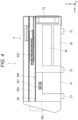
- Fig. 4 is a view of the inside of the housing 2 of the electronic endoscope processor 1 according to the embodiment as viewed from the side. As illustrated in Fig. 4 , the internal space of the housing 2 is partitioned into an upper space 20U (an example of a second space) and a lower space 20L (an example of a first space) by the partition plate 26. Heat generating components 41 and 42 are arranged in the lower space 20L.
- the aperture 263 of the partition plate 26 is preferably arranged in front. In this case, as illustrated in Fig. 4 , since the intake hole 252 and the aperture 263 of the partition plate 26 are separated from each other in the front-rear direction, heat generating components mounted in the upper space 20U are uniformly cooled when air at room temperature introduced from the intake hole 252 is directed to the aperture 263.
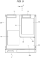
- Fig. 5 is a view of the lower space 20L of the housing 2 of the electronic endoscope processor 1 according to the embodiment as viewed from above.
- Fig. 6 is a view of the inside of the electronic endoscope processor 1 according to the embodiment as viewed from the front.
- an air flow adjusting plate 31 is provided in the lower space 20L of the housing 2.
- the air flow adjusting plate 31 is a plate standing upward from the bottom plate 24 of the housing 2, and is installed substantially parallel to a direction of an air flow toward the exhaust fans 71 and 72.
- the air flow adjusting plate 31 is arranged between the aperture 263 and the heat generating component 42 in the lower space 20L, and adjusts an air flow entering the lower space 20L from the aperture 263 to be directed to the heat generating component 42. Since the air flow adjusting plate 31 is provided, the air flow can be divided in accordance with the arrangement of the heat generating components 41 and 42 in the lower space 20L.
- the air flow adjusting plate 31 is formed to divide the air flow into two directions toward the respective two exhaust fans 71 and 72.
- an air flow adjusting plate for dividing an air flow may be arranged in the upper space 20U as necessary although not illustrated.
- a plurality of air flow adjusting plates can also be arranged.
- two air flow adjusting plates may be arranged in parallel in the same direction as the air flow adjusting plate 31 in order to divide the air flow entering the lower space 20L from the upper space 20U toward the respective exhaust fans.
- the air flow adjusting plate 32 may be provided so as to face the direction of the air flow toward the exhaust fan 72.
- the air flow adjusting plate 32 has an aperture 321 (an example of a second aperture) which is an aperture for adjusting a wind speed and/or a wind amount of an air flow directed to each of the heat generating components 42.
- an example in which two apertures 321 are formed is illustrated in the example illustrated in Fig. 6 , but the number of the apertures 321 is not limited thereto.
- the number of the apertures 321 and/or sizes of the apertures 321 can be set such that a wind amount and/or a wind speed corresponding to the heat generating components can be obtained.
- the number of the apertures 321 is preferably set in accordance with a position of each of the heat generating components 42.
- a shape of the aperture 321 is rectangular, but is not limited thereto, and can be a desired shape (for example, circular, elliptical, or polygonal) to adjust the air flow.
- Fig. 7 is a view for describing an air flow in the internal space (upper space and lower space) of the housing 2 of the electronic endoscope processor 1 according to the embodiment.
- Fig. 8 is a view for describing an air flow when the inside of the housing 2 of the electronic endoscope processor 1 according to the embodiment is viewed from the side.
- the air flow in the housing 2 of the electronic endoscope processor 1 is a flow of air in which outside air is introduced into the upper space from the intake hole 252 and exhausted from the exhaust fans 71 and 72 in the lower space.
- air flows F1 introduced from the intake holes 252 into the upper space become air flows F2 directed to the apertures 263 of the partition plate 26 while cooling the heat generating components arranged in the upper space, and are directed to the lower space.
- Air flows F3 are introduced into the lower space from the intake holes 251.
- the air flows F2 warmed by heat generated by the heat generating components in the upper space are mixed with the air flows F3 at room temperature, introduced from the intake holes 251, whereby the amount of heat temporarily decreases.
- the air flow adjusting plates 31 and 32 are provided in the lower space, one of the air flows F2 directed to the lower space from the apertures 263 formed at two locations flows toward the exhaust fan 71 as an air flow F4, and the other of the air flows F2 directed to the lower space flows toward the exhaust fan 72 as an air flow F4.
- the air flow adjusting plate 32 including the aperture 321 is provided in accordance with the heat generating components 41 and 42 arranged in the lower space, thereby adjusting wind amounts and/or wind speeds of the air flows F4.
- the size, position, shape, and the like of the aperture 321 of the air flow adjusting plate 32 are adjusted in accordance with the position of the heat generating component 42, thereby locally cooling the heat generating component 42.
- the housing 2 of the electronic endoscope processor 1 since an air flow flows from the intake hole 252 in the upper space toward the exhaust fans 71 and 72 arranged only in the lower space, the air flow does not become non-uniform between the upper space and the lower space, and the internal space of the housing can be cooled in a well-balanced manner. At this time, cooling performance can be adjusted by adjusting the wind amount and/or the wind speed of the air flow by the air flow adjusting plate in accordance with the arrangement of the heat generating components in the housing 2.
- a size of the intake hole 252 is set to be larger than a size of the intake hole 251. Since the intake hole 252 is larger, a lot of outside air can be introduced from the upper space 20U of the housing 2, and a flow rate and/or a flow velocity of the air flow reaching the exhaust fans 71 and 72 can be increased.
- the size of the intake hole 251 is set such that the air flow is the fastest in the lower space 20L and the upper space 20U.
- the inventor simulated the flow velocity of the air flow in the internal space of the housing 2 while changing sizes of the intake hole 251 and the intake hole 252.
- the size of the intake hole 252 through which outside air is introduced into the upper space 20U was reduced from a reference size to 1/2 and 1/3, the flow velocity in the upper space 20U decreased in both cases, and thus it has been confirmed that it is preferable to increase the size of the intake hole 252.
- the air flow can be set to be the fastest in the lower space 20L and the upper space 20U by adjusting the size of the intake hole 251.
- a turbulence generating structure that generates turbulence in the air flow passing through the aperture 263 of the partition plate 26 and/or the aperture 321 of the air flow adjusting plate 32 may be provided.
- Fig. 9 illustrates an example in which protrusions 264 and 322, which serve as the turbulence generating structure, are provided on peripheral edges of the aperture 263 and the aperture 321, respectively. Note that, as the turbulence generating structure, bending or a flap can be adopted in addition to the protrusions.
- the electronic endoscope processor of the present invention has been described above in detail, but the electronic endoscope processor of the present invention is not limited to the foregoing embodiment, and may of course be modified or altered in various ways in a range not deviating from the scope and spirit of the present invention.
- the present invention relates to a patent application of Japanese Patent Application No. 2022-120374 filed with the Japan Patent Office on July 28, 2022 , the entire contents of which are incorporated herein by reference.
Landscapes
- Health & Medical Sciences (AREA)
- Life Sciences & Earth Sciences (AREA)
- Physics & Mathematics (AREA)
- Surgery (AREA)
- Engineering & Computer Science (AREA)
- Optics & Photonics (AREA)
- Medical Informatics (AREA)
- General Health & Medical Sciences (AREA)
- Pathology (AREA)
- Nuclear Medicine, Radiotherapy & Molecular Imaging (AREA)
- Biomedical Technology (AREA)
- Heart & Thoracic Surgery (AREA)
- Biophysics (AREA)
- Molecular Biology (AREA)
- Animal Behavior & Ethology (AREA)
- Radiology & Medical Imaging (AREA)
- Public Health (AREA)
- Veterinary Medicine (AREA)
- Microelectronics & Electronic Packaging (AREA)
- Astronomy & Astrophysics (AREA)
- General Physics & Mathematics (AREA)
- Thermal Sciences (AREA)
- Endoscopes (AREA)
- Instruments For Viewing The Inside Of Hollow Bodies (AREA)
Abstract
Description
- The present invention relates to an electronic endoscope processor configured to acquire and process a captured image of a living tissue.
- An electronic endoscope system is used to observe or treat a living tissue inside a human body. The electronic endoscope system includes an electronic endoscope that captures an image of a living tissue with an image sensor and transmits the captured image to a processor, and the processor (electronic endoscope processor) that processes a signal of the captured image to create an image for display.
- In the electronic endoscope processor, a power supply circuit and a circuit board including an integrated circuit such as a CPU or a field-programmable gate array (FPGA) in order to secure high performance processing capability are used, and further, a light source device for observing a living tissue may be built in the processor. Since such a heat source is accommodated in a housing of the processor, various measures have been conventionally proposed in order to mitigate a temperature rise inside the processor due to a long-time operation.
- For example,
JP 2019-107291 A - However, in the exhaust mechanism described in
JP 2019-107291 A - Therefore, an object of the present invention is to provide an electronic endoscope processor capable of cooling an internal space of a housing in a well-balanced manner.
- One aspect of the present invention is an electronic endoscope processor including:
- a housing;
- a partition plate that partitions an internal space of the housing into a first space below and a second space above, the partition plate having a first aperture that is an aperture allowing the first space and the second space to communicate with each other; and
- an exhaust fan that is attached to the housing and exhausts air in the first space to the outside.
- A first intake hole through which outside air is acquired into the first space and a second intake hole through which outside air is acquired into the second space are formed in the housing.
- The electronic endoscope processor includes one or a plurality of heat generating components that are arranged in the first space and generate heat during operation. In this case, the electronic endoscope processor preferably includes an air flow adjusting plate that is arranged between the first aperture and each of the heat generating components in the first space and adjusts an air flow entering the first space from the first aperture to be directed to each of the heat generating components.
- A second aperture that is an aperture for adjusting a wind speed and/or a wind amount of the air flow directed to each of the heat generating components may be formed in the air flow adjusting plate.
- The second intake hole is preferably larger than the first intake hole.
- A size of the first intake hole is preferably set such that an air flow is the fastest in the first space and the second space.
- A peripheral edge of the first aperture may have a turbulence generating structure that generates turbulence in an air flow passing through the first aperture. A peripheral edge of the second aperture may have a turbulence generating structure that generates turbulence in an air flow passing through the second aperture.
- According to the above-described electronic endoscope processor, the internal space of the housing can be cooled in a well-balanced manner.
-
-
Fig. 1 is a block diagram illustrating an overall configuration of an electronic endoscope system of an embodiment. -
Fig. 2 is a perspective view and a rear view of the electronic endoscope processor according to the embodiment. -
Fig. 3 is a schematic exploded perspective view of the electronic endoscope processor according to the embodiment. -
Fig. 4 is a view of the inside of the electronic endoscope processor according to the embodiment as viewed from the side. -
Fig. 5 is a view of a lower space of a housing of the electronic endoscope processor according to the embodiment as viewed from above. -
Fig. 6 is a view of the inside of the electronic endoscope processor according to the embodiment as viewed from the front. -
Fig. 7 is a view for describing an air flow in an internal space of the electronic endoscope processor according to the embodiment. -
Fig. 8 is a view for describing an air flow when the inside of the electronic endoscope processor according to the embodiment is viewed from the side. -
Fig. 9 is a view illustrating a state in which a protrusion is provided in the electronic endoscope processor according to the embodiment. - Hereinafter, an electronic endoscope system according to an embodiment will be described.
- An electronic endoscope system according to the embodiment includes: an electronic endoscope (electronic scope) including an image sensor that acquires a captured image of a living tissue; and an electronic endoscope processor detachably connected to the electronic endoscope. The electronic endoscope processor is an electronic device that performs signal processing on the captured image of the living tissue to create an image for display.
-
Fig. 1 illustrates a schematic configuration of anelectronic endoscope system 100 according to the embodiment. As illustrated inFig. 1 , theelectronic endoscope system 100 includes anelectronic endoscope processor 1, anelectronic scope 6, and a monitor 8. Theelectronic endoscope processor 1 and theelectronic scope 6 are connected by a connector CON. - The
electronic endoscope processor 1 includes a system controller 11. The system controller 11 executes various programs stored in amemory 12 and integrally controls the entireelectronic endoscope system 100. Further, the system controller 11 is connected to anoperation panel 13. The system controller 11 changes operations of theelectronic endoscope system 100 and a parameter for each of the operations in accordance with an operator's instruction input to theoperation panel 13. - The
electronic endoscope processor 1 includes alight source device 14. Thelight source device 14 emits illumination light L for illuminating an object such as a living tissue in a body cavity. A light source of thelight source device 14 is, for example, a high luminance lamp (for example, a xenon lamp, a metal halide lamp, a mercury lamp, a halogen lamp, or the like) that emits white illumination light, a plurality of light emitting diodes emitting light in a wavelength band of a predetermined color, or a laser light source. The illumination light L emitted from thelight source device 14 is condensed onto an incident end face of a light carrying bundle (LCB) 61 by acondenser lens 15, and is incident into theLCB 61. - The illumination light L incident into the
LCB 61 propagates through theLCB 61. The illumination light L propagating through theLCB 61 is emitted from an exit end face of theLCB 61 arranged at a distal tip of theelectronic scope 6, and is applied to the object via alight distribution lens 62. Return light from the object illuminated with the illumination light L from thelight distribution lens 62 forms an optical image on a light receiving surface of a solid-state image sensor 64 via anobjective lens 63. - The solid-
state image sensor 64 is a single-plate color charge coupled device (CCD) image sensor having a Bayer pixel arrangement. The solid-state image sensor 64 accumulates an optical image formed by each of pixels on the light receiving surface, as charge corresponding to the amount of light, and generates and outputs image signals of Red (R), Green (G), and Blue (B). Note that the solid-state image sensor 64 is not limited to a CCD image sensor, and may be a complementary metal oxide semiconductor (CMOS) image sensor. - A driver
signal processing circuit 65 is provided in a connection portion of theelectronic scope 6. An image signal of the object is input to the driversignal processing circuit 65 from the solid-state image sensor 64 in a predetermined frame cycle. For example, the frame cycle is 1/30 seconds. The driversignal processing circuit 65 performs predetermined processing including A/D conversion on the image signal input from the solid-state image sensor 64 and outputs the processed image signal to animage processing unit 16 of theelectronic endoscope processor 1. - The
image processing unit 16 performs predetermined image processing to generate a video format signal, and outputs the video format signal to the monitor 8. - The
electronic endoscope processor 1 includes a lightsource control unit 17 that acquires luminance information of the image signal from theimage processing unit 16 and controls the intensity of the illumination light of thelight source device 14 based on the luminance information. - The light
source control unit 17 controls thelight source device 14 such that the intensity of the illumination light emitted from thelight source device 14 is high when brightness is low and the intensity of the illumination light emitted from thelight source device 14 is low when brightness is high. Accordingly, the brightness of the image signal received from the driversignal processing circuit 65 is controlled to be maintained constant. - The system controller 11 performs various calculations based on unique information of the
electronic scope 6, and generates a control signal. The system controller 11 controls operations and timings of various circuits in theelectronic endoscope processor 1 using the generated control signal such that processing suitable for theelectronic scope 6 connected to theelectronic endoscope processor 1 is performed. - Next, a structure of the
electronic endoscope processor 1 will be described. - In the
electronic endoscope processor 1, each of the system controller 11, theimage processing unit 16, and the lightsource control unit 17 is a heat generating component configured by a circuit board including a central processing unit (CPU), an application specific integrated circuit (ASIC), a field-programmable gate array (FPGA), or the like and generates heat with the operation of theelectronic endoscope processor 1. Thelight source device 14 is a heat generating component that generates heat with light emission of the light source. In addition, heat generating components such as a power supply board and a heat sink are mounted on theelectronic endoscope processor 1. - As described above, since the plurality of heat generating components need to be included in the housing constituting the
electronic endoscope processor 1, the inside of the housing is designed such that an internal space of the housing can be cooled in a well-balanced manner. -
Fig. 2 illustrates a perspective view and a rear view of theelectronic endoscope processor 1 according to the embodiment. - As illustrated in
Fig. 2 , ahousing 2 of theelectronic endoscope processor 1 includes afront surface portion 21, arear surface portion 22, atop plate 23, abottom plate 24, aleft side plate 25L, and aright side plate 25R, and has an appearance of a rectangular parallelepiped shape. A plurality oflegs 27 are attached to thebottom plate 24. - The
operation panel 13 is arranged on thefront surface portion 21. Theleft side plate 25L has an intake hole 251 (an example of a first intake hole) and an intake hole 252 (an example of a second intake hole) through which outside air is introduced into thehousing 2. Note that the intake holes 251 and 252 may also be symmetrically formed in theright side plate 25R although not visible inFig. 2 . In the following description, theleft side plate 25L and theright side plate 25R are described as a "side plate 25" when matters common to theleft side plate 25L and theright side plate 25R are referred to. - Two
exhaust fans rear surface portion 22 of thehousing 2. Theexhaust fans housing 2 from the intake holes 251 and 252. - Note that, in each drawing referred to in the following description, XYZ coordinate axes are described such that a direction from the
left side plate 25L toward theright side plate 25R is a +X direction, a direction from therear surface portion 22 toward thefront surface portion 21 is a +Y direction, and a direction from thebottom plate 24 toward thetop plate 23 is a +Z direction. - In the embodiment, each of the
intake hole 251 and theintake hole 252 is constituted by an assembly of a plurality of small holes. In the example illustrated inFig. 2 , a shape of each hole is a shape close to a flat ellipse, but is not limited thereto, and can be set to a circle, a polygon, or the like. - Next, an internal structure of the
housing 2 of theelectronic endoscope processor 1 will be described with reference toFigs. 3 to 6 . -
Fig. 3 is a schematic exploded perspective view of theelectronic endoscope processor 1 according to the embodiment. - As illustrated in
Fig. 3 , thehousing 2 of theelectronic endoscope processor 1 includes a box-shapedframe 20 including thefront surface portion 21, therear surface portion 22, and thebottom plate 24. Theleft side plate 25L, theright side plate 25R, thetop plate 23, and thepartition plate 26 are attached to theframe 20. - The
partition plate 26 and thetop plate 23 are fixed to theframe 20 in this order to partition the internal space of thehousing 2 into two spaces of an upper space and a lower space. That is, thehousing 2 of theelectronic endoscope processor 1 has a two-story structure by thepartition plate 26. - In the
frame 20, anaperture 201 is formed at a position corresponding to theintake hole 251. Accordingly, when the side plate 25 is attached to theframe 20, outside air can be introduced into the internal space (lower space) of thehousing 2 from theintake hole 251 and theaperture 201. - The
partition plate 26 has a pair ofside wall portions 261 so as to face theleft side plate 25L and theright side plate 25R, respectively, and an aperture 262 (an example of a first aperture) is formed in theside wall portion 261. Accordingly, when the side plate 25 is attached to theframe 20, outside air can be introduced into the internal space (upper space) of thehousing 2 from theintake hole 252 and theaperture 262. - As illustrated in
Fig. 3 , twoapertures 263 are formed in thepartition plate 26. Theexhaust fans aperture 263 is provided to move the air introduced from theintake hole 252 as an air flow from the upper space to the lower space of thehousing 2. Note that the number of theapertures 263 is two in the example illustrated inFig. 3 , but is not limited thereto, and the number of theapertures 263 can be appropriately set in order to generate a desired air flow. - In each of the upper space and the lower space of the
housing 2, heat generating components such as the circuit boards and the light source device of theelectronic endoscope processor 1 are mounted. Therefore, theelectronic endoscope processor 1 according to the embodiment is configured to cool these heat generating components in a well-balanced manner. - A structure in the
housing 2 of theelectronic endoscope processor 1 according to the embodiment will be further described with reference toFigs. 4 to 6 . -
Fig. 4 is a view of the inside of thehousing 2 of theelectronic endoscope processor 1 according to the embodiment as viewed from the side. As illustrated inFig. 4 , the internal space of thehousing 2 is partitioned into anupper space 20U (an example of a second space) and alower space 20L (an example of a first space) by thepartition plate 26. Heat generatingcomponents lower space 20L. - The
aperture 263 of thepartition plate 26 is preferably arranged in front. In this case, as illustrated inFig. 4 , since theintake hole 252 and theaperture 263 of thepartition plate 26 are separated from each other in the front-rear direction, heat generating components mounted in theupper space 20U are uniformly cooled when air at room temperature introduced from theintake hole 252 is directed to theaperture 263. -
Fig. 5 is a view of thelower space 20L of thehousing 2 of theelectronic endoscope processor 1 according to the embodiment as viewed from above.Fig. 6 is a view of the inside of theelectronic endoscope processor 1 according to the embodiment as viewed from the front. - In the embodiment, an air
flow adjusting plate 31 is provided in thelower space 20L of thehousing 2. The airflow adjusting plate 31 is a plate standing upward from thebottom plate 24 of thehousing 2, and is installed substantially parallel to a direction of an air flow toward theexhaust fans flow adjusting plate 31 is arranged between theaperture 263 and theheat generating component 42 in thelower space 20L, and adjusts an air flow entering thelower space 20L from theaperture 263 to be directed to theheat generating component 42. Since the airflow adjusting plate 31 is provided, the air flow can be divided in accordance with the arrangement of theheat generating components lower space 20L. - In the example illustrated in
Fig. 5 , the airflow adjusting plate 31 is formed to divide the air flow into two directions toward the respective twoexhaust fans - Note that an air flow adjusting plate for dividing an air flow may be arranged in the
upper space 20U as necessary although not illustrated. - A plurality of air flow adjusting plates can also be arranged. For example, in a case where three exhaust fans are provided in the
lower space 20L, two air flow adjusting plates may be arranged in parallel in the same direction as the airflow adjusting plate 31 in order to divide the air flow entering thelower space 20L from theupper space 20U toward the respective exhaust fans. - As illustrated in
Fig. 5 , for example, the airflow adjusting plate 32 may be provided so as to face the direction of the air flow toward theexhaust fan 72. - As illustrated in
Fig. 6 , the airflow adjusting plate 32 has an aperture 321 (an example of a second aperture) which is an aperture for adjusting a wind speed and/or a wind amount of an air flow directed to each of theheat generating components 42. Although an example in which twoapertures 321 are formed is illustrated in the example illustrated inFig. 6 , but the number of theapertures 321 is not limited thereto. The number of theapertures 321 and/or sizes of theapertures 321 can be set such that a wind amount and/or a wind speed corresponding to the heat generating components can be obtained. The number of theapertures 321 is preferably set in accordance with a position of each of theheat generating components 42. - In
Fig. 6 , a shape of theaperture 321 is rectangular, but is not limited thereto, and can be a desired shape (for example, circular, elliptical, or polygonal) to adjust the air flow. - It is preferable to adjust the size, shape, and position of the
aperture 321 to increase the wind speed of the air flow in terms of preventing dust from being accumulated or adhering onto each of theheat generating components 42. - Next, a cooling operation of the
electronic endoscope processor 1 will be described with reference toFigs. 7 and8 . -
Fig. 7 is a view for describing an air flow in the internal space (upper space and lower space) of thehousing 2 of theelectronic endoscope processor 1 according to the embodiment.Fig. 8 is a view for describing an air flow when the inside of thehousing 2 of theelectronic endoscope processor 1 according to the embodiment is viewed from the side. - The air flow in the
housing 2 of theelectronic endoscope processor 1 is a flow of air in which outside air is introduced into the upper space from theintake hole 252 and exhausted from theexhaust fans - Referring to
Fig. 7 , first, air flows F1 introduced from the intake holes 252 into the upper space become air flows F2 directed to theapertures 263 of thepartition plate 26 while cooling the heat generating components arranged in the upper space, and are directed to the lower space. Air flows F3 are introduced into the lower space from the intake holes 251. The air flows F2 warmed by heat generated by the heat generating components in the upper space are mixed with the air flows F3 at room temperature, introduced from the intake holes 251, whereby the amount of heat temporarily decreases. - Since the air
flow adjusting plates apertures 263 formed at two locations flows toward theexhaust fan 71 as an air flow F4, and the other of the air flows F2 directed to the lower space flows toward theexhaust fan 72 as an air flow F4. The airflow adjusting plate 32 including theaperture 321 is provided in accordance with theheat generating components aperture 321 of the airflow adjusting plate 32 are adjusted in accordance with the position of theheat generating component 42, thereby locally cooling theheat generating component 42. - As described above, in the
housing 2 of theelectronic endoscope processor 1 according to the embodiment, since an air flow flows from theintake hole 252 in the upper space toward theexhaust fans housing 2. - In the embodiment, a size of the
intake hole 252 is set to be larger than a size of theintake hole 251. Since theintake hole 252 is larger, a lot of outside air can be introduced from theupper space 20U of thehousing 2, and a flow rate and/or a flow velocity of the air flow reaching theexhaust fans - In the embodiment, the size of the
intake hole 251 is set such that the air flow is the fastest in thelower space 20L and theupper space 20U. - The inventor simulated the flow velocity of the air flow in the internal space of the
housing 2 while changing sizes of theintake hole 251 and theintake hole 252. First, when the size of theintake hole 252 through which outside air is introduced into theupper space 20U was reduced from a reference size to 1/2 and 1/3, the flow velocity in theupper space 20U decreased in both cases, and thus it has been confirmed that it is preferable to increase the size of theintake hole 252. Furthermore, when the size of theintake hole 251 through which outside air is introduced into thelower space 20L was set to (reduced to) 1/2 or (enlarged to) 3/2, the flow velocity of the air flow increased in both theupper space 20U and thelower space 20L when the size of theintake hole 251 was reduced, and the flow velocity of the air flow decreased in both theupper space 20U and thelower space 20L when the size of theintake hole 251 was increased. - From the above simulation results, it has been confirmed that the air flow can be set to be the fastest in the
lower space 20L and theupper space 20U by adjusting the size of theintake hole 251. - In the embodiment, a turbulence generating structure that generates turbulence in the air flow passing through the
aperture 263 of thepartition plate 26 and/or theaperture 321 of the airflow adjusting plate 32 may be provided. For example,Fig. 9 illustrates an example in whichprotrusions aperture 263 and theaperture 321, respectively. Note that, as the turbulence generating structure, bending or a flap can be adopted in addition to the protrusions. - The electronic endoscope processor of the present invention has been described above in detail, but the electronic endoscope processor of the present invention is not limited to the foregoing embodiment, and may of course be modified or altered in various ways in a range not deviating from the scope and spirit of the present invention.
- The present invention relates to a patent application of
Japanese Patent Application No. 2022-120374 filed with the Japan Patent Office on July 28, 2022
Claims (7)
- An electronic endoscope processor comprising:a housing;a partition plate that partitions an internal space of the housing into a first space below and a second space above, the partition plate having a first aperture that is an aperture allowing the first space and the second space to communicate with each other; andan exhaust fan that is attached to the housing and exhausts air in the first space to an outside,wherein a first intake hole through which outside air is acquired into the first space and a second intake hole through which outside air is acquired into the second space are formed in the housing.
- The electronic endoscope processor according to claim 1, further comprising:one or a plurality of heat generating components that are arranged in the first space and generate heat during operation; andan air flow adjusting plate that is arranged between the first aperture and each of the heat generating components in the first space and adjusts an air flow entering the first space through the first aperture to be directed to each of the heat generating components.
- The electronic endoscope processor according to claim 2, wherein
a second aperture that is an aperture for adjusting a wind speed and/or a wind amount of the air flow directed to each of the heat generating components is formed in the air flow adjusting plate. - The electronic endoscope processor according to any one of claims 1 to 3, wherein
the second intake hole is larger than the first intake hole. - The electronic endoscope processor according to any one of claims 1 to 3, wherein
a size of the first intake hole is set in such a manner that an air flow is fastest in the first space and the second space. - The electronic endoscope processor according to any one of claims 1 to 3, wherein
a peripheral edge of the first aperture has a turbulence generating structure that generates turbulence in an air flow passing through the first aperture. - The electronic endoscope processor according to claim 3, wherein
a peripheral edge of the second aperture has a turbulence generating structure that generates turbulence in an air flow passing through the second aperture.
Applications Claiming Priority (2)
| Application Number | Priority Date | Filing Date | Title |
|---|---|---|---|
| JP2022120374A JP7760467B2 (en) | 2022-07-28 | 2022-07-28 | Processor for electronic endoscope |
| PCT/JP2023/021007 WO2024024285A1 (en) | 2022-07-28 | 2023-06-06 | Electronic endoscope processor |
Publications (2)
| Publication Number | Publication Date |
|---|---|
| EP4563068A1 true EP4563068A1 (en) | 2025-06-04 |
| EP4563068A4 EP4563068A4 (en) | 2026-07-08 |
Family
ID=89706157
Family Applications (1)
| Application Number | Title | Priority Date | Filing Date |
|---|---|---|---|
| EP23846021.6A Pending EP4563068A4 (en) | 2022-07-28 | 2023-06-06 | ELECTRONIC ENDOSCOPE PROCESSOR |
Country Status (5)
| Country | Link |
|---|---|
| US (1) | US20250204768A1 (en) |
| EP (1) | EP4563068A4 (en) |
| JP (1) | JP7760467B2 (en) |
| CN (1) | CN119136722A (en) |
| WO (1) | WO2024024285A1 (en) |
Family Cites Families (15)
| Publication number | Priority date | Publication date | Assignee | Title |
|---|---|---|---|---|
| JPH04108422A (en) * | 1990-08-29 | 1992-04-09 | Olympus Optical Co Ltd | Cooling system for endoscope system apparatus |
| JP2806826B2 (en) * | 1995-06-14 | 1998-09-30 | 甲府日本電気株式会社 | Electronic device cooling structure |
| JP3623374B2 (en) * | 1998-09-28 | 2005-02-23 | オリンパス株式会社 | Endoscope light source device |
| HUP0201698A2 (en) * | 1999-06-01 | 2002-09-28 | Volker Dalheimer | Housing system for housing electronic components, especially a flat desktop pc or multimedia housing |
| JP3784674B2 (en) * | 2001-07-31 | 2006-06-14 | 三菱電機株式会社 | Electronic equipment |
| US7218517B2 (en) * | 2004-12-07 | 2007-05-15 | International Business Machines Corporation | Cooling apparatus for vertically stacked printed circuit boards |
| JP4810147B2 (en) * | 2005-07-19 | 2011-11-09 | オリンパス株式会社 | Endoscope device |
| JP4693925B2 (en) * | 2009-09-30 | 2011-06-01 | 株式会社東芝 | Electronics |
| WO2017175568A1 (en) * | 2016-04-04 | 2017-10-12 | オリンパス株式会社 | Endoscope device |
| WO2018216381A1 (en) * | 2017-05-22 | 2018-11-29 | オリンパス株式会社 | Cooling device |
| JP2019107291A (en) * | 2017-12-19 | 2019-07-04 | オリンパス株式会社 | Medical device for endoscope |
| JP2020130427A (en) * | 2019-02-15 | 2020-08-31 | Hoya株式会社 | Endoscope system |
| WO2021152746A1 (en) * | 2020-01-29 | 2021-08-05 | オリンパス株式会社 | Endoscope cooling device |
| JP2022120374A (en) | 2021-02-05 | 2022-08-18 | 凸版印刷株式会社 | storage container |
| WO2022260989A2 (en) * | 2021-06-07 | 2022-12-15 | Zodiac Pool Care Europe | Vessels such as swimming pools or spas omitting dedicated plumbed water-circulation systems |
-
2022
- 2022-07-28 JP JP2022120374A patent/JP7760467B2/en active Active
-
2023
- 2023-06-06 US US18/850,331 patent/US20250204768A1/en active Pending
- 2023-06-06 CN CN202380038155.1A patent/CN119136722A/en active Pending
- 2023-06-06 WO PCT/JP2023/021007 patent/WO2024024285A1/en not_active Ceased
- 2023-06-06 EP EP23846021.6A patent/EP4563068A4/en active Pending
Also Published As
| Publication number | Publication date |
|---|---|
| WO2024024285A1 (en) | 2024-02-01 |
| JP2024017617A (en) | 2024-02-08 |
| EP4563068A4 (en) | 2026-07-08 |
| JP7760467B2 (en) | 2025-10-27 |
| US20250204768A1 (en) | 2025-06-26 |
| CN119136722A (en) | 2024-12-13 |
Similar Documents
| Publication | Publication Date | Title |
|---|---|---|
| KR100916028B1 (en) | Projector unit with cooling fan | |
| US7920381B2 (en) | Interior cooling structure and ultrasound imaging apparatus | |
| JP6507560B2 (en) | projector | |
| JP6329708B2 (en) | Endoscope light source device | |
| CN101281354A (en) | Optical part cooling mechanism and projection type image display apparatus using the same | |
| US20250204768A1 (en) | Electronic endoscope processor | |
| US10638923B2 (en) | Cooling unit and light source apparatus for endoscope | |
| CN109643047B (en) | Image projection apparatus | |
| CN101281352B (en) | Exhaust mechanism and projection type image display device using the mechanism | |
| CN101281350B (en) | Light source lamp cooling mechanism and projection type image display device using the mechanism | |
| JP6246451B1 (en) | Endoscope device | |
| US20180206713A1 (en) | Endoscope lighting device | |
| EP4563069A1 (en) | Processor for electronic endoscope | |
| US11320134B2 (en) | Cooling device, light source device, and medical observation system | |
| JP2023002982A (en) | Distance measuring device and distance measuring system | |
| JP4575565B2 (en) | Endoscope light source unit | |
| JP2006171165A (en) | Air cooling system | |
| US10264227B2 (en) | Projection-type image display device | |
| US6808296B2 (en) | Cooling apparatus for optical engine assembly | |
| TWI587063B (en) | Projector | |
| CN111736413A (en) | Electronic device, projection device, and cooling control method | |
| WO2017033386A1 (en) | Illumination system and program | |
| JP2009206951A (en) | 3-ccd camera | |
| US8511832B2 (en) | Projection type image display apparatus with angled exhaust fan | |
| CN109643048A (en) | Image projection device |
Legal Events
| Date | Code | Title | Description |
|---|---|---|---|
| STAA | Information on the status of an ep patent application or granted ep patent |
Free format text: STATUS: THE INTERNATIONAL PUBLICATION HAS BEEN MADE |
|
| PUAI | Public reference made under article 153(3) epc to a published international application that has entered the european phase |
Free format text: ORIGINAL CODE: 0009012 |
|
| STAA | Information on the status of an ep patent application or granted ep patent |
Free format text: STATUS: REQUEST FOR EXAMINATION WAS MADE |
|
| 17P | Request for examination filed |
Effective date: 20240920 |
|
| AK | Designated contracting states |
Kind code of ref document: A1 Designated state(s): AL AT BE BG CH CY CZ DE DK EE ES FI FR GB GR HR HU IE IS IT LI LT LU LV MC ME MK MT NL NO PL PT RO RS SE SI SK SM TR |
|
| DAV | Request for validation of the european patent (deleted) | ||
| DAX | Request for extension of the european patent (deleted) | ||
| A4 | Supplementary search report drawn up and despatched |
Effective date: 20260605 |
|
| RIC1 | Information provided on ipc code assigned before grant |
Ipc: A61B 1/12 20060101AFI20260529BHEP Ipc: G02B 23/24 20060101ALI20260529BHEP Ipc: H05K 7/20 20060101ALI20260529BHEP Ipc: A61B 1/06 20060101ALI20260529BHEP Ipc: G02B 7/00 20210101ALN20260529BHEP |