EP4563056A1 - Pile, cleaning apparatus and cleaning system - Google Patents

Pile, cleaning apparatus and cleaning system Download PDF

Info

Publication number
EP4563056A1
EP4563056A1 EP23844748.6A EP23844748A EP4563056A1 EP 4563056 A1 EP4563056 A1 EP 4563056A1 EP 23844748 A EP23844748 A EP 23844748A EP 4563056 A1 EP4563056 A1 EP 4563056A1
Authority
EP
European Patent Office
Prior art keywords
docking station
charging
cleaning
base
clamp piece
Prior art date
Legal status (The legal status is an assumption and is not a legal conclusion. Google has not performed a legal analysis and makes no representation as to the accuracy of the status listed.)
Pending
Application number
EP23844748.6A
Other languages
German (de)
French (fr)
Inventor
Yongfei ZHOU
Xing Li
Binxiong LIANG
Xuchang HAO
Current Assignee (The listed assignees may be inaccurate. Google has not performed a legal analysis and makes no representation or warranty as to the accuracy of the list.)
Beijing Rockrobo Technology Co Ltd
Original Assignee
Beijing Rockrobo Technology Co Ltd
Priority date (The priority date is an assumption and is not a legal conclusion. Google has not performed a legal analysis and makes no representation as to the accuracy of the date listed.)
Filing date
Publication date
Priority claimed from CN202210901475.2A external-priority patent/CN117502987A/en
Priority claimed from CN202210901472.9A external-priority patent/CN117502986A/en
Application filed by Beijing Rockrobo Technology Co Ltd filed Critical Beijing Rockrobo Technology Co Ltd
Publication of EP4563056A1 publication Critical patent/EP4563056A1/en
Pending legal-status Critical Current

Links

Images

Classifications

    • AHUMAN NECESSITIES
    • A47FURNITURE; DOMESTIC ARTICLES OR APPLIANCES; COFFEE MILLS; SPICE MILLS; SUCTION CLEANERS IN GENERAL
    • A47LDOMESTIC WASHING OR CLEANING; SUCTION CLEANERS IN GENERAL
    • A47L11/00Machines for cleaning floors, carpets, furniture, walls, or wall coverings
    • A47L11/40Parts or details of machines not provided for in groups A47L11/02 - A47L11/38, or not restricted to one of these groups, e.g. handles, arrangements of switches, skirts, buffers, levers
    • A47L11/4091Storing or parking devices, arrangements therefor; Means allowing transport of the machine when it is not being used
    • AHUMAN NECESSITIES
    • A47FURNITURE; DOMESTIC ARTICLES OR APPLIANCES; COFFEE MILLS; SPICE MILLS; SUCTION CLEANERS IN GENERAL
    • A47LDOMESTIC WASHING OR CLEANING; SUCTION CLEANERS IN GENERAL
    • A47L11/00Machines for cleaning floors, carpets, furniture, walls, or wall coverings
    • A47L11/24Floor-sweeping machines, motor-driven
    • AHUMAN NECESSITIES
    • A47FURNITURE; DOMESTIC ARTICLES OR APPLIANCES; COFFEE MILLS; SPICE MILLS; SUCTION CLEANERS IN GENERAL
    • A47LDOMESTIC WASHING OR CLEANING; SUCTION CLEANERS IN GENERAL
    • A47L11/00Machines for cleaning floors, carpets, furniture, walls, or wall coverings
    • A47L11/40Parts or details of machines not provided for in groups A47L11/02 - A47L11/38, or not restricted to one of these groups, e.g. handles, arrangements of switches, skirts, buffers, levers
    • A47L11/4002Installations of electric equipment
    • A47L11/4005Arrangements of batteries or cells; Electric power supply arrangements
    • AHUMAN NECESSITIES
    • A47FURNITURE; DOMESTIC ARTICLES OR APPLIANCES; COFFEE MILLS; SPICE MILLS; SUCTION CLEANERS IN GENERAL
    • A47LDOMESTIC WASHING OR CLEANING; SUCTION CLEANERS IN GENERAL
    • A47L11/00Machines for cleaning floors, carpets, furniture, walls, or wall coverings
    • A47L11/28Floor-scrubbing machines, motor-driven
    • A47L11/282Floor-scrubbing machines, motor-driven having rotary tools

Definitions

  • the present disclosure relates to the field of automatic cleaning technologies, and specifically, to a docking station, a cleaning device and a cleaning system.
  • the floor scrubber includes a device body and a cleaning base body.
  • a water recycling tank for example, a waste water tank and a cleaning liquid tank (e.g., a clean water tank), and a main fan used for suction are disposed in the device body.
  • the cleaning base body includes a cleaning brushroll used for scrubbing. Cleaning liquid, for example, water, is sprayed onto the cleaning brushroll through a built-in water pipe. The cleaning brushroll rotates at a high speed to mop a floor.
  • the floor scrubber needs to be cooperatively used with a matched docking station.
  • the docking station can support the floor scrubber parked thereon, and perform some maintenance work such as charging, self-cleaning, and drying.
  • Embodiments of the present disclosure provide a docking station, a cleaning device and a cleaning system.
  • the embodiments of the present disclosure provide a docking station.
  • the docking station is configured to support a cleaning device and includes:
  • the embodiments of the present disclosure provide a cleaning device.
  • the cleaning device is configured to be supported by a docking station for charging, and includes:
  • the embodiments of the present disclosure provide a cleaning system.
  • the cleaning system includes:
  • a cleaning device for example, a floor scrubber, generally includes a device body and a cleaning base body.
  • the cleaning device is generally provided with a water recycling tank, for example, a waste water tank and a cleaning liquid tank (e.g., a clean water tank), and a main fan used for suction.
  • the cleaning base body includes one, two, or more cleaning brushrolls used for scrubbing.
  • Cleaning liquid for example, water, is dispensed onto the cleaning brushroll having fluff and/or onto a surface to be cleaned through a built-in water pipe.
  • the cleaning brushroll rotates at a high speed to mop the surface to be cleaned.
  • a negative pressure is formed in a device air duct of the cleaning device by the main fan, enabling that waste water (that may include solid garbage) on the surface to be cleaned is sucked in through a waste water suction opening of the cleaning device and is pumped into the waste water tank.
  • waste water that may include solid garbage
  • the foregoing waste water recycling path forms a part of the device air duct of the cleaning device.
  • the cleaning device is generally placed back onto a docking station to be supported by the docking station.
  • Self-cleaning of the device for example, washing of the cleaning brushroll and/or drying of the cleaning brushroll, may be performed on the docking station.
  • a charging operation may also be performed on the docking station.
  • the docking station is usually of an integrated structure that has a relatively large size. In this case, a relatively large package needs to be equipped.
  • an accommodation groove on a base of the docking station is configured to accommodate the cleaning base body of the cleaning device. The cleaning brushroll of the cleaning base body needs to be washed in the accommodation groove. Dirt exists in the accommodation groove, particularly, in a brushroll groove corresponding to the cleaning brushroll.
  • the integrated structure of the docking station is not conductive to washing of the accommodation groove, particularly, the brushroll groove.
  • electronic components such as a charging wire, a circuit board and a fan exist in the docking station. Therefore, when the docking station of the integrated structure is washed, the electronic components have the risk of wading. In addition, because the size of the integrated structure is too large, the integrated structure is not conductive to cleaning.
  • the present disclosure provides a docking station.
  • the docking station is configured to support a cleaning device and includes a station body and a detachable tray.
  • the station body includes a base tray and a support base disposed on the base tray.
  • the support base is configured to support a device body of the cleaning device.
  • the detachable tray is configured to be detachably connected with the base tray.
  • the detachable tray is connected to the base tray to form an accommodation groove.
  • the accommodation groove is configured to accommodate a cleaning base body of the cleaning device.
  • the detachable tray is provided with a brushroll groove configured to accommodate a cleaning brushroll of the cleaning base body.
  • the detachable tray further includes a water blocking rib(s) disposed on one side or two sides of the brushroll groove.
  • the docking station includes the station body and the detachable tray.
  • the detachable tray is detachably connected to the base tray of the station body, which can reduce a package size of the docking station.
  • the detachable tray may be demounted and separated from the station body, facilitating a user to clean the detachable tray.
  • the detachable tray is provided with the brushroll groove and the water blocking ribs disposed on the two sides of the brushroll groove, so that when the cleaning device performs, on the docking station, an operation of washing the cleaning brushroll, cleaning liquid can be kept in the brushroll groove as much as possible, thereby avoiding the cleaning liquid to be spilled into another portion of the accommodation groove.
  • FIG. 1 is a schematic structural diagram of a docking station provided by some embodiments of the present disclosure, where the docking station is in a connected state.
  • FIG. 2 is a schematic structural diagram of a docking station provided by some embodiments of the present disclosure, where the docking station is in a connected state. The docking station shown in FIG. 2 and the docking station shown in FIG. 1 are taken from different viewing angles.
  • FIG. 3 is a schematic structural diagram of a docking station provided by some embodiments of the present disclosure, where the docking station is in a demounted state.
  • FIG. 4 is a schematic structural diagram of a docking station provided by some embodiments of the present disclosure, where the docking station is in a demounted state. The docking station shown in FIG.
  • the docking station 10 is configured to support a cleaning device.
  • the cleaning device is a floor scrubber. After finishing a cleaning operation, the floor scrubber may be placed back onto the docking station 10 for supporting.
  • Various operations such as charging, washing a cleaning brushroll, and/or drying the cleaning brushroll may be performed on the docking station.
  • the docking station 10 includes a station body 13 and a detachable tray 111 that are detachably connected with each other.
  • the station body 13 includes a base tray 112 and a support base 12.
  • the support base 12 is disposed on the base tray 112.
  • the support base 12 extends from a surface of the base tray 112 along a direction substantially perpendicular to the base tray 112 and away from the base tray 112.
  • the support base 12 and the base tray 112 may be of an integrated structure or may be of separated structures.
  • the support base 12 is configured to support a device body of the cleaning device. When the cleaning device is placed on the docking station 10, the support base 12 supports the device body of the cleaning device.
  • the detachable tray 111 is configured to be detachably connected with the base tray 112, and the detachable tray 111 and the base tray 112 jointly form a base 11 of the docking station 10.
  • the base 11 When the detachable tray 111 is connected to the base tray 112 to form the complete base 11, the base 11 is provided with an accommodation groove 14.
  • the accommodation groove 14 is configured to accommodate a cleaning base body of the cleaning device.
  • the base 11 supports and accommodates the cleaning base body of the cleaning device.
  • the cleaning base body is at least partially accommodated in the accommodation groove 14 to facilitate a self-washing operation, on the docking station 10, of the cleaning brushroll on the cleaning base body, thereby removing stains on the cleaning brushroll.
  • the detachable tray 111 is provided with a brushroll groove 1111 configured to accommodate the cleaning brushroll of the cleaning base body.
  • the detachable tray further includes water blocking ribs 1112 disposed on two sides of the brushroll groove.
  • the number of the brushroll groove 1111 is one or more and is matched with the number of the cleaning brushroll of the cleaning device.
  • one brushroll groove 1111 may correspond to one or more cleaning brushrolls.
  • the cleaning brushroll may perform a washing operation in the brushroll groove 1111 by using cleaning liquid.
  • the water blocking rib 1112 is configured to block the cleaning liquid from spilling outwards from the brushroll groove 1111 when the cleaning brushroll performs a self-washing operation.
  • the detachable tray 111 is detachably connected to the base tray 112 of the station body 13. After being demounted, the detachable tray 111 and the base tray 112 can be placed in a more flexible manner, so that space can be utilized more properly. Therefore, the design flexibility of a package is higher. For example, a relatively small package may be used for the docking station 10 that is in the demounted state, thereby reducing package costs. In addition, for the brushroll groove in which dirt is easy to accumulate, because the detachable tray 111 may be demounted and separated from the station body 13, a user may wash the detachable tray 111 after the detachable tray 111 is demounted. This facilitates washing.
  • the base tray 112 includes a first fixing clamp piece 1121.
  • the first fixing clamp piece 1121 extends from a side wall, namely, a connecting side wall, of the base tray 112 along a direction away from the support base 12.
  • the connecting side wall is, for example, a side wall of the base tray 112 away from the support base 12.
  • the detachable tray 111 includes a second fixing clamp piece 1113.
  • the second fixing clamp piece 1113 is configured to be detachably matched and clamped with the first fixing clamp piece 1121, thereby enabling the detachable tray 111 to be connected to the base tray 112.
  • the detachable tray 111 may be conveniently mounted to the base tray 112 or demounted from the base tray 112.
  • first fixing clamp pieces 1121 there are a plurality of first fixing clamp pieces 1121.
  • the plurality of first fixing clamp pieces 1121 are uniformly disposed along a connecting side wall of the base tray 112, for example, the connecting side wall is a side wall of the base tray 112 away from the support base 12.
  • the plurality of second fixing clamp pieces 1113 are in a one-to-one correspondence with the plurality of first fixing clamp pieces 1121. Two or more pairs of the first fixing clamp pieces 1121 and the second fixing clamp pieces 1113 that are matched with each other can make the detachable tray 111 and the base tray 112 be connected firmly. After the detachable tray 111 and the base tray 112 are connected, their positions are relatively fixed.
  • one of the first fixing clamp piece 1121 and the second fixing clamp piece 1113 includes a T-shaped clamping groove; the other one of the first fixing clamp piece 1121 and the second fixing clamp piece 1113 includes a T-shaped insert; and the T-shaped clamping groove and the T-shaped insert are configured to be matched and clamped with each other.
  • the T-shaped clamping groove is a clamping groove having a specific structure.
  • a section, in a plane perpendicular to a first direction, of the clamping groove is T-shaped, as shown in FIG. 3 and FIG. 4 .
  • the first direction is a vertical direction Y.
  • the plane perpendicular to the first direction is a horizontal plane.
  • the T-shaped insert is an insert having a specific structure.
  • a section, in a plane perpendicular to a first direction, of the insert is T-shaped, as shown in FIG. 3 and FIG. 4 .
  • the first direction is a vertical direction Y.
  • the plane perpendicular to the first direction is a horizontal plane.
  • the first fixing clamp piece 1121 includes a T-shaped clamping groove; and the second fixing clamp piece includes a T-shaped insert.
  • the detachable tray 111 may be moved towards the base tray 112 along the first direction Y until the detachable tray 111 and the base tray 112 are connected together.
  • the station body 13 is placed on an operating surface, for example, a horizontal floor; then, the detachable tray 111 is moved towards the horizontal floor along the vertical direction from top to bottom; and the second fixing clamp piece 1113 is aligned and in plug-in connection with the corresponding first fixing clamp piece 1121.
  • the detachable tray 111 may be moved away from the base tray 112 along the first direction Y.
  • the detachable tray 111 is moved away from the base tray 112 along the vertical direction from bottom to top.
  • the base tray 112 and the detachable tray 111 can be prevented from moving relative to each other in a horizontal direction. This can further make the base tray 112 and the detachable tray 111 be firmly connected with each other.
  • the base tray 112 includes a first positioning clamp piece 1122.
  • the first positioning clamp piece 1122 is disposed on the connecting side wall of the base tray 112, for example, the side wall of the base tray 112 away from the support base 12.
  • the detachable tray 111 further includes a second positioning clamp piece 1114 configured to be clamped with the first positioning clamp piece 1122, thereby connecting the detachable tray 111 and the base tray 112 in position.
  • the first positioning clamp piece 1122 is disposed on at least one of two ends of the connecting side wall of the base tray.
  • the first positioning clamp piece 1122 is disposed on each of the two ends of the side wall, away from the support base, of the base tray.
  • one of the first positioning clamp piece 1122 and the second positioning clamp piece 1114 includes a positioning clamp hole; and the other one of the first positioning clamp piece 1122 and the second positioning clamp piece 1114 includes a positioning snap.
  • the first positioning clamp piece 1122 includes the positioning clamp hole
  • the second positioning clamp piece 1114 includes the positioning snap.
  • the detachable tray 111 includes a blocking arm 1115 that is disposed on at least one end of the brushroll groove 1111 and configured to prevent the cleaning brushroll of the cleaning device from slipping.
  • the cleaning device is generally placed back onto the docking station to be supported by the docking station.
  • the cleaning brushroll can be washed on the docking station.
  • the cleaning brushroll is at least partially accommodated in the brushroll groove 1111.
  • the self-washing operation of the cleaning brushroll is mainly performed in the brushroll groove. In the washing process, the cleaning brushroll needs to rotate.
  • the blocking arm 1115 is disposed at the end of the brushroll groove and thus can prevent the cleaning brushroll from slipping.
  • the blocking arm 1115 has a greater height than a side wall of the accommodation groove 14.
  • FIG. 5 is a schematic structural diagram of a cleaning system provided by some embodiments of the present disclosure, where a cleaning device is supported by a docking station.
  • FIG. 6 is a schematic structural diagram of a cleaning system provided by some embodiments of the present disclosure, where a cleaning device is separated from a docking station.
  • the cleaning device 20 is matched with the docking station 10.
  • the cleaning device 20 includes a cleaning base body 21, a device body 22 and a handle assembly 23.
  • the device body 22 is disposed above the cleaning base body 21, and is movably connected to the cleaning base body 21, for example, pivotally connected to the cleaning base body 21.
  • the handle assembly 23 is connected to an end of the device body 22 away from the cleaning base body 21 and is used for being grasped by a user during an operation. The user grasps the handle assembly 23, thereby controlling the cleaning base body 21 to execute a cleaning task on a surface to be cleaned, for example, on a floor.
  • the device body 22 extends lengthwise.
  • the handle assembly 23 is connected to an upper end of the device body 22.
  • the cleaning base body 21 is connected to a lower end of the device body 22.
  • the device body 22 is pivotally connected to the cleaning base body 21, enabling the handle assembly 23 and the device body 22 to rotate relative to the cleaning base body 21, thereby changing an operating angle and flexibly adjusting a washing posture.
  • the cleaning base body 21 includes a cleaning component, for example, the cleaning brushroll 211, disposed at the bottom of the cleaning base body 21.
  • the number of the cleaning brushroll 211 is one or more, for example, two or three.
  • the cleaning brushroll 211 can rotate at a high speed to mop a floor.
  • the cleaning device 20, for example, a floor scrubber further includes a clean water tank 26 and a waste water tank 25, both of which are, for example, disposed on the device body 22.
  • the clean water tank 26 accommodates cleaning liquid, for example, cleaning water, and may provide the cleaning water for the cleaning brushroll 211 through a clean water pipeline to wet a surface of the cleaning brushroll 211, thereby enabling the cleaning brushroll 211 to perform wet cleaning on the surface to be cleaned.
  • the waste water tank 25 is configured to accommodate recycled waste water. When the cleaning brushroll 211 performs wet cleaning, waste water is generated on the surface that is cleaned. The waste water may be recycled into the waste water tank 25 through a waste water recycling pipeline.
  • the cleaning device 20 is generally placed on the docking station 10.
  • the docking station 10 supports and fixes the cleaning device 20.
  • an end of the support base 12 away from the base tray 112 is provided with a support groove 121.
  • the support groove 121 is configured to accommodate a part of the device body 22 of the cleaning device 20 to support the device body 22.
  • the support groove 121 is configured to accommodate an end of the device body 22 of the cleaning device 20 away from the handle assembly 23.
  • the support groove 121 supports the device body 22, the accommodation groove on the base 11 accommodates and supports the cleaning base body 21 of the cleaning device 20, and the cleaning brushroll 211 on the cleaning base body 21 is accommodated in the brushroll groove 1111.
  • the cleaning device 20 may further perform maintenance operations such as charging, self-cleaning and drying.
  • the docking station 10 may include a first charging/communication interface; the cleaning device 20 may include a second charging/communication interface; and the first charging/communication interface is matched and connected with the second charging/communication interface, thereby implementing a charging/communication function between the cleaning device 20 and the docking station 10.
  • the charging/communication function herein is at least one of a charging function or a communication function.
  • the character "/" denotes and/or.
  • the first charging/communication interface includes at least one first charging/communication terminal.
  • the at least one first charging/communication terminal is a female terminal or a male terminal.
  • the second charging/communication interface on the cleaning device 20 is correspondingly provided with a matched male terminal; or when the first charging/communication terminal is the male terminal, the second charging/communication interface on the cleaning device 20 is correspondingly provided with a matched female terminal.
  • the male terminal and the female terminal that are matched with each other are disposed on the docking station 10 and the cleaning device 20 respectively, the cleaning device 20 is enabled to have a good electrical path when performing a maintenance operation.
  • the plurality of first charging/communication terminals may be arranged regularly. All the first charging/communication terminals may be terminals of the same type, for example, charging terminals, communication terminals, or time division multiplexing composite terminals of charging terminals and communication terminals. Alternatively, some of the first charging/communication terminals are charging terminals, and the other first charging/communication terminals are communication terminals.
  • the first charging interface 122 is disposed in the support groove 121, and the first charging interface 122 is configured to be matched and connected with the second charging interface on the device body 22, thereby charging the device body 22.
  • the cleaning device may be placed back onto the docking station for charging.
  • a charging terminal in a charging interface on the docking station is usually exposed outside, and thus is easily affected by moisture in an external environment. As a result, a charging path becomes faulty.
  • the charging terminal is exposed outside, in a case that the user spills water onto the charging terminal by accident during usage, an operating circuit is prone to short circuit if accumulated water is not removed timely. As a result, the device is damaged.
  • some embodiments of the present disclosure further provide a docking station.
  • the docking station is configured to support a cleaning device, and charge the cleaning device and/or communicate with the cleaning device.
  • the docking station includes: a base configured to support a cleaning base body of the cleaning device, and a support base disposed on the base and configured to support a device body of the cleaning device.
  • the support base includes a first charging/communication interface.
  • the first charging/communication interface includes: a first charging holder provided with a cavity, a female/male terminal disposed in the cavity and configured to be in plug-in connection with a male/female terminal on the cleaning device, and a water-proof layer, for example, a water-proof flexible plastic layer coating at least a part of the first charging holder to protect the female/male terminal.
  • the water-proof flexible plastic layer is used to protect a female charging terminal in the cavity, thereby protecting the female charging terminal from being affected by external moisture and preventing the female charging terminal from being in contact with electrically conductive liquid.
  • the first charging/communication interface is a first charging interface
  • the second charging/communication interface is a second charging interface
  • the female/male terminal is a female charging terminal
  • the male/female terminal is a male charging terminal as an example.
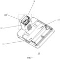
  • FIG. 7 is a schematic structural diagram of a docking station provided by some embodiments of the present disclosure, where the docking station is in a connected state.
  • the docking station shown in FIG. 7 and the docking stations shown in FIG. 1 and FIG. 2 are taken from different viewing angles.
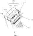
  • FIG. 8 is a schematic enlarged diagram of a region M in FIG. 7 .
  • FIG. 9 is a sectional view of a part of the region M shown in FIG. 8 .
  • FIG. 10 is a schematic enlarged diagram of a part of FIG. 9 .
  • the docking station 10 supports the cleaning device 20 and charges the cleaning device 20.
  • the docking station 10 includes a base 11 and a support base 12.
  • the base 11, for example, is provided with an accommodation groove 14.
  • the accommodation groove 14 is configured to accommodate a cleaning base body 21 of the cleaning device 20.
  • the support base 12 is disposed on the base 11 and is configured to support a device body 22 of the cleaning device 20.
  • the support base 12, for example, extends from an upper surface of the base 11 along a direction substantially perpendicular to the base 11 and away from the base 11.
  • the support base 12 includes a first charging interface 122 that is configured to be connected to a second charging interface on the cleaning device 20, thereby charging the cleaning device 20.
  • the first charging interface 122 includes a first charging holder 1221, a female charging terminal 1222 and a water-proof flexible plastic layer 1223.
  • the first charging interface 122 is disposed in a support groove 121 of the support base 12.
  • the first charging interface 122 extends from a bottom of the support groove 121 along a direction away from the base 11.
  • the second charging interface on the cleaning device 20, for example, is at an end of the device body 22 away from the handle assembly 23.
  • the support base 12 supports the device body 22, the device body 22 is partially accommodated in the support groove 121, and the first charging interface 122 is connected with the second charging interface on the cleaning device 20, thereby performing a charging operation.
  • the first charging holder 1221 is provided with a cavity 12211.
  • the female charging terminal 1222 is disposed in the cavity 12211 and is configured to be in plug-in connection with a male charging terminal of the second charging interface on the cleaning device 20, thereby charging the cleaning device 20.
  • the water-proof flexible plastic layer 1223 coats at least a part of the first charging holder 1221 to protect the female charging terminal 1222, thereby avoiding the following problem to ensure charging performance of the first charging interface 122: external moisture or liquid is in contact with the female charging terminal 1222 as the female charging terminal 1222 is directly exposed outside.
  • the cavity 12211 is provided with a cavity inlet 122111.
  • the cavity inlet 122111 is, for example, disposed at an end of the cavity 12211 away from the base 11, and configured to guide the male charging terminal into the cavity 12211 for plug-in connection with the female charging terminal 1222.
  • the cavity inlet 122111 is, for example, a structure that gradually broadens in a direction away from the cavity, so that the male charging terminal can be conveniently guided into the cavity 12211.
  • the water-proof flexible plastic layer 1223 includes a water-proof flexible plastic head 12231.
  • the water-proof flexible plastic head 12231 is disposed on a side of the cavity 12211 away from the base 11.
  • the water-proof flexible plastic head 12231 is configured to be switchable between an open state and a closed state.
  • the male charging terminal presses the water-proof flexible plastic head 12231 to make the water-proof flexible plastic head 12231 be in the open state, and the male charging terminal passes through the water-proof flexible plastic head 12231 and enters the cavity 12211 to be in plug-in connection with the female charging terminal 1222.
  • the water-proof flexible plastic head 12231 is in the closed state to protect the female charging terminal 1222 in the cavity 12211.
  • the water-proof flexible plastic head 12231 is made of an elastic material and, for example, is provided with a notch, such as a cross-shaped notch. Under the action of no external force, the water-proof flexible plastic head is in the closed state.
  • the male charging terminal of the cleaning device 20 is abutted against and exerts pressure on the water-proof flexible plastic head 12231, enabling the water-proof flexible plastic head 12231 to be in the open state.
  • the male charging terminal may pass through the water-proof flexible plastic head 12231 to enter the cavity 12211 and be in plug-in connection with the female charging terminal 1222, thereby forming an electrical path for charging the cleaning device 20.
  • a notch wall of the water-proof flexible plastic head 12231 is tightly attached to a side wall of the male charging terminal, which prevents intrusion of external liquid such as water, and can also implement sealing and water-proof functions in a charging process.
  • the water-proof flexible plastic layer may also be made of a material that has similar properties as the flexible plastic, and the similar properties refer to being water proof and provided with elasticity.
  • the plurality of female charging terminals 1222 may be arranged regularly. As shown in FIG. 7 to FIG. 10 , four female charging terminals 1222 are uniformly arranged in a row. In other embodiments, the plurality of female charging terminals 1222 may also be arranged in two or more rows.
  • the first charging interface 122 further includes a guide pillar 1224 that is disposed on the first charging holder 1221.
  • the guide pillar 1224 extends from the first charging holder 1221 towards a direction away from the base 11.
  • the guide pillar 1224 is configured to be inserted into a guide hole of the cleaning device 20, enabling the female charging terminal 1222 and the male charging terminal to be aligned with each other, thereby facilitating accurate connecting between the female charging terminal 1222 and the male charging terminal.
  • the first charging holder 1221 includes a charging holder body 12212 and a protruding portion 12213.
  • the protruding portion 12213 is disposed on the charging holder body 12212.
  • the cavity 12211 extends from an interior of the charging holder body 12212 into the protruding portion 12213.
  • the guide pillar 1224 is also disposed on the charging holder body 12212 and is spaced from the protruding portion 12213. In some embodiments, the number of the guide pillar 1224 is one or more, for example, two.
  • the two guide pillars 1224 are disposed on two sides of the protruding portion 12213 respectively, and correspond to two guide holes of the cleaning device 20 respectively.
  • Limitations to shapes of the guide pillar and the guide hole are not described. Only the following is indicated: the guide pillar and the guide hole are of a convex structure and a concave structure respectively, and are matched with each other.
  • the guide pillar may be a protrusion of any shape, such as a cylinder, a circular cone or a frustum. Accordingly, the guide hole is designed, based on the shape of the guide pillar, to be a groove having a matched shape.
  • the guide pillar 1224 may be inserted into the guide hole of the cleaning device 20 for guiding of alignment, enabling the female charging terminal 1222 and the male charging terminal to be aligned with each other. This avoids damage to a charging connector caused by misplacement of the charging terminals, repeated trials, or the like.
  • FIG. 11 is a schematic diagram of a partial structure of a device body of a cleaning device provided by some embodiments of the present disclosure.
  • the partial structure is a partial structure of the cleaning device 20 shown in FIG. 6 which is a bottom view.
  • FIG. 12 is a schematic structural diagram of a section on which a first charging/communication interface is in plug-in connection with a second charging/communication interface provided by some embodiments of the present disclosure.
  • the cleaning device 20 is configured to be supported by the docking station 10 for charging, and includes a cleaning base body 21 and a device body 22.
  • the device body 22 is disposed above the cleaning base body 21, and is movably connected to the cleaning base body 21, for example, pivotally connected to the cleaning base body 21.
  • the cleaning base body 21 includes a cleaning brushroll 211.
  • the cleaning device 20 may further include a handle assembly 23 that is connected to an end of the device body 22 away from the cleaning base body 21 and is used for being grasped by a user during an operation.
  • the device body 22 includes a second charging interface 221.
  • the second charging interface 221 is, for example, disposed at an end of the device body 22 away from the handle assembly 23.
  • the second charging interface 221 includes a second charging holder 2211 and a male charging terminal 2212.
  • the male charging terminal 2212 is disposed on the second charging holder 2211 and is configured to be in plug-in connection with the female charging terminal 1222 on the docking station 10, thereby forming a charging path for charging the cleaning device 20.
  • the second charging holder 2211 is provided with a recess portion 22111; the male charging terminal 2212 is at least partially disposed in the recess portion 22111; and the male charging terminal 2212 extends from a bottom surface of the recess portion 22111 towards a direction away from the device body 22.
  • the protruding portion 12213 of the first charging holder 1221 is at least partially inserted into the recess portion 22111.
  • the shape of the protruding portion 12213 is matched with that of the recess portion 22111, enabling the first charging interface 122 and the second charging interface 221 to be firmly connected with each other.
  • the second charging holder 2211 is provided with a guide hole 22112, and the guide hole 22112 is configured to accommodate the guide pillar 1224 of the docking station 10, enabling the male charging terminal 2212 and the female charging terminal 1222 to be aligned with each other. This avoids damage to a charging connecter caused by misplacement of the charging terminals, repeated trials, or the like.
  • the number of the guide hole 22112 corresponds to that of the guide pillar 1224, and may be one or more, for example, two.
  • the two guide holes are disposed on two sides of the recess portion 22111 respectively.
  • the second charging interface 221 further includes a reset spring 2213.
  • the reset spring 2213 is disposed in the guide hole 22112 and is configured to push against the guide pillar 1224, thereby enabling the guide pillar 1224 to trend to be separated from the guide hole 22112. Due to the arrangement of the reset spring, the following problem can be avoided: it is difficult to separate the second charging interface 221 from the first charging interface 122. Specifically, the following problem is prevented: the second charging interface 221 is clamped tightly with the first charging interface 122, and thus it is difficult to separate the cleaning device 20 from the docking station 10.
  • the reset spring When the cleaning device 20 is placed on the docking station 10 for charging, the reset spring is enabled to be in a compressed state under the action of the self-weight of the cleaning device 20, and at the same time, the second charging interface 221 is enabled to be in plug-in connection with the first charging interface 122 in place, so that poor connection between charging terminals can be avoided.
  • the reset spring may provide a force whose direction is opposite to that of gravity of the cleaning device 20, which can overcome a frictional force generated due to tight clamping between the male charging terminal 2212 and the female charging terminal 1222. Therefore, the user can separate the cleaning device 20 from the docking station 10 by exerting a relatively small force.
  • an end of the male charging terminal 2212 away from the second charging holder 2211 is of a structure that tapers in a direction away from the second charging holder 2211, facilitating that when the second charging interface 221 is connected with the first charging interface 122, the male charging terminal 2212 presses the notch of the water-proof flexible plastic head 12231, thereby enabling the water-proof flexible plastic head 12231 to be in the open state. Therefore, the male charging terminal 2212 can enter the cavity 12211 to be in plug-in connection with the female charging terminal 1222.
  • the notch of the water-proof flexible plastic head 12231 is in the closed state, which can prevent external water or moisture from entering the cavity 12211 and protect the female charging terminal 1222.
  • the male charging terminal 2212 having the foregoing structure presses the water-proof flexible plastic head 12231, the notch of the water-proof flexible plastic head 12231 is opened gradually.
  • an inner wall of the notch is tightly attached to the male charging terminal 2212. This also implements a water-proof function.
  • the water-proof flexible plastic head 12231 that is switchable between the open state and the closed state is used to seal the cavity 12211 inlet that accommodates the female charging terminal 1222; and the water-proof flexible plastic head 12231 is made of an elastic material. Therefore, plug-in connection between the male charging terminal 2212 and the female charging terminal 1222 can be implemented conveniently, and the female charging terminal 1222 can be protected easily.
  • the female/male terminal is a female terminal and includes an elastic interface.
  • the elastic interface is configured to accommodate at least a part of a male terminal.
  • the female charging terminal 1222 includes an elastic interface 12221.
  • the elastic interface 12221 is configured to accommodate a part of the male charging terminal 2212, enabling the female charging terminal 1222 to be tightly connected with a corresponding male charging terminal 2212.
  • the elastic interface 12221 includes a plurality of elastic plates, for example, two or more elastic plates. The plurality of elastic plates form an inlet of the elastic interface 12221 in a surrounding manner. The inlet allows the male charging terminal 2212 to be inserted in.
  • the plurality of elastic plates trend to gather together, enabling the male charging terminal 2212 to be clamped tightly by the elastic plates after being inserted into the inlet of the elastic interface 12221.
  • the plurality of elastic plates take the shape of a curved arc-shaped surface.
  • the elastic interface 12221 includes a tightening portion and an open portion that are close to the water-proof flexible plastic head 12231 sequentially.
  • the tightening portion is configured to clamp the male charging terminal 2212, enabling the male charging terminal 2212 to be in good electrical contact with the female charging terminal 1222.
  • the opening portion is gradually opened up in the direction towards the water-proof flexible plastic head 12231, for example, takes the shape of a horn mouth.
  • the opening portion is aligned with the cavity inlet 122111, facilitating the male charging terminal 2212 to be inserted into the elastic interface 12221.
  • At least one of a pair of opposite side walls of the support groove 121 of the support base 12 is provided with a guide groove 1211.
  • each of the pair of side walls is provided with a guide groove 1211.
  • at least one of a pair of opposite side walls of the device body 22 of the cleaning device 20 is provided with a guide protrusion 222, for example, each of the pair of opposite side walls is provided with a guide protrusion 222.
  • the guide protrusion 222 is disposed to be matched with the guide groove 1211. When the cleaning device 20 is placed back onto the docking station 10, the guide protrusion 222 is matched with the guide groove 1211.
  • the guide protrusion 222 slides into the guide groove 1211, enabling the device body 22 of the cleaning device 20 to be aligned with the support groove 121 of the support base 12 of the docking station 10. This helps the device body 22 be accurately supported by the support base 12, thereby avoiding misplacement.
  • the guide groove 1211 extends, on a side wall of the support groove 121, from the top of the side wall towards the bottom of the side wall, and the width of the guide groove 1211 decreases gradually as the guide groove 1211 gradually approaches the bottom of the side wall. Such design facilitates increasing robustness of the support groove 121, into which the device body 22 is placed back, of the support base 12.
  • the guide groove 1211 is matched with the guide protrusion 222 to form level-1 guided alignment; and the guide pillar 1224 is matched with the guide hole 22112 to form level-2 guided alignment. Due to the two levels of guided alignment, the device body 22 can be accurately placed back into the support groove 121 of the support base 12. This ensures that the male charging terminal 2212 can be in accurate plug-in connection with the female charging terminal 1222.
  • Some embodiments of the present disclosure provide a cleaning system.
  • the cleaning system includes the docking station according to the foregoing embodiments and the cleaning device according to the foregoing embodiments.
  • the detachable tray is provided with a brushroll groove configured to accommodate a cleaning brushroll of the cleaning base body; and the detachable tray further includes water blocking ribs disposed on two sides of the brushroll groove.
  • the base tray includes a first fixing clamp piece.
  • the first fixing clamp piece extends from a side wall of the base tray along a direction away from the support base; and the detachable tray includes a second fixing clamp piece.
  • the second fixing clamp piece is configured to be detachably matched and clamped with the first fixing clamp piece, thereby enabling the detachable tray to be connected to the base tray.
  • one of the first fixing clamp piece and the second fixing clamp piece includes a T-shaped clamping groove; the other one of the first fixing clamp piece and the second fixing clamp piece includes a T-shaped insert; and the T-shaped clamping groove and the T-shaped insert are configured to be matched and clamped with each other.
  • the base tray includes a first positioning clamp piece, where the first positioning clamp piece is disposed on the side wall of the base tray; and the detachable tray further includes a second positioning clamp piece configured to be clamped with the first positioning clamp piece, thereby connecting the detachable tray and the base tray in position.
  • the first positioning clamp piece is disposed on at least one of two ends of the side wall of the base tray.
  • one of the first positioning clamp piece and the second positioning clamp piece includes a positioning clamp hole; and the other one of the first positioning clamp piece and the second positioning clamp piece includes a positioning snap.
  • the detachable tray includes a blocking arm disposed on at least one end of the brushroll groove.
  • the blocking arm has a greater height than a side wall of the accommodation groove.
  • the docking station is further configured to charge the cleaning device and/or communicate with the cleaning device; and an end of the support base away from the base tray is provided with a support groove configured to accommodate a part of the device body of the cleaning device to support the device body; and the support base includes a first charging/communication interface, where the first charging/communication interface is disposed in the support groove.
  • the first charging/communication interface includes:
  • the cavity is provided with a cavity inlet configured to guide the male/female terminal into the cavity for plug-in connection with the female/male terminal.
  • the water-proof layer is a water-proof flexible plastic layer and includes:
  • the first charging/communication interface further includes: a guide pillar, disposed on the first charging holder and configured to be inserted into a guide hole of the cleaning device, enabling the female/male terminal and the male/female charging terminal to be aligned with each other.
  • the first charging holder includes:
  • Some embodiments of the present disclosure provide a cleaning device.
  • the cleaning device is configured to be supported by a docking station for charging, and includes:
  • the second charging holder is provided with a recess portion; the male/female terminal is at least partially disposed in the recess portion; and the male/female terminal extends from a bottom surface of the recess portion towards a direction away from the device body.
  • the second charging holder is provided with a guide hole; and the guide hole is configured to accommodate a guide pillar of the docking station, enabling the male/female terminal and the female/male terminal to be aligned with each other.
  • the second charging/communication interface further includes: a reset spring, disposed in the guide hole and configured to push against the guide pillar, thereby enabling the guide pillar to trend to be separated from the guide hole.
  • an end of the male/female terminal away from the second charging holder is of a structure that tapers in a direction away from the second charging holder.
  • the docking station includes the station body and the detachable tray.
  • the detachable tray is detachably connected to the base tray of the station body, which can reduce the package size of the docking station.
  • the detachable tray may be demounted and separated from the station body, facilitating a user to clean the detachable tray.
  • the detachable tray is provided with the brushroll groove and the water blocking ribs disposed on the two sides of the brushroll groove, so that when the cleaning device performs, on the docking station, an operation of washing the cleaning brushroll, cleaning liquid can be kept in the brushroll groove as much as possible, thereby avoiding the cleaning liquid to be spilled into another portion of the accommodation groove.
  • the base tray and the detachable tray are provided with the first fixing clamp piece and the second fixing clamp piece respectively that are matched with each other.
  • the base tray and the detachable tray can be firmly connected to each other through the first fixing clamp piece and the second fixing clamp piece that are matched with each other, thereby forming the base via connecting.
  • the base tray and the detachable tray are provided with the first positioning clamp piece and the second positioning clamp piece respectively that are matched with each other.
  • the base tray and the detachable tray are connected to each other and positioned relative to each other through the first positioning clamp piece and the second positioning clamp piece that are matched with each other, thereby feeding back that the two are mounted in place.
  • the detachable tray includes the blocking arm disposed on at least one end of the brushroll groove, thereby avoiding the cleaning brushroll to be slipped when the cleaning device washes the cleaning brushroll on the docking station.

Landscapes

  • Electric Vacuum Cleaner (AREA)
  • Charge And Discharge Circuits For Batteries Or The Like (AREA)
  • Cleaning In General (AREA)
  • Cleaning Implements For Floors, Carpets, Furniture, Walls, And The Like (AREA)

Abstract

A pile, a cleaning apparatus and a cleaning system. The pile is configured to support a cleaning apparatus, and comprises: a pile body, which comprises a base tray and a supporting seat, wherein the supporting seat is arranged on the base tray and is configured to support an apparatus body of a cleaning apparatus; and a detachable tray, which is configured to be detachably assembled with the base tray, wherein the detachable tray is assembled with the base tray to form an accommodating recess, and the accommodating recess is configured to accommodate a cleaning seat of the cleaning apparatus.

Description

    CROSS-REFERENCE TO RELATED APPLICATIONS
  • The present disclosure claims priority to Chinese Patent Applications No. 202210901475.2 and No. 202210901472.9, filed on July 28, 2022 , which are incorporated herein by reference in their entireties as a part of the present disclosure.
  • TECHNICAL FIELD
  • The present disclosure relates to the field of automatic cleaning technologies, and specifically, to a docking station, a cleaning device and a cleaning system.
  • BACKGROUND
  • With the continuous development of science and technologies, cleaning devices such as floor scrubbers have been widely used in families. Cleaning with the floor scrubber is more timesaving and labor-saving than traditional manual cleaning. Generally, the floor scrubber includes a device body and a cleaning base body. A water recycling tank, for example, a waste water tank and a cleaning liquid tank (e.g., a clean water tank), and a main fan used for suction are disposed in the device body. The cleaning base body includes a cleaning brushroll used for scrubbing. Cleaning liquid, for example, water, is sprayed onto the cleaning brushroll through a built-in water pipe. The cleaning brushroll rotates at a high speed to mop a floor. Generally, the floor scrubber needs to be cooperatively used with a matched docking station. The docking station can support the floor scrubber parked thereon, and perform some maintenance work such as charging, self-cleaning, and drying.
  • SUMMARY
  • Embodiments of the present disclosure provide a docking station, a cleaning device and a cleaning system.
  • According to a first aspect, the embodiments of the present disclosure provide a docking station. The docking station is configured to support a cleaning device and includes:
    • a station body, including:
      • a base tray; and
      • a support base, disposed on the base tray and configured to support a device body of the cleaning device; and
    • a detachable tray, configured to be detachably connected with the base tray, where
    • the detachable tray is connected to the base tray to form an accommodation groove; and the accommodation groove is configured to accommodate a cleaning base body of the cleaning device.
  • According to a second aspect, the embodiments of the present disclosure provide a cleaning device. The cleaning device is configured to be supported by a docking station for charging, and includes:
    • a cleaning base body, including a cleaning brushroll; and
    • a device body, movably connected to the cleaning base body, where
    • the device body includes a second charging/communication interface; and the second charging/communication interface includes:
      • a second charging holder; and
      • a male/female terminal, disposed on the second charging holder and configured to be in plug-in connection with a female/male terminal on the docking station.
  • According to a third aspect, the embodiments of the present disclosure provide a cleaning system. The cleaning system includes:
    • the foregoing docking station; and
    • the foregoing cleaning device.
    BRIEF DESCRIPTION OF THE DRAWINGS
  • In order to describe the technical solutions in the embodiments of the present disclosure or in the prior art more clearly, the accompanying drawings required for describing the embodiments or the prior art are briefly described below. Apparently, the accompanying drawings in the following description merely show some embodiments of the present disclosure, and those of ordinary skill in the art may still derive other drawings from these accompanying drawings without creative efforts.
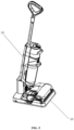
    • FIG. 1 is a schematic structural diagram of a docking station provided by some embodiments of the present disclosure, where the docking station is in a connected state;
    • FIG. 2 is a schematic structural diagram of a docking station provided by some embodiments of the present disclosure, where the docking station is in a connected state;
    • FIG. 3 is a schematic structural diagram of a docking station provided by some embodiments of the present disclosure, where the docking station is in a demounted state;
    • FIG. 4 is a schematic structural diagram of a docking station provided by some embodiments of the present disclosure, where the docking station is in a demounted state;
    • FIG. 5 is a schematic structural diagram of a cleaning system provided by some embodiments of the present disclosure, where a cleaning device is supported by a docking station;
    • FIG. 6 is a schematic structural diagram of a cleaning system provided by some embodiments of the present disclosure, where a cleaning device is separated from a docking station;
    • FIG. 7 is a schematic structural diagram of a docking station provided by some embodiments of the present disclosure, where the docking station is in a connected state;
    • FIG. 8 is a schematic enlarged diagram of a region M in FIG. 7;
    • FIG. 9 is a sectional view of a part of the region M shown in FIG. 8;
    • FIG. 10 is a schematic enlarged diagram of a part of FIG. 9;
    • FIG. 11 is a schematic diagram of a partial structure of a device body of a cleaning device provided by some embodiments of the present disclosure; and
    • FIG. 12 is a schematic structural diagram of a section on which a first charging/communication interface is in plug-in connection with a second charging/communication interface provided by some embodiments of the present disclosure.
    DETAILED DESCRIPTION
  • To make the objectives, technical solutions and advantages of the present disclosure clearer, the present disclosure is further described in detail below with reference to the accompanying drawings. Apparently, the described embodiments are merely some rather than all of the embodiments of the present disclosure. All other embodiments obtained by those of ordinary skill in the art based on the embodiments of the present disclosure without creative efforts shall fall within the scope of protection of the present disclosure.
  • It should further be noted that, the terms "comprise", "include" and any other variants thereof are intended to cover non-exclusive inclusion, so that a commodity or an apparatus that includes a series of elements includes not only these elements but also other elements that are not expressly listed, or also includes elements inherent to this commodity or apparatus. Without more restrictions, an element defined by the phrase "including a ..." does not exclude the presence of another same element in a commodity or an apparatus that includes the element.
  • In the art, a cleaning device, for example, a floor scrubber, generally includes a device body and a cleaning base body. The cleaning device is generally provided with a water recycling tank, for example, a waste water tank and a cleaning liquid tank (e.g., a clean water tank), and a main fan used for suction. The cleaning base body includes one, two, or more cleaning brushrolls used for scrubbing. Cleaning liquid, for example, water, is dispensed onto the cleaning brushroll having fluff and/or onto a surface to be cleaned through a built-in water pipe. The cleaning brushroll rotates at a high speed to mop the surface to be cleaned. At the same time, a negative pressure is formed in a device air duct of the cleaning device by the main fan, enabling that waste water (that may include solid garbage) on the surface to be cleaned is sucked in through a waste water suction opening of the cleaning device and is pumped into the waste water tank. The foregoing waste water recycling path forms a part of the device air duct of the cleaning device.
  • After usage, the cleaning device is generally placed back onto a docking station to be supported by the docking station. Self-cleaning of the device, for example, washing of the cleaning brushroll and/or drying of the cleaning brushroll, may be performed on the docking station. A charging operation may also be performed on the docking station. In the related art, the docking station is usually of an integrated structure that has a relatively large size. In this case, a relatively large package needs to be equipped. In addition, an accommodation groove on a base of the docking station is configured to accommodate the cleaning base body of the cleaning device. The cleaning brushroll of the cleaning base body needs to be washed in the accommodation groove. Dirt exists in the accommodation groove, particularly, in a brushroll groove corresponding to the cleaning brushroll. The integrated structure of the docking station is not conductive to washing of the accommodation groove, particularly, the brushroll groove. Specifically, electronic components such as a charging wire, a circuit board and a fan exist in the docking station. Therefore, when the docking station of the integrated structure is washed, the electronic components have the risk of wading. In addition, because the size of the integrated structure is too large, the integrated structure is not conductive to cleaning.
  • The present disclosure provides a docking station. The docking station is configured to support a cleaning device and includes a station body and a detachable tray. The station body includes a base tray and a support base disposed on the base tray. The support base is configured to support a device body of the cleaning device. The detachable tray is configured to be detachably connected with the base tray. The detachable tray is connected to the base tray to form an accommodation groove. The accommodation groove is configured to accommodate a cleaning base body of the cleaning device. The detachable tray is provided with a brushroll groove configured to accommodate a cleaning brushroll of the cleaning base body. The detachable tray further includes a water blocking rib(s) disposed on one side or two sides of the brushroll groove.
  • In the present disclosure, the docking station includes the station body and the detachable tray. The detachable tray is detachably connected to the base tray of the station body, which can reduce a package size of the docking station. In addition, the detachable tray may be demounted and separated from the station body, facilitating a user to clean the detachable tray. The detachable tray is provided with the brushroll groove and the water blocking ribs disposed on the two sides of the brushroll groove, so that when the cleaning device performs, on the docking station, an operation of washing the cleaning brushroll, cleaning liquid can be kept in the brushroll groove as much as possible, thereby avoiding the cleaning liquid to be spilled into another portion of the accommodation groove.
  • The followings describe optional embodiments of the present disclosure with reference to the accompanying drawings.
  • FIG. 1 is a schematic structural diagram of a docking station provided by some embodiments of the present disclosure, where the docking station is in a connected state. FIG. 2 is a schematic structural diagram of a docking station provided by some embodiments of the present disclosure, where the docking station is in a connected state. The docking station shown in FIG. 2 and the docking station shown in FIG. 1 are taken from different viewing angles. FIG. 3 is a schematic structural diagram of a docking station provided by some embodiments of the present disclosure, where the docking station is in a demounted state. FIG. 4 is a schematic structural diagram of a docking station provided by some embodiments of the present disclosure, where the docking station is in a demounted state. The docking station shown in FIG. 4 and the docking station shown in FIG. 3 are taken from different viewing angles. Some embodiments of the present disclosure provide a docking station 10. The docking station 10 is configured to support a cleaning device. For example, the cleaning device is a floor scrubber. After finishing a cleaning operation, the floor scrubber may be placed back onto the docking station 10 for supporting. Various operations such as charging, washing a cleaning brushroll, and/or drying the cleaning brushroll may be performed on the docking station.
  • As shown in FIG. 1 to FIG. 4, the docking station 10 includes a station body 13 and a detachable tray 111 that are detachably connected with each other. Specifically, the station body 13 includes a base tray 112 and a support base 12. The support base 12 is disposed on the base tray 112. For example, the support base 12 extends from a surface of the base tray 112 along a direction substantially perpendicular to the base tray 112 and away from the base tray 112. The support base 12 and the base tray 112 may be of an integrated structure or may be of separated structures. The support base 12 is configured to support a device body of the cleaning device. When the cleaning device is placed on the docking station 10, the support base 12 supports the device body of the cleaning device. The detachable tray 111 is configured to be detachably connected with the base tray 112, and the detachable tray 111 and the base tray 112 jointly form a base 11 of the docking station 10.
  • When the detachable tray 111 is connected to the base tray 112 to form the complete base 11, the base 11 is provided with an accommodation groove 14. The accommodation groove 14 is configured to accommodate a cleaning base body of the cleaning device. When the cleaning device is placed on the docking station 10, the base 11 supports and accommodates the cleaning base body of the cleaning device. The cleaning base body is at least partially accommodated in the accommodation groove 14 to facilitate a self-washing operation, on the docking station 10, of the cleaning brushroll on the cleaning base body, thereby removing stains on the cleaning brushroll.
  • The detachable tray 111 is provided with a brushroll groove 1111 configured to accommodate the cleaning brushroll of the cleaning base body. The detachable tray further includes water blocking ribs 1112 disposed on two sides of the brushroll groove. For example, the number of the brushroll groove 1111 is one or more and is matched with the number of the cleaning brushroll of the cleaning device. In other embodiments, one brushroll groove 1111 may correspond to one or more cleaning brushrolls. As shown in FIG. 1 to FIG. 3, there are, for example, two brushroll grooves 1111; and the two brushroll grooves 1111 are disposed in parallel. There are, for example, also two water blocking ribs 1112 that are disposed on two sides of the brushroll grooves 1111 respectively. The cleaning brushroll may perform a washing operation in the brushroll groove 1111 by using cleaning liquid. The water blocking rib 1112 is configured to block the cleaning liquid from spilling outwards from the brushroll groove 1111 when the cleaning brushroll performs a self-washing operation.
  • In the present disclosure, the detachable tray 111 is detachably connected to the base tray 112 of the station body 13. After being demounted, the detachable tray 111 and the base tray 112 can be placed in a more flexible manner, so that space can be utilized more properly. Therefore, the design flexibility of a package is higher. For example, a relatively small package may be used for the docking station 10 that is in the demounted state, thereby reducing package costs. In addition, for the brushroll groove in which dirt is easy to accumulate, because the detachable tray 111 may be demounted and separated from the station body 13, a user may wash the detachable tray 111 after the detachable tray 111 is demounted. This facilitates washing.
  • In some embodiments, as shown in FIG. 1 to FIG. 4, the base tray 112 includes a first fixing clamp piece 1121. The first fixing clamp piece 1121 extends from a side wall, namely, a connecting side wall, of the base tray 112 along a direction away from the support base 12. The connecting side wall is, for example, a side wall of the base tray 112 away from the support base 12. The detachable tray 111 includes a second fixing clamp piece 1113. The second fixing clamp piece 1113 is configured to be detachably matched and clamped with the first fixing clamp piece 1121, thereby enabling the detachable tray 111 to be connected to the base tray 112. With the above structure, the detachable tray 111 may be conveniently mounted to the base tray 112 or demounted from the base tray 112.
  • In some embodiments, as shown in FIG. 1 to FIG. 4, there are a plurality of first fixing clamp pieces 1121. The plurality of first fixing clamp pieces 1121 are uniformly disposed along a connecting side wall of the base tray 112, for example, the connecting side wall is a side wall of the base tray 112 away from the support base 12. There are a plurality of second fixing clamp pieces 1113. The plurality of second fixing clamp pieces 1113 are in a one-to-one correspondence with the plurality of first fixing clamp pieces 1121. Two or more pairs of the first fixing clamp pieces 1121 and the second fixing clamp pieces 1113 that are matched with each other can make the detachable tray 111 and the base tray 112 be connected firmly. After the detachable tray 111 and the base tray 112 are connected, their positions are relatively fixed.
  • In some embodiments, one of the first fixing clamp piece 1121 and the second fixing clamp piece 1113 includes a T-shaped clamping groove; the other one of the first fixing clamp piece 1121 and the second fixing clamp piece 1113 includes a T-shaped insert; and the T-shaped clamping groove and the T-shaped insert are configured to be matched and clamped with each other. In the present disclosure, the T-shaped clamping groove is a clamping groove having a specific structure. A section, in a plane perpendicular to a first direction, of the clamping groove is T-shaped, as shown in FIG. 3 and FIG. 4. For example, the first direction is a vertical direction Y. For example, the plane perpendicular to the first direction is a horizontal plane. In the present disclosure, the T-shaped insert is an insert having a specific structure. A section, in a plane perpendicular to a first direction, of the insert is T-shaped, as shown in FIG. 3 and FIG. 4. For example, the first direction is a vertical direction Y. For example, the plane perpendicular to the first direction is a horizontal plane.
  • In some embodiments, as shown in FIG. 3 and FIG. 4, the first fixing clamp piece 1121 includes a T-shaped clamping groove; and the second fixing clamp piece includes a T-shaped insert. In a process of connecting the detachable tray 111 to the base tray 112, the detachable tray 111 may be moved towards the base tray 112 along the first direction Y until the detachable tray 111 and the base tray 112 are connected together. For example, first, the station body 13 is placed on an operating surface, for example, a horizontal floor; then, the detachable tray 111 is moved towards the horizontal floor along the vertical direction from top to bottom; and the second fixing clamp piece 1113 is aligned and in plug-in connection with the corresponding first fixing clamp piece 1121. In a process of demounting the detachable tray 111 from the base tray 112, the detachable tray 111 may be moved away from the base tray 112 along the first direction Y. For example, when the docking station 10 is placed on an operating surface, for example, a horizontal floor, the detachable tray 111 is moved away from the base tray 112 along the vertical direction from bottom to top.
  • After the first fixing clamp piece 1121 and the second fixing clamp piece 1113 that have the specific structures are matched and in plug-in connection with each other, the base tray 112 and the detachable tray 111 can be prevented from moving relative to each other in a horizontal direction. This can further make the base tray 112 and the detachable tray 111 be firmly connected with each other.
  • In some embodiments, the base tray 112 includes a first positioning clamp piece 1122. The first positioning clamp piece 1122 is disposed on the connecting side wall of the base tray 112, for example, the side wall of the base tray 112 away from the support base 12. The detachable tray 111 further includes a second positioning clamp piece 1114 configured to be clamped with the first positioning clamp piece 1122, thereby connecting the detachable tray 111 and the base tray 112 in position. In a process of aligning and plug-in connection of the first fixing clamp piece 1121 and the second fixing clamp piece 1113, the first positioning clamp piece 1122 and the second positioning clamp piece 1114 are matched and clamped with each other, which indicates that the first fixing clamp piece 1121 and the second fixing clamp piece 1113 are connected in a plug-in manner in place, and that the base tray 112 and the detachable tray 111 are firmly connected together.
  • In an embodiment, the first positioning clamp piece 1122 is disposed on at least one of two ends of the connecting side wall of the base tray. For example, as shown in FIG. 1 to FIG. 4, the first positioning clamp piece 1122 is disposed on each of the two ends of the side wall, away from the support base, of the base tray.
  • In some embodiments, one of the first positioning clamp piece 1122 and the second positioning clamp piece 1114 includes a positioning clamp hole; and the other one of the first positioning clamp piece 1122 and the second positioning clamp piece 1114 includes a positioning snap. For example, as shown in FIG. 1 to FIG. 4, the first positioning clamp piece 1122 includes the positioning clamp hole, and the second positioning clamp piece 1114 includes the positioning snap. When the first positioning clamp piece 1122 and the second positioning clamp piece 1114 are matched and in a snap-fit connection, it indicates that the first fixing clamp piece 1121 and the second fixing clamp piece 1113 are connected to each other in a plug-in manner in place, and that the base tray 112 and the detachable tray 111 are connected in place to form the base 11.
  • In some embodiments, the detachable tray 111 includes a blocking arm 1115 that is disposed on at least one end of the brushroll groove 1111 and configured to prevent the cleaning brushroll of the cleaning device from slipping. After usage, the cleaning device is generally placed back onto the docking station to be supported by the docking station. The cleaning brushroll can be washed on the docking station. The cleaning brushroll is at least partially accommodated in the brushroll groove 1111. The self-washing operation of the cleaning brushroll is mainly performed in the brushroll groove. In the washing process, the cleaning brushroll needs to rotate. The blocking arm 1115 is disposed at the end of the brushroll groove and thus can prevent the cleaning brushroll from slipping.
  • In some embodiments, as shown in FIG. 1 to FIG. 4, the blocking arm 1115 has a greater height than a side wall of the accommodation groove 14.
  • FIG. 5 is a schematic structural diagram of a cleaning system provided by some embodiments of the present disclosure, where a cleaning device is supported by a docking station. FIG. 6 is a schematic structural diagram of a cleaning system provided by some embodiments of the present disclosure, where a cleaning device is separated from a docking station.
  • Some embodiments of the present disclosure further provide a cleaning device 20, for example, a floor scrubber. The cleaning device 20 is matched with the docking station 10. As shown in FIG. 5 and FIG. 6, the cleaning device 20 includes a cleaning base body 21, a device body 22 and a handle assembly 23. The device body 22 is disposed above the cleaning base body 21, and is movably connected to the cleaning base body 21, for example, pivotally connected to the cleaning base body 21. The handle assembly 23 is connected to an end of the device body 22 away from the cleaning base body 21 and is used for being grasped by a user during an operation. The user grasps the handle assembly 23, thereby controlling the cleaning base body 21 to execute a cleaning task on a surface to be cleaned, for example, on a floor.
  • In some embodiments, the device body 22 extends lengthwise. The handle assembly 23 is connected to an upper end of the device body 22. The cleaning base body 21 is connected to a lower end of the device body 22. The device body 22 is pivotally connected to the cleaning base body 21, enabling the handle assembly 23 and the device body 22 to rotate relative to the cleaning base body 21, thereby changing an operating angle and flexibly adjusting a washing posture. The cleaning base body 21 includes a cleaning component, for example, the cleaning brushroll 211, disposed at the bottom of the cleaning base body 21. Specifically, for example, the number of the cleaning brushroll 211 is one or more, for example, two or three. The cleaning brushroll 211 can rotate at a high speed to mop a floor.
  • In some embodiments, as shown in FIG. 5 and FIG. 6, the cleaning device 20, for example, a floor scrubber, further includes a clean water tank 26 and a waste water tank 25, both of which are, for example, disposed on the device body 22. The clean water tank 26 accommodates cleaning liquid, for example, cleaning water, and may provide the cleaning water for the cleaning brushroll 211 through a clean water pipeline to wet a surface of the cleaning brushroll 211, thereby enabling the cleaning brushroll 211 to perform wet cleaning on the surface to be cleaned. The waste water tank 25 is configured to accommodate recycled waste water. When the cleaning brushroll 211 performs wet cleaning, waste water is generated on the surface that is cleaned. The waste water may be recycled into the waste water tank 25 through a waste water recycling pipeline.
  • In some embodiments, as shown in FIG. 5 and FIG. 6, after finishing a cleaning operation, the cleaning device 20 is generally placed on the docking station 10. The docking station 10 supports and fixes the cleaning device 20. With reference to FIG. 1 to FIG. 6, in some embodiments, an end of the support base 12 away from the base tray 112 is provided with a support groove 121. The support groove 121 is configured to accommodate a part of the device body 22 of the cleaning device 20 to support the device body 22. For example, the support groove 121 is configured to accommodate an end of the device body 22 of the cleaning device 20 away from the handle assembly 23. When the cleaning device 20 is placed on the docking station 10 after finishing the cleaning operation, the support groove 121 supports the device body 22, the accommodation groove on the base 11 accommodates and supports the cleaning base body 21 of the cleaning device 20, and the cleaning brushroll 211 on the cleaning base body 21 is accommodated in the brushroll groove 1111.
  • When the cleaning device 20 is supported by the docking station 10, the cleaning device 20 may further perform maintenance operations such as charging, self-cleaning and drying. In some embodiments, as shown in FIG. 1 to FIG. 6, the docking station 10 may include a first charging/communication interface; the cleaning device 20 may include a second charging/communication interface; and the first charging/communication interface is matched and connected with the second charging/communication interface, thereby implementing a charging/communication function between the cleaning device 20 and the docking station 10. The charging/communication function herein is at least one of a charging function or a communication function. In the present disclosure, the character "/" denotes and/or.
  • In some embodiments, the first charging/communication interface includes at least one first charging/communication terminal. The at least one first charging/communication terminal is a female terminal or a male terminal. For example, when the first charging/communication terminal is the female terminal, the second charging/communication interface on the cleaning device 20 is correspondingly provided with a matched male terminal; or when the first charging/communication terminal is the male terminal, the second charging/communication interface on the cleaning device 20 is correspondingly provided with a matched female terminal. When the male terminal and the female terminal that are matched with each other are disposed on the docking station 10 and the cleaning device 20 respectively, the cleaning device 20 is enabled to have a good electrical path when performing a maintenance operation. In some embodiments, there may be two or more first charging/communication terminals. The plurality of first charging/communication terminals may be arranged regularly. All the first charging/communication terminals may be terminals of the same type, for example, charging terminals, communication terminals, or time division multiplexing composite terminals of charging terminals and communication terminals. Alternatively, some of the first charging/communication terminals are charging terminals, and the other first charging/communication terminals are communication terminals.
  • With reference to FIG. 1 to FIG. 6, by taking that both the first charging/communication interface and the second charging/communication interface are charging interfaces as an example, the first charging interface 122 is disposed in the support groove 121, and the first charging interface 122 is configured to be matched and connected with the second charging interface on the device body 22, thereby charging the device body 22.
  • In the related art, the cleaning device may be placed back onto the docking station for charging. However, a charging terminal in a charging interface on the docking station is usually exposed outside, and thus is easily affected by moisture in an external environment. As a result, a charging path becomes faulty. In addition, because the charging terminal is exposed outside, in a case that the user spills water onto the charging terminal by accident during usage, an operating circuit is prone to short circuit if accumulated water is not removed timely. As a result, the device is damaged.
  • To resolve this problem, some embodiments of the present disclosure further provide a docking station. The docking station is configured to support a cleaning device, and charge the cleaning device and/or communicate with the cleaning device. The docking station includes: a base configured to support a cleaning base body of the cleaning device, and a support base disposed on the base and configured to support a device body of the cleaning device. The support base includes a first charging/communication interface. The first charging/communication interface includes: a first charging holder provided with a cavity, a female/male terminal disposed in the cavity and configured to be in plug-in connection with a male/female terminal on the cleaning device, and a water-proof layer, for example, a water-proof flexible plastic layer coating at least a part of the first charging holder to protect the female/male terminal. In the present disclosure, the water-proof flexible plastic layer is used to protect a female charging terminal in the cavity, thereby protecting the female charging terminal from being affected by external moisture and preventing the female charging terminal from being in contact with electrically conductive liquid.
  • The following embodiment is described by taking that the first charging/communication interface is a first charging interface, the second charging/communication interface is a second charging interface, the female/male terminal is a female charging terminal, and the male/female terminal is a male charging terminal as an example.
  • FIG. 7 is a schematic structural diagram of a docking station provided by some embodiments of the present disclosure, where the docking station is in a connected state. The docking station shown in FIG. 7 and the docking stations shown in FIG. 1 and FIG. 2 are taken from different viewing angles. FIG. 8 is a schematic enlarged diagram of a region M in FIG. 7. FIG. 9 is a sectional view of a part of the region M shown in FIG. 8. FIG. 10 is a schematic enlarged diagram of a part of FIG. 9.
  • With reference to FIG. 1 to FIG. 10, some embodiments of the present disclosure provide a docking station 10. The docking station 10 supports the cleaning device 20 and charges the cleaning device 20. The docking station 10 includes a base 11 and a support base 12. The base 11, for example, is provided with an accommodation groove 14. The accommodation groove 14 is configured to accommodate a cleaning base body 21 of the cleaning device 20. The support base 12 is disposed on the base 11 and is configured to support a device body 22 of the cleaning device 20. The support base 12, for example, extends from an upper surface of the base 11 along a direction substantially perpendicular to the base 11 and away from the base 11.
  • As shown in FIG. 1 to FIG. 10, the support base 12 includes a first charging interface 122 that is configured to be connected to a second charging interface on the cleaning device 20, thereby charging the cleaning device 20. The first charging interface 122 includes a first charging holder 1221, a female charging terminal 1222 and a water-proof flexible plastic layer 1223. For example, the first charging interface 122 is disposed in a support groove 121 of the support base 12. The first charging interface 122 extends from a bottom of the support groove 121 along a direction away from the base 11. The second charging interface on the cleaning device 20, for example, is at an end of the device body 22 away from the handle assembly 23. When the cleaning device 20 is placed back onto the docking station 10 for supporting, the support base 12 supports the device body 22, the device body 22 is partially accommodated in the support groove 121, and the first charging interface 122 is connected with the second charging interface on the cleaning device 20, thereby performing a charging operation.
  • The first charging holder 1221 is provided with a cavity 12211. The female charging terminal 1222 is disposed in the cavity 12211 and is configured to be in plug-in connection with a male charging terminal of the second charging interface on the cleaning device 20, thereby charging the cleaning device 20. The water-proof flexible plastic layer 1223 coats at least a part of the first charging holder 1221 to protect the female charging terminal 1222, thereby avoiding the following problem to ensure charging performance of the first charging interface 122: external moisture or liquid is in contact with the female charging terminal 1222 as the female charging terminal 1222 is directly exposed outside.
  • In some embodiments, as shown in FIG. 1 to FIG. 10, the cavity 12211 is provided with a cavity inlet 122111. The cavity inlet 122111 is, for example, disposed at an end of the cavity 12211 away from the base 11, and configured to guide the male charging terminal into the cavity 12211 for plug-in connection with the female charging terminal 1222. The cavity inlet 122111 is, for example, a structure that gradually broadens in a direction away from the cavity, so that the male charging terminal can be conveniently guided into the cavity 12211.
  • In some embodiments, the water-proof flexible plastic layer 1223 includes a water-proof flexible plastic head 12231. The water-proof flexible plastic head 12231 is disposed on a side of the cavity 12211 away from the base 11. The water-proof flexible plastic head 12231 is configured to be switchable between an open state and a closed state.
  • When the cleaning device 20 is supported by the docking station 10, the male charging terminal presses the water-proof flexible plastic head 12231 to make the water-proof flexible plastic head 12231 be in the open state, and the male charging terminal passes through the water-proof flexible plastic head 12231 and enters the cavity 12211 to be in plug-in connection with the female charging terminal 1222. When the cleaning device 20 is not supported by the docking station 10, the water-proof flexible plastic head 12231 is in the closed state to protect the female charging terminal 1222 in the cavity 12211.
  • The water-proof flexible plastic head 12231 is made of an elastic material and, for example, is provided with a notch, such as a cross-shaped notch. Under the action of no external force, the water-proof flexible plastic head is in the closed state. When the cleaning device 20 is placed on the docking station 10 and supported by the docking station 10, the male charging terminal of the cleaning device 20 is abutted against and exerts pressure on the water-proof flexible plastic head 12231, enabling the water-proof flexible plastic head 12231 to be in the open state. The male charging terminal may pass through the water-proof flexible plastic head 12231 to enter the cavity 12211 and be in plug-in connection with the female charging terminal 1222, thereby forming an electrical path for charging the cleaning device 20. In this case, a notch wall of the water-proof flexible plastic head 12231 is tightly attached to a side wall of the male charging terminal, which prevents intrusion of external liquid such as water, and can also implement sealing and water-proof functions in a charging process. It may be conceivable that the water-proof flexible plastic layer may also be made of a material that has similar properties as the flexible plastic, and the similar properties refer to being water proof and provided with elasticity.
  • In some embodiments, there may be one or more female charging terminals 1222. For example, the plurality of female charging terminals 1222 may be arranged regularly. As shown in FIG. 7 to FIG. 10, four female charging terminals 1222 are uniformly arranged in a row. In other embodiments, the plurality of female charging terminals 1222 may also be arranged in two or more rows. There may also be one or more cavities 12211 and one or more water-proof flexible plastic heads 12231. The cavities 12211 and the water-proof flexible plastic heads 12231 are in one-to-one correspondence with the female charging terminals 1222 respectively.
  • In some embodiments, as shown in FIG. 1 to FIG. 10, the first charging interface 122 further includes a guide pillar 1224 that is disposed on the first charging holder 1221. For example, the guide pillar 1224 extends from the first charging holder 1221 towards a direction away from the base 11. The guide pillar 1224 is configured to be inserted into a guide hole of the cleaning device 20, enabling the female charging terminal 1222 and the male charging terminal to be aligned with each other, thereby facilitating accurate connecting between the female charging terminal 1222 and the male charging terminal.
  • In some embodiments, as shown in FIG. 7 to FIG. 10, the first charging holder 1221 includes a charging holder body 12212 and a protruding portion 12213. The protruding portion 12213 is disposed on the charging holder body 12212. The cavity 12211 extends from an interior of the charging holder body 12212 into the protruding portion 12213. The guide pillar 1224 is also disposed on the charging holder body 12212 and is spaced from the protruding portion 12213. In some embodiments, the number of the guide pillar 1224 is one or more, for example, two. For example, the two guide pillars 1224 are disposed on two sides of the protruding portion 12213 respectively, and correspond to two guide holes of the cleaning device 20 respectively. Limitations to shapes of the guide pillar and the guide hole are not described. Only the following is indicated: the guide pillar and the guide hole are of a convex structure and a concave structure respectively, and are matched with each other. In some embodiments, the guide pillar may be a protrusion of any shape, such as a cylinder, a circular cone or a frustum. Accordingly, the guide hole is designed, based on the shape of the guide pillar, to be a groove having a matched shape.
  • In some embodiments, as shown in FIG. 7 to FIG. 10, the guide pillar 1224 is parallel to the cavity 12211. The guide pillar 1224 has a greater length than the protruding portion 12213. For example, in the extending direction of the guide pillar 1224, an end of the guide pillar 1224 away from the first charging holder 1221 is farther away from the base 11 than an end of the water-proof flexible plastic head 12231 away from the first charging holder 1221. Based on such arrangements, in a process of connecting the first charging interface 122 of the docking station 10 with the second charging interface of the cleaning device 20 for charging, before the male charging terminal is in contact with the female charging terminal 1222, the guide pillar 1224 may be inserted into the guide hole of the cleaning device 20 for guiding of alignment, enabling the female charging terminal 1222 and the male charging terminal to be aligned with each other. This avoids damage to a charging connector caused by misplacement of the charging terminals, repeated trials, or the like.
  • FIG. 11 is a schematic diagram of a partial structure of a device body of a cleaning device provided by some embodiments of the present disclosure. The partial structure is a partial structure of the cleaning device 20 shown in FIG. 6 which is a bottom view. FIG. 12 is a schematic structural diagram of a section on which a first charging/communication interface is in plug-in connection with a second charging/communication interface provided by some embodiments of the present disclosure.
  • As shown in FIG. 1 to FIG. 12, the present disclosure provides a cleaning device 20. The cleaning device 20 is configured to be supported by the docking station 10 for charging, and includes a cleaning base body 21 and a device body 22. The device body 22 is disposed above the cleaning base body 21, and is movably connected to the cleaning base body 21, for example, pivotally connected to the cleaning base body 21. The cleaning base body 21 includes a cleaning brushroll 211. The cleaning device 20 may further include a handle assembly 23 that is connected to an end of the device body 22 away from the cleaning base body 21 and is used for being grasped by a user during an operation.
  • The device body 22 includes a second charging interface 221. The second charging interface 221 is, for example, disposed at an end of the device body 22 away from the handle assembly 23. The second charging interface 221 includes a second charging holder 2211 and a male charging terminal 2212. The male charging terminal 2212 is disposed on the second charging holder 2211 and is configured to be in plug-in connection with the female charging terminal 1222 on the docking station 10, thereby forming a charging path for charging the cleaning device 20.
  • In some embodiments, the second charging holder 2211 is provided with a recess portion 22111; the male charging terminal 2212 is at least partially disposed in the recess portion 22111; and the male charging terminal 2212 extends from a bottom surface of the recess portion 22111 towards a direction away from the device body 22. When the cleaning device 20 is placed on the docking station 10, the protruding portion 12213 of the first charging holder 1221 is at least partially inserted into the recess portion 22111. The shape of the protruding portion 12213 is matched with that of the recess portion 22111, enabling the first charging interface 122 and the second charging interface 221 to be firmly connected with each other.
  • In some embodiments, the second charging holder 2211 is provided with a guide hole 22112, and the guide hole 22112 is configured to accommodate the guide pillar 1224 of the docking station 10, enabling the male charging terminal 2212 and the female charging terminal 1222 to be aligned with each other. This avoids damage to a charging connecter caused by misplacement of the charging terminals, repeated trials, or the like. In some embodiments, the number of the guide hole 22112 corresponds to that of the guide pillar 1224, and may be one or more, for example, two. For example, the two guide holes are disposed on two sides of the recess portion 22111 respectively.
  • In some embodiments, the second charging interface 221 further includes a reset spring 2213. The reset spring 2213 is disposed in the guide hole 22112 and is configured to push against the guide pillar 1224, thereby enabling the guide pillar 1224 to trend to be separated from the guide hole 22112. Due to the arrangement of the reset spring, the following problem can be avoided: it is difficult to separate the second charging interface 221 from the first charging interface 122. Specifically, the following problem is prevented: the second charging interface 221 is clamped tightly with the first charging interface 122, and thus it is difficult to separate the cleaning device 20 from the docking station 10. When the cleaning device 20 is placed on the docking station 10 for charging, the reset spring is enabled to be in a compressed state under the action of the self-weight of the cleaning device 20, and at the same time, the second charging interface 221 is enabled to be in plug-in connection with the first charging interface 122 in place, so that poor connection between charging terminals can be avoided. When a user takes the cleaning device 20 down from the docking station, the reset spring may provide a force whose direction is opposite to that of gravity of the cleaning device 20, which can overcome a frictional force generated due to tight clamping between the male charging terminal 2212 and the female charging terminal 1222. Therefore, the user can separate the cleaning device 20 from the docking station 10 by exerting a relatively small force.
  • In some embodiments, an end of the male charging terminal 2212 away from the second charging holder 2211 is of a structure that tapers in a direction away from the second charging holder 2211, facilitating that when the second charging interface 221 is connected with the first charging interface 122, the male charging terminal 2212 presses the notch of the water-proof flexible plastic head 12231, thereby enabling the water-proof flexible plastic head 12231 to be in the open state. Therefore, the male charging terminal 2212 can enter the cavity 12211 to be in plug-in connection with the female charging terminal 1222. When the male charging terminal 2212 does not press the water-proof flexible plastic head 12231, the notch of the water-proof flexible plastic head 12231 is in the closed state, which can prevent external water or moisture from entering the cavity 12211 and protect the female charging terminal 1222. When the male charging terminal 2212 having the foregoing structure presses the water-proof flexible plastic head 12231, the notch of the water-proof flexible plastic head 12231 is opened gradually. In addition, an inner wall of the notch is tightly attached to the male charging terminal 2212. This also implements a water-proof function.
  • In the present disclosure, the water-proof flexible plastic head 12231 that is switchable between the open state and the closed state is used to seal the cavity 12211 inlet that accommodates the female charging terminal 1222; and the water-proof flexible plastic head 12231 is made of an elastic material. Therefore, plug-in connection between the male charging terminal 2212 and the female charging terminal 1222 can be implemented conveniently, and the female charging terminal 1222 can be protected easily.
  • The female/male terminal is a female terminal and includes an elastic interface. The elastic interface is configured to accommodate at least a part of a male terminal. In some embodiments, as shown in FIG. 7 to FIG. 12, the female charging terminal 1222 includes an elastic interface 12221. The elastic interface 12221 is configured to accommodate a part of the male charging terminal 2212, enabling the female charging terminal 1222 to be tightly connected with a corresponding male charging terminal 2212. For example, the elastic interface 12221 includes a plurality of elastic plates, for example, two or more elastic plates. The plurality of elastic plates form an inlet of the elastic interface 12221 in a surrounding manner. The inlet allows the male charging terminal 2212 to be inserted in. The plurality of elastic plates trend to gather together, enabling the male charging terminal 2212 to be clamped tightly by the elastic plates after being inserted into the inlet of the elastic interface 12221. Specifically, the plurality of elastic plates take the shape of a curved arc-shaped surface. The elastic interface 12221 includes a tightening portion and an open portion that are close to the water-proof flexible plastic head 12231 sequentially. The tightening portion is configured to clamp the male charging terminal 2212, enabling the male charging terminal 2212 to be in good electrical contact with the female charging terminal 1222. The opening portion is gradually opened up in the direction towards the water-proof flexible plastic head 12231, for example, takes the shape of a horn mouth. The opening portion is aligned with the cavity inlet 122111, facilitating the male charging terminal 2212 to be inserted into the elastic interface 12221.
  • In some embodiments, as shown in FIG. 8, at least one of a pair of opposite side walls of the support groove 121 of the support base 12 is provided with a guide groove 1211. In some embodiments, each of the pair of side walls is provided with a guide groove 1211. As shown in FIG. 11, at least one of a pair of opposite side walls of the device body 22 of the cleaning device 20 is provided with a guide protrusion 222, for example, each of the pair of opposite side walls is provided with a guide protrusion 222. The guide protrusion 222 is disposed to be matched with the guide groove 1211. When the cleaning device 20 is placed back onto the docking station 10, the guide protrusion 222 is matched with the guide groove 1211. The guide protrusion 222 slides into the guide groove 1211, enabling the device body 22 of the cleaning device 20 to be aligned with the support groove 121 of the support base 12 of the docking station 10. This helps the device body 22 be accurately supported by the support base 12, thereby avoiding misplacement. In some embodiments, the guide groove 1211 extends, on a side wall of the support groove 121, from the top of the side wall towards the bottom of the side wall, and the width of the guide groove 1211 decreases gradually as the guide groove 1211 gradually approaches the bottom of the side wall. Such design facilitates increasing robustness of the support groove 121, into which the device body 22 is placed back, of the support base 12.
  • In some embodiments, the guide groove 1211 is matched with the guide protrusion 222 to form level-1 guided alignment; and the guide pillar 1224 is matched with the guide hole 22112 to form level-2 guided alignment. Due to the two levels of guided alignment, the device body 22 can be accurately placed back into the support groove 121 of the support base 12. This ensures that the male charging terminal 2212 can be in accurate plug-in connection with the female charging terminal 1222.
  • Some embodiments of the present disclosure provide a cleaning system. The cleaning system includes the docking station according to the foregoing embodiments and the cleaning device according to the foregoing embodiments.
  • In an optional embodiment, the detachable tray is provided with a brushroll groove configured to accommodate a cleaning brushroll of the cleaning base body; and the detachable tray further includes water blocking ribs disposed on two sides of the brushroll groove.
  • In an optional embodiment, the base tray includes a first fixing clamp piece. The first fixing clamp piece extends from a side wall of the base tray along a direction away from the support base; and
    the detachable tray includes a second fixing clamp piece. The second fixing clamp piece is configured to be detachably matched and clamped with the first fixing clamp piece, thereby enabling the detachable tray to be connected to the base tray.
  • In an optional embodiment, one of the first fixing clamp piece and the second fixing clamp piece includes a T-shaped clamping groove; the other one of the first fixing clamp piece and the second fixing clamp piece includes a T-shaped insert; and the T-shaped clamping groove and the T-shaped insert are configured to be matched and clamped with each other.
  • In an optional embodiment, the base tray includes a first positioning clamp piece, where the first positioning clamp piece is disposed on the side wall of the base tray; and
    the detachable tray further includes a second positioning clamp piece configured to be clamped with the first positioning clamp piece, thereby connecting the detachable tray and the base tray in position.
  • In an optional embodiment, the first positioning clamp piece is disposed on at least one of two ends of the side wall of the base tray.
  • In an optional embodiment, one of the first positioning clamp piece and the second positioning clamp piece includes a positioning clamp hole; and the other one of the first positioning clamp piece and the second positioning clamp piece includes a positioning snap.
  • In an optional embodiment, the detachable tray includes a blocking arm disposed on at least one end of the brushroll groove.
  • In an optional embodiment, the blocking arm has a greater height than a side wall of the accommodation groove.
  • In an optional embodiment, the docking station is further configured to charge the cleaning device and/or communicate with the cleaning device; and
    an end of the support base away from the base tray is provided with a support groove configured to accommodate a part of the device body of the cleaning device to support the device body; and the support base includes a first charging/communication interface, where the first charging/communication interface is disposed in the support groove.
  • In an optional embodiment, the first charging/communication interface includes:
    • a first charging holder, provided with a cavity;
    • a female/male terminal, disposed in the cavity and configured to be in plug-in connection with a male/female terminal on the cleaning device; and
    • a water-proof layer, coating at least a part of the first charging holder to protect the female/male terminal.
  • In an optional embodiment, the cavity is provided with a cavity inlet configured to guide the male/female terminal into the cavity for plug-in connection with the female/male terminal.
  • In an optional embodiment, the water-proof layer is a water-proof flexible plastic layer and includes:
    • a water-proof flexible plastic head, disposed on a side of the cavity away from the base and configured to be switchable between an open state and a closed state, wherein
    • when the cleaning device is placed back onto the docking station and is in plug-in connection with the first charging/communication interface, the male/female terminal presses the water-proof flexible plastic head to make the water-proof flexible plastic head be in the open state, the male/female terminal passes through the water-proof flexible plastic head and enters the cavity to be in plug-in connection with the female/male terminal; and
    • when the cleaning device is not supported by the docking station, the water-proof flexible plastic head is in the closed state to protect the female/male terminal in the cavity.
  • In an optional embodiment, the first charging/communication interface further includes:
    a guide pillar, disposed on the first charging holder and configured to be inserted into a guide hole of the cleaning device, enabling the female/male terminal and the male/female charging terminal to be aligned with each other.
  • In an optional embodiment, the first charging holder includes:
    • a charging holder body; and
    • a protruding portion, extending from the charging holder body along a direction away from the charging holder body, where
    • the cavity extends into the protruding portion from an interior of the charging holder body; the guide pillar is disposed on the charging holder body and is parallel to the protruding portion; and the guide pillar has a greater length than the protruding portion.
  • In an optional embodiment, the female/male terminal is a female terminal and includes an elastic interface that is configured to accommodate at least a part of a male terminal.
  • Some embodiments of the present disclosure provide a cleaning device. The cleaning device is configured to be supported by a docking station for charging, and includes:
    • a cleaning base body; and
    • a device body, movably connected to the cleaning base body, where
    • the device body includes a second charging/communication interface; and the second charging/communication interface includes:
      • a second charging holder; and
      • a male/female terminal, disposed on the second charging holder and configured to be in plug-in connection with a female/male terminal on the docking station.
  • In an optional embodiment, the second charging holder is provided with a recess portion; the male/female terminal is at least partially disposed in the recess portion; and the male/female terminal extends from a bottom surface of the recess portion towards a direction away from the device body.
  • In an optional embodiment, the second charging holder is provided with a guide hole; and the guide hole is configured to accommodate a guide pillar of the docking station, enabling the male/female terminal and the female/male terminal to be aligned with each other.
  • In an optional embodiment, the second charging/communication interface further includes:
    a reset spring, disposed in the guide hole and configured to push against the guide pillar, thereby enabling the guide pillar to trend to be separated from the guide hole.
  • In an optional embodiment, an end of the male/female terminal away from the second charging holder is of a structure that tapers in a direction away from the second charging holder.
  • Compared with the related art, the foregoing solutions of the embodiments of the present disclosure have at least the following beneficial effects.
  • The docking station includes the station body and the detachable tray. The detachable tray is detachably connected to the base tray of the station body, which can reduce the package size of the docking station. In addition, the detachable tray may be demounted and separated from the station body, facilitating a user to clean the detachable tray.
  • The detachable tray is provided with the brushroll groove and the water blocking ribs disposed on the two sides of the brushroll groove, so that when the cleaning device performs, on the docking station, an operation of washing the cleaning brushroll, cleaning liquid can be kept in the brushroll groove as much as possible, thereby avoiding the cleaning liquid to be spilled into another portion of the accommodation groove.
  • The base tray and the detachable tray are provided with the first fixing clamp piece and the second fixing clamp piece respectively that are matched with each other. The base tray and the detachable tray can be firmly connected to each other through the first fixing clamp piece and the second fixing clamp piece that are matched with each other, thereby forming the base via connecting.
  • The base tray and the detachable tray are provided with the first positioning clamp piece and the second positioning clamp piece respectively that are matched with each other. The base tray and the detachable tray are connected to each other and positioned relative to each other through the first positioning clamp piece and the second positioning clamp piece that are matched with each other, thereby feeding back that the two are mounted in place.
  • The detachable tray includes the blocking arm disposed on at least one end of the brushroll groove, thereby avoiding the cleaning brushroll to be slipped when the cleaning device washes the cleaning brushroll on the docking station.
  • Finally, it should be noted that various embodiments in this description are described in a progressive manner, and each embodiment focuses on the difference from other embodiments. The same or similar parts among the various embodiments can be referred to each other. Since the system or apparatus disclosed in the embodiments corresponds to the method disclosed in the embodiments, the description is relatively simple. For related parts, reference can be made to the description in the method section.
  • Described above are merely exemplary embodiments of the present disclosure, and cannot be construed as a limitation on the scope of the present disclosure. Any equivalent changes and modifications made in accordance with the teachings of the present disclosure still fall within the scope of the present disclosure. Those of skill in the art may readily conceive other embodiments of the present disclosure after considering this description and practicing the content disclosed herein. The present disclosure is intended to cover any variations, uses or adaptive changes of the present disclosure. Such variations, uses or adaptive changes follow the general principle of the present disclosure and include common knowledge or customary technical means in the art which is not disclosed in the present disclosure. This description and the embodiments are merely considered to be exemplary. The scope and spirit of the present disclosure are defined by the claims.

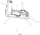
Claims (17)

  1. A docking station, configured to support a cleaning device, comprising:
    a station body, comprising:
    a base tray; and
    a support base, disposed on the base tray and configured to support a device body of the cleaning device; and
    a detachable tray, configured to be detachably connected with the base tray, wherein
    the detachable tray is connected with the base tray to form an accommodation groove; and the accommodation groove is configured to accommodate a cleaning base body of the cleaning device.
  2. The docking station according to claim 1, wherein
    the detachable tray is provided with a brushroll groove configured to accommodate a cleaning brushroll of the cleaning base body; and the detachable tray further comprises water blocking ribs disposed on two sides of the brushroll groove.
  3. The docking station according to claim 1, wherein
    the base tray comprises a first fixing clamp piece, wherein the first fixing clamp piece extends from a side wall of the base tray along a direction away from the support base; and
    the detachable tray comprises a second fixing clamp piece, wherein the second fixing clamp piece is configured to be detachably matched and clamped with the first fixing clamp piece, thereby enabling the detachable tray to be connected to the base tray.
  4. The docking station according to claim 3, wherein
    one of the first fixing clamp piece and the second fixing clamp piece comprises a T-shaped clamping groove; another one of the first fixing clamp piece and the second fixing clamp piece comprises a T-shaped insert; and the T-shaped clamping groove and the T-shaped insert are configured to be matched and clamped with each other.
  5. The docking station according to claim 3 or 4, wherein
    the base tray comprises a first positioning clamp piece, wherein the first positioning clamp piece is disposed on the side wall of the base tray; and
    the detachable tray further comprises a second positioning clamp piece configured to be clamped with the first positioning clamp piece, thereby connecting the detachable tray and the base tray in position.
  6. The docking station according to claim 5, wherein
    the first positioning clamp piece is disposed on at least one of two ends of the side wall of the base tray.
  7. The docking station according to claim 5, wherein
    one of the first positioning clamp piece and the second positioning clamp piece comprises a positioning clamping hole; and another one of the first positioning clamp piece and the second positioning clamp piece comprises a positioning snap.
  8. The docking station according to claim 2, wherein
    the detachable tray comprises a blocking arm disposed on at least one end of the brushroll groove.
  9. The docking station according to claim 8, wherein
    the blocking arm has a greater height than a side wall of the accommodation groove.
  10. The docking station according to any one of claims 1 to 4, wherein
    the docking station is further configured to charge the cleaning device and/or communicate with the cleaning device; and
    an end of the support base away from the base tray is provided with a support groove configured to accommodate a part of the device body of the cleaning device to support the device body; and the support base comprises a first charging/communication interface disposed in the support groove.
  11. The docking station according to claim 10, wherein
    the first charging/communication interface comprises:
    a first charging holder, provided with a cavity;
    a female/male terminal, disposed in the cavity and configured to be in plug-in connection with a male/female terminal on the cleaning device; and
    a water-proof layer, coating at least a part of the first charging holder to protect the female/male terminal.
  12. The docking station according to claim 11, wherein
    the cavity is provided with a cavity inlet configured to guide the male/female terminal into the cavity for plug-in connection with the female/male terminal.
  13. The docking station according to claim 11, wherein
    the water-proof layer is a water-proof flexible plastic layer and comprises:
    a water-proof flexible plastic head, disposed on a side of the cavity away from the base, and configured to be switchable between an open state and a closed state, wherein
    when the cleaning device is placed back onto the docking station and is in plug-in connection with the first charging/communication interface, the male/female terminal presses the water-proof flexible plastic head to make the water-proof flexible plastic head be in the open state, and the male/female terminal passes through the water-proof flexible plastic head and enters the cavity to be in plug-in connection with the female/male terminal; and
    when the cleaning device is not supported by the docking station, the water-proof flexible plastic head is in the closed state to protect the female/male terminal in the cavity.
  14. The docking station according to any one of claims 11 to 13, wherein
    the first charging/communication interface further comprises a guide pillar, disposed on the first charging holder and configured to be inserted into a guide hole of the cleaning device, enabling the female/male terminal and the male/female charging terminal to be aligned with each other.
  15. The docking station according to claim 14, wherein
    the first charging holder comprises:
    a charging holder body; and
    a protruding portion, extending from the charging holder body along a direction away from the charging holder body, wherein
    the cavity extends into the protruding portion from an interior of the charging holder body; the guide pillar is disposed on the charging holder body and is parallel to the protruding portion; and the guide pillar has a greater length than the protruding portion.
  16. The docking station according to any one of claims 11 to 13, wherein
    the female/male terminal is a female terminal, and comprises an elastic interface configured to accommodate at least a part of a male terminal.
  17. A cleaning system, comprising:
    the docking station according to any one of claims 1 to 16; and
    the cleaning device.
EP23844748.6A 2022-07-28 2023-01-03 Pile, cleaning apparatus and cleaning system Pending EP4563056A1 (en)

Applications Claiming Priority (3)

Application Number Priority Date Filing Date Title
CN202210901475.2A CN117502987A (en) 2022-07-28 2022-07-28 Pile body and cleaning system
CN202210901472.9A CN117502986A (en) 2022-07-28 2022-07-28 Pile body and cleaning system
PCT/CN2023/070134 WO2024021529A1 (en) 2022-07-28 2023-01-03 Pile, cleaning apparatus and cleaning system

Publications (1)

Publication Number Publication Date
EP4563056A1 true EP4563056A1 (en) 2025-06-04

Family

ID=89705159

Family Applications (1)

Application Number Title Priority Date Filing Date
EP23844748.6A Pending EP4563056A1 (en) 2022-07-28 2023-01-03 Pile, cleaning apparatus and cleaning system

Country Status (6)

Country Link
US (1) US20250380848A1 (en)
EP (1) EP4563056A1 (en)
JP (1) JP2025515894A (en)
KR (1) KR20250020585A (en)
AU (1) AU2023315478A1 (en)
WO (1) WO2024021529A1 (en)

Family Cites Families (12)

* Cited by examiner, † Cited by third party
Publication number Priority date Publication date Assignee Title
JPS4899892U (en) * 1972-02-29 1973-11-24
JPH0828248B2 (en) * 1992-12-22 1996-03-21 東洋エンジニアリング株式会社 Automatic plug-in connection device
JP3771838B2 (en) * 2001-12-25 2006-04-26 フリー工業株式会社 Flooring unit
US10383499B2 (en) * 2017-08-31 2019-08-20 Irobot Corporation Wet robot docking station
CN208189697U (en) * 2018-03-23 2018-12-04 比亚迪股份有限公司 Single battery, battery modules, power battery and electric car
JP7163422B2 (en) * 2018-06-22 2022-10-31 ビッセル インク. surface cleaner and tray
CN112515545B (en) * 2020-09-11 2024-09-10 深圳银星智能集团股份有限公司 Garbage recycling base station and cleaning system
CN214856396U (en) * 2021-04-28 2021-11-26 北京小米移动软件有限公司 Cleaning chassis
CN215820817U (en) * 2021-07-09 2022-02-15 江苏美的清洁电器股份有限公司 Base of cleaning system
CN113598662A (en) * 2021-07-20 2021-11-05 尚科宁家(中国)科技有限公司 Surface cleaning machine of self-cleaning
CN216569760U (en) * 2021-10-22 2022-05-24 莱克电气股份有限公司 Charging base and cleaning device installed with the charging base
CN114652237B (en) * 2022-03-02 2023-08-01 深圳市杉川机器人有限公司 Cleaning system and replacement method of cleaning unit thereof

Also Published As

Publication number Publication date
AU2023315478A1 (en) 2025-03-13
KR20250020585A (en) 2025-02-11
WO2024021529A9 (en) 2024-04-04
US20250380848A1 (en) 2025-12-18
JP2025515894A (en) 2025-05-20
WO2024021529A1 (en) 2024-02-01

Similar Documents

Publication Publication Date Title
CN215899564U (en) Safety protection mechanism for base station, base station and surface cleaning system
CN215838774U (en) Base station and cleaning robot system
KR102295181B1 (en) Holder for cleaner and cleaner unit
US10405717B2 (en) Cleaner holder
TW201739407A (en) Vacuum cleaner support
WO2017196004A1 (en) Vacuum stand
US20090032071A1 (en) Lid for a semiconductor device processing apparatus and methods for using the same
KR20210086458A (en) Charging apparatus for robot cleaner
CN104213368A (en) Portable laundry treating apparatus
EP4563056A1 (en) Pile, cleaning apparatus and cleaning system
CN218606445U (en) Pile body, cleaning equipment and cleaning system
CN114929080B (en) Charging seat of sweeping robot
CN113287979A (en) Robot of sweeping floor and have its cleaning system
CN217408654U (en) Cleaning device
US20140137347A1 (en) Photomask cleaning device
CN217040005U (en) Surface cleaning apparatus
CN217310129U (en) Base station and cleaning system
CN217218931U (en) Tray and surface cleaning system
CN218500647U (en) Pile body and cleaning system
WO2015088140A1 (en) Cleaning tool-receivable detergent container
CN215016907U (en) Detachable trays, base station equipment and surface cleaning systems
CN117502986A (en) Pile body and cleaning system
KR20180079166A (en) Robot cleaner
CN116236117B (en) Pallet and surface cleaning systems
CN117502987A (en) Pile body and cleaning system

Legal Events

Date Code Title Description
STAA Information on the status of an ep patent application or granted ep patent

Free format text: STATUS: THE INTERNATIONAL PUBLICATION HAS BEEN MADE

PUAI Public reference made under article 153(3) epc to a published international application that has entered the european phase

Free format text: ORIGINAL CODE: 0009012

STAA Information on the status of an ep patent application or granted ep patent

Free format text: STATUS: REQUEST FOR EXAMINATION WAS MADE

17P Request for examination filed

Effective date: 20250217

AK Designated contracting states

Kind code of ref document: A1

Designated state(s): AL AT BE BG CH CY CZ DE DK EE ES FI FR GB GR HR HU IE IS IT LI LT LU LV MC ME MK MT NL NO PL PT RO RS SE SI SK SM TR

DAV Request for validation of the european patent (deleted)
DAX Request for extension of the european patent (deleted)