EP4563015A1 - A manufacturing device for manufacturing tobacco industry rods and a method of manufacturing tobacco industry rods - Google Patents
A manufacturing device for manufacturing tobacco industry rods and a method of manufacturing tobacco industry rods Download PDFInfo
- Publication number
- EP4563015A1 EP4563015A1 EP23212829.8A EP23212829A EP4563015A1 EP 4563015 A1 EP4563015 A1 EP 4563015A1 EP 23212829 A EP23212829 A EP 23212829A EP 4563015 A1 EP4563015 A1 EP 4563015A1
- Authority
- EP
- European Patent Office
- Prior art keywords
- strand
- filling material
- winding roller
- unit
- crimping
- Prior art date
- Legal status (The legal status is an assumption and is not a legal conclusion. Google has not performed a legal analysis and makes no representation as to the accuracy of the status listed.)
- Granted
Links
Images



Classifications
-
- A—HUMAN NECESSITIES
- A24—TOBACCO; CIGARS; CIGARETTES; SIMULATED SMOKING DEVICES; SMOKERS' REQUISITES
- A24D—CIGARS; CIGARETTES; TOBACCO SMOKE FILTERS; MOUTHPIECES OF CIGARS OR CIGARETTES; MANUFACTURE OF TOBACCO SMOKE FILTERS OR MOUTHPIECES
- A24D3/00—Tobacco smoke filters, e.g. filter tips or filtering inserts; Filters specially adapted for simulated smoking devices; Mouthpieces of cigars or cigarettes
- A24D3/02—Manufacture of tobacco smoke filters
- A24D3/0204—Preliminary operations before the filter rod forming process, e.g. crimping, blooming
-
- A—HUMAN NECESSITIES
- A24—TOBACCO; CIGARS; CIGARETTES; SIMULATED SMOKING DEVICES; SMOKERS' REQUISITES
- A24D—CIGARS; CIGARETTES; TOBACCO SMOKE FILTERS; MOUTHPIECES OF CIGARS OR CIGARETTES; MANUFACTURE OF TOBACCO SMOKE FILTERS OR MOUTHPIECES
- A24D3/00—Tobacco smoke filters, e.g. filter tips or filtering inserts; Filters specially adapted for simulated smoking devices; Mouthpieces of cigars or cigarettes
- A24D3/02—Manufacture of tobacco smoke filters
- A24D3/0295—Process control means
Definitions
- the object of the present invention is a manufacturing device for manufacturing tobacco industry rods and a method of manufacturing tobacco industry rods.
- a strand is formed consisting of many narrow strands loosely coupled together, with the material fibers separated from each other.
- This structure has increased filtration properties, as the surface area absorbing smoke particles is increased and the resistance to airflow through the manufactured filter is increased.
- manufacturing such a structure involves an increase in the width of the strand in the free state, and the risk of longitudinal wrinkles is increased, which may reduce the finished filter rods' quality due to variation in resistance values.
- the longitudinal tension of the filling material strand is as low as possible immediately before wrapping the filling material in the wrapper, so that when the finished rod is manufactured, the section of the crimped material strand placed in the rod does not visibly shorten and/or cause wrinkling of the wrapper.
- the longitudinal creases that occur during the manufacturing process cause a change in the parameter relating to the resistance to airflow in the finished rod or in the sections of the rod that are placed in the mouthpieces of smoking articles.
- This parameter is described as the pressure drop of flowing air. It is important that before changing the form of the strand from a flat web to a circular strand, the strand should be acted upon to expand and smooth the material strand, reducing the risk of longitudinal creases and subsequently taking a strand of material with increased width to form a continuous rod.
- WO2013098353A1 and WO2015097127A1 show feeding devices for a manufacturing device for manufacturing rods.
- the feeding devices disclosed therein comprise a crimping device and a compacting device for forming a continuous rod, wherein a strand of the filling material passes directly from the crimping device to the compacting device.
- Document EP3469923A1 shows a manufacturing device in which a strand of the filling material is also directly fed to the compacting device before forming a continuous rod.
- the object of the invention is a manufacturing device for manufacturing tobacco industry rods from a continuous rod manufactured from a crimped strand of a filling material, comprising: a feeding unit for feeding a strand of the filling material, a crimping unit comprising crimping drums for crimping the strand of the filling material in a form of a flat web, a wrapper feeding unit for feeding a tape of a wrapper, a compacting unit for forming the strand of the filling material into a form of a circular strand, a forming unit for forming a continuous rod by wrapping the crimped strand of the filling material into the tape of the wrapper which is transported by a garniture belt and sealed by an adhesive supplied from an adhesive apparatus, a cutting head for cutting the continuous rod into individual rods, wherein the crimped strand of the filling material fed from the crimping unit in the form of a flat web at a first linear speed changes its cross-sectional shape from flat to circular and is
- the first winding roller may have a lateral surface in the shape of a cylinder.
- the first winding roller may have a lateral surface in the shape of a barrel.
- the lateral surface of the first winding roller may have helically shaped elements with opposite directions of spiral inclination, which are arranged symmetrically with respect to a plane of symmetry of the first winding roller and are designed to increase a first width of the filling material strand to a second width of the filling material strand.
- the second linear velocity of the lateral surface of the first winding roller can be greater than the first linear velocity of the fed material strand by a value in the range of 10 to 30%, preferably by a value in the range of 15 to 25%.
- the second linear speed of the lateral surface of the first winding roller can be 20% greater than the first linear speed of the fed strand of the filling material.
- the tensioning unit may further comprise a second winding roller and a tensioning roller, wherein said rollers are positioned relative to the feed path of the material strand such that the filling material strand winds around the first winding roller, the tensioning roller and the second winding roller.
- the tensioning unit may comprise a second drive unit of the second winding roller for imparting a second angular velocity so that the third linear velocity of the lateral surface of the second winding roller is greater than the fourth linear velocity of the garniture belt in the forming unit.
- Another object of the present invention is a method for manufacturing tobacco industry rods from a continuous rod of a crimped filling material strand, comprising the steps of: unwinding a strand of the filling material; crimping the filling material strand, in the form of a flat web, in a crimping unit comprising crimping drums for crimping the filling material strand; feeding the crimped strand of the filling material to a compacting unit; compacting the strand of the filling material in the compacting unit to form a strand with a circular cross-section; feeding and transporting the tape of a wrapper on the garniture belt in the forming unit; moving the strand of the filling material along a feeding path so that the strand of the filling material winds around the first winding roller, and tensioning the strand of the filling material between the crimping unit and the compacting unit by means of a tensioning unit; forming a continuous rod by wrapping the crimped filling material strand in
- the second linear velocity of the lateral surface of the first winding roller can be greater than the first linear velocity of the fed material strand by a value in the range of 10 to 30%, preferably by a value in the range of 15 to 25%.
- the second linear speed of the lateral surface of the first winding roller can be 20% greater than the first linear speed of the fed material strand.
- the method may comprise moving the strand of the filling material such that the strand of the filling material winds around the first winding roller, the tension roller and the second winding roller.
- the method may comprise imparting a second angular velocity to the second winding roller so that the third linear velocity of the lateral surface of the second winding roller is greater than the fourth linear velocity of the garniture belt in the forming unit.
- the method may comprise increasing a first width of the filling material strand at the crimping unit to a second width of the filling material strand at the first winding roller and subsequently decreasing the second width of the filling material strand between the winding roller and the compacting unit.
- the tensioning device ensures that a strand of the filling material is effectively distributed transversely to the material feed direction and that a strand of material is tensioned in the direction along the material strand, thus eliminating the risk of longitudinal creases, which increases the efficiency of the production line.
- the use of a tensioning device ensures that the stresses in the filling material inside the rod are eliminated during rod manufacturing and no deformation of the rod occurs after it is manufactured. Reducing the tension of the expanded strand of the filling material facilitates the longitudinal movement of strands of the filling material relative to each other, so longitudinal stresses in the filling material in the finished product are reduced and a uniform filling material structure is achieved.
- a manufacturing device 1 for the tobacco industry is used for manufacturing rods R from a continuous rod CR of a crimped strand of a filling material 2.
- the device 1 comprises a supplying part 3 and a forming part 4.
- the filling material can be a cellulose-based or other fibrous material of plant origin, or a plastic material.
- the supplying part 3 comprises a supplying unit 5 for feeding a strand of the filling material 2, and a crimping unit 6 with crimping drums 7, 8 for crimping the strand of the filling material 2.
- the strand of the filling material 2 is unwound from a roll 9.
- the crimped strand of the filling material 2 is fed from the crimping unit 6 in the form of a flat web at a first linear speed v1 and is compacted in a compacting unit 10 in the forming part 4.
- a tensioning device 11 is provided in the supplying part 3 to maintain the proper tension of the strand of the filling material 2.
- a forming unit 12 comprising a garniture bar 13 and an adhesive apparatus 14. Additionally, the device 1 comprises a feeding unit 15 for feeding a tape of a wrapper 16.
- the compacting unit 10 is configured to form a strand of the filling material 2' in the form of a circular strand and feed the filling material 2' to the forming unit 12, which forms a continuous rod CR by wrapping the crimped strand of the filling material 2' in the tape of the wrapper 16.
- the forming unit 12 is provided with a garniture belt 17 for transporting the wrapper 16 and the formed continuous rod CR.
- the adhesive apparatus 14 is adapted for feeding adhesive to close the wrapper 16 of the continuous rod CR.
- the continuous rod CR is cut into single rods R by a cutting head 18.
- a tensioning device 11 which comprises a first winding roller 21 is positioned between a crimping unit 6 with the crimping drums 7, 8, and the compacting unit 10.
- the first winding roller 21 is positioned relative to a feed path P of the filling material strand 2 so that the filling material strand 2 winds around the first winding roller 21.
- the tensioning device 11 comprises a first drive unit 19 of the first winding roller 21 for imparting a first angular velocity ⁇ 1 such that the second linear velocity v2 of the lateral surface 24 of the first winding roller 21 is greater than the first linear velocity v1 of the filling material strand 2 being fed.
- a friction force T is generated ( Fig. 2a ), which is directed according to the direction of movement of the filling material strand 2 between the crimping unit 6 and the first winding roller 21.
- the force T constitutes a pulling force for the strand of the filling material 2 and causes the strand of the filling material 2 to be tensioned between the crimping unit 6 and the first winding roller 21, wherein a slippage occurs between the lateral surface 24 of the first winding roller 21 and the strand of the filling material 2.
- the slippage zone is designated as C.
- the second linear velocity v2 of the lateral surface 24 is greater than or equal to the fourth velocity v4 of the garniture belt 17 in the forming unit 12 and therefore is also greater than the velocity of the tape of the wrapper 16.
- a tensioning device 11' is situated between the crimping unit 6 with the crimping drums 7, 8, and the compacting unit 10, which comprises the first winding roller 21, the second winding roller 22 and a tensioning roller 23.
- the rollers 21, 22, 23 are located with respect to the feed path P' of the filling material strand 2 so that the filling material strand 2 winds around the first winding roller 21, the tensioning roller 23, and the second winding roller 22.
- the tensioning roller 23 tensions the filling material strand 2 due to the force of gravity or by using a spring element (not shown).
- the tensioning device 11' comprises a first drive unit 19 of the first winding roller 21 for imparting a first angular velocity ⁇ 1 such that the second linear velocity v2 of the lateral surface 24 of the first winding roller 21 is greater than the first linear velocity v1 of the fed filling material strand 2. Due to the difference in velocity, the filling material strand 2 is tensioned between the crimping unit 6 and the first winding roller 21, wherein there is a slippage between the lateral surface 24 of the first winding roller 21 and the filling material strand 2.
- the tensioning device 11' comprises a second drive unit 20 for imparting a second angular velocity ⁇ 2 to the second winding roller 22 so that the third linear velocity v3 of the lateral surface 27 of the second winding roller 21 is substantially equal to the first linear velocity v1.
- the third linear velocity v3 of the lateral surface 27 is greater than or equal to the fourth linear velocity v4 of the garniture belt 17 in the forming unit 12 and therefore is also greater than the velocity of the tape of the wrapper 16.
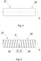
- the first winding roller 21 may have a cylindrical lateral surface 24, as shown in Fig. 4 .
- two spiral-shaped elements 25, 26 with opposite directions of spiral inclination are arranged on the lateral surface 24'. These elements 25, 26 are symmetrically arranged with respect to the plane S, and the angle of inclination ⁇ of the helix with respect to the plane S for both helically shaped elements 25, 26 is the same.
- the elements 25, 26 are arranged along the axis of rotation k.
- the helically shaped elements 25, 26 may be convex above the lateral surface 24'.
- FIG. 6 shows the first winding roller 21" in the third embodiment, in which the lateral surface 24" is in the form of a barrel.
- Fig. 7 two spiral-shaped elements 25', 26' are arranged on the lateral surface 24′′′ of the first winding roller 21'". Similar to the second embodiment, these elements are arranged symmetrically with respect to the plane S, and the angle of inclination ⁇ of the spiral with respect to the plane S for both elements 25, 26 is the same.
- the filling material strand 2 coming out of the crimping unit 6 has a first width W1.
- the width of the filling material strand 2 is greater than the defined width W1.
- the spiral elements 25, 26, 25', 26' are designed to increase the first width W1 of the filling material strand 2 at the crimping unit 6 to the second width W2 of the filling material strand 2 at the first winding roller 21.
- the spiral elements 25, 26, 25', 26' act on the filling material strand 2 so as to provide stretching and smoothing of the filling material strand 2 in a direction transverse to the direction of movement of the filling material strand 2, preventing the formation of longitudinal creases on the material.
- the effect of extending and smoothing the material by stretching in the transverse direction is enhanced if there is slippage between the strand of the filling material 2 and the lateral surface 24, 24', 24", 24′′′ of the first winding roller 21, 21', 21", 21'".
- Stretching the strand of the filling material 2 is necessary because the width of the strand of the filling material 2 increases after crimping in the free state due to the change of material structure, which poses the risk of longitudinal creases.
- the strand of the filling material 2 is unwound from the roll 9.
- the strand of the filling material 2 passes through the unit 6 of the crimping drums 7, 8, where the strand of the filling material 2 in the form of a flat web is crimped.
- the crimped strand of the filling material 2 is fed to the compacting unit 10, where the strand of the filling material 2 is compacted into a strand 2' of a circular cross-section and is fed to the forming unit 12.
- the continuous rod CR is formed by wrapping the crimped strand of the filling material 2 into the tape of the wrapper 16, transported by means of a garniture belt 17, and closed by means of an adhesive fed from the adhesive apparatus 14.
- the tape of the wrapper 16 is fed from the feeding unit 15.
- the continuous rod CR thus formed is fed toward the cutting head 18, which cuts the continuous rod CR into single rods R.
- the strand of the filling material 2 is tensioned by a tensioning device 11, 11', in which the strand of the filling material 2 moves along the feeding path P, P'.
- the feeding path P runs so that the filling material strand 2 winds around the first winding roller 21. Further downstream of the tensioning device 11, the filling material strand 2 reduces its width, moves to the compacting unit 10, and then to the forming unit 12.
- the tensioning device 11 drives the first winding roller 21 with a first angular velocity ⁇ 1 so that the second linear velocity v2 of the lateral surface 24, 24', 24", 24′′′ of the first winding roller 21, 21', 21", 21′′′ is greater than the first linear velocity v1 of the fed strand of material 2.
- the first winding roller 21 and the strand of material 2 are shown in an enlarged view in Fig. 2a .
- the second linear velocity v2 of the lateral surface 24, 24', 24", 24′′′ of the first winding roller 21, 21', 21", 21′′′ may be greater than the first linear velocity v1 of the fed material strand 2 by a value in the range from 10 to 30%, preferably from 15 to 25%, and optimally is greater by 20%.
- the fourth linear speed v4 of the garniture belt 17 and the continuous rod CR is equal to or less than the second linear speed v2, so that the tension of the filling material strand 2' is reduced.
- the tension of the filling material strand 2' on the section BC i.e., between the crimping drums 7, 8 and the first winding roller 21, is greater than that on the preceding section AB upstream of the crimping drums 7, 8.
- the tension in the filling material strand 2' is less than that upstream of the first winding roller 21.
- first cylindrical winding roller 21' with spiral elements 25, 26, 25', 26' or a first barrel-shaped winding roller 21" or a first barrel-shaped winding roller 21′′′ with spiral elements 25, 26, 25', 26' allows for an increase in the first width W1 of the filling material strand 2 at the crimping unit 6 to the second width W2 of the filling material strand 2 at the first winding roller 21. Subsequently, there is a decrease in the width W2 of the filling material strand 2 between the winding roller 21 and the compacting unit 10, as shown in Fig. 2b .
- the feed path P' is arranged such that the filling material strand 2 winds around the first winding roller 21, the tensioning roller 23, and then the second winding roller 22.
- the tensioning roller 23 applies tension to the filling material strand and adjusts its position in response to changes in the length of the filling material strand 2 between the first winding roller 21 and the second winding roller 22 under the influence of gravity or a force exerted by an elastic element. These changes in length may be due to temporary differences in the speed of the crimping unit 6 and the forming unit 12. Further downstream of the tensioning device 11', the filling material strand 2 narrows in width and is moved to the compacting unit 10 and then to the forming unit 12.
- the first winding roller 21 is driven with a first angular velocity ⁇ 1, so that the second linear velocity v2 of the lateral surface 24, 24', 24", 24′′′ of the first winding roller 21, 21', 21", 21′′′ is greater than the first linear velocity v1 of the fed material strand 2.
- the tension of the filling material strand 2 between the crimping unit 6 and the tensioning device 11' is increased.
- the second linear velocity v2 of the lateral surface 24, 24', 24", 24′′′ of the first winding roller 21, 21', 21", 21′′′ may be greater than the first linear velocity v1 of the fed material strand 2 by a value in the range from 10 to 30%, preferably from 15 to 25%, and optimally is greater by 20%.
- the fourth linear speed v4 of the garniture belt 17 and the continuous rod CR is equal to or less than the third linear speed v3 of the filling material strand 2 downstream of the tensioning device 11', so that the tension of the filling material strand 2' is reduced.
- the tension of the filling material strand 2 on the section BC i.e., between the crimping drums 7, 8 and the first winding roller 21, is greater than on the preceding section AB upstream of the crimping drums 7, 8.
- the tension of the filling material strand 2 is essentially unchanged compared to section BC, while on section DE, i.e., between the second winding roller 22 and the inlet to the forming unit 12, the tension in the filling material strand 2' is lower than upstream of the first winding roller 21.
- the transformation of the filling material strand 2 from a flat web to the filling material strand 2' with a circular cross-section is carried out at a low tension, which allows for an even distribution of the filling material 2 in the finished rod R.
Landscapes
- Cigarettes, Filters, And Manufacturing Of Filters (AREA)
Abstract
Description
- The object of the present invention is a manufacturing device for manufacturing tobacco industry rods and a method of manufacturing tobacco industry rods.
- In the tobacco industry, semi-finished and finished products are known, where the filling is formed from a crimped strand of material. To produce the filling, a strand of material is compacted to a cross-section close to a circular shape or inscribed in a circle. A known problem for tobacco industry products manufacturers is forming the filling material strand such as to ensure high-quality rods, with the material strand fed without creases, namely without overlapping adjacent parts of the material strand. This problem is exacerbated because crimping disrupts the structure of the material strand, resulting in many narrow strands with the structure of the input material, between which the material has a relaxed structure. Essentially, a strand is formed consisting of many narrow strands loosely coupled together, with the material fibers separated from each other. This structure has increased filtration properties, as the surface area absorbing smoke particles is increased and the resistance to airflow through the manufactured filter is increased. However, manufacturing such a structure involves an increase in the width of the strand in the free state, and the risk of longitudinal wrinkles is increased, which may reduce the finished filter rods' quality due to variation in resistance values. It is also important that the longitudinal tension of the filling material strand is as low as possible immediately before wrapping the filling material in the wrapper, so that when the finished rod is manufactured, the section of the crimped material strand placed in the rod does not visibly shorten and/or cause wrinkling of the wrapper. As mentioned above, the longitudinal creases that occur during the manufacturing process cause a change in the parameter relating to the resistance to airflow in the finished rod or in the sections of the rod that are placed in the mouthpieces of smoking articles. This parameter is described as the pressure drop of flowing air. It is important that before changing the form of the strand from a flat web to a circular strand, the strand should be acted upon to expand and smooth the material strand, reducing the risk of longitudinal creases and subsequently taking a strand of material with increased width to form a continuous rod. Excessive longitudinal tension on the material strand leads to a reduction in the manufactured product's quality, but the longitudinal tension should be high enough so that no overhang of crimped material is formed in the path of movement of the strand of material downstream the crimping device. There is a need to develop a manufacturing device equipped with a device capable of accepting material of increased width in the crimping process, to wind and tension the filling material strand coming out of the crimping device of increased width, and to reduce the tension of the material immediately before feeding it into the continuous rod forming unit.
-
WO2013098353A1 andWO2015097127A1 show feeding devices for a manufacturing device for manufacturing rods. The feeding devices disclosed therein comprise a crimping device and a compacting device for forming a continuous rod, wherein a strand of the filling material passes directly from the crimping device to the compacting device. DocumentEP3469923A1 shows a manufacturing device in which a strand of the filling material is also directly fed to the compacting device before forming a continuous rod. - It would therefore be desirable to develop a device and method for manufacturing tobacco industry rods in which at least some of the disadvantages described above are at least partially limited.
- The object of the invention is a manufacturing device for manufacturing tobacco industry rods from a continuous rod manufactured from a crimped strand of a filling material, comprising: a feeding unit for feeding a strand of the filling material, a crimping unit comprising crimping drums for crimping the strand of the filling material in a form of a flat web, a wrapper feeding unit for feeding a tape of a wrapper, a compacting unit for forming the strand of the filling material into a form of a circular strand, a forming unit for forming a continuous rod by wrapping the crimped strand of the filling material into the tape of the wrapper which is transported by a garniture belt and sealed by an adhesive supplied from an adhesive apparatus, a cutting head for cutting the continuous rod into individual rods, wherein the crimped strand of the filling material fed from the crimping unit in the form of a flat web at a first linear speed changes its cross-sectional shape from flat to circular and is compacted in the compacting unit before being fed to the forming unit, wherein a tensioning unit is positioned between the crimping unit and the compacting unit, which comprises a first winding roller, wherein the first winding roller is positioned such that the strand of the filling material fed at the first speed winds around the first winding roller, characterized in that the tensioning unit comprises a first drive unit of the first winding roller for imparting a first angular velocity so that a second linear velocity of the lateral surface of the first winding roller is greater than the first linear velocity of the strand of the filling material being fed, wherein a slippage is maintained between the lateral surface of the winding roller and the strand of the filling material.
- The first winding roller may have a lateral surface in the shape of a cylinder.
- The first winding roller may have a lateral surface in the shape of a barrel.
- The lateral surface of the first winding roller may have helically shaped elements with opposite directions of spiral inclination, which are arranged symmetrically with respect to a plane of symmetry of the first winding roller and are designed to increase a first width of the filling material strand to a second width of the filling material strand.
- The second linear velocity of the lateral surface of the first winding roller can be greater than the first linear velocity of the fed material strand by a value in the range of 10 to 30%, preferably by a value in the range of 15 to 25%.
- The second linear speed of the lateral surface of the first winding roller can be 20% greater than the first linear speed of the fed strand of the filling material.
- The tensioning unit may further comprise a second winding roller and a tensioning roller, wherein said rollers are positioned relative to the feed path of the material strand such that the filling material strand winds around the first winding roller, the tensioning roller and the second winding roller.
- The tensioning unit may comprise a second drive unit of the second winding roller for imparting a second angular velocity so that the third linear velocity of the lateral surface of the second winding roller is greater than the fourth linear velocity of the garniture belt in the forming unit.
- Another object of the present invention is a method for manufacturing tobacco industry rods from a continuous rod of a crimped filling material strand, comprising the steps of: unwinding a strand of the filling material; crimping the filling material strand, in the form of a flat web, in a crimping unit comprising crimping drums for crimping the filling material strand; feeding the crimped strand of the filling material to a compacting unit; compacting the strand of the filling material in the compacting unit to form a strand with a circular cross-section; feeding and transporting the tape of a wrapper on the garniture belt in the forming unit; moving the strand of the filling material along a feeding path so that the strand of the filling material winds around the first winding roller, and tensioning the strand of the filling material between the crimping unit and the compacting unit by means of a tensioning unit; forming a continuous rod by wrapping the crimped filling material strand in the wrapper tape on the garniture belt, and sealing it with an adhesive supplied from an adhesive apparatus; characterized by driving the first winding roller at a first angular velocity so that the second linear velocity of the lateral surface of the first winding roller is greater than the first linear velocity of the fed material strand, and maintaining a slippage between the lateral surface of the winding roller and the filling material strand.
- The second linear velocity of the lateral surface of the first winding roller can be greater than the first linear velocity of the fed material strand by a value in the range of 10 to 30%, preferably by a value in the range of 15 to 25%.
- The second linear speed of the lateral surface of the first winding roller can be 20% greater than the first linear speed of the fed material strand.
- The method may comprise moving the strand of the filling material such that the strand of the filling material winds around the first winding roller, the tension roller and the second winding roller.
- The method may comprise imparting a second angular velocity to the second winding roller so that the third linear velocity of the lateral surface of the second winding roller is greater than the fourth linear velocity of the garniture belt in the forming unit.
- The method may comprise increasing a first width of the filling material strand at the crimping unit to a second width of the filling material strand at the first winding roller and subsequently decreasing the second width of the filling material strand between the winding roller and the compacting unit.
- The tensioning device according to the invention ensures that a strand of the filling material is effectively distributed transversely to the material feed direction and that a strand of material is tensioned in the direction along the material strand, thus eliminating the risk of longitudinal creases, which increases the efficiency of the production line. The use of a tensioning device ensures that the stresses in the filling material inside the rod are eliminated during rod manufacturing and no deformation of the rod occurs after it is manufactured. Reducing the tension of the expanded strand of the filling material facilitates the longitudinal movement of strands of the filling material relative to each other, so longitudinal stresses in the filling material in the finished product are reduced and a uniform filling material structure is achieved.
- The object of the invention is illustrated by means of example embodiments in the drawings, wherein:
-
Fig. 1 shows a manufacturing device; -
Fig. 2 shows a part of the manufacturing device according to the first embodiment; -
Fig. 2a shows an enlarged view of a winding roller fromFig. 2 , -
Fig. 2b shows a part of the manufacturing device fromFig. 2 in a top view, -
Fig. 3 shows a part of the manufacturing device according to the second embodiment; -
Fig. 4 shows the first embodiment of the winding roller; -
Fig. 5 shows the second embodiment of the winding roller; -
Fig. 6 shows the third embodiment of the winding roller; -
Fig. 7 shows the fourth embodiment of the winding roller. - A
manufacturing device 1 for the tobacco industry, as shown inFig. 1 , is used for manufacturing rods R from a continuous rod CR of a crimped strand of afilling material 2. Thedevice 1 comprises a supplyingpart 3 and a formingpart 4. The filling material can be a cellulose-based or other fibrous material of plant origin, or a plastic material. The supplyingpart 3 comprises a supplyingunit 5 for feeding a strand of thefilling material 2, and acrimping unit 6 with crimpingdrums filling material 2. The strand of the fillingmaterial 2 is unwound from aroll 9. The crimped strand of the fillingmaterial 2 is fed from thecrimping unit 6 in the form of a flat web at a first linear speed v1 and is compacted in a compactingunit 10 in the formingpart 4. Atensioning device 11 is provided in the supplyingpart 3 to maintain the proper tension of the strand of thefilling material 2. In the formingpart 4, there is provided a formingunit 12 comprising agarniture bar 13 and anadhesive apparatus 14. Additionally, thedevice 1 comprises afeeding unit 15 for feeding a tape of awrapper 16. The compactingunit 10 is configured to form a strand of the filling material 2' in the form of a circular strand and feed the filling material 2' to the formingunit 12, which forms a continuous rod CR by wrapping the crimped strand of the filling material 2' in the tape of thewrapper 16. The formingunit 12 is provided with agarniture belt 17 for transporting thewrapper 16 and the formed continuous rod CR. Theadhesive apparatus 14 is adapted for feeding adhesive to close thewrapper 16 of the continuous rod CR. The continuous rod CR is cut into single rods R by acutting head 18. - In the first embodiment of the
manufacturing device 1 shown inFig. 2 , atensioning device 11 which comprises a first windingroller 21 is positioned between a crimpingunit 6 with the crimpingdrums unit 10. The first windingroller 21 is positioned relative to a feed path P of the fillingmaterial strand 2 so that the fillingmaterial strand 2 winds around the first windingroller 21. Thetensioning device 11 comprises afirst drive unit 19 of the first windingroller 21 for imparting a first angular velocity ω1 such that the second linear velocity v2 of thelateral surface 24 of the first windingroller 21 is greater than the first linear velocity v1 of the fillingmaterial strand 2 being fed. Due to the difference in velocity of thelateral surface 24 and the fillingmaterial strand 2, a friction force T is generated (Fig. 2a ), which is directed according to the direction of movement of the fillingmaterial strand 2 between the crimpingunit 6 and the first windingroller 21. The force T constitutes a pulling force for the strand of the fillingmaterial 2 and causes the strand of the fillingmaterial 2 to be tensioned between the crimpingunit 6 and the first windingroller 21, wherein a slippage occurs between thelateral surface 24 of the first windingroller 21 and the strand of the fillingmaterial 2. The slippage zone is designated as C. The second linear velocity v2 of thelateral surface 24 is greater than or equal to the fourth velocity v4 of thegarniture belt 17 in the formingunit 12 and therefore is also greater than the velocity of the tape of thewrapper 16. - In the second example of the
manufacturing device 1 shown inFig. 3 , a tensioning device 11' is situated between the crimpingunit 6 with the crimpingdrums unit 10, which comprises the first windingroller 21, the second windingroller 22 and atensioning roller 23. Therollers material strand 2 so that the fillingmaterial strand 2 winds around the first windingroller 21, the tensioningroller 23, and the second windingroller 22. The tensioningroller 23 tensions the fillingmaterial strand 2 due to the force of gravity or by using a spring element (not shown). The tensioning device 11' comprises afirst drive unit 19 of the first windingroller 21 for imparting a first angular velocity ω1 such that the second linear velocity v2 of thelateral surface 24 of the first windingroller 21 is greater than the first linear velocity v1 of the fed fillingmaterial strand 2. Due to the difference in velocity, the fillingmaterial strand 2 is tensioned between the crimpingunit 6 and the first windingroller 21, wherein there is a slippage between thelateral surface 24 of the first windingroller 21 and the fillingmaterial strand 2. The tensioning device 11' comprises asecond drive unit 20 for imparting a second angular velocity ω2 to the second windingroller 22 so that the third linear velocity v3 of thelateral surface 27 of the second windingroller 21 is substantially equal to the first linear velocity v1. The third linear velocity v3 of thelateral surface 27 is greater than or equal to the fourth linear velocity v4 of thegarniture belt 17 in the formingunit 12 and therefore is also greater than the velocity of the tape of thewrapper 16. - The first winding
roller 21 may have a cylindricallateral surface 24, as shown inFig. 4 . In a second embodiment of the first windingroller 21, shown inFig. 5 , two spiral-shapedelements elements elements elements elements Fig. 6 shows the first windingroller 21" in the third embodiment, in which thelateral surface 24" is in the form of a barrel. In the fourth embodiment, shown inFig. 7 , two spiral-shaped elements 25', 26' are arranged on thelateral surface 24‴ of the first winding roller 21'". Similar to the second embodiment, these elements are arranged symmetrically with respect to the plane S, and the angle of inclination β of the spiral with respect to the plane S for bothelements - As shown in the H-view of
Fig. 2b , the fillingmaterial strand 2 coming out of the crimpingunit 6 has a first width W1. In the free state, the width of the fillingmaterial strand 2 is greater than the defined width W1. Thespiral elements material strand 2 at the crimpingunit 6 to the second width W2 of the fillingmaterial strand 2 at the first windingroller 21. Thespiral elements material strand 2 so as to provide stretching and smoothing of the fillingmaterial strand 2 in a direction transverse to the direction of movement of the fillingmaterial strand 2, preventing the formation of longitudinal creases on the material. The effect of extending and smoothing the material by stretching in the transverse direction is enhanced if there is slippage between the strand of the fillingmaterial 2 and thelateral surface roller material 2 is necessary because the width of the strand of the fillingmaterial 2 increases after crimping in the free state due to the change of material structure, which poses the risk of longitudinal creases. - In the process of manufacturing tobacco industry rods R, the strand of the filling
material 2 is unwound from theroll 9. The strand of the fillingmaterial 2 passes through theunit 6 of the crimpingdrums material 2 in the form of a flat web is crimped. Then, the crimped strand of the fillingmaterial 2 is fed to the compactingunit 10, where the strand of the fillingmaterial 2 is compacted into a strand 2' of a circular cross-section and is fed to the formingunit 12. In the formingunit 12, the continuous rod CR is formed by wrapping the crimped strand of the fillingmaterial 2 into the tape of thewrapper 16, transported by means of agarniture belt 17, and closed by means of an adhesive fed from theadhesive apparatus 14. The tape of thewrapper 16 is fed from thefeeding unit 15. The continuous rod CR thus formed is fed toward the cuttinghead 18, which cuts the continuous rod CR into single rods R. In the process of feeding the strand of the fillingmaterial 2 between the crimpingunit 6 of the crimpingdrums unit 10, the strand of the fillingmaterial 2 is tensioned by atensioning device 11, 11', in which the strand of the fillingmaterial 2 moves along the feeding path P, P'. - In the first embodiment shown in
Fig. 2 , the feeding path P runs so that the fillingmaterial strand 2 winds around the first windingroller 21. Further downstream of thetensioning device 11, the fillingmaterial strand 2 reduces its width, moves to the compactingunit 10, and then to the formingunit 12. Thetensioning device 11 drives the first windingroller 21 with a first angular velocity ω1 so that the second linear velocity v2 of thelateral surface roller material 2. The first windingroller 21 and the strand ofmaterial 2 are shown in an enlarged view inFig. 2a . Due to the action of the windingroller material strand 2 longitudinally in the direction of movement, which increases the tension of the fillingmaterial strand 2 between the crimpingunit 6 and thetensioning device 11. The tension existing downstream with respect to the windingroller unit 12 is less than the tension upstream with respect to the windingroller lateral surface roller material strand 2 by a value in the range from 10 to 30%, preferably from 15 to 25%, and optimally is greater by 20%. The fourth linear speed v4 of thegarniture belt 17 and the continuous rod CR is equal to or less than the second linear speed v2, so that the tension of the filling material strand 2' is reduced. The tension of the filling material strand 2' on the section BC, i.e., between the crimpingdrums roller 21, is greater than that on the preceding section AB upstream of the crimpingdrums roller 21 and the inlet to the formingunit 12, the tension in the filling material strand 2' is less than that upstream of the first windingroller 21. The transformation of the fillingmaterial strand 2 from a strand in the form of a flat web to a strand of the filling material 2' with a circular cross-section is carried out at low tension. This ensures that the fillingmaterial 2 in the finished rods R is placed without stresses that could deform the rod R, since the fillingmaterial 2 is anchored, i.e., immobilized with respect to thewrapper 16 by means of an adhesive. In addition, with reduced stress on the fillingmaterial 2 before entering the formingunit 12, an even distribution of the fillingmaterial 2 in the finished rod R is achieved. The use of a first cylindrical winding roller 21' withspiral elements roller 21" or a first barrel-shaped windingroller 21‴ withspiral elements material strand 2 at the crimpingunit 6 to the second width W2 of the fillingmaterial strand 2 at the first windingroller 21. Subsequently, there is a decrease in the width W2 of the fillingmaterial strand 2 between the windingroller 21 and the compactingunit 10, as shown inFig. 2b . - In the second embodiment shown in
Fig. 3 , the feed path P' is arranged such that the fillingmaterial strand 2 winds around the first windingroller 21, the tensioningroller 23, and then the second windingroller 22. The tensioningroller 23 applies tension to the filling material strand and adjusts its position in response to changes in the length of the fillingmaterial strand 2 between the first windingroller 21 and the second windingroller 22 under the influence of gravity or a force exerted by an elastic element. These changes in length may be due to temporary differences in the speed of the crimpingunit 6 and the formingunit 12. Further downstream of the tensioning device 11', the fillingmaterial strand 2 narrows in width and is moved to the compactingunit 10 and then to the formingunit 12. In the tensioning device 11', the first windingroller 21 is driven with a first angular velocity ω1, so that the second linear velocity v2 of thelateral surface roller material strand 2. As a result of the action of the windingroller material strand 2 between the crimpingunit 6 and the tensioning device 11' is increased. The second linear velocity v2 of thelateral surface roller material strand 2 by a value in the range from 10 to 30%, preferably from 15 to 25%, and optimally is greater by 20%. The fourth linear speed v4 of thegarniture belt 17 and the continuous rod CR is equal to or less than the third linear speed v3 of the fillingmaterial strand 2 downstream of the tensioning device 11', so that the tension of the filling material strand 2' is reduced. The tension of the fillingmaterial strand 2 on the section BC, i.e., between the crimpingdrums roller 21, is greater than on the preceding section AB upstream of the crimpingdrums roller 21 and the second windingroller 22, the tension of the fillingmaterial strand 2 is essentially unchanged compared to section BC, while on section DE, i.e., between the second windingroller 22 and the inlet to the formingunit 12, the tension in the filling material strand 2' is lower than upstream of the first windingroller 21. Similarly, as in the first example of embodiment, the transformation of the fillingmaterial strand 2 from a flat web to the filling material strand 2' with a circular cross-section is carried out at a low tension, which allows for an even distribution of the fillingmaterial 2 in the finished rod R. There is also an increase in the width of the fillingmaterial strand 2 from the width W1 downstream of the crimpingunit 6 to the width W2, and subsequently a decrease in the width W2 downstream of the second windingroller 22.
Claims (14)
- A manufacturing device (1) for manufacturing tobacco industry rods (R) from a continuous rod (CR) manufactured from a crimped strand of a filling material (2), comprising:- a feeding unit (5) for feeding a strand of the filling material (2),- a crimping unit (6) comprising crimping drums (7, 8) for crimping the strand of the filling material (2) in a form of a flat web,- a wrapper feeding unit (15) for feeding a tape of a wrapper (16),- a compacting unit (10) for forming the strand of the filling material (2') into a form of a circular strand,- a forming unit (12) for forming a continuous rod (CR) by wrapping the crimped strand of the filling material (2') into the tape of the wrapper (16) which is transported by a garniture belt (17) and sealed by an adhesive supplied from an adhesive apparatus (14),- a cutting head (18) for cutting the continuous rod (CR) into individual rods (R),- wherein the crimped strand of the filling material (2) fed from the crimping unit (6) in the form of a flat web at a first linear speed (v1) changes its cross-sectional shape from flat to circular and is compacted in the compacting unit (10) before being fed to the forming unit (12),- wherein a tensioning unit (11) is positioned between the crimping unit (6) and the compacting unit (10), which comprises a first winding roller (21), wherein the first winding roller (21) is positioned such that the strand of the filling material (2) fed at the first speed (v1) winds around the first winding roller (21),characterized in that- the tensioning unit (11) comprises a first drive unit (19) of the first winding roller (21) for imparting a first angular velocity (ω1) so that a second linear velocity (v2) of the lateral surface (24) of the first winding roller (21) is greater than the first linear velocity (v1) of the strand of the filling material (2) being fed, wherein a slippage is maintained between the lateral surface (24) of the winding roller (21) and the strand of the filling material (2).
- The device according to claim 1, wherein the first winding roller (21, 21') has a lateral surface (24, 24') in the shape of a cylinder.
- The device according to claim 1, wherein the first winding roller (21", 21‴) has a lateral surface (24", 24‴) in the shape of a barrel.
- The device according to claim 2 or 3, wherein the lateral surface (24', 24‴) of the first winding roller (21', 21‴) has helically shaped elements (25, 26; 25', 26') with opposite directions of spiral inclination, which are arranged symmetrically with respect to a plane of symmetry (S) of the first winding roller (2) and are designed to increase a first width (W1) of the filling material strand (2) to a second width (W2) of the filling material strand (2).
- The device according to any of claims 1 to 4, wherein the second linear velocity (v2) of the lateral surface (24, 24', 24", 24‴) of the first winding roller (21, 21', 21", 21‴) is greater than the first linear velocity (v1) of the fed material strand (2) by a value in the range of 10 to 30%, preferably by a value in the range of 15 to 25%.
- The device according to claim 5, wherein the second linear speed (v2) of the lateral surface (24, 24', 24", 24‴) of the first winding roller (21, 21', 21", 21‴) is 20% greater than the first linear speed (v1) of the fed strand of the filling material (2).
- The device according to any of claims 1 to 6, wherein the tensioning unit (11') further comprises a second winding roller (22) and a tensioning roller (23), wherein said rollers are positioned relative to the feed path (P) of the material strand (2) such that the filling material strand (2) winds around the first winding roller (21), the tensioning roller (23) and the second winding roller (22).
- The device according to claim 7, wherein the tensioning unit (11') comprises a second drive unit (20) of the second winding roller (22) for imparting a second angular velocity (ω2) so that the third linear velocity (v3) of the lateral surface (27) of the second winding roller (22) is greater than the fourth linear velocity (v4) of the garniture belt (17) in the forming unit (12).
- A method for manufacturing tobacco industry rods (R) from a continuous rod (CR) of a crimped filling material strand (2), comprising the steps of:- unwinding a strand of the filling material (2);- crimping the filling material strand (2), in the form of a flat web, in a crimping unit (6) comprising crimping drums (7, 8) for crimping the filling material strand (2);- feeding the crimped strand of the filling material (2) to a compacting unit (10);- compacting the strand of the filling material (2) in the compacting unit (10) to form a strand (2') with a circular cross-section;- feeding and transporting the tape of a wrapper (16) on the garniture belt (17) in the forming unit (12);- moving the strand of the filling material (2) along a feeding path (P) so that the strand of the filling material (2) winds around the first winding roller (21), and tensioning the strand of the filling material (2) between the crimping unit (6) and the compacting unit (10) by means of a tensioning unit (11);- forming a continuous rod (CR) by wrapping the crimped filling material strand (2') in the wrapper tape (16) on the garniture belt (17), and sealing it with an adhesive supplied from an adhesive apparatus (14),characterized by:- driving the first winding roller (21) at a first angular velocity (ω1) so that the second linear velocity (v2) of the lateral surface (24, 24', 24", 24‴) of the first winding roller (21, 21', 21" 21‴) is greater than the first linear velocity (v1) of the fed material strand (2), and maintaining a slippage between the lateral surface (24, 24', 24", 24‴) of the winding roller (21, 21', 21", 21‴) and the filling material strand (2).
- The method according to claim 9, wherein the second linear velocity (v2) of the lateral surface (24, 24', 24", 24‴) of the first winding roller (21, 21', 21", 21‴) is greater than the first linear velocity (v1) of the fed material strand (2) by a value in the range of 10 to 30%, preferably by a value in the range of 15 to 25%.
- The method according to claim 10, wherein the second linear speed (v2) of the lateral surface (24, 24', 24", 24‴) of the first winding roller (21, 21', 21", 21‴) is 20% greater than the first linear speed (v1) of the fed material strand (2).
- The method according to any of claims 9 to 11, comprising moving the strand of the filling material (2) such that the strand of the filling material (2) winds around the first winding roller (21), the tension roller (23) and the second winding roller (22).
- The method according to any of claims 9 to 12, comprising imparting a second angular velocity (ω2) to the second winding roller (22) so that the third linear velocity (v3) of the lateral surface (27) of the second winding roller (22) is greater than the fourth linear velocity (v4) of the garniture belt (17) in the forming unit (12).
- The method according to any of claims 9 to 13, comprising increasing a first width (W1) of the filling material strand (2) at the crimping unit (6) to a second width (W2) of the filling material strand (2) at the first winding roller (21) and subsequently decreasing the second width (W2) of the filling material strand (2) between the winding roller (21) and the compacting unit (10).
Priority Applications (2)
| Application Number | Priority Date | Filing Date | Title |
|---|---|---|---|
| EP23212829.8A EP4563015B1 (en) | 2023-11-28 | 2023-11-28 | A manufacturing device for manufacturing tobacco industry rods and a method of manufacturing tobacco industry rods |
| PCT/EP2024/083999 WO2025114485A1 (en) | 2023-11-28 | 2024-11-28 | A manufacturing device for manufacturing tobacco industry rods and a method of manufacturing tobacco industry rods |
Applications Claiming Priority (1)
| Application Number | Priority Date | Filing Date | Title |
|---|---|---|---|
| EP23212829.8A EP4563015B1 (en) | 2023-11-28 | 2023-11-28 | A manufacturing device for manufacturing tobacco industry rods and a method of manufacturing tobacco industry rods |
Publications (2)
| Publication Number | Publication Date |
|---|---|
| EP4563015A1 true EP4563015A1 (en) | 2025-06-04 |
| EP4563015B1 EP4563015B1 (en) | 2026-04-29 |
Family
ID=89029643
Family Applications (1)
| Application Number | Title | Priority Date | Filing Date |
|---|---|---|---|
| EP23212829.8A Active EP4563015B1 (en) | 2023-11-28 | 2023-11-28 | A manufacturing device for manufacturing tobacco industry rods and a method of manufacturing tobacco industry rods |
Country Status (2)
| Country | Link |
|---|---|
| EP (1) | EP4563015B1 (en) |
| WO (1) | WO2025114485A1 (en) |
Citations (11)
| Publication number | Priority date | Publication date | Assignee | Title |
|---|---|---|---|---|
| US2995481A (en) | 1955-02-15 | 1961-08-08 | Muller Paul Adolf | Crimped flat material for filter plugs |
| JPS5015884B1 (en) | 1969-05-15 | 1975-06-09 | ||
| US4566162A (en) | 1982-10-26 | 1986-01-28 | American Roller Company | Stretcher/expander roller |
| US5188273A (en) | 1989-02-03 | 1993-02-23 | Helmuth Schmoock | Expander roller for webs of paper and the like |
| WO2007042866A1 (en) | 2005-10-07 | 2007-04-19 | G.D S.P.A. | Equipment for processing at least one strip of filter material in the tobacco industry |
| WO2013098353A1 (en) | 2011-12-30 | 2013-07-04 | Philip Morris Products S.A. | Apparatus and method for supplying a continuous web of crimped sheet material |
| WO2015097127A1 (en) | 2013-12-23 | 2015-07-02 | Philip Morris Products S.A. | Method and apparatus for treating continuous sheet material |
| DE102014109872A1 (en) | 2014-07-15 | 2016-01-21 | Von Ardenne Gmbh | Transport device for the transport of a belt-shaped substrate, vacuum chamber and substrate treatment plant |
| DE102017007455A1 (en) * | 2017-08-08 | 2019-02-14 | Hauni Maschinenbau Gmbh | Machine of the tobacco processing industry for the simultaneous production of several strands |
| EP3469923A1 (en) | 2017-10-13 | 2019-04-17 | G.D. S.p.A | Machine and method for making rod-shaped smoking articles |
| US20210392946A1 (en) * | 2018-02-15 | 2021-12-23 | Philip Morris Products S.A. | Method and apparatus for folding a web of material |
-
2023
- 2023-11-28 EP EP23212829.8A patent/EP4563015B1/en active Active
-
2024
- 2024-11-28 WO PCT/EP2024/083999 patent/WO2025114485A1/en active Pending
Patent Citations (11)
| Publication number | Priority date | Publication date | Assignee | Title |
|---|---|---|---|---|
| US2995481A (en) | 1955-02-15 | 1961-08-08 | Muller Paul Adolf | Crimped flat material for filter plugs |
| JPS5015884B1 (en) | 1969-05-15 | 1975-06-09 | ||
| US4566162A (en) | 1982-10-26 | 1986-01-28 | American Roller Company | Stretcher/expander roller |
| US5188273A (en) | 1989-02-03 | 1993-02-23 | Helmuth Schmoock | Expander roller for webs of paper and the like |
| WO2007042866A1 (en) | 2005-10-07 | 2007-04-19 | G.D S.P.A. | Equipment for processing at least one strip of filter material in the tobacco industry |
| WO2013098353A1 (en) | 2011-12-30 | 2013-07-04 | Philip Morris Products S.A. | Apparatus and method for supplying a continuous web of crimped sheet material |
| WO2015097127A1 (en) | 2013-12-23 | 2015-07-02 | Philip Morris Products S.A. | Method and apparatus for treating continuous sheet material |
| DE102014109872A1 (en) | 2014-07-15 | 2016-01-21 | Von Ardenne Gmbh | Transport device for the transport of a belt-shaped substrate, vacuum chamber and substrate treatment plant |
| DE102017007455A1 (en) * | 2017-08-08 | 2019-02-14 | Hauni Maschinenbau Gmbh | Machine of the tobacco processing industry for the simultaneous production of several strands |
| EP3469923A1 (en) | 2017-10-13 | 2019-04-17 | G.D. S.p.A | Machine and method for making rod-shaped smoking articles |
| US20210392946A1 (en) * | 2018-02-15 | 2021-12-23 | Philip Morris Products S.A. | Method and apparatus for folding a web of material |
Also Published As
| Publication number | Publication date |
|---|---|
| WO2025114485A1 (en) | 2025-06-05 |
| EP4563015B1 (en) | 2026-04-29 |
Similar Documents
| Publication | Publication Date | Title |
|---|---|---|
| KR102138562B1 (en) | Apparatus and method for supplying a continuous web of crimped sheet material | |
| KR101741380B1 (en) | Manufacturing method and manufacturing device for spread fiber material | |
| EP4151381B1 (en) | Apparatus for producing recycled resin pellets | |
| JP2023514792A (en) | Machine and method for manufacturing continuous tubular elements with fillers with spacer and/or filter function | |
| BG61210B1 (en) | METHOD AND MACHINE FOR FIBER BINDING | |
| JP2023514793A (en) | Machine and method for manufacturing continuous tubular elements with fillers with spacer and/or filter function | |
| EP2255681B1 (en) | String machine for the tobacco processing industry | |
| EP4563015B1 (en) | A manufacturing device for manufacturing tobacco industry rods and a method of manufacturing tobacco industry rods | |
| EP3589143B1 (en) | A method for reducing stress of a garniture belt in a tobacco industry machine, a method for reducing rejection in a tobacco industry machine and a garniture device for a tobacco industry machine | |
| US4603799A (en) | Forward feed assembly for continuous forward feed of open tubular fabric under controlled tension | |
| RU2488541C1 (en) | Reeler | |
| EP3509445B1 (en) | A method and apparatus for producing a filter rod for smoking articles | |
| EP2712508B1 (en) | Device for transporting material in the form of strips or tape | |
| US11918029B2 (en) | Apparatus for crimping a band of material | |
| US20140265006A1 (en) | Apparatus for manufacturing and processing films | |
| KR20250148582A (en) | A folding device for folding filler strands positioned within a continuous load in the tobacco industry. | |
| CN110430761A (en) | Method and winding device for producing cheese rolls | |
| CN119486611A (en) | Machine for the tobacco industry for producing rods and method for producing rods for the tobacco industry | |
| JP2009039120A (en) | Apparatus for processing at least one strip of filter material in tobacco industry | |
| DE102018122121A1 (en) | Manufacture of multilayer hollow tubes |
Legal Events
| Date | Code | Title | Description |
|---|---|---|---|
| PUAI | Public reference made under article 153(3) epc to a published international application that has entered the european phase |
Free format text: ORIGINAL CODE: 0009012 |
|
| STAA | Information on the status of an ep patent application or granted ep patent |
Free format text: STATUS: THE APPLICATION HAS BEEN PUBLISHED |
|
| AK | Designated contracting states |
Kind code of ref document: A1 Designated state(s): AL AT BE BG CH CY CZ DE DK EE ES FI FR GB GR HR HU IE IS IT LI LT LU LV MC ME MK MT NL NO PL PT RO RS SE SI SK SM TR |
|
| STAA | Information on the status of an ep patent application or granted ep patent |
Free format text: STATUS: REQUEST FOR EXAMINATION WAS MADE |
|
| 17P | Request for examination filed |
Effective date: 20251204 |
|
| GRAP | Despatch of communication of intention to grant a patent |
Free format text: ORIGINAL CODE: EPIDOSNIGR1 |
|
| STAA | Information on the status of an ep patent application or granted ep patent |
Free format text: STATUS: GRANT OF PATENT IS INTENDED |
|
| INTG | Intention to grant announced |
Effective date: 20260119 |
|
| GRAS | Grant fee paid |
Free format text: ORIGINAL CODE: EPIDOSNIGR3 |
|
| TPAC | Observations filed by third parties |
Free format text: ORIGINAL CODE: EPIDOSNTIPA |
|
| GRAA | (expected) grant |
Free format text: ORIGINAL CODE: 0009210 |
|
| STAA | Information on the status of an ep patent application or granted ep patent |
Free format text: STATUS: THE PATENT HAS BEEN GRANTED |
|
| P01 | Opt-out of the competence of the unified patent court (upc) registered |
Free format text: CASE NUMBER: UPC_APP_0008993_4563015/2026 Effective date: 20260306 |
|
| AK | Designated contracting states |
Kind code of ref document: B1 Designated state(s): AL AT BE BG CH CY CZ DE DK EE ES FI FR GB GR HR HU IE IS IT LI LT LU LV MC ME MK MT NL NO PL PT RO RS SE SI SK SM TR |
|
| REG | Reference to a national code |
Ref country code: CH Ref legal event code: F10 Free format text: ST27 STATUS EVENT CODE: U-0-0-F10-F00 (AS PROVIDED BY THE NATIONAL OFFICE) Effective date: 20260429 Ref country code: GB Ref legal event code: FG4D |