EP4561277A1 - Electronic device - Google Patents
Electronic device Download PDFInfo
- Publication number
- EP4561277A1 EP4561277A1 EP23871482.8A EP23871482A EP4561277A1 EP 4561277 A1 EP4561277 A1 EP 4561277A1 EP 23871482 A EP23871482 A EP 23871482A EP 4561277 A1 EP4561277 A1 EP 4561277A1
- Authority
- EP
- European Patent Office
- Prior art keywords
- water guide
- guide member
- wiring board
- printed wiring
- shape
- Prior art date
- Legal status (The legal status is an assumption and is not a legal conclusion. Google has not performed a legal analysis and makes no representation as to the accuracy of the status listed.)
- Pending
Links
Images




Classifications
-
- H—ELECTRICITY
- H01—ELECTRIC ELEMENTS
- H01R—ELECTRICALLY-CONDUCTIVE CONNECTIONS; STRUCTURAL ASSOCIATIONS OF A PLURALITY OF MUTUALLY-INSULATED ELECTRICAL CONNECTING ELEMENTS; COUPLING DEVICES; CURRENT COLLECTORS
- H01R31/00—Coupling parts supported only by co-operation with counterpart
- H01R31/06—Intermediate parts for linking two coupling parts, e.g. adapter
- H01R31/065—Intermediate parts for linking two coupling parts, e.g. adapter with built-in electric apparatus
-
- H—ELECTRICITY
- H05—ELECTRIC TECHNIQUES NOT OTHERWISE PROVIDED FOR
- H05K—PRINTED CIRCUITS; CASINGS OR CONSTRUCTIONAL DETAILS OF ELECTRIC APPARATUS; MANUFACTURE OF ASSEMBLAGES OF ELECTRICAL COMPONENTS
- H05K5/00—Casings, cabinets or drawers for electric apparatus
- H05K5/02—Details
- H05K5/0212—Condensation eliminators
-
- H—ELECTRICITY
- H01—ELECTRIC ELEMENTS
- H01R—ELECTRICALLY-CONDUCTIVE CONNECTIONS; STRUCTURAL ASSOCIATIONS OF A PLURALITY OF MUTUALLY-INSULATED ELECTRICAL CONNECTING ELEMENTS; COUPLING DEVICES; CURRENT COLLECTORS
- H01R13/00—Details of coupling devices of the kinds covered by groups H01R12/70 or H01R24/00 - H01R33/00
- H01R13/46—Bases; Cases
- H01R13/52—Dustproof, splashproof, drip-proof, waterproof, or flameproof cases
- H01R13/5213—Covers
-
- H—ELECTRICITY
- H05—ELECTRIC TECHNIQUES NOT OTHERWISE PROVIDED FOR
- H05K—PRINTED CIRCUITS; CASINGS OR CONSTRUCTIONAL DETAILS OF ELECTRIC APPARATUS; MANUFACTURE OF ASSEMBLAGES OF ELECTRICAL COMPONENTS
- H05K1/00—Printed circuits
- H05K1/02—Details
- H05K1/11—Printed elements for providing electric connections to or between printed circuits
-
- H—ELECTRICITY
- H01—ELECTRIC ELEMENTS
- H01R—ELECTRICALLY-CONDUCTIVE CONNECTIONS; STRUCTURAL ASSOCIATIONS OF A PLURALITY OF MUTUALLY-INSULATED ELECTRICAL CONNECTING ELEMENTS; COUPLING DEVICES; CURRENT COLLECTORS
- H01R13/00—Details of coupling devices of the kinds covered by groups H01R12/70 or H01R24/00 - H01R33/00
- H01R13/66—Structural association with built-in electrical component
- H01R13/665—Structural association with built-in electrical component with built-in electronic circuit
- H01R13/6658—Structural association with built-in electrical component with built-in electronic circuit on printed circuit board
Definitions
- the present invention relates to a drain structure of an electronic device.
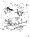
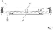
- FIGS. 1 and 2 are diagrams showing the drain structure of the prior art.
- the prior art is a vehicle-mounted device that is embedded in an instrument panel of a vehicle and that is kept installed while being tilted such that an operation screen side that is exposed inside a vehicle interior is lower in a side view.
- a vehicle-mounted device 1 includes a circuit board 12 where a connector 121 for connecting a cable from outside is mounted, and a case 16 in which the circuit board is housed.
- the case includes, on an opposite side from the operation screen, a rear wall 164 in which an opening portion 168 for exposing the connector is formed.
- the case includes a bottom wall 162 in which a drain hole 166 is formed, the bottom wall extending from a lower part of the rear wall toward the operation screen side.
- Patent literature 1 Japanese Patent Application Laid-Open No. 2021-154824
- a printed wiring board forming a part of a circuit board includes a penetration hole for positioning an electronic component, for example. Accordingly, when water stays on the printed wiring board, a part of the water may possibly enter the penetration hole. Water entering the penetration hole may be discharged to below the printed wiring board in the form of waterdrops.
- a size of a diameter of the penetration hole or an angle of the printed wiring board there is a problem that water is retained inside the penetration hole in the printed wiring board, thus staying on the printed wiring board and rusting a mounted component such as the connector.
- an object of the present invention is to provide an electronic device that allows water entering a penetration hole in a printed wiring board to be actively discharged.
- an electronic device comprises a printed wiring board including a penetration hole that has a circular shape and that penetrates a first surface and a second surface, an electronic component mounted on the first surface of the printed wiring board, a water guide member disposed on the second surface side of the printed wiring board, the water guide member at least partially facing the penetration hole, and a case that houses the printed wiring board, the electronic component, and the water guide member.
- a part, of the water guide member, facing the penetration hole has a protruding shape or includes a surface that is sloped away from the second surface, and the water guide member is disposed in such a way that the shortest distance to a centroid of a shape of an end part of the penetration hole on the second surface side is smaller than a radius of the largest circle that is insertable in the shape of the end part.
- the water guide member includes a protruding part that faces the penetration hole or a sloping surface that is at a predetermined angle relative to a penetration direction of the penetration hole, and the water guide member is disposed in such a way that the shortest distance to the centroid of the shape of the end part of the penetration hole on the second surface side is smaller than the radius of the largest circle that is insertable in the shape of the end part, and thus, water entering the penetration hole in the printed wiring board can be actively discharged.
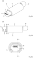
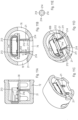
- FIG. 3A is a perspective view showing an example of the connector unit as an example of the electronic device according to the present embodiment, and FIG. 3B is a side view thereof, and FIG. 3C is a front view thereof.
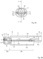
- FIG. 4A is a rear view of the connector unit shown in FIG. 3A
- FIG. 4B is a cross-sectional view taken along a line C-C in FIG. 4A .
- FIG. 5 is an exploded perspective view of the connector unit shown in FIG. 3A .
- potting resin 130 described later is not shown
- water guide members 20 and electronic components 50 are not shown.
- a connector unit 100 includes a printed wiring board 30, an interface connector 40, electronic components 50, a waterproof sealing member 60, a case 70, and a rear surface connector 90, and is formed with water guide members 20 described later (see FIGS. 9A to 9D ) as main elements.
- the printed wiring board 30 is a single or multi-layer wiring board that is mainly composed of glass epoxy resin, for example.
- FIG. 6A is a perspective view showing a printed circuit board 35 of the connector unit shown in FIG. 3A
- FIG. 6B is a side view of the printed wiring board 30 shown in FIG. 6A .
- the printed wiring board 30 has a flat plate shape including an upper surface (also referred to as "first surface”) 30A having a substantially rectangular shape and a lower surface (also referred to as “second surface”) 30B opposite to the upper surface 30A, and includes an end part 32 including an end surface corresponding to one end in a lengthwise direction, and an end part 33 including an end surface on an opposite side from the end part 32.
- the printed wiring board 30 includes a first region 30a that extends from the end part 32 in a direction of the end part 33, and a second region 30b that is adjacent to the first region 30a and that extends to the end part 33.
- the first region 30a is a region of the printed wiring board 30 from the end part 32 to the boundary 30c
- the second region 30b is a region of the printed wiring board 30 from the boundary 30c to the end part 33.
- the interface connector 40, the electronic components 50, and the rear surface connector 90 are mounted on the upper surface 30A of the printed wiring board 30.
- the printed wiring board 30 where the interface connector 40, the electronic components 50, and the rear surface connector 90 are mounted will be referred to as "printed circuit board 35".
- the printed circuit board 35 is housed in the case 70.
- the printed wiring board 30 includes two penetration holes 31b (see FIGS. 9A and 9D ).
- the penetration hole 31b of the present embodiment has a circular hole, and includes two end parts, namely, an end part 31b1 on the upper surface 30A side and an end part 31b2 on the lower surface 30B side (see FIG. 10 ).
- the interface connector 40 to be connected to a connector of a smartphone or the like is mounted on the upper surface 30A of the printed wiring board 30, on the end part 32 side of the first region 30a.
- the interface connector 40 is a type of an electronic component. As shown in FIGS. 4B to 6A , a terminal 42 of the interface connector 40 is covered by a metal shell 41 have a non-watertight structure, and is positioned facing outside of the case 70 through an opening portion 73 provided in a front plate part 74 of the case 70.
- the shell 41 includes a first end part 41a and a second end part 41b.
- the interface connector 40 includes two protruding parts 43b (see one protruding part 43b shown in FIG. 10 ) on the end part 41b side of a bottom surface, and includes, on both side surfaces of the shell 41, protruding parts 43c, 43d ( FIG. 6A ) in this order from the end part 41a side.
- the protruding part 43b is inserted in the penetration hole 31b provided in the printed wiring board 30.
- the protruding parts 43c, 43d are inserted in penetration holes 31c, 31d, respectively.
- the interface connector 40 is positioned on the printed wiring board 30.
- the penetration holes 31b, 31c, 31d are holes penetrating the upper surface 30A and the lower surface 30B of the printed wiring board 30, and are, in this case, formed as non-plated through holes.
- the interface connector 40 according to the present embodiment is a USB Type-C connector.
- the type of the interface connector 40 is not particularly limited as long as the interface connector is an interface connector having a non-watertight structure.
- the interface connector is an interface connector having a non-watertight structure.
- other interface connectors such as a USB Type-A connector or an HDMI (registered trademark) connector may be used. Because the interface connector 40 has a non-watertight structure, even when the interface connector 40 receives water through the opening portion 73, the water is not retained inside the interface connector 40 as long as the water is in small quantity, and the water is discharged outside the interface connector 40.
- the electronic components 50 which are surface mount components such as an IC chip and a capacitor, are mounted on the upper surface 30A of the printed wiring board 30, on the second region 30b side.
- a plurality of electronic components 50 are mounted, as shown in FIG. 6A .
- the electronic component 50 according to the present embodiment is an electronic component of a different type from the interface connector 40 and the rear surface connector 90 described later.
- the number of electronic components 50 on the printed wiring board 30 is not limited to plural.
- the first region 30a side inside the case 70 is a non-waterproof region
- the second region 30b side is a waterproof region.
- the electronic components 50 according to the present embodiment may include an electronic component that requires high waterproofness than the interface connector 40.
- the connector unit 100 of the present embodiment can be implemented without the electronic components 50, the electronic components 50 do not necessarily have to be mounted.
- FIG. 7A is a perspective view of the printed circuit board 35 where the waterproof sealing member 60 is integrally formed.
- FIG. 7B is a cross-sectional view seen from the interface connector 40 side, where the connector unit 100 is cut along a surface including the boundary 30c. In FIG. 7B , the printed wiring board 30 and the rear surface connector 90 on a backward side (a rear side) of the boundary 30c are not shown.
- the waterproof sealing member 60 is integrally formed with the printed wiring board 30 by tightly contacting the printed wiring board 30 while extending along and covering the outer periphery 30c1 of the boundary 30c of the printed wiring board 30.
- the waterproof sealing member 60 formed on the printed wiring board 30 includes pressing surfaces 60A, 60B, 60C, and 60D that press an inner surface of a tubular part 72 when inserted inside the case 70.
- the pressing surface 60A and the pressing surface 60B, the pressing surface 60B and the pressing surface 60C, the pressing surface 60C and the pressing surface 60D, and the pressing surface 60D and the pressing surface 60A are continuous to each other, and a surface that is continuous as a whole is formed.
- the pressing surfaces 60A, 60B, 60C, and 60D press an inner periphery 72c that is an inner periphery of the tubular part 72 of the case 70 and that faces toward the outer periphery 30c1, and are thus in close contact with the inner surface of the tubular part 72.
- the waterproof sealing member 60 is formed in the above manner, the waterproof sealing member 60 separates inside of the case 70 into the first region 30a side and the second region 30b side.
- the second region 30b side of the inside of the case 70 according to the present embodiment is a waterproof region.
- the potting resin 130 is injected or the rear surface connector 90 is provided, as will be described later.
- the waterproof sealing member 60 and making the second region 30b side inside the case 70 a waterproof region a waterproof function is achieved on the second region 30b side even when water enters from a rear end side of the case 70 (a side of the case 70 opposite from the front plate part 74), not to mention a case where water enters through the opening portion 73 of the case 70. Accordingly, the electronic components 50 and the printed wiring board 30 on the second region 30b side inside the case 70 are not affected by water regardless of which orientation the connector unit 100 is attached to another device of a vehicle or the like where the connector unit 100 is mounted.
- the waterproof sealing member 60 is integrally formed with the printed wiring board 30 by insert molding, for example.
- the waterproof sealing member 60 is not limited to be formed as one member, and may instead be a plurality of non-annular members that are separately formed from the printed wiring board 30, for example.
- the printed circuit board 35 where the waterproof sealing member 60 is integrally formed is housed inside the case 70.
- the case 70 is a molded article formed from thermoplastic resin such as ABS.
- the case 70 includes tubular parts 71 and 72 having rectangular tube shapes, and the front plate part 74 positioned on a front end of the tubular part 72.
- the tubular part 71 has a tubular shape that is a size larger than the tubular part 72.
- the opening portion 73 that allows insertion/removal of a mating connector of the interface connector 40 is formed in the front plate part 74 of the tubular part 72.
- Six drain holes 76 are formed in the tubular part 72, or in other words, on the first region 30a side of the case 70, two each in three directions. The opening portion 73 and the drain holes 76 each communicate with an inner space of the tubular part 72.
- the drain holes 76 are provided, even if water enters from the opening portion 73 side, the water is not kept retained on the first region 30a side inside the case 70, and is discharged outside the case 70 through the drain holes 76. Because the interface connector 40 has a non-watertight structure, water received by the interface connector 40 is discharged outside the interface connector 40. As a result, the water is temporarily retained on the first region 30a side inside the case 70; however, the water discharged from the interface connector 40 is also eventually discharged outside the case 70 through the drain holes 76. Accordingly, even if a great amount of water is received from the opening portion 73, the water is hardly kept retained on the first region 30a side inside the case 70.
- the printed circuit board 35 where the waterproof sealing member 60 is integrally formed is pushed and inserted (inserted under pressure) from a rear end side of the tubular part 71 (opposite side of the case 70 from the front plate part 74), and is housed inside the case 70.
- sliders 71a, 71b, 71c, and 71d are formed on an inner surface of the tubular part 71, on side surface regions on both left and right sides.
- the inside of the case 70 is separated into the first region 30a side and the second region 30b side by the waterproof sealing member 60. That is, in the case where the waterproof sealing member 60 is used as the waterproof sealing member, the pressing surfaces 60A, 60B, 60C, and 60D of the waterproof sealing member 60 press the inner surface of the tubular part 72, as shown in FIG. 7B .
- the waterproof sealing member 60 thus separates the inside of the case 70 into the first region 30a side and the second region 30b side.
- the rear surface connector 90 to be connected to a harness connector (not shown) is mounted on the upper surface 30A of the printed wiring board 30.
- the rear surface connector 90 is a type of an electronic component.
- the rear surface connector 90 includes a housing 91 and terminals 92.
- the housing 91 has a tubular shape, and is formed from the fitting part 91a to be fitted with the harness connector mentioned above, and a base part 91b that covers a base end of the fitting part 91a.
- two terminal insertion holes 91c are formed in the base part 91b.
- the rear surface connector 90 according to the present embodiment includes two terminals 92.
- the terminal 92 has a shape that is bent in an L-shape, and a pair of protrusions 92a protruding in both sides in a width direction is formed on one side of the L-shape. As shown in FIGS. 4B and 5 , the terminal 92 is attached to the housing 91 by having the one side of the L-shape pushed into the terminal insertion hole 91c. The side of the terminal 92 that is pushed in is exposed inside the fitting part 91a so as to be able to be connected to the harness connector mentioned above. The other side of the L-shape of the terminal 92 is inserted and soldered to a through hole 31a provided on the end part 33 side of the printed wiring board 30.
- the potting resin 130 is injected on the second region 30b side inside the case 70.
- a material of the potting resin 130 include, but are not limited to, urethane resin, epoxy resin, and silicone resin.
- the injected potting resin 130 is indicated using a reference numeral, and is shown with no patterns without using diagonal lines or the like so that the potting resin 130 is distinguishable from the tubular part 71 and the printed wiring board 30.
- injection of the potting resin 130 is performed until the second region 30b side inside the case 70 is filled with the potting resin 130. Due to being filled with the potting resin 130, the inside of the case 70 may be such that the first region 30a side is a non-waterproof region, and the second region 30b side is a waterproof region.
- Waterproofness may be achieved by placing the second region 30b side inside the case 70 in a hollow state without injecting the potting resin 130, and by providing a rear surface cover 80 on the tubular part 71.
- FIG. 8A is a rear view showing an example of the connector unit, where the rear surface cover 80 is included
- FIG. 8B is a cross-sectional view taken along a line C-C in FIG. 8A
- the water guide members 20 and the electronic components 50 are not shown.
- the second region 30b side inside the case 70 is not filled with the potting resin 130. Instead, a rear end of the tubular part 71 of the case 70, or in other words, an end part of the case 70 on the second region 30b side is covered by the rear surface cover 80.
- the rear surface cover 80 includes a circular flat plate having a same shape as an inner diameter of the tubular part 71.
- a waterproof function is achieved on the second region 30b side inside the case 70.
- the rear surface cover 80 may be integrally formed between the fitting part 91a and the base part 91b.
- the base part 91b is thereby made a part of the rear surface cover 80, and the fitting part 91a is made to protrude rearward from the rear surface cover 80.
- the rear surface cover 80 may instead be formed as a separate body from the rear surface connector 90.
- the rear surface cover 80 may be formed as a structure that holds the rear surface connector 90. It is conceivable to form the rear surface cover 80 from, but not limited to, a homogeneous material as the waterproof sealing member 60.
- the second region 30b side inside the case 70 may be filled with the potting resin 130 to further increase the waterproof function. Additionally, in the case where the potting resin 130 is not injected, a moisture prevention coat may be applied on the printed wiring board 30 from the standpoint of waterproofness even when the rear surface cover 80 is provided.
- a coating agent a normal-temperature type fluorine coating agent may be used, or a coating agent that uses urethane-, acrylic-, or silicone-based resin as a film component may be used, for example.
- the rear surface cover 80 may achieve a waterproof function on the second region 30b side inside the case 70, and also, the rear surface cover 80 may achieve the waterproof function at a lower cost than the potting resin 130.
- FIGS. 9A to 9D are diagrams for describing the water guide members 20, and FIG. 9A is a diagram showing a region, on a cross-sectional view A-A in FIG. 3C , from the front plate part 74 to a cross-sectional line B-B in FIG. 3B , FIG. 9B is a cross-sectional view B-B in FIG. 3B , FIG. 9C is a perspective view of FIG. 9B as viewed from upper left, and FIG. 9D is a perspective view of FIG. 9B as viewed from lower left.
- FIG. 10 is an enlarged view of a region indicated by a dash-dotted line in FIG. 9A .
- two water guide members 20 are provided inside the tubular part 72, on the lower surface 30B side of the printed wiring board 30.
- Each water guide member 20 is formed from a columnar part 201 having a columnar shape, and a conical part 202 having a conical shape having a side surface that forms an apex angle ⁇ (see FIG. 10 ), and the water guide member 20 has a protruding shape as a whole.
- the columnar part 201 forms a base part of the water guide member 20, and is provided in such a way that an axis of the columnar shape extends upright from a bottom surface inside the tubular part 72 toward the lower surface 30B of the printed wiring board 30.
- the conical part 202 is provided with an upper surface of the columnar part 201 as a start point, and is provided in such a way that an axis of the conical shape extends upright along a same axis as the axis of the columnar part 201 toward the lower surface 30B of the printed wiring board 30.
- an apex of the conical part 202 is formed as a distal end part 203 that is rounded into a semispherical shape.
- the water guide member 20 may be obtained by injection molding using thermoplastic resin such as ABS, but the material is not limited thereto.
- the water guide member 20 of the present embodiment is integrally formed with the tubular part 72, but may instead be formed separately from the tubular part 72.
- the water guide member 20 is formed separately from the tubular part 72, a bottom surface of the columnar part 201 and the bottom surface inside the tubular part 72 are joined using an adhesive or the like and are fixed to each other to prevent relative movement.
- the water guide member 20 of the present embodiment is solid, but may instead be hollow.
- a cross-sectional shape of each of the columnar part 201 and the conical part 202 of the present embodiment is a true circle, but the cross-sectional shape is not limited thereto, and may instead be a different circular shape such as an ellipse or a polygon.
- the water guide member 20 is disposed such that the shortest distance to a centroid of a shape of the end part 31b2, on the lower surface (second surface) 30B side, of the penetration hole 31b in the printed wiring board 30 is smaller than a radius of the largest circle that is insertable in the shape of the end part 31b2.
- the shortest distance between the water guide member 20 and the centroid of the hole in the end part 31b2 is a distance X.
- the water guide member 20 When a diameter of the circle of the end part 31b2 is given as D, the water guide member 20 is provided at a position where a relationship of X ⁇ (D/2) is maintained.
- X ⁇ (D/2) By maintaining the relationship of X ⁇ (D/2) regardless of whether the axis 31bJ and the axis 202J are on the same axis, at least a part of the water guide member 20 is positioned within a semispherical region protruding downward from the centroid (the center) of the hole of the end part 31b2. Accordingly, at least a part of the water guide member 20 is disposed at a position facing the penetration hole 31b.
- the connector unit 100 receives water from the opening portion 73 side and a part of the received water enters the penetration hole 31b in the printed wiring board 30 will be considered.
- the situation may change depending on a size of a diameter of the penetration hole 31b, an amount of received water, and other conditions, the water entering the penetration hole 31b is possibly retained while protruding downward from the end part 31b2.
- the water may not drip from the printed wiring board 30 in the form of waterdrops, and may stay on the printed wiring board 30 while being exposed below from the printed wiring board 30 in a shape resembling a mountain or a sphere.
- the first region 30a side inside the case 70 is a non-waterproof region, and a case is conceivable where the waterproof sealing member 60 acts as a wall and water that is received on the upper surface 30A side of the printed wiring board 30 remains and enters the penetration hole 31b.
- the water guide member 20 is disposed in such a way that the shortest distance to the centroid of the shape of the end part 31b2, on the lower surface (second surface) 30B side, of the penetration hole 31b is smaller than the radius of the largest circle that is insertable in the shape of the end part 31b2. Accordingly, when water that is received protrudes downward from the end part 31b2, the water comes into contact with the distal end part 203.
- the side surface of the conical part 202 having a sloping surface serves as a flow path, and water that was supposed to stay in the penetration hole 31b is made to flow downward. Accordingly, the water guide member 20 may actively discharge water entering the penetration hole 31b in the printed wiring board 30.
- a shape of the penetration hole 31b and the shape of the end part 31b2 according to the present embodiment are each not limited to a true circle, and may be another shape such as an ellipse or a quadrilateral.
- the water guide member 20 is disposed at a position at which the shortest distance to a centroid of the ellipse (that is, a center of the ellipse) at the end part 31b2 is smaller than a radius of the largest circle (that is, a minor radius of the ellipse) that is insertable in the shape of the end part 31b2.
- the water guide member 20 is disposed at a position at which the shortest distance to a centroid of the rectangle (that is, a center of the rectangle) of the end part 31b2 is smaller than a radius of the largest circle that is insertable in the shape of the end part 31b2 (that is, a length that is half the short side of the rectangle).
- a quadrilateral here includes a shape that is not exactly a quadrilateral due to four corners being rounded, for example, but that is equivalent to a quadrilateral.
- the water guide member 20 is (a) not limited to a specific material, (b) allowed to be formed separately from the tubular part 72, and (c) allowed to be hollow.
- FIGS. 11A to 11E are diagrams for describing the water guide member 21, and FIGS. 11A to 11D are diagrams corresponding to FIGS. 9A to 9D , respectively, and FIG. 11E is a cross-sectional view E-E in FIG. 11B .
- each water guide member 21 is formed from a columnar part 211 and a truncated conical part 212, and has a protruding shape that is disposed at a position facing the penetration hole 31b. That is, when compared with the water guide member 20, the columnar part 211 basically has a same shape as the columnar part 201, but a shape of the truncated conical part 212 is changed from the conical shape of the conical part 202 to a truncated conical shape.
- the distal end part 203 is not semispherical, and is changed to a distal end part 213 that is formed to be flat.
- groove parts 214 having a substantially fan-shaped cross section are provided at four positions on the water guide member 21, the groove parts extending between both end parts, or in other words, between an upper end of the truncated conical part 212 and a lower end of the columnar part 211 ( FIG. 11E ).
- the groove parts 214 serve to promote downward flow of water by capillary action. Conditions regarding the shortest distance to the centroid of the shape of the end part 31b2 imposed on the water guide member 21 are the same those on the water guide member 20.
- water entering the penetration hole 31b in the printed wiring board 30 can be actively discharged. Furthermore, because the groove parts 214 are provided, water that is received can be actively guided along a direction of the groove parts 214.
- a cross-sectional shape of each of the columnar part 211 and the truncated conical part 212 of the present embodiment is a true circle, but the cross-sectional shape is not limited thereto, and other circular shapes and polygons may also be adopted.
- FIGS. 12A to 12E are diagrams for describing the water guide member 22, and FIGS. 12A to 12D are diagrams corresponding to FIGS. 9A to 9D , respectively, and FIG. 12E is an enlarged view of a region indicated by a dash-dotted line in FIG. 12D .
- each water guide member 22 has a shape of a quadrangular prism having base surfaces of an isosceles trapezoid, where one base surface of the isosceles trapezoid is in contact with an inner surface of the front plate part 74 and is provided protruding toward the waterproof sealing member 60 side with the inner surface of the front plate part 74 as a start point (i.e., protruding in a horizontal direction in FIG. 12A ).
- a surface that forms a side surface of the quadrangular prism and that is a surface of the isosceles trapezoid on a lower base side is in contact with a lower surface inside the tubular part 72.
- a surface that forms a side surface of the quadrangular prism and that is a surface of the isosceles trapezoid on an upper base side is disposed such that one end of the surface in a lengthwise direction ("end part 223a" shown in FIG. 12E ) faces the penetration hole 31b in the printed wiring board 30.
- the water guide member 22 also has a protruding shape that is substantially mountain-shaped relative to the penetration hole 31b.
- a groove part 224 having a sideways U-shape cross-section is provided to each end part 223a, from the upper base to the lower base of the isosceles trapezoid (in a vertical direction in FIG. 12B ).
- a size of the sideways U-shape of the groove part 224 is continually increased from the upper base toward the lower base such that a thickness of the groove is constant.
- the water guide member 22 uses the end part 223a and its periphery as a part (referred to here as "distal end part 223") corresponding to the distal end part 203 of the water guide member 20. That is, the distal end part 223 including the end part 223a is disposed facing the penetration hole 31b. Conditions regarding the shortest distance to the centroid of the shape of the end part 31b2 imposed on the water guide member 22 are the same those on the water guide member 20.
- water entering the penetration hole 31b in the printed wiring board 30 can be actively discharged. Furthermore, because the groove part 224 is provided, water that is received can be actively guided along a direction of the groove part 224. Moreover, because the water guide member 22 is in contact with the inner surface of the front plate part 74 and also with the lower surface inside the tubular part 72, the water guide member 22 may serve also as a reinforcement member for the front plate part 74 and the tubular part 72.
- FIGS. 13A to 13D are diagrams for describing the water guide member 23, and are diagrams corresponding to FIGS. 9A to 9D , respectively.
- FIG. 14 is an enlarged view of a region indicated by a dash-dotted line in FIG. 13A .
- the water guide member 23 of a present modification is formed to protrude toward the waterproof sealing member 60 side with the inner surface of the front plate part 74 as a start point.
- the water guide member 23 is formed from a base part 231, two leg parts 232, and a reinforcement part 233.
- the base part 231 has a flat plate shape that protrudes, in the form of a quadrangular prism having a rectangular bottom surface, toward the waterproof sealing member 60 side with the inner surface of the front plate part 74 as a start point. As shown in FIG.
- a thickness of the base part 231 is constant in a region including a surface 231a, and a region including a surface 231b is formed to be thinner, the closer to the waterproof sealing member 60. That is, the surface 231b is sloped away from the lower surface (second surface) 30B at an angle ⁇ relative to the surface 231a.
- the two leg parts 232 are provided extending in a curved shape from both end parts of the base part 231 in a longitudinal direction.
- the base part 231 and the two leg parts 232 are continuous, and form a C-shape as a whole.
- the leg parts 232 each have a shape that protrudes, by a same length as the base part 231, toward the waterproof sealing member 60 side with the inner surface of the front plate part 74 as a start point.
- a thickness of the leg part 232 is constant in a predetermined region corresponding to the surface 231a, but as with the base part 231, a region corresponding to the surface 231b is formed to be thinner, the closer to the waterproof sealing member 60.
- the reinforcement part 233 extends, toward the waterproof sealing member 60 side with the inner surface of the front plate part 74 as a start point, in such a way as to reinforce the base part 231 at a center position of the base part 231 in the longitudinal direction.
- a length of extension is slightly smaller than the base part 231.
- Each water guide member 23 is formed on the lower surface 30B side of the printed wiring board 30 below the interface connector 40 in a manner protruding toward the waterproof sealing member 60 side with the inner surface of the front plate part 74 as a start point.
- Each base part 231 is disposed with at least a part thereof facing the respective penetration hole 31b to serve the role of the distal end part 203 of the water guide member 20 described above.
- the water guide member 23 includes a sloping surface (the surface 231b) that is at a predetermined angle (90 degrees - ⁇ ) relative to a penetration direction of the penetration hole 31b, and is disposed such that the shortest distance to the centroid of the shape of the end part 31b2 (a distance X in FIG. 14 ) is smaller than the radius of the largest circle that is insertable in the shape of the end part 31b2. That is, in the example in FIG. 14 , it is provided at a position where the relationship of X ⁇ (D/2) is maintained.
- water entering the penetration hole 31b in the printed wiring board 30 can be actively discharged.
- a thinned portion of the base part 231, a curved portion of the leg part 232, and a thinned portion of the leg part 232 each serve to guide water in a direction along the portion.
- the water guide member 23 forms a C-shape by the base part 231 and the leg parts 232 and includes the 233 for reinforcing the base part 231, the water guide member 23 has higher rigidity than the water guide members 20, 21, 23.
- the water guide member 23 is provided in contact with the inner surface of the front plate part 74. Accordingly, even if a force is applied to the front plate part 74 while a mating connector of the interface connector 40 is being inserted/removed through the opening portion 73, the front plate part 74 is less likely to be deformed or damaged.
- the water guide members 20, 21, 22, 23 are provided facing the two penetration holes 31b in the printed wiring board 30, but depending on conditions such as restrictions inside the case 70, the water guide member 20 may be provided only for one of the penetration holes 31b. It is needless to say the connector unit 100 described in the present embodiment may be changed as appropriate within the scope of the present invention.
Landscapes
- Engineering & Computer Science (AREA)
- Microelectronics & Electronic Packaging (AREA)
- Connector Housings Or Holding Contact Members (AREA)
- Casings For Electric Apparatus (AREA)
- Printing Elements For Providing Electric Connections Between Printed Circuits (AREA)
- Mounting Of Printed Circuit Boards And The Like (AREA)
Abstract
Description
- The present invention relates to a drain structure of an electronic device.
- Some prior art electronic devices having a drain structure are capable of discharging water to outside even if water enters inside a case (for example, see Patent literature 1).
FIGS. 1 and2 are diagrams showing the drain structure of the prior art. The prior art is a vehicle-mounted device that is embedded in an instrument panel of a vehicle and that is kept installed while being tilted such that an operation screen side that is exposed inside a vehicle interior is lower in a side view. A vehicle-mounted device 1 includes acircuit board 12 where a connector 121 for connecting a cable from outside is mounted, and acase 16 in which the circuit board is housed. Furthermore, the case includes, on an opposite side from the operation screen, arear wall 164 in which an opening portion 168 for exposing the connector is formed. The case includes abottom wall 162 in which adrain hole 166 is formed, the bottom wall extending from a lower part of the rear wall toward the operation screen side. - Patent literature 1:
Japanese Patent Application Laid-Open No. 2021-154824 - However, with respect to the vehicle-mounted device 1 of Patent literature 1, a technique is merely disclosed according to which water guided to the
bottom wall 162 is discharged from thedrain hole 166. Depending on a mode of use of the electronic device, not all the water reaches thebottom wall 162, and water is possibly retained on other components such as a circuit board, for example. - In many cases, a printed wiring board forming a part of a circuit board includes a penetration hole for positioning an electronic component, for example. Accordingly, when water stays on the printed wiring board, a part of the water may possibly enter the penetration hole. Water entering the penetration hole may be discharged to below the printed wiring board in the form of waterdrops. However, depending on conditions such as a size of a diameter of the penetration hole or an angle of the printed wiring board, there is a problem that water is retained inside the penetration hole in the printed wiring board, thus staying on the printed wiring board and rusting a mounted component such as the connector.
- In view of the problem described above, an object of the present invention is to provide an electronic device that allows water entering a penetration hole in a printed wiring board to be actively discharged.
- To solve the problem described above, an electronic device according to a present embodiment comprises a printed wiring board including a penetration hole that has a circular shape and that penetrates a first surface and a second surface, an electronic component mounted on the first surface of the printed wiring board, a water guide member disposed on the second surface side of the printed wiring board, the water guide member at least partially facing the penetration hole, and a case that houses the printed wiring board, the electronic component, and the water guide member.
- A part, of the water guide member, facing the penetration hole has a protruding shape or includes a surface that is sloped away from the second surface, and the water guide member is disposed in such a way that the shortest distance to a centroid of a shape of an end part of the penetration hole on the second surface side is smaller than a radius of the largest circle that is insertable in the shape of the end part.
- With the electronic device of the present embodiment, the water guide member includes a protruding part that faces the penetration hole or a sloping surface that is at a predetermined angle relative to a penetration direction of the penetration hole, and the water guide member is disposed in such a way that the shortest distance to the centroid of the shape of the end part of the penetration hole on the second surface side is smaller than the radius of the largest circle that is insertable in the shape of the end part, and thus, water entering the penetration hole in the printed wiring board can be actively discharged.
-
- [
FIG. 1] FIG. 1 is a diagram for describing a prior art electronic device including a drain structure; - [
FIG. 2] FIG. 2 is a diagram for describing the priori art electronic device including the drain structure; - [
FIG. 3] FIG. 3A is a perspective view showing an example of a connector unit as an example of an electronic device according to a present embodiment, -
FIG. 3B is a side view showing the example of the connector unit as an example of the electronic device according to the present embodiment, and -
FIG. 3C is a front view showing the example of the connector unit as an example of the electronic device according to the present embodiment; - [
FIG. 4] FIG. 4A is a rear view of the connector unit shown inFIG. 3A and -
FIG. 4B is a cross-sectional view taken along a line C-C inFIG. 4A ; - [
FIG. 5] FIG. 5 is an exploded perspective view of the connector unit shown inFIG. 3A ; - [
FIG. 6] FIG. 6A is a perspective view showing a printedcircuit board 35 of the connector unit shown inFIG. 3A , andFIG. 6B is a side view of a printedwiring board 30 shown inFIG. 6A ; - [
FIG. 7] FIG. 7A is a perspective view of the printedcircuit board 35 where awaterproof sealing member 60 is integrally formed, andFIG. 7B is a cross-sectional view seen from aninterface connector 40 side, where aconnector unit 100 is cut along a surface including aboundary 30c; - [
FIG. 8] FIG. 8A is a rear view showing an example of the connector unit, where arear surface cover 80 is included andFIG. 8B is a cross-sectional view taken along a line C-C inFIG. 8A ; - [
FIG. 9] FIG. 9A is a diagram for describing awater guide member 20, and is a drawing showing a region, on a cross-sectional view A-A inFIG. 3C , from afront plate part 74 to a cross-sectional line B-B inFIG. 3B ,FIG. 9B is a diagram for describing thewater guide member 20, and is a cross-sectional view B-B inFIG. 3B ,FIG. 9C is a diagram for describing thewater guide member 20, and is a perspective view ofFIG. 9B as viewed from upper left, andFIG. 9D is a diagram for describing thewater guide member 20, and is a perspective view showingFIG. 9B from a lower left side; - [
FIG. 10] FIG. 10 is an enlarged view of a region indicated by a dash-dotted line inFIG. 9A ; - [
FIG. 11] FIG. 11A is a diagram for describing awater guide member 21, and is a diagram corresponding toFIG. 9A ,FIG. 11B is a diagram for describing thewater guide member 21, and is a diagram corresponding toFIG. 9B ,FIG. 11C is a diagram for describing thewater guide member 21, and is a diagram corresponding toFIG. 9C ,FIG. 11D is a diagram for describing thewater guide member 21, and is a diagram corresponding toFIG. 9D , andFIG. 11E is a diagram for describing thewater guide member 21, and is a cross-sectional view E-E inFIG. 11B ; - [
FIG. 12] FIG. 12A is a diagram for describing awater guide member 22, and is a diagram corresponding toFIG. 9A ,FIG. 12B is a diagram for describing thewater guide member 22, and is a diagram corresponding toFIG. 9B ,FIG. 12C is a diagram for describing thewater guide member 22, and is a diagram corresponding toFIG. 9C ,FIG. 12D is a diagram for describing thewater guide member 22, and is a diagram corresponding toFIG. 9D , andFIG. 12E is a diagram for describing thewater guide member 22, and is an enlarged view of a region indicated by a dash-dotted line inFIG. 12D ; - [
FIG. 13] FIG. 13A is a diagram for describing awater guide member 23, and is a diagram corresponding toFIG. 9A ,FIG. 13B is a diagram for describing thewater guide member 23, and is a diagram corresponding toFIG. 9B ,FIG. 13C is a diagram for describing thewater guide member 23, and is a diagram corresponding toFIG. 9C , andFIG. 13D is a diagram for describing thewater guide member 23, and is a diagram corresponding toFIG. 9D ; and - [
FIG. 14] FIG. 14 is an enlarged view of a region indicated by a dash-dotted line inFIG. 13A . - Hereinafter, an embodiment of the present invention will be described with reference to the drawings. In the description, a case where a connector unit is used as an example of an electronic device will be described. However, in the present invention, the type of the electronic device is not limited to the connector unit as long as the electronic device includes a printed wiring board including a penetration hole described later, and application to other electronic devices is also possible. Additionally, in the following description, structural parts having a same function are denoted by a same number, and a redundant description will be omitted.
-
FIG. 3A is a perspective view showing an example of the connector unit as an example of the electronic device according to the present embodiment, andFIG. 3B is a side view thereof, andFIG. 3C is a front view thereof.FIG. 4A is a rear view of the connector unit shown inFIG. 3A , andFIG. 4B is a cross-sectional view taken along a line C-C inFIG. 4A .FIG. 5 is an exploded perspective view of the connector unit shown inFIG. 3A . InFIG. 4A , pottingresin 130 described later is not shown, and inFIG. 4B ,water guide members 20 andelectronic components 50 are not shown. - As shown in
FIG. 5 , aconnector unit 100 according to the present embodiment includes a printedwiring board 30, aninterface connector 40,electronic components 50, awaterproof sealing member 60, acase 70, and arear surface connector 90, and is formed withwater guide members 20 described later (seeFIGS. 9A to 9D ) as main elements. - The printed
wiring board 30 is a single or multi-layer wiring board that is mainly composed of glass epoxy resin, for example.FIG. 6A is a perspective view showing a printedcircuit board 35 of the connector unit shown inFIG. 3A , andFIG. 6B is a side view of the printedwiring board 30 shown inFIG. 6A . - As shown in
FIGS. 6A and 6B , the printedwiring board 30 according to the present embodiment has a flat plate shape including an upper surface (also referred to as "first surface") 30A having a substantially rectangular shape and a lower surface (also referred to as "second surface") 30B opposite to theupper surface 30A, and includes anend part 32 including an end surface corresponding to one end in a lengthwise direction, and anend part 33 including an end surface on an opposite side from theend part 32. The printedwiring board 30 includes afirst region 30a that extends from theend part 32 in a direction of theend part 33, and asecond region 30b that is adjacent to thefirst region 30a and that extends to theend part 33. When a surface at a boundary between thefirst region 30a and thesecond region 30b is defined as aboundary 30c, thefirst region 30a is a region of the printedwiring board 30 from theend part 32 to theboundary 30c, and thesecond region 30b is a region of the printedwiring board 30 from theboundary 30c to theend part 33. - The
interface connector 40, theelectronic components 50, and therear surface connector 90 are mounted on theupper surface 30A of the printedwiring board 30. In the present embodiment, the printedwiring board 30 where theinterface connector 40, theelectronic components 50, and therear surface connector 90 are mounted will be referred to as "printedcircuit board 35". As shown inFIG. 4B , the printedcircuit board 35 is housed in thecase 70. Additionally, the printedwiring board 30 includes twopenetration holes 31b (seeFIGS. 9A and 9D ). Thepenetration hole 31b of the present embodiment has a circular hole, and includes two end parts, namely, an end part 31b1 on theupper surface 30A side and an end part 31b2 on thelower surface 30B side (seeFIG. 10 ). - The
interface connector 40 to be connected to a connector of a smartphone or the like is mounted on theupper surface 30A of the printedwiring board 30, on theend part 32 side of thefirst region 30a. - The
interface connector 40 is a type of an electronic component. As shown inFIGS. 4B to 6A , aterminal 42 of theinterface connector 40 is covered by ametal shell 41 have a non-watertight structure, and is positioned facing outside of thecase 70 through an openingportion 73 provided in afront plate part 74 of thecase 70. Theshell 41 includes afirst end part 41a and asecond end part 41b. Theinterface connector 40 includes two protrudingparts 43b (see one protrudingpart 43b shown inFIG. 10 ) on theend part 41b side of a bottom surface, and includes, on both side surfaces of theshell 41, protrudingparts FIG. 6A ) in this order from theend part 41a side. The protrudingpart 43b is inserted in thepenetration hole 31b provided in the printedwiring board 30. In the same manner, the protrudingparts penetration holes 31c, 31d, respectively. When the protrudingparts interface connector 40 is positioned on the printedwiring board 30. The penetration holes 31b, 31c, 31d are holes penetrating theupper surface 30A and thelower surface 30B of the printedwiring board 30, and are, in this case, formed as non-plated through holes. Theinterface connector 40 according to the present embodiment is a USB Type-C connector. However, the type of theinterface connector 40 is not particularly limited as long as the interface connector is an interface connector having a non-watertight structure. For example, other interface connectors such as a USB Type-A connector or an HDMI (registered trademark) connector may be used. Because theinterface connector 40 has a non-watertight structure, even when theinterface connector 40 receives water through the openingportion 73, the water is not retained inside theinterface connector 40 as long as the water is in small quantity, and the water is discharged outside theinterface connector 40. - The
electronic components 50, which are surface mount components such as an IC chip and a capacitor, are mounted on theupper surface 30A of the printedwiring board 30, on thesecond region 30b side. With respect to theelectronic components 50 according to the present embodiment, a plurality ofelectronic components 50 are mounted, as shown inFIG. 6A . Theelectronic component 50 according to the present embodiment is an electronic component of a different type from theinterface connector 40 and therear surface connector 90 described later. However, the number ofelectronic components 50 on the printedwiring board 30 is not limited to plural. Moreover, as described later, in the present embodiment, thefirst region 30a side inside thecase 70 is a non-waterproof region, and thesecond region 30b side is a waterproof region. Accordingly, theelectronic components 50 according to the present embodiment may include an electronic component that requires high waterproofness than theinterface connector 40. Additionally, in the case where theconnector unit 100 of the present embodiment can be implemented without theelectronic components 50, theelectronic components 50 do not necessarily have to be mounted. - A
waterproof sealing member 60 formed from a hot melt material is formed on an outer periphery 30c1 of theboundary 30c of the printedwiring board 30.FIG. 7A is a perspective view of the printedcircuit board 35 where thewaterproof sealing member 60 is integrally formed.FIG. 7B is a cross-sectional view seen from theinterface connector 40 side, where theconnector unit 100 is cut along a surface including theboundary 30c. InFIG. 7B , the printedwiring board 30 and therear surface connector 90 on a backward side (a rear side) of theboundary 30c are not shown. - As shown in
FIGS. 7A and 7B , thewaterproof sealing member 60 is integrally formed with the printedwiring board 30 by tightly contacting the printedwiring board 30 while extending along and covering the outer periphery 30c1 of theboundary 30c of the printedwiring board 30. As shown inFIG. 7B , thewaterproof sealing member 60 formed on the printedwiring board 30 includespressing surfaces tubular part 72 when inserted inside thecase 70. Thepressing surface 60A and thepressing surface 60B, thepressing surface 60B and thepressing surface 60C, thepressing surface 60C and thepressing surface 60D, and thepressing surface 60D and thepressing surface 60A are continuous to each other, and a surface that is continuous as a whole is formed. Thepressing surfaces inner periphery 72c that is an inner periphery of thetubular part 72 of thecase 70 and that faces toward the outer periphery 30c1, and are thus in close contact with the inner surface of thetubular part 72. When thewaterproof sealing member 60 is formed in the above manner, thewaterproof sealing member 60 separates inside of thecase 70 into thefirst region 30a side and thesecond region 30b side. - Furthermore, the
second region 30b side of the inside of thecase 70 according to the present embodiment is a waterproof region. For example, to achieve the waterproof region, thepotting resin 130 is injected or therear surface connector 90 is provided, as will be described later. - By providing the
waterproof sealing member 60 and making thesecond region 30b side inside the case 70 a waterproof region, a waterproof function is achieved on thesecond region 30b side even when water enters from a rear end side of the case 70 (a side of thecase 70 opposite from the front plate part 74), not to mention a case where water enters through the openingportion 73 of thecase 70. Accordingly, theelectronic components 50 and the printedwiring board 30 on thesecond region 30b side inside thecase 70 are not affected by water regardless of which orientation theconnector unit 100 is attached to another device of a vehicle or the like where theconnector unit 100 is mounted. - The
waterproof sealing member 60 is integrally formed with the printedwiring board 30 by insert molding, for example. However, thewaterproof sealing member 60 is not limited to be formed as one member, and may instead be a plurality of non-annular members that are separately formed from the printedwiring board 30, for example. - The printed
circuit board 35 where thewaterproof sealing member 60 is integrally formed is housed inside thecase 70. For example, thecase 70 is a molded article formed from thermoplastic resin such as ABS. - As shown in
FIGS. 3A to 5 , thecase 70 includestubular parts front plate part 74 positioned on a front end of thetubular part 72. Thetubular part 71 has a tubular shape that is a size larger than thetubular part 72. The openingportion 73 that allows insertion/removal of a mating connector of theinterface connector 40 is formed in thefront plate part 74 of thetubular part 72. Six drain holes 76 are formed in thetubular part 72, or in other words, on thefirst region 30a side of thecase 70, two each in three directions. The openingportion 73 and the drain holes 76 each communicate with an inner space of thetubular part 72. - Because the drain holes 76 are provided, even if water enters from the opening
portion 73 side, the water is not kept retained on thefirst region 30a side inside thecase 70, and is discharged outside thecase 70 through the drain holes 76. Because theinterface connector 40 has a non-watertight structure, water received by theinterface connector 40 is discharged outside theinterface connector 40. As a result, the water is temporarily retained on thefirst region 30a side inside thecase 70; however, the water discharged from theinterface connector 40 is also eventually discharged outside thecase 70 through the drain holes 76. Accordingly, even if a great amount of water is received from the openingportion 73, the water is hardly kept retained on thefirst region 30a side inside thecase 70. - The printed
circuit board 35 where thewaterproof sealing member 60 is integrally formed is pushed and inserted (inserted under pressure) from a rear end side of the tubular part 71 (opposite side of thecase 70 from the front plate part 74), and is housed inside thecase 70. As shown inFIG. 4A ,sliders tubular part 71, on side surface regions on both left and right sides. When performing push-in insertion of the printedcircuit board 35 where thewaterproof sealing member 60 is integrally formed into thecase 70, an end part of the printedwiring board 30 in a width direction is inserted between thesliders 71a and 71b, and another end part is inserted and pushed in between thesliders FIG. 4B , theinterface connector 40, the electronic component 50s, and thewaterproof sealing member 60 on the printedwiring board 30, and therear surface connector 90 excluding afitting part 91a are housed inside thecase 70 together with the printedwiring board 30, at predetermined positions and at predetermined heights. - The inside of the
case 70 is separated into thefirst region 30a side and thesecond region 30b side by thewaterproof sealing member 60. That is, in the case where thewaterproof sealing member 60 is used as the waterproof sealing member, thepressing surfaces waterproof sealing member 60 press the inner surface of thetubular part 72, as shown inFIG. 7B . Thewaterproof sealing member 60 thus separates the inside of thecase 70 into thefirst region 30a side and thesecond region 30b side. - On the
end part 33 side of thesecond region 30b, therear surface connector 90 to be connected to a harness connector (not shown) is mounted on theupper surface 30A of the printedwiring board 30. Therear surface connector 90 is a type of an electronic component. As shown inFIG. 5 , therear surface connector 90 includes ahousing 91 andterminals 92. Thehousing 91 has a tubular shape, and is formed from thefitting part 91a to be fitted with the harness connector mentioned above, and abase part 91b that covers a base end of thefitting part 91a. As shown inFIG. 4A , twoterminal insertion holes 91c are formed in thebase part 91b. Therear surface connector 90 according to the present embodiment includes twoterminals 92. The terminal 92 has a shape that is bent in an L-shape, and a pair ofprotrusions 92a protruding in both sides in a width direction is formed on one side of the L-shape. As shown inFIGS. 4B and5 , the terminal 92 is attached to thehousing 91 by having the one side of the L-shape pushed into theterminal insertion hole 91c. The side of the terminal 92 that is pushed in is exposed inside thefitting part 91a so as to be able to be connected to the harness connector mentioned above. The other side of the L-shape of the terminal 92 is inserted and soldered to a throughhole 31a provided on theend part 33 side of the printedwiring board 30. - After the
waterproof sealing member 60 and the printedcircuit board 35 are housed inside thecase 70, thepotting resin 130 is injected on thesecond region 30b side inside thecase 70. Examples of a material of thepotting resin 130 include, but are not limited to, urethane resin, epoxy resin, and silicone resin. InFIG. 4B , the injectedpotting resin 130 is indicated using a reference numeral, and is shown with no patterns without using diagonal lines or the like so that thepotting resin 130 is distinguishable from thetubular part 71 and the printedwiring board 30. As shown inFIG. 4B , injection of thepotting resin 130 is performed until thesecond region 30b side inside thecase 70 is filled with thepotting resin 130. Due to being filled with thepotting resin 130, the inside of thecase 70 may be such that thefirst region 30a side is a non-waterproof region, and thesecond region 30b side is a waterproof region. - Waterproofness may be achieved by placing the
second region 30b side inside thecase 70 in a hollow state without injecting thepotting resin 130, and by providing a rear surface cover 80 on thetubular part 71. -
FIG. 8A is a rear view showing an example of the connector unit, where therear surface cover 80 is included, andFIG. 8B is a cross-sectional view taken along a line C-C inFIG. 8A . InFIG. 8B , thewater guide members 20 and theelectronic components 50 are not shown. Unlike as inFIGS. 4A and 4B , with theconnector unit 100 shown inFIGS. 8A and 8B , thesecond region 30b side inside thecase 70 is not filled with thepotting resin 130. Instead, a rear end of thetubular part 71 of thecase 70, or in other words, an end part of thecase 70 on thesecond region 30b side is covered by therear surface cover 80. Therear surface cover 80 includes a circular flat plate having a same shape as an inner diameter of thetubular part 71. A contact part between therear surface cover 80 and thecase 70, or in other words, a part between an inner peripheral surface of a rear end of thetubular part 71 and an outer peripheral surface of therear surface cover 80, is tightly bonded by an adhesive or the like. By covering the rear end of thetubular part 71 by therear surface cover 80, a waterproof function is achieved on thesecond region 30b side inside thecase 70. - In the case where the
rear surface cover 80 is provided, therear surface cover 80 may be integrally formed between thefitting part 91a and thebase part 91b. Thebase part 91b is thereby made a part of therear surface cover 80, and thefitting part 91a is made to protrude rearward from therear surface cover 80. However, therear surface cover 80 may instead be formed as a separate body from therear surface connector 90. For example, therear surface cover 80 may be formed as a structure that holds therear surface connector 90. It is conceivable to form the rear surface cover 80 from, but not limited to, a homogeneous material as thewaterproof sealing member 60. - Even when the
second region 30b side inside thecase 70 is made a waterproof region by providing therear surface cover 80, thesecond region 30b side inside thecase 70 may be filled with thepotting resin 130 to further increase the waterproof function. Additionally, in the case where thepotting resin 130 is not injected, a moisture prevention coat may be applied on the printedwiring board 30 from the standpoint of waterproofness even when therear surface cover 80 is provided. As a coating agent, a normal-temperature type fluorine coating agent may be used, or a coating agent that uses urethane-, acrylic-, or silicone-based resin as a film component may be used, for example. - Like the
potting resin 130, therear surface cover 80 may achieve a waterproof function on thesecond region 30b side inside thecase 70, and also, therear surface cover 80 may achieve the waterproof function at a lower cost than thepotting resin 130. - The
water guide members 20 are housed inside thecase 70.FIGS. 9A to 9D are diagrams for describing thewater guide members 20, andFIG. 9A is a diagram showing a region, on a cross-sectional view A-A inFIG. 3C , from thefront plate part 74 to a cross-sectional line B-B inFIG. 3B ,FIG. 9B is a cross-sectional view B-B inFIG. 3B ,FIG. 9C is a perspective view ofFIG. 9B as viewed from upper left, andFIG. 9D is a perspective view ofFIG. 9B as viewed from lower left.FIG. 10 is an enlarged view of a region indicated by a dash-dotted line inFIG. 9A . In the present example, as shown inFIGS. 9A to 9D , twowater guide members 20 are provided inside thetubular part 72, on thelower surface 30B side of the printedwiring board 30. - Each
water guide member 20 is formed from acolumnar part 201 having a columnar shape, and aconical part 202 having a conical shape having a side surface that forms an apex angle φ (seeFIG. 10 ), and thewater guide member 20 has a protruding shape as a whole. Thecolumnar part 201 forms a base part of thewater guide member 20, and is provided in such a way that an axis of the columnar shape extends upright from a bottom surface inside thetubular part 72 toward thelower surface 30B of the printedwiring board 30. Theconical part 202 is provided with an upper surface of thecolumnar part 201 as a start point, and is provided in such a way that an axis of the conical shape extends upright along a same axis as the axis of thecolumnar part 201 toward thelower surface 30B of the printedwiring board 30. As shown inFIG. 10 , an apex of theconical part 202 is formed as adistal end part 203 that is rounded into a semispherical shape. For example, thewater guide member 20 may be obtained by injection molding using thermoplastic resin such as ABS, but the material is not limited thereto. Thewater guide member 20 of the present embodiment is integrally formed with thetubular part 72, but may instead be formed separately from thetubular part 72. In the case where thewater guide member 20 is formed separately from thetubular part 72, a bottom surface of thecolumnar part 201 and the bottom surface inside thetubular part 72 are joined using an adhesive or the like and are fixed to each other to prevent relative movement. Moreover, thewater guide member 20 of the present embodiment is solid, but may instead be hollow. - A cross-sectional shape of each of the
columnar part 201 and theconical part 202 of the present embodiment is a true circle, but the cross-sectional shape is not limited thereto, and may instead be a different circular shape such as an ellipse or a polygon. - The
water guide member 20 is disposed such that the shortest distance to a centroid of a shape of the end part 31b2, on the lower surface (second surface) 30B side, of thepenetration hole 31b in the printedwiring board 30 is smaller than a radius of the largest circle that is insertable in the shape of the end part 31b2. For example, when thewater guide member 20 is disposed such that an axis 31bJ of thepenetration hole 31b and anaxis 202J of theconical part 202 are on a same axis, as shown inFIG. 10 , the shortest distance between thewater guide member 20 and the centroid of the hole in the end part 31b2 (a center of a circle) is a distance X. When a diameter of the circle of the end part 31b2 is given as D, thewater guide member 20 is provided at a position where a relationship of X < (D/2) is maintained. By maintaining the relationship of X < (D/2) regardless of whether the axis 31bJ and theaxis 202J are on the same axis, at least a part of thewater guide member 20 is positioned within a semispherical region protruding downward from the centroid (the center) of the hole of the end part 31b2. Accordingly, at least a part of thewater guide member 20 is disposed at a position facing thepenetration hole 31b. - Now, a case where the
connector unit 100 receives water from the openingportion 73 side and a part of the received water enters thepenetration hole 31b in the printedwiring board 30 will be considered. In this case, although the situation may change depending on a size of a diameter of thepenetration hole 31b, an amount of received water, and other conditions, the water entering thepenetration hole 31b is possibly retained while protruding downward from the end part 31b2. In other words, in the case where a vertically upward force due to surface tension is great, the water may not drip from the printedwiring board 30 in the form of waterdrops, and may stay on the printedwiring board 30 while being exposed below from the printedwiring board 30 in a shape resembling a mountain or a sphere. Particularly, with theconnector unit 100 of the present embodiment, thefirst region 30a side inside thecase 70 is a non-waterproof region, and a case is conceivable where thewaterproof sealing member 60 acts as a wall and water that is received on theupper surface 30A side of the printedwiring board 30 remains and enters thepenetration hole 31b. - With the
connector unit 100 of the present embodiment, thewater guide member 20 is disposed in such a way that the shortest distance to the centroid of the shape of the end part 31b2, on the lower surface (second surface) 30B side, of thepenetration hole 31b is smaller than the radius of the largest circle that is insertable in the shape of the end part 31b2. Accordingly, when water that is received protrudes downward from the end part 31b2, the water comes into contact with thedistal end part 203. In this case, the side surface of theconical part 202 having a sloping surface serves as a flow path, and water that was supposed to stay in thepenetration hole 31b is made to flow downward. Accordingly, thewater guide member 20 may actively discharge water entering thepenetration hole 31b in the printedwiring board 30. - A shape of the
penetration hole 31b and the shape of the end part 31b2 according to the present embodiment are each not limited to a true circle, and may be another shape such as an ellipse or a quadrilateral. For example, in the case where the shape of the hole of thepenetration hole 31b (and the end part 31b2) is elliptical, thewater guide member 20 is disposed at a position at which the shortest distance to a centroid of the ellipse (that is, a center of the ellipse) at the end part 31b2 is smaller than a radius of the largest circle (that is, a minor radius of the ellipse) that is insertable in the shape of the end part 31b2. Furthermore, in the case where the shape of the hole of thepenetration hole 31b (and the end part 31b2) is a rectangle, which is a type of quadrilateral, thewater guide member 20 is disposed at a position at which the shortest distance to a centroid of the rectangle (that is, a center of the rectangle) of the end part 31b2 is smaller than a radius of the largest circle that is insertable in the shape of the end part 31b2 (that is, a length that is half the short side of the rectangle). A quadrilateral here includes a shape that is not exactly a quadrilateral due to four corners being rounded, for example, but that is equivalent to a quadrilateral. Additionally, the following can be said also for first to third modifications described later: (i) there is no restriction on the shape of the hole of thepenetration hole 31b (and the end part 31b2) in the printedwiring board 30, and (ii) thewater guide member 20 is (a) not limited to a specific material, (b) allowed to be formed separately from thetubular part 72, and (c) allowed to be hollow. - The
water guide member 20 described above may be formed as awater guide member 21 as described below.FIGS. 11A to 11E are diagrams for describing thewater guide member 21, andFIGS. 11A to 11D are diagrams corresponding toFIGS. 9A to 9D , respectively, andFIG. 11E is a cross-sectional view E-E inFIG. 11B . - In
FIGS. 11A to 11E , twowater guide members 21 are provided, as in the case of thewater guide members 20, and eachwater guide member 21 is formed from acolumnar part 211 and a truncatedconical part 212, and has a protruding shape that is disposed at a position facing thepenetration hole 31b. That is, when compared with thewater guide member 20, thecolumnar part 211 basically has a same shape as thecolumnar part 201, but a shape of the truncatedconical part 212 is changed from the conical shape of theconical part 202 to a truncated conical shape. Accordingly, thedistal end part 203 is not semispherical, and is changed to adistal end part 213 that is formed to be flat. Furthermore,groove parts 214 having a substantially fan-shaped cross section are provided at four positions on thewater guide member 21, the groove parts extending between both end parts, or in other words, between an upper end of the truncatedconical part 212 and a lower end of the columnar part 211 (FIG. 11E ). Thegroove parts 214 serve to promote downward flow of water by capillary action. Conditions regarding the shortest distance to the centroid of the shape of the end part 31b2 imposed on thewater guide member 21 are the same those on thewater guide member 20. - Also with the
water guide member 21, water entering thepenetration hole 31b in the printedwiring board 30 can be actively discharged. Furthermore, because thegroove parts 214 are provided, water that is received can be actively guided along a direction of thegroove parts 214. - Additionally, when not taking the
groove parts 214 into consideration, a cross-sectional shape of each of thecolumnar part 211 and the truncatedconical part 212 of the present embodiment is a true circle, but the cross-sectional shape is not limited thereto, and other circular shapes and polygons may also be adopted. - The
water guide member 20 described above may be formed as awater guide member 22 as described below.FIGS. 12A to 12E are diagrams for describing thewater guide member 22, andFIGS. 12A to 12D are diagrams corresponding toFIGS. 9A to 9D , respectively, andFIG. 12E is an enlarged view of a region indicated by a dash-dotted line inFIG. 12D . - In
FIGS. 12A to 12E , twowater guide members 22 are provided, as in the case of thewater guide members 20, and eachwater guide member 22 has a shape of a quadrangular prism having base surfaces of an isosceles trapezoid, where one base surface of the isosceles trapezoid is in contact with an inner surface of thefront plate part 74 and is provided protruding toward thewaterproof sealing member 60 side with the inner surface of thefront plate part 74 as a start point (i.e., protruding in a horizontal direction inFIG. 12A ). A surface that forms a side surface of the quadrangular prism and that is a surface of the isosceles trapezoid on a lower base side is in contact with a lower surface inside thetubular part 72. A surface that forms a side surface of the quadrangular prism and that is a surface of the isosceles trapezoid on an upper base side is disposed such that one end of the surface in a lengthwise direction ("endpart 223a" shown inFIG. 12E ) faces thepenetration hole 31b in the printedwiring board 30. Accordingly, thewater guide member 22 also has a protruding shape that is substantially mountain-shaped relative to thepenetration hole 31b. - A
groove part 224 having a sideways U-shape cross-section is provided to eachend part 223a, from the upper base to the lower base of the isosceles trapezoid (in a vertical direction inFIG. 12B ). A size of the sideways U-shape of thegroove part 224 is continually increased from the upper base toward the lower base such that a thickness of the groove is constant. - The
water guide member 22 uses theend part 223a and its periphery as a part (referred to here as "distal end part 223") corresponding to thedistal end part 203 of thewater guide member 20. That is, thedistal end part 223 including theend part 223a is disposed facing thepenetration hole 31b. Conditions regarding the shortest distance to the centroid of the shape of the end part 31b2 imposed on thewater guide member 22 are the same those on thewater guide member 20. - Also with the
water guide member 22, water entering thepenetration hole 31b in the printedwiring board 30 can be actively discharged. Furthermore, because thegroove part 224 is provided, water that is received can be actively guided along a direction of thegroove part 224. Moreover, because thewater guide member 22 is in contact with the inner surface of thefront plate part 74 and also with the lower surface inside thetubular part 72, thewater guide member 22 may serve also as a reinforcement member for thefront plate part 74 and thetubular part 72. - The
water guide member 20 described above may be formed as awater guide member 23 as described below.FIGS. 13A to 13D are diagrams for describing thewater guide member 23, and are diagrams corresponding toFIGS. 9A to 9D , respectively.FIG. 14 is an enlarged view of a region indicated by a dash-dotted line inFIG. 13A . - As shown in
FIGS. 13A to 13D , thewater guide member 23 of a present modification is formed to protrude toward thewaterproof sealing member 60 side with the inner surface of thefront plate part 74 as a start point. Thewater guide member 23 is formed from abase part 231, twoleg parts 232, and areinforcement part 233. Thebase part 231 has a flat plate shape that protrudes, in the form of a quadrangular prism having a rectangular bottom surface, toward thewaterproof sealing member 60 side with the inner surface of thefront plate part 74 as a start point. As shown inFIG. 14 , when taking the inner surface of thefront plate part 74 as a start point, a thickness of thebase part 231 is constant in a region including asurface 231a, and a region including asurface 231b is formed to be thinner, the closer to thewaterproof sealing member 60. That is, thesurface 231b is sloped away from the lower surface (second surface) 30B at an angle θ relative to thesurface 231a. The twoleg parts 232 are provided extending in a curved shape from both end parts of thebase part 231 in a longitudinal direction. Thebase part 231 and the twoleg parts 232 are continuous, and form a C-shape as a whole. Theleg parts 232 each have a shape that protrudes, by a same length as thebase part 231, toward thewaterproof sealing member 60 side with the inner surface of thefront plate part 74 as a start point. A thickness of theleg part 232 is constant in a predetermined region corresponding to thesurface 231a, but as with thebase part 231, a region corresponding to thesurface 231b is formed to be thinner, the closer to thewaterproof sealing member 60. Thereinforcement part 233 extends, toward thewaterproof sealing member 60 side with the inner surface of thefront plate part 74 as a start point, in such a way as to reinforce thebase part 231 at a center position of thebase part 231 in the longitudinal direction. A length of extension is slightly smaller than thebase part 231. - Each
water guide member 23 is formed on thelower surface 30B side of the printedwiring board 30 below theinterface connector 40 in a manner protruding toward thewaterproof sealing member 60 side with the inner surface of thefront plate part 74 as a start point. Eachbase part 231 is disposed with at least a part thereof facing therespective penetration hole 31b to serve the role of thedistal end part 203 of thewater guide member 20 described above. - As shown in
FIG. 14 , thewater guide member 23 includes a sloping surface (thesurface 231b) that is at a predetermined angle (90 degrees - θ) relative to a penetration direction of thepenetration hole 31b, and is disposed such that the shortest distance to the centroid of the shape of the end part 31b2 (a distance X inFIG. 14 ) is smaller than the radius of the largest circle that is insertable in the shape of the end part 31b2. That is, in the example inFIG. 14 , it is provided at a position where the relationship of X < (D/2) is maintained. - Also with the
water guide member 23, water entering thepenetration hole 31b in the printedwiring board 30 can be actively discharged. Moreover, a thinned portion of thebase part 231, a curved portion of theleg part 232, and a thinned portion of theleg part 232 each serve to guide water in a direction along the portion. Moreover, because thewater guide member 23 forms a C-shape by thebase part 231 and theleg parts 232 and includes the 233 for reinforcing thebase part 231, thewater guide member 23 has higher rigidity than thewater guide members water guide member 23 is provided in contact with the inner surface of thefront plate part 74. Accordingly, even if a force is applied to thefront plate part 74 while a mating connector of theinterface connector 40 is being inserted/removed through the openingportion 73, thefront plate part 74 is less likely to be deformed or damaged. - Additionally, in the present embodiment, the
water guide members penetration holes 31b in the printedwiring board 30, but depending on conditions such as restrictions inside thecase 70, thewater guide member 20 may be provided only for one of the penetration holes 31b. It is needless to say theconnector unit 100 described in the present embodiment may be changed as appropriate within the scope of the present invention. -
- 100: connector unit
- 20, 21, 22, 23: water guide member
- 201, 211: columnar part
- 202: conical part
- 202J: axis
- 203, 213: distal end part
- 212: truncated conical part
- 214, 224: groove part
- 223: end part
- 231: base part
- 232: leg part
- 232a, 232b: surface
- 233: reinforcement part
- 30: printed wiring board
- 30A: upper surface
- 30B: lower surface
- 30c: boundary
- 30c1: outer periphery
- 31a: through hole
- 31b, 31c, 31d: penetration hole
- 31b1, 31b2: end part
- 31bJ: axis
- 32, 33: end part
- 35: printed circuit board
- 40: interface connector
- 41: shell
- 41a, 41b: end part
- 42: terminal
- 43b, 43c, 43d: protruding part
- 50: electronic component
- 60: waterproof sealing member
- 60A, 60B, 60C, 60D: pressing surface
- 70: case
- 71, 72: tubular part
- 71a, 71b, 71c, 71d: slider
- 72c: inner periphery
- 73: opening portion
- 74: front plate part
- 76: drain hole
- 80: rear surface cover
- 90: rear surface connector
- 91: housing
- 91a: fitting part
- 91b: base part
- 91c: terminal insertion hole
- 92: terminal
- 92a: protrusion
- D: diameter
- X: distance
Claims (6)
- An electronic device comprising:a printed wiring board having a first surface and a second surface opposite to the first surface, and including a penetration hole that penetrates the first surface and the second surface;an electronic component mounted on the first surface of the printed wiring board;a water guide member disposed on the second surface side of the printed wiring board, the water guide member at least partially facing the penetration hole; anda case that houses the printed wiring board, the electronic component, and the water guide member, whereina part, of the water guide member, facing the penetration hole has a protruding shape or includes a surface that is sloped away from the second surface, and the water guide member is disposed in such a way that the shortest distance to a centroid of a shape of an end part of the penetration hole on the second surface side is smaller than a radius of the largest circle that is insertable in the shape of the end part.
- The electronic device according to claim 1, wherein a shape of a hole of the penetration hole in the printed wiring board is a circle.
- The electronic device according to claim 1, wherein a shape of a hole of the penetration hole in the printed wiring board is an ellipse.
- The electronic device according to claim 1, wherein a shape of a hole of the penetration hole in the printed wiring board is a quadrilateral.
- The electronic device according to any one of claims 1 to 4, wherein the case includes a drain hole that communicates with outside of the electronic device.
- The electronic device according to any one of claims 1 to 4, whereinthe electronic component is a connector component including a protruding part, andthe protruding part of the connector is inserted in the penetration hole.
Applications Claiming Priority (2)
| Application Number | Priority Date | Filing Date | Title |
|---|---|---|---|
| JP2022158129A JP7429273B1 (en) | 2022-09-30 | 2022-09-30 | Electronics |
| PCT/JP2023/028721 WO2024070240A1 (en) | 2022-09-30 | 2023-08-07 | Electronic device |
Publications (2)
| Publication Number | Publication Date |
|---|---|
| EP4561277A1 true EP4561277A1 (en) | 2025-05-28 |
| EP4561277A4 EP4561277A4 (en) | 2025-11-19 |
Family
ID=89770982
Family Applications (1)
| Application Number | Title | Priority Date | Filing Date |
|---|---|---|---|
| EP23871482.8A Pending EP4561277A4 (en) | 2022-09-30 | 2023-08-07 | ELECTRONIC DEVICE |
Country Status (6)
| Country | Link |
|---|---|
| US (1) | US20250386443A1 (en) |
| EP (1) | EP4561277A4 (en) |
| JP (1) | JP7429273B1 (en) |
| CN (1) | CN119732189A (en) |
| TW (1) | TWI877724B (en) |
| WO (1) | WO2024070240A1 (en) |
Family Cites Families (16)
| Publication number | Priority date | Publication date | Assignee | Title |
|---|---|---|---|---|
| US5697812A (en) * | 1996-06-14 | 1997-12-16 | Molex Incorporated | Board-mounted electrical connector |
| JP5122868B2 (en) * | 2007-05-28 | 2013-01-16 | 矢崎総業株式会社 | Electrical junction box |
| JP5796485B2 (en) | 2011-12-28 | 2015-10-21 | 株式会社ノーリツ | Remote controller |
| JP2014157694A (en) * | 2013-02-15 | 2014-08-28 | Omron Automotive Electronics Co Ltd | Switching device |
| JP2014157695A (en) * | 2013-02-15 | 2014-08-28 | Omron Automotive Electronics Co Ltd | Switch device |
| JP5855046B2 (en) * | 2013-04-26 | 2016-02-09 | 古河電気工業株式会社 | Electrical junction box |
| JP6024992B2 (en) * | 2013-12-09 | 2016-11-16 | 住友電装株式会社 | connector |
| JP6588202B2 (en) * | 2014-12-05 | 2019-10-09 | 株式会社デンソーテン | Electronic equipment |
| KR102340914B1 (en) * | 2014-12-17 | 2021-12-20 | 엘지전자 주식회사 | An outdoor unit for a an air conditioner |
| JP6055060B1 (en) | 2015-10-08 | 2016-12-27 | レノボ・シンガポール・プライベート・リミテッド | Electronics |
| JP6573078B2 (en) * | 2016-07-06 | 2019-09-11 | 住友電装株式会社 | Drainage structure of electrical junction box |
| DE112018005563T5 (en) * | 2017-11-14 | 2020-06-25 | Ihi Corporation | Inverter device and electric compressor |
| CN209787578U (en) * | 2018-08-31 | 2019-12-13 | 蔚来汽车有限公司 | Circuit board assembly and vehicle-mounted electronic device comprising same |
| JP2020132000A (en) | 2019-02-21 | 2020-08-31 | 住友電装株式会社 | Electronic module |
| JP7276222B2 (en) | 2020-03-26 | 2023-05-18 | 株式会社デンソー | In-vehicle device |
| WO2024084942A1 (en) * | 2022-10-19 | 2024-04-25 | 日産自動車株式会社 | Vehicle-mounted electronic apparatus |
-
2022
- 2022-09-30 JP JP2022158129A patent/JP7429273B1/en active Active
-
2023
- 2023-08-07 CN CN202380059770.0A patent/CN119732189A/en active Pending
- 2023-08-07 US US18/996,160 patent/US20250386443A1/en active Pending
- 2023-08-07 EP EP23871482.8A patent/EP4561277A4/en active Pending
- 2023-08-07 WO PCT/JP2023/028721 patent/WO2024070240A1/en not_active Ceased
- 2023-08-15 TW TW112130634A patent/TWI877724B/en active
Also Published As
| Publication number | Publication date |
|---|---|
| US20250386443A1 (en) | 2025-12-18 |
| JP7429273B1 (en) | 2024-02-07 |
| JP2024051796A (en) | 2024-04-11 |
| TW202415559A (en) | 2024-04-16 |
| EP4561277A4 (en) | 2025-11-19 |
| WO2024070240A1 (en) | 2024-04-04 |
| TWI877724B (en) | 2025-03-21 |
| CN119732189A (en) | 2025-03-28 |
Similar Documents
| Publication | Publication Date | Title |
|---|---|---|
| KR102669863B1 (en) | connector | |
| KR101985141B1 (en) | Connector | |
| JP6890779B2 (en) | connector | |
| EP2034809A2 (en) | Electronic device including printed circuit board and electronic element mounted on the printed circuit board | |
| JP2018170196A (en) | connector | |
| KR20080096754A (en) | Waterproof structure of connector housing | |
| KR20240101756A (en) | Plug connector for board-to-board connector and connector assembly including the same | |
| EP4503347A1 (en) | Connector unit and vehicle-mounted connector device | |
| KR102677262B1 (en) | Plug connector for board-to-board connector and connector assembly including the same | |
| US11025007B2 (en) | Electronic component | |
| US20250386443A1 (en) | Electronic device | |
| KR102210023B1 (en) | Connector assembly | |
| KR102632070B1 (en) | Plug connector for board-to-board connector and connector assembly including the same | |
| CN215266893U (en) | Electric connector and connector assembly with same | |
| JP2020187945A (en) | Connector device | |
| JP7536914B1 (en) | Equipment Unit | |
| JP7654046B1 (en) | Connector Unit | |
| CN115380635B (en) | Electronic control device | |
| JP7654047B1 (en) | Connector Unit | |
| JP2003059557A (en) | Connector for small card | |
| JP2025172198A (en) | connector | |
| US20120097742A1 (en) | Card reader module |
Legal Events
| Date | Code | Title | Description |
|---|---|---|---|
| STAA | Information on the status of an ep patent application or granted ep patent |
Free format text: STATUS: THE INTERNATIONAL PUBLICATION HAS BEEN MADE |
|
| PUAI | Public reference made under article 153(3) epc to a published international application that has entered the european phase |
Free format text: ORIGINAL CODE: 0009012 |
|
| STAA | Information on the status of an ep patent application or granted ep patent |
Free format text: STATUS: REQUEST FOR EXAMINATION WAS MADE |
|
| 17P | Request for examination filed |
Effective date: 20250219 |
|
| AK | Designated contracting states |
Kind code of ref document: A1 Designated state(s): AL AT BE BG CH CY CZ DE DK EE ES FI FR GB GR HR HU IE IS IT LI LT LU LV MC ME MK MT NL NO PL PT RO RS SE SI SK SM TR |
|
| A4 | Supplementary search report drawn up and despatched |
Effective date: 20251021 |
|
| RIC1 | Information provided on ipc code assigned before grant |
Ipc: H05K 5/02 20060101AFI20251015BHEP Ipc: H01R 13/52 20060101ALI20251015BHEP Ipc: H05K 1/11 20060101ALI20251015BHEP Ipc: H01R 13/66 20060101ALI20251015BHEP Ipc: H01R 31/06 20060101ALI20251015BHEP |
|
| DAV | Request for validation of the european patent (deleted) | ||
| DAX | Request for extension of the european patent (deleted) |