EP4561105A2 - Speaker system - Google Patents
Speaker system Download PDFInfo
- Publication number
- EP4561105A2 EP4561105A2 EP24213379.1A EP24213379A EP4561105A2 EP 4561105 A2 EP4561105 A2 EP 4561105A2 EP 24213379 A EP24213379 A EP 24213379A EP 4561105 A2 EP4561105 A2 EP 4561105A2
- Authority
- EP
- European Patent Office
- Prior art keywords
- area
- sound
- speaker
- vehicle
- directivity
- Prior art date
- Legal status (The legal status is an assumption and is not a legal conclusion. Google has not performed a legal analysis and makes no representation as to the accuracy of the status listed.)
- Pending
Links
Images




Classifications
-
- H—ELECTRICITY
- H04—ELECTRIC COMMUNICATION TECHNIQUE
- H04R—LOUDSPEAKERS, MICROPHONES, GRAMOPHONE PICK-UPS OR LIKE ACOUSTIC ELECTROMECHANICAL TRANSDUCERS; ELECTRIC HEARING AIDS; PUBLIC ADDRESS SYSTEMS
- H04R3/00—Circuits for transducers
- H04R3/12—Circuits for transducers for distributing signals to two or more loudspeakers
-
- H—ELECTRICITY
- H04—ELECTRIC COMMUNICATION TECHNIQUE
- H04R—LOUDSPEAKERS, MICROPHONES, GRAMOPHONE PICK-UPS OR LIKE ACOUSTIC ELECTROMECHANICAL TRANSDUCERS; ELECTRIC HEARING AIDS; PUBLIC ADDRESS SYSTEMS
- H04R9/00—Transducers of moving-coil, moving-strip, or moving-wire type
- H04R9/06—Loudspeakers
-
- H—ELECTRICITY
- H04—ELECTRIC COMMUNICATION TECHNIQUE
- H04R—LOUDSPEAKERS, MICROPHONES, GRAMOPHONE PICK-UPS OR LIKE ACOUSTIC ELECTROMECHANICAL TRANSDUCERS; ELECTRIC HEARING AIDS; PUBLIC ADDRESS SYSTEMS
- H04R1/00—Details of transducers, loudspeakers or microphones
- H04R1/20—Arrangements for obtaining desired frequency or directional characteristics
- H04R1/32—Arrangements for obtaining desired frequency or directional characteristics for obtaining desired directional characteristic only
- H04R1/40—Arrangements for obtaining desired frequency or directional characteristics for obtaining desired directional characteristic only by combining a number of identical transducers
- H04R1/403—Arrangements for obtaining desired frequency or directional characteristics for obtaining desired directional characteristic only by combining a number of identical transducers loud-speakers
-
- H—ELECTRICITY
- H04—ELECTRIC COMMUNICATION TECHNIQUE
- H04R—LOUDSPEAKERS, MICROPHONES, GRAMOPHONE PICK-UPS OR LIKE ACOUSTIC ELECTROMECHANICAL TRANSDUCERS; ELECTRIC HEARING AIDS; PUBLIC ADDRESS SYSTEMS
- H04R3/00—Circuits for transducers
-
- H—ELECTRICITY
- H04—ELECTRIC COMMUNICATION TECHNIQUE
- H04R—LOUDSPEAKERS, MICROPHONES, GRAMOPHONE PICK-UPS OR LIKE ACOUSTIC ELECTROMECHANICAL TRANSDUCERS; ELECTRIC HEARING AIDS; PUBLIC ADDRESS SYSTEMS
- H04R9/00—Transducers of moving-coil, moving-strip, or moving-wire type
- H04R9/02—Details
-
- B—PERFORMING OPERATIONS; TRANSPORTING
- B60—VEHICLES IN GENERAL
- B60Q—ARRANGEMENT OF SIGNALLING OR LIGHTING DEVICES, THE MOUNTING OR SUPPORTING THEREOF OR CIRCUITS THEREFOR, FOR VEHICLES IN GENERAL
- B60Q5/00—Arrangement or adaptation of acoustic signal devices
- B60Q5/005—Arrangement or adaptation of acoustic signal devices automatically actuated
- B60Q5/008—Arrangement or adaptation of acoustic signal devices automatically actuated for signaling silent vehicles, e.g. for warning that a hybrid or electric vehicle is approaching
-
- H—ELECTRICITY
- H04—ELECTRIC COMMUNICATION TECHNIQUE
- H04R—LOUDSPEAKERS, MICROPHONES, GRAMOPHONE PICK-UPS OR LIKE ACOUSTIC ELECTROMECHANICAL TRANSDUCERS; ELECTRIC HEARING AIDS; PUBLIC ADDRESS SYSTEMS
- H04R2201/00—Details of transducers, loudspeakers or microphones covered by H04R1/00 but not provided for in any of its subgroups
- H04R2201/40—Details of arrangements for obtaining desired directional characteristic by combining a number of identical transducers covered by H04R1/40 but not provided for in any of its subgroups
- H04R2201/401—2D or 3D arrays of transducers
-
- H—ELECTRICITY
- H04—ELECTRIC COMMUNICATION TECHNIQUE
- H04R—LOUDSPEAKERS, MICROPHONES, GRAMOPHONE PICK-UPS OR LIKE ACOUSTIC ELECTROMECHANICAL TRANSDUCERS; ELECTRIC HEARING AIDS; PUBLIC ADDRESS SYSTEMS
- H04R2203/00—Details of circuits for transducers, loudspeakers or microphones covered by H04R3/00 but not provided for in any of its subgroups
- H04R2203/12—Beamforming aspects for stereophonic sound reproduction with loudspeaker arrays
-
- H—ELECTRICITY
- H04—ELECTRIC COMMUNICATION TECHNIQUE
- H04R—LOUDSPEAKERS, MICROPHONES, GRAMOPHONE PICK-UPS OR LIKE ACOUSTIC ELECTROMECHANICAL TRANSDUCERS; ELECTRIC HEARING AIDS; PUBLIC ADDRESS SYSTEMS
- H04R2217/00—Details of magnetostrictive, piezoelectric, or electrostrictive transducers covered by H04R15/00 or H04R17/00 but not provided for in any of their subgroups
- H04R2217/03—Parametric transducers where sound is generated or captured by the acoustic demodulation of amplitude modulated ultrasonic waves
-
- H—ELECTRICITY
- H04—ELECTRIC COMMUNICATION TECHNIQUE
- H04R—LOUDSPEAKERS, MICROPHONES, GRAMOPHONE PICK-UPS OR LIKE ACOUSTIC ELECTROMECHANICAL TRANSDUCERS; ELECTRIC HEARING AIDS; PUBLIC ADDRESS SYSTEMS
- H04R2400/00—Loudspeakers
- H04R2400/11—Aspects regarding the frame of loudspeaker transducers
-
- H—ELECTRICITY
- H04—ELECTRIC COMMUNICATION TECHNIQUE
- H04R—LOUDSPEAKERS, MICROPHONES, GRAMOPHONE PICK-UPS OR LIKE ACOUSTIC ELECTROMECHANICAL TRANSDUCERS; ELECTRIC HEARING AIDS; PUBLIC ADDRESS SYSTEMS
- H04R2420/00—Details of connection covered by H04R, not provided for in its groups
- H04R2420/03—Connection circuits to selectively connect loudspeakers or headphones to amplifiers
-
- H—ELECTRICITY
- H04—ELECTRIC COMMUNICATION TECHNIQUE
- H04R—LOUDSPEAKERS, MICROPHONES, GRAMOPHONE PICK-UPS OR LIKE ACOUSTIC ELECTROMECHANICAL TRANSDUCERS; ELECTRIC HEARING AIDS; PUBLIC ADDRESS SYSTEMS
- H04R2499/00—Aspects covered by H04R or H04S not otherwise provided for in their subgroups
- H04R2499/10—General applications
- H04R2499/13—Acoustic transducers and sound field adaptation in vehicles
Definitions
- the present disclosure relates to a speaker system in which a plurality of speakers are combined.
- a vehicle presence notification device uses a speaker array in which a plurality of ultrasonic speakers are combined, and is configured to change the directivity of a notification sound by adjusting a phase of a sound wave that is output from each ultrasonic speaker to (for example, see JP 2011-31695 A ).
- a speaker system includes an output sound generator configured to generate a sound to be output, a speaker array including a plurality of speakers to which the sound generated by the output sound generator can be selectively input, a speaker switcher configured to switch one or more speakers to which the generated sound is input, and a switching instructor configured to instruct the speaker switcher in accordance with a width of directivity of a sound that is output from the speaker array.
- the above-described vehicle presence notification device disclosed in JP 2011-31695 A can change the directivity of the entire speaker array by adjusting the phase of a sound wave that is output from each speaker constituting the speaker array but cannot change the output range of a notification sound.
- the above-described vehicle presence notification device is not capable of switching between outputting a sound to a distant area and outputting a sound for a wide range around a vehicle in accordance with a situation of the moving vehicle.
- the present disclosure has been made in view of the above circumstances and provides a speaker system capable of switching an output range of sound.
- a speaker system includes an output sound generator for generating a sound to be output, a speaker array including a plurality of speakers to which the sound generated by the output sound generator can be selectively input, a speaker switcher for switching one or a plurality of speakers to which the generated sound is input, and a switching instructor for instructing the speaker switcher to switch in accordance with a directivity of a sound output from the speaker array.
- the speaker switcher selectively switches between a first area having a large area and a large number of speakers and a second area having a small area and a small number of speakers.
- Using the speakers included in the small area among a plurality of speakers constituting the speaker array widens the directivity of the speaker array, and using the speakers included in the large area narrows the directivity of the speaker array, and thus it is possible to switch the output range of a sound radiated from the speaker array by switching the area where the speakers are arranged.
- the speaker system further includes a surrounding situation determiner and the switching instructor instructs the speaker switcher to switch the directivity based on a determination made by the surrounding situation determiner.
- the switching instructor instructs the speaker switcher to switch the directivity based on a determination made by the surrounding situation determiner.
- the speaker system is mounted on a vehicle and configured to output a sound that notifies people in the vicinity of the vehicle of approach of the vehicle, that the surrounding situation determiner is a speed information acquirer for acquiring a traveling speed of a vehicle, and that the switching instructor instructs the speaker switcher to select between a first area in a case of a high traveling speed so that the directivity of a sound output from the speaker array becomes narrow and a second area in a case of a low traveling speed so that the directivity becomes wide.
- the sound for informing the approach can be widely heard by pedestrians or the like in the vicinity of the vehicle, and when the vehicle travels at a medium speed or higher, the sound for informing presence of an approaching vehicle can be heard by pedestrians or the like who are present at a slightly distant place.
- the speaker system is mounted on a vehicle and configured to output a sound notifying people in the vicinity of the vehicle of approach of the vehicle, that the surrounding situation determiner is a traveling environment determiner for determining whether the vehicle is traveling is in an urban area or in a suburban area, and the switching instructor instructs the speaker switcher to select, in a case of determining the traveling position of the vehicle to be a suburban area, a first area to narrow the directivity of a sound to be output from the speaker array, and in a case of determining the traveling position of the vehicle to be an urban area, select the second area to widen the directivity of a sound to be output from the speaker array.
- the surrounding situation determiner is a traveling environment determiner for determining whether the vehicle is traveling is in an urban area or in a suburban area
- the switching instructor instructs the speaker switcher to select, in a case of determining the traveling position of the vehicle to be a suburban area, a first area to narrow the directivity of a sound to be output from the speaker array, and in a case of
- the pedestrians or the like in the vicinity of the vehicle as many as possible can be made to hear the sound for notifying the pedestrians of the approach, and in a suburban area where there are a relatively few people, the pedestrians or the like who are present at a slightly distant place can be made to hear the sound for notifying the pedestrians of the approach.
- the switching instructor instructs the speaker switcher to alternately select the first area and the second area. This allows a sound radiated from the speaker array to be heard in both the near and distant spaces around the vehicle.
- the surrounding situation determiner includes an imager for imaging the surrounding and an image analyzer for analyzing a surrounding situation based on the image obtained by the imager, and the switching instructor instructs the speaker switcher to select either the first area or the second area based on the surrounding situation analyzed by the image analyzer. This allows the speaker system to ascertain a surrounding situation accurately and to switch the directivity of the sound radiated from the speaker array between a wide range and a narrow range.
- the surrounding situation determiner is a congestion state determiner for determining a congestion state of the surroundings, and the switching instructor instructs the speaker switcher to select either the first area or the second area based on the congestion state of the surroundings determined by the congestion state determiner. This allows the speaker system to switch the directivity of the sound radiated from the speaker array between a wide range and a narrow range in accordance with a congestion state of the surroundings.
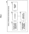
- FIG. 1 is a diagram illustrating a configuration of a vehicle approach notification device according to an embodiment.
- a vehicle approach notification device 100 illustrated in FIG. 1 is mounted on a vehicle (for example, an electric vehicle) that emits less noise, and outputs an artificial moving-car-like sound to the surroundings of the vehicle to notify pedestrians or the like in the vicinity of the vehicle of approach of the vehicle.
- the vehicle approach notification device 100 includes a moving-car-like sound generator 110, a speaker array 120, a speaker (SP) driver 130, a switching controller 140, and a surrounding situation determiner 150.
- SP speaker
- the moving-car-like sound generator 110 generates a predetermined sound for notifying pedestrians or the like in the vicinity of the vehicle of approach of the vehicle.
- the generated sound is assumed to be an artificial moving-car-like sound of a vehicle for a purpose of notifying approach of a vehicle by sound; therefore, the sound is not necessarily similar to a moving-car-like sound and may be a notification sound other than a moving-car-like sound.
- the speaker array 120 includes a plurality of speakers to which the generated sound that is output from the moving-car-like sound generator 110 is selectively input, and is set in the front portion of the vehicle.
- Each speaker is, for example, an ultrasonic speaker, and emits a sound in an audible band corresponding to the input generated sound.
- the speaker 122 reproduces audible sounds having narrow directivity by using waveform distortion caused by emitting two types of ultrasonic waves having a high sound pressure.
- one of the frequencies of the ultrasonic waves (carriers) is f1
- distortion components of 2f1, 3f1, 4f1, ..., which are integral multiples of f1 are generated.
- the other one of the frequencies of the ultrasonic waves (carriers) is f2, distortion components of 2f2, 3f2, 4f2, ..., which are integral multiples of f2, are generated.
- both of the frequencies f1 and f2 are ultrasonic waves (sounds of frequencies higher than the human audible band)
- the distortion of the integral multiples of these frequencies is also higher than the audible band, and the distortion is therefore not heard by the human ears.
- components of difference tones having a frequency of f2 - f1
- chords having a frequency of f1 + f2
- the frequency of the difference tones i.e., f2 - f1
- FIG. 2 is a diagram illustrating an embodiment of a configuration of the speaker array 120.
- the speaker array 120 of the present embodiment includes a total of 64 ultrasonic speakers 122 arranged in eight rows and eight columns, without any space therebetween.
- the SP driver 130 can selectively input a signal obtained by amplifying the sound generated by the moving-car-like sound generator 110 to one or a plurality of speakers 122 included in the speaker array 120, and thereby switches the width of the area in which one or a plurality of speakers 122 that radiate a sound are arranged by changing the selection state.
- the switching controller 140 instructs the SP driver 130 to switch the area (active area) that includes the speakers 122 radiating a sound in accordance with the width of the directivity of the sound output from the speaker array 120.
- the surrounding situation determiner 150 determines a surrounding situation. A switching instruction by the switching controller 140 is issued based on a surrounding situation determined by the surrounding situation determiner 150.
- the above-described moving-car-like sound generator 110 corresponds to an output sound generator
- the SP driver 130 corresponds to a speaker switcher
- the switching controller 140 corresponds to a switching instructor
- the surrounding situation determiner 150 corresponds to a surrounding situation determiner.
- the vehicle approach notification device 100 of the present embodiment has such a configuration, and an operation of switching directivity between a wide range and a narrow range is described hereinafter.
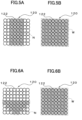
- FIGS. 3A and 3B are diagrams explaining a correspondence between the directivity and the speakers 122 to use.
- FIG. 3A illustrates an example of use of the speakers 122 in a case of widening directivity
- FIG. 3B illustrates an example of use of the speakers 122 in a case of narrowing directivity.
- FIGS. 4A and 4B are explanatory diagrams of a sound field when directivity is switched.
- wide directivity can be obtained by radiating a sound from a small number of speakers 122 included in the area N ( FIG. 3A )
- a sound is radiated from the speaker array 120 installed in the front portion of the vehicle toward a wide-range space.
- the sound is diffused at a large scale and is easily attenuated along the radiation direction, and thus pedestrians or the like in a short distance can hear the sound.
- directivity of the speaker array 120 is widened by using the speakers 122 included in a narrow area N among a plurality of speakers 122 constituting the speaker array 120, and directivity of the speaker array 120 is narrowed by using the speakers 122 included in a wide area; it is thus possible to switch the output range of a sound radiated from the speaker array 120 by switching the areas N and W where the speakers 122 are arranged.
- FIG. 5A is a diagram illustrating a modified example of the area N that is set in the speaker array 120.
- the area W having narrow directivity illustrated in FIG. 5B is the same as that illustrated in FIG. 3B .
- FIG. 6A is a diagram illustrating another modified example of the area N that is set in the speaker array 120.
- the area N having wide directivity illustrated in FIG. 6A has a trapezoidal shape with a short lower side and a long upper side, and includes a total of 20 speakers 122. Through radiation of a sound from these speakers 122, the directivity in a horizontal direction can be narrowed in the vicinity of the upper side where eight speakers 122 are arranged in the horizontal direction, and the directivity in the horizontal direction can be widened in the vicinity of the lower side where two speakers 122 are arranged in the horizontal direction.
- the area W having narrow directivity illustrated in FIG. 6B is the same as that illustrated in FIG. 3B .
- FIG. 7B is a diagram illustrating a modified example of the area W that is set in the speaker array 120.
- the area W having narrow directivity illustrated in FIG. 7B includes a total of 48 speakers 122 in two rows along the outer periphery. Through radiation of a sound from these speakers 122, the directivity can be narrowed similarly to the case illustrated in FIG. 3B .
- the area N having narrow directivity illustrated in FIG. 7A is the same as that illustrated in FIG. 3A .
- FIGS. 8A and 8B are diagrams illustrating another modified example of each of the areas N and W that is set in the speaker array 120.
- the directivity of the speaker array 120 can be widened by setting the central area N1 including the speakers 122 having high sound pressures, and the directivity of the speaker array 120 can be narrowed by setting the peripheral area W2 including the speakers 122 having high sound pressures.
- FIG. 9 is a diagram illustrating a specific example of a case where directivity of the speaker array 120 is switched in accordance with a traveling speed of a vehicle.
- the vehicle approach notification device 100A illustrated in FIG. 9 differs from the vehicle approach notification device 100 illustrated in FIG. 1 in that the surrounding situation determiner 150 is realized by a speed information acquirer 150A and the switching controller 140 is replaced with a switching controller 140A.
- the speed information acquirer 150A corresponds to a speed information acquirer.
- the speed information acquirer 150A acquires information of a traveling speed a vehicle.
- a traveling speed may be detected based on a vehicle speed pulse output at every predetermined traveling distance, or a traveling speed may be acquired from a vehicle controller or the like that performs a display operation of a speedometer or the like. Since a relative speed of a pedestrian or the like in the vicinity of the vehicle changes according to a traveling speed of the vehicle itself, a traveling speed of a vehicle is also considered as a "surrounding situation" in the present specification.
- the switching controller 140A instructs the SP driver 130 to select the area W so that directivity of a sound output from the speaker array 120 is narrowed when a traveling speed acquired by the speed information acquirer 150A is high, and to select the area N so that directivity of a sound output from the speaker array 120 is widened when a traveling speed acquired by the speed information acquirer 150A is low.
- the sound for informing the approach can be widely heard by pedestrians or the like in the vicinity of the vehicle, and when the vehicle travels at a medium speed or higher, the sound for informing presence of an approaching vehicle can be heard by pedestrians or the like who are present at a slightly distant place.
- FIG. 10 is a diagram illustrating a specific example of a case where directivity of the speaker array 120 is switched depending on whether a vehicle is traveling in an urban area or in a suburban area.
- the vehicle approach notification device 100B illustrated in FIG. 10 differs from the vehicle approach notification device 100 illustrated in FIG. 1 in that the surrounding situation determiner 150 is realized by a traveling environment determiner 150B and the switching controller 140 is replaced with a switching controller 140B.
- the traveling environment determiner 150B corresponds to a traveling environment determiner.
- the traveling environment determiner 150B determines whether a traveling position of the vehicle is in an urban area or a suburban area. For example, there may be a case where a vehicle navigation device that continuously or periodically determines whether the vehicle is located in an urban area or a suburban area is used as the traveling environment determiner 150B, or a case where the traveling environment determiner 150B obtains, from a vehicle navigation device, information indicating whether the vehicle is traveling in an urban area or a suburban area.
- the switching controller 140B instructs the SP driver 130 to select the area W so that directivity of a sound output from the speaker array 120 is narrowed in response to the traveling environment determiner 150B determining that the traveling position of the vehicle is in a suburban area, and to select the area N so that directivity of a sound output from the speaker array 120 is widened in response to the traveling environment determiner 150B determining that the traveling position of the vehicle is in an urban area.
- the pedestrians or the like in the vicinity of the vehicle as many as possible can be made to hear the sound for notifying approach of the vehicle, and in a suburban area where there are a relatively few people, the pedestrians or the like who are present at a slightly distant place can be made to hear the sound for notifying the pedestrians of the approach of the vehicle.
- FIG. 11 is a diagram illustrating a specific example of a case where a surrounding situation is determined based on an image obtained by imaging the surrounding.
- the vehicle approach notification device 100C illustrated in FIG. 11 differs from the vehicle approach notification device 100 illustrated in FIG. 1 in that the surrounding situation determiner 150 is realized by a camera 152 and an image analyzer 150C and in that the switching controller 140 is replaced with a switching controller 140C.
- the camera 152 corresponds to an imager
- the image analyzer 150C corresponds to an image analyzer.
- One or more cameras 152 are installed in a front portion or a side portion of the vehicle, and capture images of the surroundings including at least the front of the vehicle itself.
- the image analyzer 150C analyzes the situation around the vehicle itself such as the positions and the number of pedestrians present in the vicinity of the vehicle itself, the width of the traveling road, and the traveling lane, based on the image obtained through the imaging by the camera 152.
- the switching controller 140C instructs the SP driver 130 to switch between the area W in which directivity of a sound output from the speaker array 120 is narrowed and the area N in which directivity of a sound output from the speaker array 120 is widened, based on a situation around the vehicle itself analyzed by the image analyzer 150C.
- the area N in which directivity is widened is selected, and in the case where there are no pedestrians or the like, the area W in which the directivity is narrowed is selected.
- the captured image may be analyzed to perform the same processing as that of the speed information acquirer 150A illustrated in FIG. 9 or the same processing as that of the traveling environment determiner 150B illustrated in FIG. 10 .
- FIG. 12 is a diagram illustrating a modified example in which directivity of the speaker array 120 is varied according to a congestion state of a room.
- the announcement device 100D illustrated in FIG. 12 is installed in a sales area of a department store, for example, and radiates a predetermined announcement sound to some customers.
- the announcement device 100D has a configuration similar to that of the vehicle approach notification device 100 illustrated in FIG. 1 , and differs from the vehicle approach notification device 100 in that the surrounding situation determiner 150 is realized by a congestion state determiner 150D, the moving-car-like sound generator 110 is replaced with an announcement sound generator 110D, and the switching controller 140 is replaced with a switching controller 140D.
- the announcement sound generator 110D corresponds to an output sound generator
- the congestion state determiner 150D corresponds to a congestion state determiner.
- the congestion state determiner 150D determines the congestion state of customers in the vicinity (a specific area in the department store). This determination may be made by analyzing an image captured by the camera 152 as in the image analyzer 150C illustrated in FIG. 11 , or may be made based on a detection result of a sensor provided at the entrance/exit for detecting the entrance/exit of a customer.
- the switching controller 140D instructs the SP driver 130 to switch between the area W in which directivity of a sound output from the speaker array 120 is narrowed and the area N in which directional characteristics of a sound output from the speaker array 120 is widened, based on a congestion state around the vehicle itself analyzed by the congestion state determiner 150D.
- the area N in which directivity of an announcement sound to be radiated is widened is selected in order to attract customers; in the case where the number of customers in a specific area is large in a congested state, on the other hand, the area w in which directivity of an announcement sound to be radiated is narrowed is selected in order to make only intended customers hear the announcement.
- This allows the speaker system to switch directivity of a sound radiated from the speaker array 120 between a wide range and a narrow range in accordance with a congestion state of the surroundings.
- the announcement device 100D illustrated in FIG. 12 can be used for announcement sounds other than an announcement sound of a department store. For example, in a museum, when many students are present in an exhibition room and the exhibition room is crowded due to there being a student tour or the like, the area N in which directivity of an announcement sound to be radiated is widened is selected, and in other cases, the area W in which directivity of an announcement sound to be radiated is narrowed is selected.
- the present disclosure is not limited to the above-described embodiment, and various modifications can be made within the scope of the present disclosure.
- either wide directivity corresponding to the area N or narrow directivity corresponding to the area W is selected; however, the area N and the area W may be alternately switched at predetermined time intervals to repeat wide directivity and narrow directivity of a sound radiated from the speaker array 120. This allows a sound radiated from the speaker array 120 to be heard in both the near and distant spaces around the vehicle.
- the speaker array 120 is configured using the ultrasonic speakers 122; however, the speaker array 120 may be configured using speakers other than ultrasonic speakers (speakers that directly output sound in the audible band).
Landscapes
- Physics & Mathematics (AREA)
- Engineering & Computer Science (AREA)
- Acoustics & Sound (AREA)
- Signal Processing (AREA)
- Health & Medical Sciences (AREA)
- Otolaryngology (AREA)
- General Health & Medical Sciences (AREA)
- Circuit For Audible Band Transducer (AREA)
Abstract
Description
- The present disclosure relates to a speaker system in which a plurality of speakers are combined.
- A vehicle presence notification device is known that uses a speaker array in which a plurality of ultrasonic speakers are combined, and is configured to change the directivity of a notification sound by adjusting a phase of a sound wave that is output from each ultrasonic speaker to (for example, see
JP 2011-31695 A - The present disclosure relates to a speaker system according to the appended claims. Embodiments are disclosed in the dependent claims. According to an embodiment of the present disclosure, a speaker system includes an output sound generator configured to generate a sound to be output, a speaker array including a plurality of speakers to which the sound generated by the output sound generator can be selectively input, a speaker switcher configured to switch one or more speakers to which the generated sound is input, and a switching instructor configured to instruct the speaker switcher in accordance with a width of directivity of a sound that is output from the speaker array.
-
FIG. 1 is a diagram illustrating a configuration of a vehicle approach notification device according to an embodiment; -
FIG. 2 is a diagram illustrating an exemplary configuration of a speaker array; -
FIGS. 3A and 3B are exemplary diagrams explaining a correspondence between a width of directivity and speakers to use; -
FIGS. 4A and 4B are explanatory diagrams of a sound field when directivity is switched; -
FIG. 5A is a diagram illustrating a modified example of an area N that is set in the speaker array; -
FIG. 5B is a diagram illustrating the same area W as illustrated inFIG. 3B ; -
FIG. 6A is a diagram illustrating another modified example of an area N that is set in the speaker array; -
FIG. 6B is a diagram illustrating the same area W as illustrated inFIG. 3B ; -
FIG. 7A is a diagram illustrating the same area N as illustrated inFIG. 3A ; -
FIG. 7B is a diagram illustrating a modified example of an area W that is set in the speaker array; -
FIG. 8A is a diagram illustrating another modified example of the area N that is set in the speaker array; -
FIG. 8B is a diagram illustrating another modified example of the area W that is set in the speaker array; -
FIG. 9 is a diagram illustrating a specific example of a case where directivity of the speaker array is switched in accordance with a traveling speed of a vehicle; -
FIG. 10 is a diagram illustrating a specific example of a case where directivity of the speaker array is switched depending on whether a vehicle is traveling in an urban area or in a suburban area; -
FIG. 11 is a diagram illustrating a specific example of a case where a surrounding situation is determined based on an image obtained by imaging the surrounding; and -
FIG. 12 is a diagram illustrating a modified example in which directivity of the speaker array is varied according to a congestion state of a room. - The above-described vehicle presence notification device disclosed in
JP 2011-31695 A - The present disclosure has been made in view of the above circumstances and provides a speaker system capable of switching an output range of sound.
- A speaker system according to an aspect of the present disclosure includes an output sound generator for generating a sound to be output, a speaker array including a plurality of speakers to which the sound generated by the output sound generator can be selectively input, a speaker switcher for switching one or a plurality of speakers to which the generated sound is input, and a switching instructor for instructing the speaker switcher to switch in accordance with a directivity of a sound output from the speaker array. Particularly, the speaker switcher selectively switches between a first area having a large area and a large number of speakers and a second area having a small area and a small number of speakers.
- Using the speakers included in the small area among a plurality of speakers constituting the speaker array widens the directivity of the speaker array, and using the speakers included in the large area narrows the directivity of the speaker array, and thus it is possible to switch the output range of a sound radiated from the speaker array by switching the area where the speakers are arranged.
- Furthermore, it is preferable that the speaker system further includes a surrounding situation determiner and the switching instructor instructs the speaker switcher to switch the directivity based on a determination made by the surrounding situation determiner. Thus, directivity can be automatically switched between a wide range and a narrow range in accordance with a surrounding situation.
- It is preferable that the speaker system is mounted on a vehicle and configured to output a sound that notifies people in the vicinity of the vehicle of approach of the vehicle, that the surrounding situation determiner is a speed information acquirer for acquiring a traveling speed of a vehicle, and that the switching instructor instructs the speaker switcher to select between a first area in a case of a high traveling speed so that the directivity of a sound output from the speaker array becomes narrow and a second area in a case of a low traveling speed so that the directivity becomes wide. Thus, when the vehicle travels at a low speed, the sound for informing the approach can be widely heard by pedestrians or the like in the vicinity of the vehicle, and when the vehicle travels at a medium speed or higher, the sound for informing presence of an approaching vehicle can be heard by pedestrians or the like who are present at a slightly distant place.
- It is preferable that the speaker system is mounted on a vehicle and configured to output a sound notifying people in the vicinity of the vehicle of approach of the vehicle, that the surrounding situation determiner is a traveling environment determiner for determining whether the vehicle is traveling is in an urban area or in a suburban area, and the switching instructor instructs the speaker switcher to select, in a case of determining the traveling position of the vehicle to be a suburban area, a first area to narrow the directivity of a sound to be output from the speaker array, and in a case of determining the traveling position of the vehicle to be an urban area, select the second area to widen the directivity of a sound to be output from the speaker array. Thus, in an urban area where there is a high possibility that many pedestrians or the like are present in the vicinity of the vehicle, the pedestrians or the like in the vicinity of the vehicle as many as possible can be made to hear the sound for notifying the pedestrians of the approach, and in a suburban area where there are a relatively few people, the pedestrians or the like who are present at a slightly distant place can be made to hear the sound for notifying the pedestrians of the approach.
- It is preferable that the switching instructor instructs the speaker switcher to alternately select the first area and the second area. This allows a sound radiated from the speaker array to be heard in both the near and distant spaces around the vehicle.
- It is preferable that the surrounding situation determiner includes an imager for imaging the surrounding and an image analyzer for analyzing a surrounding situation based on the image obtained by the imager, and the switching instructor instructs the speaker switcher to select either the first area or the second area based on the surrounding situation analyzed by the image analyzer. This allows the speaker system to ascertain a surrounding situation accurately and to switch the directivity of the sound radiated from the speaker array between a wide range and a narrow range.
- It is preferable that the surrounding situation determiner is a congestion state determiner for determining a congestion state of the surroundings, and the switching instructor instructs the speaker switcher to select either the first area or the second area based on the congestion state of the surroundings determined by the congestion state determiner. This allows the speaker system to switch the directivity of the sound radiated from the speaker array between a wide range and a narrow range in accordance with a congestion state of the surroundings.
- Hereinafter, a vehicle approach notification device according to embodiments to which a speaker system of the present disclosure is applied will be described with reference to the drawings.
-
FIG. 1 is a diagram illustrating a configuration of a vehicle approach notification device according to an embodiment. A vehicleapproach notification device 100 illustrated inFIG. 1 is mounted on a vehicle (for example, an electric vehicle) that emits less noise, and outputs an artificial moving-car-like sound to the surroundings of the vehicle to notify pedestrians or the like in the vicinity of the vehicle of approach of the vehicle. For this purpose, the vehicleapproach notification device 100 includes a moving-car-like sound generator 110, aspeaker array 120, a speaker (SP)driver 130, aswitching controller 140, and a surrounding situation determiner 150. - The moving-car-
like sound generator 110 generates a predetermined sound for notifying pedestrians or the like in the vicinity of the vehicle of approach of the vehicle. The generated sound is assumed to be an artificial moving-car-like sound of a vehicle for a purpose of notifying approach of a vehicle by sound; therefore, the sound is not necessarily similar to a moving-car-like sound and may be a notification sound other than a moving-car-like sound. - The
speaker array 120 includes a plurality of speakers to which the generated sound that is output from the moving-car-like sound generator 110 is selectively input, and is set in the front portion of the vehicle. Each speaker is, for example, an ultrasonic speaker, and emits a sound in an audible band corresponding to the input generated sound. - The speaker 122 (
FIG. 2 ) reproduces audible sounds having narrow directivity by using waveform distortion caused by emitting two types of ultrasonic waves having a high sound pressure. When one of the frequencies of the ultrasonic waves (carriers) is f1, distortion components of 2f1, 3f1, 4f1, ..., which are integral multiples of f1, are generated. When the other one of the frequencies of the ultrasonic waves (carriers) is f2, distortion components of 2f2, 3f2, 4f2, ..., which are integral multiples of f2, are generated. In the case where both of the frequencies f1 and f2 are ultrasonic waves (sounds of frequencies higher than the human audible band), the distortion of the integral multiples of these frequencies is also higher than the audible band, and the distortion is therefore not heard by the human ears. However, in the case where ultrasonic waves of such two kinds of carriers are simultaneously radiated, components of difference tones (having a frequency of f2 - f1) and chords (having a frequency of f1 + f2) are generated. By setting the frequency of the difference tones (i.e., f2 - f1) to be within the audible band, the generated sound as an audible sound can be radiated from theultrasonic speaker 122. For example, suppose f1 is 41 kHz and f2 is 40 kHz, it is possible to radiate a difference tone of f2 - f1 = 1 kHz. -
FIG. 2 is a diagram illustrating an embodiment of a configuration of thespeaker array 120. As illustrated inFIG. 2 , thespeaker array 120 of the present embodiment includes a total of 64ultrasonic speakers 122 arranged in eight rows and eight columns, without any space therebetween. - The
SP driver 130 can selectively input a signal obtained by amplifying the sound generated by the moving-car-like sound generator 110 to one or a plurality ofspeakers 122 included in thespeaker array 120, and thereby switches the width of the area in which one or a plurality ofspeakers 122 that radiate a sound are arranged by changing the selection state. - The switching
controller 140 instructs theSP driver 130 to switch the area (active area) that includes thespeakers 122 radiating a sound in accordance with the width of the directivity of the sound output from thespeaker array 120. - The surrounding
situation determiner 150 determines a surrounding situation. A switching instruction by the switchingcontroller 140 is issued based on a surrounding situation determined by the surroundingsituation determiner 150. - The above-described moving-car-
like sound generator 110 corresponds to an output sound generator, theSP driver 130 corresponds to a speaker switcher, the switchingcontroller 140 corresponds to a switching instructor, and the surroundingsituation determiner 150 corresponds to a surrounding situation determiner. - The vehicle
approach notification device 100 of the present embodiment has such a configuration, and an operation of switching directivity between a wide range and a narrow range is described hereinafter. -
FIGS. 3A and 3B are diagrams explaining a correspondence between the directivity and thespeakers 122 to use.FIG. 3A illustrates an example of use of thespeakers 122 in a case of widening directivity, andFIG. 3B illustrates an example of use of thespeakers 122 in a case of narrowing directivity. - In order to widen directivity, it is necessary to reduce the number of
speakers 122 that radiate a sound and to narrow the area where thespeakers 122 are arranged. InFIG. 3A , a small number (4 × 4 = 16 at the center) ofspeakers 122 included in the narrow area N (second area) are selected, and a sound is radiated from these 16speakers 122. - In order to narrow directivity, it is necessary to increase the number of
speakers 122 that radiate a sound and to widen the area where thespeakers 122 are arranged. InFIG. 3B , a large number (8 × 8 = 64 at the center) ofspeakers 122 included in the wide area W (first area) are selected, and a sound is radiated from these 64speakers 122. -
FIGS. 4A and 4B are explanatory diagrams of a sound field when directivity is switched. As illustrated inFIG. 4A , since wide directivity can be obtained by radiating a sound from a small number ofspeakers 122 included in the area N (FIG. 3A ), a sound is radiated from thespeaker array 120 installed in the front portion of the vehicle toward a wide-range space. In this case, the sound is diffused at a large scale and is easily attenuated along the radiation direction, and thus pedestrians or the like in a short distance can hear the sound. - As illustrated in
FIG. 4B , on the other hand, since narrow directivity can be obtained by radiating sound from a large number ofspeakers 122 included in the area W (FIG. 3B ), a sound is radiated from thespeaker array 120 installed in the front portion of the vehicle toward a narrow-range space. In this case, the sound is diffused at a small scale and is less easily attenuated along the radiation direction, and thus pedestrians or the like in a distant area can hear the sound. - Thus, directivity of the
speaker array 120 is widened by using thespeakers 122 included in a narrow area N among a plurality ofspeakers 122 constituting thespeaker array 120, and directivity of thespeaker array 120 is narrowed by using thespeakers 122 included in a wide area; it is thus possible to switch the output range of a sound radiated from thespeaker array 120 by switching the areas N and W where thespeakers 122 are arranged. -
FIG. 5A is a diagram illustrating a modified example of the area N that is set in thespeaker array 120. The area N having wide directivity illustrated inFIG. 5B includes 8 × 4 = 32speakers 122. Through radiation of a sound from thesespeakers 122, the directivity in a horizontal direction can be widened and the directivity in a vertical direction can be narrowed. The area W having narrow directivity illustrated inFIG. 5B is the same as that illustrated inFIG. 3B . -
FIG. 6A is a diagram illustrating another modified example of the area N that is set in thespeaker array 120. The area N having wide directivity illustrated inFIG. 6A has a trapezoidal shape with a short lower side and a long upper side, and includes a total of 20speakers 122. Through radiation of a sound from thesespeakers 122, the directivity in a horizontal direction can be narrowed in the vicinity of the upper side where eightspeakers 122 are arranged in the horizontal direction, and the directivity in the horizontal direction can be widened in the vicinity of the lower side where twospeakers 122 are arranged in the horizontal direction. The area W having narrow directivity illustrated inFIG. 6B is the same as that illustrated inFIG. 3B . -
FIG. 7B is a diagram illustrating a modified example of the area W that is set in thespeaker array 120. The area W having narrow directivity illustrated inFIG. 7B includes a total of 48speakers 122 in two rows along the outer periphery. Through radiation of a sound from thesespeakers 122, the directivity can be narrowed similarly to the case illustrated inFIG. 3B . The area N having narrow directivity illustrated inFIG. 7A is the same as that illustrated inFIG. 3A . -
FIGS. 8A and 8B are diagrams illustrating another modified example of each of the areas N and W that is set in thespeaker array 120. The areas N1 and N2 illustrated inFIG. 8A having wide directivity include a total of 8 × 8 = 64speakers 122, and among these, 4 × 4 = 16speakers 122 in the central area N1 have high sound pressures, and 48speakers 122 in the peripheral area N2 have low sound pressures. The areas W1 and W2 illustrated inFIG. 8B having narrow directivity include a total of 8 × 8 = 64speakers 122, and among these, 4 × 4 = 16speakers 122 in the central area W1 have low sound pressures, and 48speakers 122 in the peripheral area W2 have high sound pressures. As described above, even when the number ofspeakers 122 to be used is the same, the directivity of thespeaker array 120 can be widened by setting the central area N1 including thespeakers 122 having high sound pressures, and the directivity of thespeaker array 120 can be narrowed by setting the peripheral area W2 including thespeakers 122 having high sound pressures. - Next, a specific example of the surrounding
situation determiner 150 will be described. -
FIG. 9 is a diagram illustrating a specific example of a case where directivity of thespeaker array 120 is switched in accordance with a traveling speed of a vehicle. The vehicleapproach notification device 100A illustrated inFIG. 9 differs from the vehicleapproach notification device 100 illustrated inFIG. 1 in that the surroundingsituation determiner 150 is realized by aspeed information acquirer 150A and the switchingcontroller 140 is replaced with a switchingcontroller 140A. Thespeed information acquirer 150A corresponds to a speed information acquirer. - The
speed information acquirer 150A acquires information of a traveling speed a vehicle. For example, a traveling speed may be detected based on a vehicle speed pulse output at every predetermined traveling distance, or a traveling speed may be acquired from a vehicle controller or the like that performs a display operation of a speedometer or the like. Since a relative speed of a pedestrian or the like in the vicinity of the vehicle changes according to a traveling speed of the vehicle itself, a traveling speed of a vehicle is also considered as a "surrounding situation" in the present specification. - The switching
controller 140A instructs theSP driver 130 to select the area W so that directivity of a sound output from thespeaker array 120 is narrowed when a traveling speed acquired by thespeed information acquirer 150A is high, and to select the area N so that directivity of a sound output from thespeaker array 120 is widened when a traveling speed acquired by thespeed information acquirer 150A is low. - Thus, when the vehicle travels at a low speed, the sound for informing the approach can be widely heard by pedestrians or the like in the vicinity of the vehicle, and when the vehicle travels at a medium speed or higher, the sound for informing presence of an approaching vehicle can be heard by pedestrians or the like who are present at a slightly distant place.
-
FIG. 10 is a diagram illustrating a specific example of a case where directivity of thespeaker array 120 is switched depending on whether a vehicle is traveling in an urban area or in a suburban area. The vehicleapproach notification device 100B illustrated inFIG. 10 differs from the vehicleapproach notification device 100 illustrated inFIG. 1 in that the surroundingsituation determiner 150 is realized by a travelingenvironment determiner 150B and the switchingcontroller 140 is replaced with a switchingcontroller 140B. The travelingenvironment determiner 150B corresponds to a traveling environment determiner. - The traveling
environment determiner 150B determines whether a traveling position of the vehicle is in an urban area or a suburban area. For example, there may be a case where a vehicle navigation device that continuously or periodically determines whether the vehicle is located in an urban area or a suburban area is used as the travelingenvironment determiner 150B, or a case where the travelingenvironment determiner 150B obtains, from a vehicle navigation device, information indicating whether the vehicle is traveling in an urban area or a suburban area. - The switching
controller 140B instructs theSP driver 130 to select the area W so that directivity of a sound output from thespeaker array 120 is narrowed in response to the travelingenvironment determiner 150B determining that the traveling position of the vehicle is in a suburban area, and to select the area N so that directivity of a sound output from thespeaker array 120 is widened in response to the travelingenvironment determiner 150B determining that the traveling position of the vehicle is in an urban area. - Thus, in an urban area where there is a high possibility that many pedestrians or the like are present in the vicinity of the vehicle, the pedestrians or the like in the vicinity of the vehicle as many as possible can be made to hear the sound for notifying approach of the vehicle, and in a suburban area where there are a relatively few people, the pedestrians or the like who are present at a slightly distant place can be made to hear the sound for notifying the pedestrians of the approach of the vehicle.
-
FIG. 11 is a diagram illustrating a specific example of a case where a surrounding situation is determined based on an image obtained by imaging the surrounding. The vehicleapproach notification device 100C illustrated inFIG. 11 differs from the vehicleapproach notification device 100 illustrated inFIG. 1 in that the surroundingsituation determiner 150 is realized by acamera 152 and animage analyzer 150C and in that the switchingcontroller 140 is replaced with a switchingcontroller 140C. Thecamera 152 corresponds to an imager, and theimage analyzer 150C corresponds to an image analyzer. - One or
more cameras 152 are installed in a front portion or a side portion of the vehicle, and capture images of the surroundings including at least the front of the vehicle itself. Theimage analyzer 150C analyzes the situation around the vehicle itself such as the positions and the number of pedestrians present in the vicinity of the vehicle itself, the width of the traveling road, and the traveling lane, based on the image obtained through the imaging by thecamera 152. - The switching
controller 140C instructs theSP driver 130 to switch between the area W in which directivity of a sound output from thespeaker array 120 is narrowed and the area N in which directivity of a sound output from thespeaker array 120 is widened, based on a situation around the vehicle itself analyzed by theimage analyzer 150C. - For example, as a result of analyzing the image, in the case where there are many pedestrians or the like in the vicinity of the vehicle, the area N in which directivity is widened is selected, and in the case where there are no pedestrians or the like, the area W in which the directivity is narrowed is selected. This allows the speaker system to ascertain a surrounding situation accurately and to switch the directivity of a sound radiated from the
speaker array 120 between a wide range and a narrow range. The captured image may be analyzed to perform the same processing as that of thespeed information acquirer 150A illustrated inFIG. 9 or the same processing as that of the travelingenvironment determiner 150B illustrated inFIG. 10 . -
FIG. 12 is a diagram illustrating a modified example in which directivity of thespeaker array 120 is varied according to a congestion state of a room. Theannouncement device 100D illustrated inFIG. 12 is installed in a sales area of a department store, for example, and radiates a predetermined announcement sound to some customers. Theannouncement device 100D has a configuration similar to that of the vehicleapproach notification device 100 illustrated inFIG. 1 , and differs from the vehicleapproach notification device 100 in that the surroundingsituation determiner 150 is realized by acongestion state determiner 150D, the moving-car-like sound generator 110 is replaced with anannouncement sound generator 110D, and the switchingcontroller 140 is replaced with a switchingcontroller 140D. Theannouncement sound generator 110D corresponds to an output sound generator, and thecongestion state determiner 150D corresponds to a congestion state determiner. - The
congestion state determiner 150D determines the congestion state of customers in the vicinity (a specific area in the department store). This determination may be made by analyzing an image captured by thecamera 152 as in theimage analyzer 150C illustrated inFIG. 11 , or may be made based on a detection result of a sensor provided at the entrance/exit for detecting the entrance/exit of a customer. - The switching
controller 140D instructs theSP driver 130 to switch between the area W in which directivity of a sound output from thespeaker array 120 is narrowed and the area N in which directional characteristics of a sound output from thespeaker array 120 is widened, based on a congestion state around the vehicle itself analyzed by thecongestion state determiner 150D. - For example, in the case where the number of customers in a specific area is small in a non-congested state, the area N in which directivity of an announcement sound to be radiated is widened is selected in order to attract customers; in the case where the number of customers in a specific area is large in a congested state, on the other hand, the area w in which directivity of an announcement sound to be radiated is narrowed is selected in order to make only intended customers hear the announcement. This allows the speaker system to switch directivity of a sound radiated from the
speaker array 120 between a wide range and a narrow range in accordance with a congestion state of the surroundings. - The
announcement device 100D illustrated inFIG. 12 can be used for announcement sounds other than an announcement sound of a department store. For example, in a museum, when many students are present in an exhibition room and the exhibition room is crowded due to there being a student tour or the like, the area N in which directivity of an announcement sound to be radiated is widened is selected, and in other cases, the area W in which directivity of an announcement sound to be radiated is narrowed is selected. - The present disclosure is not limited to the above-described embodiment, and various modifications can be made within the scope of the present disclosure. In the above-described embodiment, either wide directivity corresponding to the area N or narrow directivity corresponding to the area W is selected; however, the area N and the area W may be alternately switched at predetermined time intervals to repeat wide directivity and narrow directivity of a sound radiated from the
speaker array 120. This allows a sound radiated from thespeaker array 120 to be heard in both the near and distant spaces around the vehicle. - In the above-described embodiment, the
speaker array 120 is configured using theultrasonic speakers 122; however, thespeaker array 120 may be configured using speakers other than ultrasonic speakers (speakers that directly output sound in the audible band). - As described above, according to the present disclosure, using speakers included in a small area among a plurality of speakers constituting a speaker array would widen directivity of the speaker array, and using speakers included in a large area would narrow directivity of the speaker array; it is thus possible to switch the output range of a sound radiated from the speaker array by switching the area where the speakers are arranged.
Claims (8)
- A speaker system, comprising:an output sound generator configured to generate a sound to be output;a speaker array including a plurality of speakers to which the sound generated by the output sound generator can be selectively input;a speaker switcher configured to switch one or more speakers to which the generated sound is input; anda switching instructor configured to instruct the speaker switcher in accordance with a width of directivity of a sound that is to be output from the speaker array.
- The speaker system according to claim 1, wherein
the speaker switcher is configured to selectively switch between a first area having a large area and a large number of speakers and a second area having a small area and a small number of speakers. - The speaker system according to claim 1 or 2, further comprising:a surrounding situation determiner configured to determine a situation of surrounding, whereinthe switching instructor is configured to perform a switching instruction based on the situation of surrounding determined by the surrounding situation determiner.
- The speaker system according to claim 3, whereinthe speaker system is mounted on a vehicle and configured to output a sound for notifying people in the vicinity of the vehicle of approach of the vehicle,the surrounding situation determiner is a speed information acquirer configured to acquire a traveling speed of the vehicle, andthe switching instructor is configured to perform a switching instruction to select the first area so that directivity of a sound output from the speaker array is narrowed when the traveling speed acquired by the speed information acquirer is high, and to select the second area so that directivity of a sound output from the speaker array is widened when the traveling speed acquired by the speed information acquirer is low.
- The speaker system according to claim 3 or 4, whereinthe speaker system is mounted on a vehicle and configured to output a sound for notifying people in the vicinity of the vehicle of approach of the vehicle,the surrounding situation determiner is a traveling environment determiner configured to determine whether a traveling position of the vehicle is in an urban area or in a suburban area, andthe switching instructor is configured to instruct the speaker switcher to select, in a case of the traveling environment determiner determining that the traveling position of the vehicle is in a suburban area, the first area so that directivity of a sound output from the speaker array is narrowed, and select, in a case of the traveling environment determiner determining that the traveling position of the vehicle is in an urban area, the second area so that the directivity of a sound output from the speaker array is widened.
- The speaker system according to one of claims 2 - 5, wherein
the switching instructor is configured to instruct a switching to alternately select the first area and the second area. - The speaker system according to one of claims 3 - 6,the surrounding situation determiner includes an imager configured to capture an image of surroundings and an image analyzer configured to analyze a situation of surrounding based on the image captured by the imager, andthe switching instructor is configured to instruct the speaker switcher to select one of the first area or the second area based on the situation of surrounding analyzed by the image analyzer.
- The speaker system according to one of claims 3 - 7,the surrounding situation determiner is a congestion state determiner configured to determine a congestion state of surroundings, andthe switching instructor is configured to instruct the speaker switcher to select one of the first area or the second area based on the congestion state of the surroundings determined by the congestion state determiner.
Applications Claiming Priority (1)
| Application Number | Priority Date | Filing Date | Title |
|---|---|---|---|
| JP2023198899A JP2025085191A (en) | 2023-11-24 | 2023-11-24 | Speaker System |
Publications (2)
| Publication Number | Publication Date |
|---|---|
| EP4561105A2 true EP4561105A2 (en) | 2025-05-28 |
| EP4561105A3 EP4561105A3 (en) | 2025-08-06 |
Family
ID=93563634
Family Applications (1)
| Application Number | Title | Priority Date | Filing Date |
|---|---|---|---|
| EP24213379.1A Pending EP4561105A3 (en) | 2023-11-24 | 2024-11-15 | Speaker system |
Country Status (4)
| Country | Link |
|---|---|
| US (1) | US20250175738A1 (en) |
| EP (1) | EP4561105A3 (en) |
| JP (1) | JP2025085191A (en) |
| CN (1) | CN120050578A (en) |
Citations (1)
| Publication number | Priority date | Publication date | Assignee | Title |
|---|---|---|---|---|
| JP2011031695A (en) | 2009-07-30 | 2011-02-17 | Denso Corp | Vehicle presence informing device |
Family Cites Families (13)
| Publication number | Priority date | Publication date | Assignee | Title |
|---|---|---|---|---|
| US8849185B2 (en) * | 2003-04-15 | 2014-09-30 | Ipventure, Inc. | Hybrid audio delivery system and method therefor |
| JP5821172B2 (en) * | 2010-09-14 | 2015-11-24 | ヤマハ株式会社 | Speaker device |
| JP5338872B2 (en) * | 2011-08-02 | 2013-11-13 | 株式会社デンソー | Vehicle presence notification device |
| JP2013146051A (en) * | 2011-12-15 | 2013-07-25 | Tei Co Ltd | Speaker system |
| WO2017070262A1 (en) * | 2015-10-20 | 2017-04-27 | Alwin Co., Ltd. | Transducer module and sound delivery device having same |
| CN108370482B (en) * | 2015-12-18 | 2020-07-28 | 杜比实验室特许公司 | Dual Directional Speakers for Immersive Audio Content |
| EP3484184A4 (en) * | 2016-07-05 | 2019-06-19 | Sony Corporation | ACOUSTIC FIELD FORMING DEVICE, METHOD, AND PROGRAM |
| US9981602B2 (en) * | 2016-08-19 | 2018-05-29 | 2236008 Ontario Inc. | System and method for pedestrian alert |
| EP3519846B1 (en) * | 2016-09-29 | 2023-03-22 | Dolby Laboratories Licensing Corporation | Automatic discovery and localization of speaker locations in surround sound systems |
| JP2019047414A (en) * | 2017-09-06 | 2019-03-22 | 株式会社デンソー | Ultrasonic output device and pronunciation control method |
| US10315563B1 (en) * | 2018-05-22 | 2019-06-11 | Zoox, Inc. | Acoustic notifications |
| US10511906B1 (en) * | 2018-06-22 | 2019-12-17 | EVA Automation, Inc. | Dynamically adapting sound based on environmental characterization |
| KR20230111619A (en) * | 2022-01-17 | 2023-07-26 | 현대자동차주식회사 | Driver asistance apparatus, control method thereof and vehicle |
-
2023
- 2023-11-24 JP JP2023198899A patent/JP2025085191A/en active Pending
-
2024
- 2024-10-29 US US18/930,163 patent/US20250175738A1/en active Pending
- 2024-11-15 EP EP24213379.1A patent/EP4561105A3/en active Pending
- 2024-11-18 CN CN202411642660.XA patent/CN120050578A/en active Pending
Patent Citations (1)
| Publication number | Priority date | Publication date | Assignee | Title |
|---|---|---|---|---|
| JP2011031695A (en) | 2009-07-30 | 2011-02-17 | Denso Corp | Vehicle presence informing device |
Also Published As
| Publication number | Publication date |
|---|---|
| EP4561105A3 (en) | 2025-08-06 |
| JP2025085191A (en) | 2025-06-05 |
| US20250175738A1 (en) | 2025-05-29 |
| CN120050578A (en) | 2025-05-27 |
Similar Documents
| Publication | Publication Date | Title |
|---|---|---|
| US12425538B2 (en) | Focused sound and infotainment system and method | |
| US9875410B2 (en) | Camera system for transmitting and receiving an audio signal and operating method of the same | |
| US8817578B2 (en) | Sonic wave output device, voice communication device, sonic wave output method and program | |
| US7760891B2 (en) | Focused hypersonic communication | |
| Xia et al. | Improving pedestrian safety in cities using intelligent wearable systems | |
| EP3582511A2 (en) | Directional sound modification | |
| JP5235070B2 (en) | Sound monitoring device | |
| JP2017143357A (en) | Wireless audio system, controller, wireless speaker, and computer readable program | |
| EP3997481B1 (en) | Intelligent beam forming for a range detection device of a vehicle | |
| US20190124446A1 (en) | Methods, systems, and computer readable media for a phase array directed speaker | |
| KR101793942B1 (en) | Apparatus for tracking sound source using sound receiving device and method thereof | |
| JP2010232888A (en) | Monitoring device | |
| JPWO2018101082A1 (en) | Radar equipment | |
| US20250175738A1 (en) | Speaker system | |
| CN105245996A (en) | Instrument with remote object detection unit | |
| KR20220128959A (en) | Test system for LID sensor and method for testing LRA sensor | |
| US9491396B2 (en) | Apparatus, method, and system of controlling projection image, and recording medium storing image projection control program | |
| JP2008113190A (en) | Audible sound directivity control device | |
| JP6131752B2 (en) | Vehicle ambient environment notification system | |
| JP2005159446A (en) | Directional acoustic system | |
| EP4561104A1 (en) | Speaker system | |
| KR20130076495A (en) | Directional speaker apparatus capable of visually indicating acoustic space | |
| WO2020008685A1 (en) | Information notification device, program for information notification device, and information notification system | |
| US20200393251A1 (en) | Indoor navigation | |
| JP4297026B2 (en) | Object detection method and object detection apparatus |
Legal Events
| Date | Code | Title | Description |
|---|---|---|---|
| PUAI | Public reference made under article 153(3) epc to a published international application that has entered the european phase |
Free format text: ORIGINAL CODE: 0009012 |
|
| STAA | Information on the status of an ep patent application or granted ep patent |
Free format text: STATUS: THE APPLICATION HAS BEEN PUBLISHED |
|
| AK | Designated contracting states |
Kind code of ref document: A2 Designated state(s): AL AT BE BG CH CY CZ DE DK EE ES FI FR GB GR HR HU IE IS IT LI LT LU LV MC ME MK MT NL NO PL PT RO RS SE SI SK SM TR |
|
| PUAL | Search report despatched |
Free format text: ORIGINAL CODE: 0009013 |
|
| AK | Designated contracting states |
Kind code of ref document: A3 Designated state(s): AL AT BE BG CH CY CZ DE DK EE ES FI FR GB GR HR HU IE IS IT LI LT LU LV MC ME MK MT NL NO PL PT RO RS SE SI SK SM TR |
|
| RIC1 | Information provided on ipc code assigned before grant |
Ipc: H04R 1/40 20060101AFI20250701BHEP Ipc: H04R 3/12 20060101ALI20250701BHEP Ipc: B60Q 5/00 20060101ALI20250701BHEP Ipc: B60R 21/00 20060101ALI20250701BHEP |
|
| STAA | Information on the status of an ep patent application or granted ep patent |
Free format text: STATUS: REQUEST FOR EXAMINATION WAS MADE |
|
| 17P | Request for examination filed |
Effective date: 20260203 |