EP4560964A1 - Dmrs-portanzeigeverfahren und -vorrichtung sowie speichermedium - Google Patents
Dmrs-portanzeigeverfahren und -vorrichtung sowie speichermedium Download PDFInfo
- Publication number
- EP4560964A1 EP4560964A1 EP23851573.8A EP23851573A EP4560964A1 EP 4560964 A1 EP4560964 A1 EP 4560964A1 EP 23851573 A EP23851573 A EP 23851573A EP 4560964 A1 EP4560964 A1 EP 4560964A1
- Authority
- EP
- European Patent Office
- Prior art keywords
- dmrs
- value
- antenna port
- mapped
- antenna
- Prior art date
- Legal status (The legal status is an assumption and is not a legal conclusion. Google has not performed a legal analysis and makes no representation as to the accuracy of the status listed.)
- Pending
Links
Images


Classifications
-
- H—ELECTRICITY
- H04—ELECTRIC COMMUNICATION TECHNIQUE
- H04L—TRANSMISSION OF DIGITAL INFORMATION, e.g. TELEGRAPHIC COMMUNICATION
- H04L5/00—Arrangements affording multiple use of the transmission path
-
- H—ELECTRICITY
- H04—ELECTRIC COMMUNICATION TECHNIQUE
- H04L—TRANSMISSION OF DIGITAL INFORMATION, e.g. TELEGRAPHIC COMMUNICATION
- H04L5/00—Arrangements affording multiple use of the transmission path
- H04L5/0001—Arrangements for dividing the transmission path
- H04L5/0014—Three-dimensional division
- H04L5/0016—Time-frequency-code
-
- H—ELECTRICITY
- H04—ELECTRIC COMMUNICATION TECHNIQUE
- H04L—TRANSMISSION OF DIGITAL INFORMATION, e.g. TELEGRAPHIC COMMUNICATION
- H04L5/00—Arrangements affording multiple use of the transmission path
- H04L5/0001—Arrangements for dividing the transmission path
- H04L5/0014—Three-dimensional division
- H04L5/0023—Time-frequency-space
-
- H—ELECTRICITY
- H04—ELECTRIC COMMUNICATION TECHNIQUE
- H04L—TRANSMISSION OF DIGITAL INFORMATION, e.g. TELEGRAPHIC COMMUNICATION
- H04L5/00—Arrangements affording multiple use of the transmission path
- H04L5/0001—Arrangements for dividing the transmission path
- H04L5/0026—Division using four or more dimensions, e.g. beam steering or quasi-co-location [QCL]
-
- H—ELECTRICITY
- H04—ELECTRIC COMMUNICATION TECHNIQUE
- H04L—TRANSMISSION OF DIGITAL INFORMATION, e.g. TELEGRAPHIC COMMUNICATION
- H04L5/00—Arrangements affording multiple use of the transmission path
- H04L5/003—Arrangements for allocating sub-channels of the transmission path
- H04L5/0048—Allocation of pilot signals, i.e. of signals known to the receiver
- H04L5/0051—Allocation of pilot signals, i.e. of signals known to the receiver of dedicated pilots, i.e. pilots destined for a single user or terminal
-
- H—ELECTRICITY
- H04—ELECTRIC COMMUNICATION TECHNIQUE
- H04L—TRANSMISSION OF DIGITAL INFORMATION, e.g. TELEGRAPHIC COMMUNICATION
- H04L5/00—Arrangements affording multiple use of the transmission path
- H04L5/003—Arrangements for allocating sub-channels of the transmission path
- H04L5/0053—Allocation of signalling, i.e. of overhead other than pilot signals
-
- H—ELECTRICITY
- H04—ELECTRIC COMMUNICATION TECHNIQUE
- H04L—TRANSMISSION OF DIGITAL INFORMATION, e.g. TELEGRAPHIC COMMUNICATION
- H04L5/00—Arrangements affording multiple use of the transmission path
- H04L5/0091—Signalling for the administration of the divided path, e.g. signalling of configuration information
- H04L5/0094—Indication of how sub-channels of the path are allocated
-
- H—ELECTRICITY
- H04—ELECTRIC COMMUNICATION TECHNIQUE
- H04W—WIRELESS COMMUNICATION NETWORKS
- H04W72/00—Local resource management
- H04W72/04—Wireless resource allocation
- H04W72/044—Wireless resource allocation based on the type of the allocated resource
- H04W72/0446—Resources in time domain, e.g. slots or frames
-
- H—ELECTRICITY
- H04—ELECTRIC COMMUNICATION TECHNIQUE
- H04W—WIRELESS COMMUNICATION NETWORKS
- H04W72/00—Local resource management
- H04W72/20—Control channels or signalling for resource management
- H04W72/23—Control channels or signalling for resource management in the downlink direction of a wireless link, i.e. towards a terminal
- H04W72/231—Control channels or signalling for resource management in the downlink direction of a wireless link, i.e. towards a terminal the control data signalling from the layers above the physical layer, e.g. RRC or MAC-CE signalling
Definitions
- This application relates to the field of communication technologies, and in particular, to a demodulation reference signal (demodulation reference signal, DMRS) port indication method and apparatus, and a storage medium.
- demodulation reference signal demodulation reference signal, DMRS
- a DMRS is used to estimate an equivalent channel matrix undergone by a data channel or a control channel, and therefore is used for data detection and demodulation.
- an orthogonal DMRS port or a DMRS port with low cross-correlation may be expanded in code domain or frequency domain by using a proper DMRS sequence design.
- each user can support only transmission of up to four streams (rank 4). How to support an indication for a DMRS port of up to a rank 8 is a problem to be resolved.
- indications for DMRS ports of a rank 5 to a rank 8 cannot indicate expanded DMRS ports, and an advantage of higher density of the expanded DMRS port in a limited time-frequency resource cannot be fully utilized. As a result, large DMRS resource overheads exist.
- This application provides a DMRS port indication method and apparatus, and a storage medium, to implement an indication for DMRS antenna ports of more than four streams.
- a DMRS port indication method includes: obtaining a demodulation reference signal DMRS type dmrs-Type and a maximum time domain symbol length maxLength allowed by a front-loaded DMRS; determining a first relationship, where the first relationship has an association relationship with the dmrs-Type and the maxLength, the first relationship includes at least one candidate value of an antenna port field and candidate antenna ports corresponding to each of the at least one candidate value of the antenna port field, a quantity of candidate antenna ports corresponding to each candidate value is greater than or equal to N, the candidate antenna ports corresponding to each candidate value are included in a first antenna port group and/or a second antenna port group, a quantity of antenna ports included in the first antenna port group is the same as a quantity of antenna ports included in the second antenna port group, the first antenna port group and the second antenna port group each correspond to at least two code division multiplexing groups, a quantity of code division multiplexing groups corresponding to the first antenna port group is
- an indication for DMRS antenna ports of more than four streams is implemented.
- the candidate antenna ports corresponding to each candidate value may be indexes of the candidate antenna ports.
- the candidate antenna ports are relative to the antenna ports corresponding to the value indicated by the antenna port field in the DCI.
- the candidate antenna ports are antenna ports in a DMRS port index table. DMRSs may be sent on the antenna ports, or may not be sent on the antenna ports.
- the code division multiplexing groups corresponding to the first antenna port group and the code division multiplexing groups corresponding to the second antenna port group are a plurality of identical code division multiplexing groups.
- DMRSs that correspond to the first antenna port group and the second antenna port group and that correspond to a same CDM group are multiplexed on a same time-frequency resource.
- the obtaining a dmrs-Type and a maxLength includes: receiving first signaling, where the first signaling includes the dmrs-Type and the maxLength.
- the dmrs-Type and the maxLength may be carried in the first signaling.
- a DMRS port indication method includes: obtaining a demodulation reference signal DMRS type dmrs-Type and a maximum time domain symbol length maxLength allowed by a front-loaded DMRS; determining a first relationship, where the first relationship has an association relationship with the dmrs-Type and the maxLength, the first relationship includes at least one candidate value of an antenna port field and candidate antenna ports corresponding to each of the at least one candidate value of the antenna port field, a quantity of candidate antenna ports corresponding to each candidate value is greater than or equal to N, the candidate antenna ports corresponding to each candidate value are included in a first antenna port group and/or a second antenna port group, a quantity of antenna ports included in the first antenna port group is the same as a quantity of antenna ports included in the second antenna port group, the first antenna port group and the second antenna port group each correspond to at least two code division multiplexing groups, a quantity of code division multiplexing groups corresponding to the first antenna port group is
- an indication for DMRS antenna ports of more than four streams is implemented.
- the method further includes: sending first signaling, where the first signaling includes the dmrs-Type and the maxLength.
- the dmrs-Type and the maxLength may be carried in the first signaling.
- a DMRS port indication apparatus may implement the method in the first aspect.
- the DMRS port indication apparatus may be a terminal or a chip system in the terminal.
- the method may be implemented by software, hardware, or hardware executing corresponding software.
- the apparatus includes a transceiver unit and a processing unit.
- the processing unit is configured to obtain a demodulation reference signal DMRS type dmrs-Type and a maximum time domain symbol length maxLength allowed by a front-loaded DMRS; the processing unit is further configured to determine a first relationship, where the first relationship has an association relationship with the dmrs-Type and the maxLength, the first relationship includes at least one candidate value of an antenna port field and candidate antenna ports corresponding to each of the at least one candidate value of the antenna port field, a quantity of candidate antenna ports corresponding to each candidate value is greater than or equal to N, the candidate antenna ports corresponding to each candidate value are included in a first antenna port group and/or a second antenna port group, a quantity of antenna ports included in the first antenna port group is the same as a quantity of antenna ports included in the second antenna port group, the first antenna port group and the second antenna port group each correspond to at least two code division multiplexing groups, a quantity of code division multiplex
- the transceiver unit is further configured to receive first signaling, where the first signaling includes the dmrs-Type and the maxLength.
- a DMRS port indication apparatus may implement the method in the second aspect.
- the DMRS port indication apparatus may be a network device or a chip system in the network device.
- the method may be implemented by software, hardware, or hardware executing corresponding software.
- the apparatus includes a transceiver unit and a processing unit.
- the processing unit is configured to obtain a demodulation reference signal DMRS type dmrs-Type and a maximum time domain symbol length maxLength allowed by a front-loaded DMRS; the processing unit is further configured to determine a first relationship, where the first relationship has an association relationship with the dmrs-Type and the maxLength, the first relationship includes at least one candidate value of an antenna port field and candidate antenna ports corresponding to each of the at least one candidate value of the antenna port field, a quantity of candidate antenna ports corresponding to each candidate value is greater than or equal to N, the candidate antenna ports corresponding to each candidate value are included in a first antenna port group and/or a second antenna port group, a quantity of antenna ports included in the first antenna port group is the same as a quantity of antenna ports included in the second antenna port group, the first antenna port group and the second antenna port group each correspond to at least two code division multiplexing groups, a quantity of code division multiplex
- the transceiver unit is further configured to send first signaling, where the first signaling includes the dmrs-Type and the maxLength.
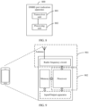
- the DMRS port indication apparatus includes a processor coupled to a memory.
- the processor is configured to support the apparatus in performing a corresponding function in the DMRS port indication method.
- the memory is configured to be coupled to the processor, and stores a computer program (or computer-executable instructions) and/or data necessary for the apparatus.
- the DMRS port indication apparatus may further include a communication interface, configured to support communication between the apparatus and another network element, for example, data and/or signal sending or receiving.
- the communication interface may be a transceiver, a circuit, a bus, a module, or another type of communication interface.
- the memory may be located inside the DMRS port indication apparatus and integrated with the processor, or may be located outside the DMRS port indication apparatus.
- the DMRS port indication apparatus includes a processor and a transceiver apparatus.
- the processor is coupled to the transceiver apparatus.
- the processor is configured to execute a computer program or instructions, to control the transceiver apparatus to receive and send information.
- the processor executes the computer program or the instructions, the processor is further configured to implement the foregoing method by using a logic circuit or executing code instructions.
- the transceiver apparatus may be a transceiver, a transceiver circuit, an interface circuit, or an input/output interface, and is configured to receive a signal from a DMRS port indication apparatus other than the DMRS port indication apparatus and transmit the signal to the processor or send a signal from the processor to a DMRS port indication apparatus other than the DMRS port indication apparatus.
- the transceiver apparatus is the transceiver circuit or the input/output interface.
- a sending unit may be an output unit, for example, an output circuit or a communication interface; and a receiving unit may be an input unit, for example, an input circuit or a communication interface.
- a sending unit may be a transmitter or a transmitter machine; and a receiving unit may be a receiver or a receiver machine.
- the quantity of candidate antenna ports corresponding to each candidate value is N.
- the first relationship further includes a quantity of DMRS code division multiplexing groups to which data is not mapped and that correspond to each of the at least one candidate value of the antenna port field in the DCI.
- DMRSs corresponding to candidate antenna ports corresponding to the at least one candidate value are mapped to one symbol, and the candidate antenna ports corresponding to the at least one candidate value belong to two DMRS code division multiplexing groups; or DMRSs corresponding to candidate antenna ports corresponding to the at least one candidate value are mapped to two symbols, and the candidate antenna ports corresponding to the at least one candidate value belong to one DMRS code division multiplexing group.
- DMRSs corresponding to candidate antenna ports corresponding to the at least one candidate value are mapped to one symbol, and the candidate antenna ports corresponding to the at least one candidate value belong to two DMRS code division multiplexing groups to which data is not mapped; or DMRSs corresponding to candidate antenna ports corresponding to the at least one candidate value are mapped to two symbols, and the candidate antenna ports corresponding to the at least one candidate value belong to one DMRS code division multiplexing group to which data is not mapped.
- the DMRSs corresponding to the candidate antenna ports corresponding to the at least one candidate value are mapped to one symbol, to reduce symbol overheads; or the candidate antenna ports corresponding to the at least one candidate value belong to one DMRS code division multiplexing group to which data is not mapped, and time-frequency resources corresponding to remaining code division multiplexing groups may be used to map data, to reduce a resource requirement and improve resource usage.
- the DMRSs are mapped to one symbol, and the candidate antenna ports corresponding to the at least one candidate value belong to two DMRS code division multiplexing groups; or the DMRSs are mapped to two symbols, and the candidate antenna ports corresponding to the at least one candidate value belong to one DMRS code division multiplexing group.
- the dmrs-Type is 1, the maxLength is 1, and N is 5; and a value of the antenna port field is a first value, the quantity of DMRS code division multiplexing groups to which data is not mapped is 2, and the antenna ports are 0 to 4.
- the dmrs-Type is 1, the maxLength is 1, and N is 6; and a value of the antenna port field is a second value, the quantity of DMRS code division multiplexing groups to which data is not mapped is 2, and the antenna ports are 0, 1, 2, 3, 4, and 6.
- the dmrs-Type is 1, the maxLength is 1, and N is 7; and a value of the antenna port field is a third value, the quantity of DMRS code division multiplexing groups to which data is not mapped is 2, and the antenna ports are 0 to 6.
- the dmrs-Type is 1, the maxLength is 1, and N is 8; and a value of the antenna port field is a fourth value, the quantity of DMRS code division multiplexing groups to which data is not mapped is 2, and the antenna ports are 0 to 7.
- the dmrs-Type is 1, the maxLength is 1, and N is 5; and the value of the antenna port field is the first value, the quantity of DMRS code division multiplexing groups to which data is not mapped is 2, and the antenna ports are 0, 1, 2, 3, and 8.
- the dmrs-Type is 1, the maxLength is 1, and N is 6; and the value of the antenna port field is the second value, the quantity of DMRS code division multiplexing groups to which data is not mapped is 2, and the antenna ports are 0, 1, 2, 3, 8, and 10.
- the dmrs-Type is 1, the maxLength is 1, and N is 7; and the value of the antenna port field is the third value, the quantity of DMRS code division multiplexing groups to which data is not mapped is 2, and the antenna ports are 0, 1, 2, 3, 8, 9, and 10.
- the dmrs-Type is 1, the maxLength is 1, and N is 8; and the value of the antenna port field is the fourth value, the quantity of DMRS code division multiplexing groups to which data is not mapped is 2, and the antenna ports are 0, 1, 2, 3, 8, 9, 10, and 11.
- the first antenna port group and the second antenna port group each include four antenna ports, and the first antenna port group and the second antenna port group each correspond to two CDM groups.
- the first antenna port group and the second antenna port group include a total of eight antenna ports, which respectively correspond to antenna port indexes 0, 1, 2, 3, 4, 5, 6, and 7, or respectively correspond to antenna port indexes 0, 1, 2, 3, 8, 9, 10, and 11.
- the two CDM groups corresponding to each of the first antenna port group and the second antenna port group are a CDM group 0 and a CDM group 1.
- the dmrs-Type is 1, the maxLength is 2, and N is 5; and a value of the antenna port field is a fifth value, the quantity of DMRS code division multiplexing groups to which data is not mapped is 1, the antenna ports are 0, 1, 4, 5, and 8, and the DMRSs are mapped to two symbols; and/or the value of the antenna port field is a sixth value, the quantity of DMRS code division multiplexing groups to which data is not mapped is 2, the antenna ports are 0 to 4, and the DMRSs are mapped to one symbol.
- the dmrs-Type is 1, the maxLength is 2, and N is 6; and a value of the antenna port field is a seventh value, the quantity of DMRS code division multiplexing groups to which data is not mapped is 1, the antenna ports are 0, 1, 4, 5, 8, and 9, and the DMRSs are mapped to two symbols; and/or the value of the antenna port field is an eighth value, the quantity of DMRS code division multiplexing groups to which data is not mapped is 2, the antenna ports are 0, 1, 2, 3, 4, and 6, and the DMRSs are mapped to one symbol.
- the dmrs-Type is 1, the maxLength is 2, and N is 7; and a value of the antenna port field is a ninth value, the quantity of DMRS code division multiplexing groups to which data is not mapped is 1, the antenna ports are 0, 1, 4, 5, 8, 9, and 12, and the DMRSs are mapped to two symbols; and/or the value of the antenna port field is a tenth value, the quantity of DMRS code division multiplexing groups to which data is not mapped is 2, the antenna ports are 0 to 6, and the DMRSs are mapped to one symbol.
- the dmrs-Type is 1, the maxLength is 2, and N is 8; and a value of the antenna port field is an eleventh value, the quantity of DMRS code division multiplexing groups to which data is not mapped is 1, the antenna ports are 0, 1, 4, 5, 8, 9, 12, and 13, and the DMRSs are mapped to two symbols; and/or the value of the antenna port field is a twelfth value, the quantity of DMRS code division multiplexing groups to which data is not mapped is 2, the antenna ports are 0 to 7, and the DMRSs are mapped to one symbol.
- the first antenna port group and the second antenna port group each include eight antenna ports, and the first antenna port group and the second antenna port group each correspond to two CDM groups.
- the first antenna port group and the second antenna port group include a total of 16 antenna ports, which respectively correspond to antenna port indexes 0, 1, 2, 3, 4, 5, 6, 7, 8, 9, 10, 11, 12, 13, 14, and 15.
- the two CDM groups corresponding to each of the first antenna port group and the second antenna port group are a CDM group 0 and a CDM group 1.
- the dmrs-Type is 2, the maxLength is 1, and N is 5; and a value of the antenna port field is a thirteenth value, the quantity of DMRS code division multiplexing groups to which data is not mapped is 3, and the antenna ports are 0 to 4; and/or the value of the antenna port field is a fourteenth value, the quantity of DMRS code division multiplexing groups to which data is not mapped is 2, and the antenna ports are 0, 1, 2, 3, and 6.
- the dmrs-Type is 2, the maxLength is 1, and N is 6; and a value of the antenna port field is a fifteenth value, the quantity of DMRS code division multiplexing groups to which data is not mapped is 3, and the antenna ports are 0 to 5; and/or the value of the antenna port field is a sixteenth value, the quantity of DMRS code division multiplexing groups to which data is not mapped is 2, and the antenna ports are 0, 1, 2, 3, 6, and 8.
- the dmrs-Type is 2, the maxLength is 1, and N is 7; and a value of the antenna port field is a seventeenth value, the quantity of DMRS code division multiplexing groups to which data is not mapped is 3, and the antenna ports are 0 to 6; and/or the value of the antenna port field is an eighteenth value, the quantity of DMRS code division multiplexing groups to which data is not mapped is 2, and the antenna ports are 0, 1, 2, 3, 6, 7, and 8.
- the dmrs-Type is 2, the maxLength is 1, and N is 8; and a value of the antenna port field is a nineteenth value, the quantity of DMRS code division multiplexing groups to which data is not mapped is 3, and the antenna ports are 0, 1, 2, 3, 4, 5, 6, and 8; and/or the value of the antenna port field is a twentieth value, the quantity of DMRS code division multiplexing groups to which data is not mapped is 2, and the antenna ports are 0, 1, 2, 3, 6, 7, 8, and 9.
- the dmrs-Type is 2, the maxLength is 1, and N is 6; and the value of the antenna port field is the fifteenth value, the quantity of DMRS code division multiplexing groups to which data is not mapped is 3, and the antenna ports are 0 to 5; and/or the value of the antenna port field is the sixteenth value, the quantity of DMRS code division multiplexing groups to which data is not mapped is 2, and the antenna ports are 0, 1, 2, 3, 12, and 14.
- the dmrs-Type is 2, the maxLength is 1, and N is 7; and the value of the antenna port field is the seventeenth value, the quantity of DMRS code division multiplexing groups to which data is not mapped is 3, and the antenna ports are 0, 1, 2, 3, 4, 5, and 12; and/or the value of the antenna port field is the eighteenth value, the quantity of DMRS code division multiplexing groups to which data is not mapped is 2, and the antenna ports are 0, 1, 2, 3, 12, 13, and 14.
- the first antenna port group and the second antenna port group each include six antenna ports, and the first antenna port group and the second antenna port group each correspond to three CDM groups.
- the first antenna port group and the second antenna port group include a total of 12 antenna ports, which respectively correspond to antenna port indexes 0, 1, 2, 3, 4, 5, 6, 7, 8, 9, 10, and 11, or respectively correspond to antenna port indexes 0, 1, 2, 3, 4, 5, 12, 13, 14, 15, 16, and 17.
- the three CDM groups corresponding to each of the first antenna port group and the second antenna port group are a CDM group 0, a CDM group 1, and a CDM group 2.
- the dmrs-Type is 2, the maxLength is 2, and N is 5; and a value of the antenna port field is a twenty-first value, the quantity of DMRS code division multiplexing groups to which data is not mapped is 3, the antenna ports are 0 to 4, and the DMRSs are mapped to one symbol; and/or the value of the antenna port field is a twenty-second value, the quantity of DMRS code division multiplexing groups to which data is not mapped is 2, the antenna ports are 0, 1, 2, 3, and 6, and the DMRSs are mapped to one symbol; and/or the value of the antenna port field is a twenty-third value, the quantity of DMRS code division multiplexing groups to which data is not mapped is 1, the antenna ports are 0, 1, 6, 7, and 12, and the DMRSs are mapped to two symbols.
- the dmrs-Type is 2, the maxLength is 2, and N is 6; and a value of the antenna port field is a twenty-fourth value, the quantity of DMRS code division multiplexing groups to which data is not mapped is 3, the antenna ports are 0 to 5, and the DMRSs are mapped to one symbol; and/or the value of the antenna port field is a twenty-fifth value, the quantity of DMRS code division multiplexing groups to which data is not mapped is 2, the antenna ports are 0, 1, 2, 3, 6, and 8, and the DMRSs are mapped to one symbol; and/or the value of the antenna port field is a twenty-sixth value, the quantity of DMRS code division multiplexing groups to which data is not mapped is 1, the antenna ports are 0, 1, 6, 7, 12, and 13, and the DMRSs are mapped to two symbols.
- the dmrs-Type is 2, the maxLength is 2, and N is 7; and a value of the antenna port field is a twenty-seventh value, the quantity of DMRS code division multiplexing groups to which data is not mapped is 2, the antenna ports are 0, 1, 2, 3, 6, 7, and 8, and the DMRSs are mapped to one symbol; and/or the value of the antenna port field is a twenty-eighth value, the quantity of DMRS code division multiplexing groups to which data is not mapped is 1, the antenna ports are 0, 1, 6, 7, 12, 13, and 18, and the DMRSs are mapped to two symbols.
- the dmrs-Type is 2, the maxLength is 2, and N is 8; and a value of the antenna port field is a twenty-ninth value, the quantity of DMRS code division multiplexing groups to which data is not mapped is 2, the antenna ports are 0, 1, 2, 3, 6, 7, and 8, and the DMRSs are mapped to one symbol; and/or a value of the antenna port field is a thirtieth value, the quantity of DMRS code division multiplexing groups to which data is not mapped is 1, the antenna ports are 0, 1, 6, 7, 12, 13, 18, and 19, and the DMRSs are mapped to two symbols.
- the first antenna port group and the second antenna port group each include 12 antenna ports, and the first antenna port group and the second antenna port group each correspond to three CDM groups.
- the first antenna port group and the second antenna port group include a total of 24 antenna ports, which respectively correspond to antenna port indexes 0, 1, 2, 3, 4, 5, 6, 7, 8, 9, 10, 11, 12, 13, 14, 15, 16, 17, 18, 19, 20, 21, 22, and 23.
- the three CDM groups corresponding to each of the first antenna port group and the second antenna port group are a CDM group 0, a CDM group 1, and a CDM group 2.
- the dmrs-Type is 1, the maxLength is 2, N is 5, a value of the antenna port field is a thirty-first value, the quantity of code division multiplexing groups is 2, the antenna ports are 0 to 4, and the DMRSs are mapped to two symbols; and/or the dmrs-Type is 1, the maxLength is 2, N is 6, the value of the antenna port field is a thirty-second value, the quantity of code division multiplexing groups is 2, the antenna ports are 0, 1, 2, 3, 4, and 6, and the DMRSs are mapped to two symbols; and/or the dmrs-Type is 1, the maxLength is 2, N is 7, the value of the antenna port field is a thirty-third value, the quantity of code division multiplexing groups is 2, the antenna ports are 0 to 6, and the DMRSs are mapped to two symbols; and/or the dmrs-Type is 1, the maxLength is 2, N is 8, the value of the
- a communication system includes the DMRS port indication apparatus according to the third aspect and the DMRS port indication apparatus according to the fourth aspect.
- a computer-readable storage medium stores a computer program or instructions.
- the program or the instructions are executed by a processor, the method according to any one of the first aspect, the second aspect, or the implementations of the first aspect or the second aspect is performed.
- a circuit is provided.
- the circuit is coupled to a memory, and the circuit is configured to perform the method according to any one of the first aspect, the second aspect, or the implementations of the first aspect or the second aspect.
- the circuit may include a chip circuit.
- the technical solutions provided in this application may be applied to various communication systems, for example, a long term evolution (long term evolution, LTE) system, a 5th generation (5th generation, 5G) communication system (or referred to as a new radio (new radio, NR) system), and another future communication system such as a 6th generation (6th generation, 6G) communication system.
- LTE long term evolution
- 5th generation, 5G 5th generation
- NR new radio
- 6th generation 6th generation
- the technical solutions provided in this application may be further applied to an internet of things (internet of things, IoT) system, a narrowband internet of things (narrowband internet of things, NB-IoT) system, and the like.
- IoT internet of things
- NB-IoT narrowband internet of things
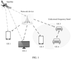
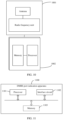
- FIG. 1 is a diagram of a communication system according to this application.
- the communication system includes at least one network device and at least one terminal.
- one network device and a plurality of terminals (user equipment (user equipment, UE) 1 to UE 5 in the figure) form the communication system.
- all the UE 1 to the UE 5 may communicate with the network device.
- a link environment of the communication system includes uplink, downlink, and side-line (side-link) transmission.
- Information transmitted on a link includes actually transmitted data information and control information for indicating or scheduling actual data.
- the UE 3, the UE 4, and the UE 5 may also form a communication system, and a link transmission environment of the communication system is consistent with that described above. Specific information exchange depends on a network configuration manner.
- the network device may be a device that can communicate with the terminal.
- the network device may be any device having a wireless transceiver function.
- the network device includes but is not limited to: a base station such as a NodeB (NodeB), an evolved base station such as an evolved NodeB (eNodeB), a base station in a 5th generation (5th generation, 5G) communication system, a base station or a network device in a future communication system, and an access node, a wireless relay node, a wireless backhaul node in a Wi-Fi system, and the like.
- the network device may alternatively be a radio controller in a cloud radio access network (cloud radio access network, CRAN) scenario.
- the network device may alternatively be a small cell, a transmission node (transmission reference point, TRP), or the like.
- a specific technology and a specific device form used by the network device are not limited in embodiments of this application.
- the network device may alternatively be an access node, a wireless relay node, a wireless backhaul node, or the like in a wireless local area network (wireless fidelity, Wi-Fi) system.
- the network device may alternatively be a radio controller in a cloud radio access network (cloud radio access network, CRAN) scenario.
- the base station may include a central unit (central unit, CU), a distributed unit (distributed unit, DU), and the like.
- the CU may be further divided into a CU-control plane (control plane, CP), a CU-user plane (user plane, UP), and the like.
- the base station may alternatively be an open radio access network (open radio access network, ORAN) architecture or the like.
- ORAN open radio access network
- the terminal is a device having a wireless transceiver function.
- the terminal may be deployed on land, and includes an indoor device, an outdoor device, a handheld device, a wearable device, or a vehicle-mounted device.
- the terminal may alternatively be deployed on water, for example, on a ship.
- the terminal may alternatively be deployed in air, for example, deployed on an airplane, a balloon, or a satellite.
- the terminal device may be a mobile phone (mobile phone), a tablet computer (pad), a computer having a wireless transceiver function, a virtual reality (virtual reality, VR) terminal device, an augmented reality (augmented reality, AR) terminal device, a wireless terminal in industrial control (industrial control), a wireless terminal in self-driving (self-driving), a wireless terminal in remote medical (remote medical), a wireless terminal in a smart grid (smart grid), a wireless terminal in transportation safety (transportation safety), a wireless terminal in a smart city (smart city), a wireless terminal in a smart home (smart home), or the like.
- An application scenario is not limited in embodiments of this application.
- the terminal device sometimes may also be referred to as user equipment, an access terminal device, a UE unit, a mobile station, a remote station, a remote terminal device, a mobile device, a terminal (terminal), a wireless communication device, a UE agent, a UE apparatus, or the like.
- the terminals may further communicate with each other by using a technology such as device to device (device to device, D2D), vehicle-to-everything (vehicle-to-everything, V2X), or machine to machine (machine to machine, M2M).
- a technology such as device to device (device to device, D2D), vehicle-to-everything (vehicle-to-everything, V2X), or machine to machine (machine to machine, M2M).
- D2D device to device
- V2X vehicle-to-everything
- M2M machine to machine
- system and “network” may be used interchangeably in embodiments of this application.
- network may be used interchangeably in embodiments of this application.
- the following describes concepts related to embodiments of this application.
- the DMRS is used to estimate an equivalent channel matrix undergone by a data channel (for example, a physical uplink shared channel (physical uplink shared channel, PUSCH) or a physical downlink shared channel (physical downlink shared channel, PDSCH)) or a control channel (for example, a physical uplink control channel (physical uplink control channel, PUCCH) or a physical downlink control channel (physical downlink control channel, PDCCH)), and therefore is used for data detection and demodulation.
- PUSCH is used as an example.
- the DMRS and a sent data signal are usually precoded in a same manner, to ensure that the DMRS and data undergo a same equivalent channel.
- a vector of a DMRS sent by a transmit end is s
- a vector of a sent data symbol is x
- a same precoding operation is performed on the DMRS and the data (multiplied by a same precoding matrix P)
- vectors of corresponding received signals of a receive end may be represented as:
- equivalent channels that both a data signal and a reference signal undergo are H ⁇ .
- the receive end may obtain estimation of the equivalent channel H ⁇ based on the known vector s of the DMRS by using a channel estimation algorithm (for example, least squares (least squares, LS) channel estimation or minimum mean square error (minimum mean square error, MMSE) channel estimation).
- a channel estimation algorithm for example, least squares (least squares, LS) channel estimation or minimum mean square error (minimum mean square error, MMSE) channel estimation.
- LS least squares
- minimum mean square error minimum mean square error
- the DMRS is used to estimate the equivalent channel H ⁇ , and a dimension of the equivalent channel is N R ⁇ R.
- N R is a quantity of receiving antennas
- R is a quantity of transport streams (also referred to as a quantity of transport layers, a quantity of spatial layers, or a rank (rank)).
- one DMRS port corresponds to one spatial layer.
- One DMRS port corresponds to one group of DMRS symbols or one group of DMRS sequences.
- the DMRS symbol includes a plurality of DMRS symbol elements, which are correspondingly mapped to corresponding time-frequency resources for transmission.
- a quantity of corresponding DMRS ports is R .
- different DMRS ports are usually orthogonal ports.
- DMRS symbols corresponding to the different DMRS ports are orthogonal in at least one of frequency domain, time-frequency domain, or code domain.
- an antenna port and the DMRS port represent a same meaning, and may be used interchangeably.
- DMRS resources corresponding to a plurality of DMRS ports are usually mapped to preset time-frequency resources in a frequency division multiplexing (frequency division multiplexing, FDM), time division multiplexing (time division multiplexing, TDM), or code division multiplexing (code division multiplexing, CDM) manner.
- FDM frequency division multiplexing
- TDM time division multiplexing
- CDM code division multiplexing
- 5G NR supports two DMRS resource mapping types.
- a type 1 (Type 1) DMRS may support a maximum of eight orthogonal ports.
- a type 2 (Type 2) DMRS may support a maximum of 12 orthogonal ports.
- a plurality of DMRS symbols need to be sent on a plurality of time-frequency resources.
- the DMRS may occupy at least one orthogonal frequency division multiplexing (orthogonal frequency division multiplexing, OFDM) symbol in time domain, and bandwidth occupied in frequency domain is the same as scheduled bandwidth of a scheduled data signal.
- a plurality of DMRS symbols corresponding to one port correspond to one reference signal sequence, and the reference signal sequence includes a plurality of reference signal sequence elements.
- a DMRS reference signal sequence may be a gold sequence.
- the DMRS reference signal sequence is the gold sequence.
- a pseudo-random sequence c ( n ) may be a gold sequence whose sequence length is 31.
- N C 1600.
- l represents an index of an OFDM symbol included in one slot
- n s , f ⁇ represents an index of a slot in one system frame
- N ID 0 , N ID 1 ⁇ ⁇ 0,1, ... ,65535 ⁇ may be configured by using higher layer signaling.
- ⁇ represents an index of a code division multiplexing group corresponding to the DMRS port.
- a DMRS reference signal sequence corresponding to a port is multiplied by a corresponding cover code sequence and then mapped to a corresponding time-frequency resource.
- two types of DMRS configuration manners are defined, including a Type 1 DMRS and a Type 2 DMRS.
- an m th reference sequence element r ( m ) in a corresponding reference signal sequence is mapped, according to the following rule, to a resource element (resource element, RE) whose index is ( k , l ) p, ⁇ .
- RE resource element
- the RE whose index is ( k,l ) p, ⁇ corresponds to an OFDM symbol whose index is l in one slot in time domain, and corresponds to a subcarrier whose index is k in frequency domain.
- the mapping rule satisfies: a k .
- ⁇ is a subcarrier spacing parameter
- a k . l p ⁇ is a DMRS signal symbol that corresponds to the port p and that is mapped to the RE whose index is ( k,l ) p, ⁇
- l is a symbol index of a start OFDM symbol occupied by the DMRS signal symbol or a symbol index of a reference OFDM symbol.
- ⁇ PDSCH DMRS is a power scaling factor
- w t ( l' ) is a time domain cover code element corresponding to an OFDM symbol whose index is l'
- w f ( k' ) is a frequency domain cover code element corresponding to a subcarrier whose index is k'
- m 2 n + k '
- ⁇ is a subcarrier offset factor
- Type 1 DMRS configuration type 1 mapping rule
- values of w f ( k '), w t ( l' ), and ⁇ that correspond to the DMRS port p may be determined according to Table 1.
- the type 1 DMRS may support a maximum of eight orthogonal ports (1000 to 1007), p represents a DMRS port number, ⁇ represents the index of the code division multiplexing group corresponding to the DMRS port, ⁇ is the subcarrier offset factor, w t ( l' ) is the time domain cover code element corresponding to the OFDM symbol whose index is l', and w f ( k' ) is the frequency domain cover code element corresponding to the subcarrier whose index is k'.
- Type 2 DMRS configuration type 2 mapping rule
- values of w f ( k' ), w t ( l' ) , and ⁇ that correspond to the DMRS port p may be determined according to Table 2.
- the type 2 DMRS may support a maximum of 12 orthogonal ports (1000 to 1011), ⁇ is the index of the code division multiplexing group to which the port p belongs, and DMRS ports in a same code division multiplexing group occupy a same time-frequency resource.
- time-frequency resource mapping manners of a single-symbol Type 1 DMRS and a double-symbol Type 1 DMRS are shown in a first picture and a second picture from the left of FIG. 2 .
- the four DMRS ports are divided into two code division multiplexing groups (CDM groups).
- a CDM group 0 includes a port 0 and a port 1
- a CDM group 1 includes a port 2 and a port 3.
- Frequency division multiplexing is performed between the CDM group 0 and the CDM group 1 (mapped to different frequency domain resources).
- DMRS ports included in the CDM group are mapped to a same time-frequency resource.
- Reference signals corresponding to the DMRS ports included in the CDM group are distinguished by using orthogonal cover codes (orthogonal cover codes, OCCs), to ensure orthogonality of the DMRS ports in the CDM group, and further suppress interference between DMRSs that are transmitted on different antenna ports.
- the port 0 and the port 1 are in a same RE, and resource mapping is performed in a comb manner in frequency domain. In other words, adjacent frequency domain resources occupied by the port 0 and the port 1 are separated by one subcarrier. For one DMRS port, two adjacent occupied REs correspond to one OCC codeword sequence whose length is 2.
- a group of OCC codeword sequences (+1+1 and +1-1) whose lengths are 2 are used for the port 0 and the port 1.
- the port 2 and the port 3 are in a same RE, and are mapped, in a comb manner in frequency domain, to REs that are not occupied by the port 0 and the port 1.
- a group of OCC codeword sequences (+1+1 and +1-1) whose lengths are 2 are used for the port 2 and the port 3.
- a double-symbol DMRS supports a maximum of eight ports.
- the eight DMRS ports are divided into two code division multiplexing groups.
- a CDM group 0 includes a port 0, a port 1, a port 4, and a port 5, and a CDM group 1 includes a port 2, a port 3, a port 6, and a port 7.
- Frequency division multiplexing is performed between the CDM group 0 and the CDM group 1.
- Reference signals corresponding to DMRS ports included in the CDM group are distinguished by using OCCs. Specifically, the port 0, the port 1, the port 4, and the port 5 are in a same RE, and resource mapping is performed in a comb manner in frequency domain.
- adjacent frequency domain resources occupied by the port 0, the port 1, the port 4, and the port 5 are separated by one subcarrier.
- two adjacent occupied subcarriers and two OFDM symbols correspond to one OCC codeword sequence whose length is 4.
- a group of OCC codes (+1+1+1+1/+1+1-1-1/+1-1+1-1/+1-1-1+1) whose lengths are 4 are used for the port 0, the port 1, the port 4, and the port 5.
- the port 2, the port 3, the port 6, and the port 7 are in a same RE, and are mapped, in a comb manner in frequency domain, to subcarriers that are not occupied by the port 0, the port 1, the port 4, and the port 5.
- a group of OCC codes (+1+1+1+1/+1+1-1-1/+1-1+1-1/+1-1-1+1) whose lengths are 4 are used for the port 2, the port 3, the port 6, and the port 7.
- time-frequency resource mapping manners of a single-symbol DMRS and a double-symbol DMRS are shown in a third picture and a fourth picture from the left of FIG. 2 .
- a single-symbol Type 2 DMRS supports a maximum of six ports.
- the six DMRS ports are divided into three code division multiplexing groups, frequency division multiplexing is performed between CDM groups, and orthogonality of reference signals corresponding to DMRS ports included in the CDM is ensured by using OCCs.
- a CDM group 0 includes a port 0, a port 1, a CDM group 1 includes a port 2 and a port 3, and a CDM group 2 includes a port 4 and a port 5.
- Frequency division multiplexing is performed between the CDM groups (mapped to different frequency domain resources).
- the reference signals corresponding to the DMRS ports included in the CDM group are mapped to a same time-frequency resource.
- the reference signals corresponding to the DMRS ports included in the CDM group are distinguished by using the OCCs.
- a DMRS reference signal corresponding to the DMRS port is mapped, in frequency domain, to a plurality of resource sub-blocks including two contiguous subcarriers, and adjacent resource sub-blocks are separated by four subcarriers in frequency domain.
- the port 0 and the port 1 are in a same RE, and resource mapping is performed in a comb manner.
- a frequency domain resource granularity is one RB.
- the port 0 and the port 1 occupy a subcarrier 0, a subcarrier 1, a subcarrier 6, and a subcarrier 7.
- the port 2 and the port 3 occupy a subcarrier 2, a subcarrier 3, a subcarrier 8, and a subcarrier 9.
- the port 4 and the port 5 occupy a subcarrier 4, a subcarrier 5, a subcarrier 10, and a subcarrier 11.
- Two DMRS ports included in one CDM group correspond, in two adjacent subcarriers, to OCC codeword sequences (+1+1 and +1-1) whose lengths are 2.
- a double-symbol Type 2 DMRS supports a maximum of 12 ports.
- the 12 DMRS ports are divided into three CDM groups, frequency division multiplexing is performed between CDM groups, and orthogonality of reference signals corresponding to DMRS ports included in the CDM is ensured by using OCCs.
- a CDM group 0 includes a port 0, a port 1, a port 6, and a port 7, a CDM group 1 includes a port 2, a port 3, a port 8, and a port 9, and a CDM group 2 includes a port 4, a port 5, a port 10, and a port 11. Frequency division multiplexing is performed between the CDM groups (mapped to different frequency domain resources).
- the reference signals corresponding to the DMRS ports included in the CDM group are mapped to a same time-frequency resource.
- the reference signals corresponding to the DMRS ports included in the CDM group are distinguished by using the OCCs.
- a DMRS reference signal corresponding to the DMRS port is mapped, in frequency domain, to a plurality of resource sub-blocks including two contiguous subcarriers, and adjacent resource sub-blocks are separated by four subcarriers in frequency domain.
- ports included in one CDM group are in a same RE, and resource mapping is performed in a comb manner in frequency domain.
- a frequency domain resource granularity is one RB.
- the port 0, the port 1, the port 6, and the port 7 occupy a subcarrier 0, a subcarrier 1, a subcarrier 6, and a subcarrier 7 that correspond to an OFDM symbol 1 and an OFDM symbol 2.
- the port 2, the port 3, the port 8, and the port 9 occupy a subcarrier 2, a subcarrier 3, a subcarrier 8, and a subcarrier 9 that correspond to the OFDM symbol 1 and the OFDM symbol 2.
- the port 4, the port 5, the port 10, and the port 11 occupy a subcarrier 4, a subcarrier 5, a subcarrier 10, and a subcarrier 11 that correspond to the OFDM symbol 1 and the OFDM symbol 2.
- Four DMRS ports included in one CDM group correspond, in two adjacent subcarriers corresponding to two OFDM symbols, to OCC codeword sequences (+1+1+1+1/+1+1-1-1/+1-1+1-1/+1-1-1+1) whose lengths are 4.
- a quantity of terminals further increases. This imposes a higher requirement on a quantity of MIMO transport streams.
- a quantity of transmission/receiving antennas further increases (a quantity of transmission antennas of a network device supports 128 transmission antennas (transmission antennas, T) or 256T, and a quantity of receiving antennas of a terminal supports 8 receiving antennas (receiving antennas, R)), and channel information is obtained more accurately, so that a larger quantity of transport streams can be further supported to improve spectral efficiency of the MIMO system.
- a simplest method for expanding an existing quantity of orthogonal DMRS ports is to increase a time-frequency resource occupied by a DMRS. This method can ensure that a quantity of DMRS symbols corresponding to each DMRS port remains unchanged.
- multiplication of DMRS overheads also reduces spectral efficiency of the system by multiple times.
- DMRS resources corresponding to more orthogonal DMRS ports are multiplexed while a same time-frequency resource (overhead) is ensured.
- overhead time-frequency resource
- an orthogonal DMRS port or a DMRS port with low cross-correlation may be expanded in code domain by using a proper DMRS sequence design.
- a double-symbol Type 1 DMRS is used as an example.
- a DMRS port expansion method is shown in FIG. 3 .
- An existing DMRS port group includes eight Type 1 DMRS ports defined in the existing NR protocol, and an expanded port group includes eight newly added DMRS ports. Therefore, a maximum of 16 DMRS ports may be supported in total.
- one CDM group corresponds to four DMRS ports. Code division multiplexing is performed on the four DMRS ports in the CDM group by using OCC codes ( w 1 , w 2 , w 3 , w 4 ) whose lengths are 4, and the four DMRS ports are mapped to two subcarriers and two OFDM symbols. Values of w 1 , w 2 , w 3 , w 4 are shown in Table 1.
- the newly added DMRS port group also corresponds to two CDM groups, and each CDM group corresponds to four DMRS ports.
- One CDM group corresponds to four DMRS ports, and the four DMRS ports occupy a same time-frequency resource as DMRS ports that belong to a same CDM group and that are defined in the existing NR protocol.
- a CDM group 0 is used as an example.
- DMRS ports 8, 9, 12, and 13 are newly added, and occupy subcarriers whose indexes are 0, 2, 4, 6, 8, and 10 in one RB.
- the newly added DMRS ports correspond to two layers of cover codes, and a time-frequency resource mapping manner of the DMRS port may be represented as follows: a k .
- ⁇ PDSCH DMRS and r (2 n + k' ) are the same as those in the formula (1).
- c ( k',l' ) represents an inner cover code, may be an OCC code (for example, a walsh code) whose length is 4, and is used to ensure orthogonality of four newly added DMRS ports multiplexed in one CDM group.
- DMRS port expansion design For a double-symbol Type 2 DMRS, a similar DMRS port expansion design may be used.
- a DMRS port expansion method is shown in FIG. 4 .
- a time-frequency resource mapping manner of a Type 2 DMRS expanded port is also shown in the formula (2).
- a similar DMRS port expansion design may also be used.
- a maximum quantity of supported orthogonal DMRS ports is 4.
- the maximum quantity of supported orthogonal DMRS ports may be increased to 8.
- a maximum quantity of supported orthogonal DMRS ports is 6.
- the maximum quantity of supported orthogonal DMRS ports may be increased to 12.
- a sending behavior of the terminal is scheduled by the network device.
- the network device needs to notify, via indication information, the terminal of a quantity of data streams (also referred to as a rank) corresponding to to-be-sent uplink data and a corresponding DMRS port index. Therefore, the terminal may send the uplink data and the DMRS on a corresponding time-frequency resource at a sending moment of the uplink data based on the indicated DMRS and the indicated quantity of transport streams.
- the NR protocol is used as an example. Currently, transmission of a maximum of four streams is supported in an uplink (uplink, UL).
- a single-symbol Type 1 DMRS is used as an example.
- DMRS port index tables corresponding to a rank 1 to a rank 4 are shown in Table 7 to Table 10.
- a double-symbol Type 1 DMRS is used as an example.
- DMRS port index tables corresponding to the rank 1 to the rank 4 are shown in Table 11 to Table 14.
- the terminal may select a corresponding DMRS port index table based on an indicated rank value, to determine an indicated port index.
- DMRS port indexes 1000+DMRS port
- Quantity of front-loaded symbols 0 2 0 to 3 1 1 2 0, 1, 4, and 5 2 2 2 2, 3, 6, and 7 2 3 2 0, 2, 4, and 6 2 4 to 15 Reserved Reserved Reserved
- the network device may also indicate, to the terminal, a quantity of to-be-sent data streams, that is, a rank, and a corresponding DMRS port index.
- DCI signaling includes an antenna port field, indicating an allocated DMRS port index.
- the antenna port field in the DCI signaling indicates an index value in a DMRS port table corresponding to a value of the dmrs-Type and a value of the maxLength that are configured by using higher layer signaling, and each index value corresponds to one or more DMRS port indexes.
- the NR system can simultaneously process a maximum of two codewords (codewords): a codeword 0 and a codeword 1.
- codewords codewords
- a single-codeword stream may be mapped to a maximum of four layers (namely, four DMRS ports).
- a double-codeword stream may be mapped to a maximum of eight layers. In this scenario, only the single-codeword stream is needed. For example, the codeword 0 is enabled (enabled), and the codeword 1 is disabled (disabled).
- DMRS port indexes 1000+DMRS port
- One codeword A codeword 0 is enabled, and a codeword 1 is disabled Value Quantity of DMRS code division multiplexing groups to which data is not mapped DMRS port 0 1 0 1 1 1 2 1 0 and 1 3 2 0 4 2 1 5 2 2 6 2 3 7 2 0 and 1 8 2 2 and 3 9 2 0 to 2 10 2 0 to 3 11 2 0 and 2 12 to 15 Reserved Reserved
- the antenna port field includes four bits, and corresponds to 16 values of the antenna port field. Values 12 to 15 of the antenna port field are used as reserved bits.
- a single time domain symbol may support a maximum of four DMRS ports: a port 0 to a port 3.
- the four DMRS ports may be divided into two CDM groups: a CDM group 0 and a CDM group 1.
- the quantity of DMRS code division multiplexing groups to which data is not mapped decides whether the DMRS and a data signal may be multiplexed on a same OFDM symbol.
- the quantity of DMRS code division multiplexing groups to which data is not mapped is 1, it indicates that the data signal is not mapped to a time-frequency resource corresponding to one CDM group, and a time-frequency resource corresponding to one remaining CDM group may be used to map the data signal.
- the time-frequency resource to which the data signal is not mapped is a time-frequency resource corresponding to the CDM group 0, and the time-frequency resource to which the data may be mapped is a time-frequency resource corresponding to the CDM group 1.
- the quantity of DMRS code division multiplexing groups to which data is not mapped is 2, it indicates that the data signal is not mapped to time-frequency resources corresponding to the two CDM groups.
- the data symbol is not mapped to an OFDM symbol to which the DMRS is mapped.
- the time-frequency resource to which the data signal is not mapped may be used to send the DMRS, or may be idle and is not used to send a signal.
- the antenna port field is five bits, and may have 32 values.
- the single-codeword stream is needed.
- the codeword 0 is enabled, and the codeword 1 is disabled.
- the double-codeword stream is needed. For example, both the codeword 0 and the codeword 1 are enabled.
- a quantity of front-loaded symbols (Number of front-load symbols) is 1, that is, the DMRS is allowed to be mapped to one time domain symbol.
- the quantity of front-loaded symbols is 2, that is, the DMRS is allowed to be mapped to two time domain symbols.
- One codeword A codeword 0 is enabled, and a codeword 1 is disabled
- DMRS port Quantity of front-loaded symbols Value Quantity of DMRS code division multiplexing groups to which data is not mapped DMRS port Quantity of front-loaded symbols 0 1 0 1 0 3 0 to 4 1 1 1 1 1 1 3 0 to 5 1 2 1 0 and 1 1 2 2 0, 1, 2, 3, and 6 2 3 2 0 1 3 2 0, 1,2,3,6, and 8 2 4 2 1 1 4 2 0, 1, 2, 3, 6, 7, and 8 2 5 2 2 1 5 2 0, 1, 2, 3, 6, 7, 8, and 9 2 6 2 3
- the quantity of DMRS code division multiplexing groups to which data is not mapped decides whether the DMRS and a data signal may be multiplexed on a same OFDM symbol.
- the quantity of DMRS code division multiplexing groups to which data is not mapped is 1, it indicates that the data signal is not mapped to a time-frequency resource corresponding to one CDM group, and time-frequency resources corresponding to two remaining CDM groups may be used to map the data signal.
- the time-frequency resource to which the data signal is not mapped is a time-frequency resource corresponding to a CDM group 0, and the time-frequency resources to which the data may be mapped are a time-frequency resource corresponding to a CDM group 1 and a time-frequency resource corresponding to a CDM group 2.
- the quantity of DMRS code division multiplexing groups to which data is not mapped is 2, it indicates that the data signal is not mapped to time-frequency resources corresponding to two CDM groups, and a time-frequency resource corresponding to one remaining CDM group may be used to map the data signal.
- the time-frequency resources to which the data signal is not mapped are the time-frequency resources corresponding to the CDM group 0 and the CDM group 1, and the time-frequency resource to which the data may be mapped is the time-frequency resource corresponding to the CDM group 2.
- the quantity of DMRS code division multiplexing groups to which data is not mapped is 3, it indicates that the data signal is not mapped to time-frequency resources corresponding to the three CDM groups.
- the data symbol is not mapped to an OFDM symbol to which the DMRS is mapped.
- the time-frequency resource to which the data signal is not mapped may be used to send the DMRS, or may be idle and is not used to send a signal.
- one time domain symbol may support a maximum of six orthogonal DMRS ports.
- the antenna port field is six bits, and may have 64 values.
- a quantity of front-loaded symbols is 2, that is, the DMRS is allowed to be mapped to two time domain symbols.
- DMRS port indication of the downlink system it can be learned that currently, transmission of a maximum of eight streams may be supported in the downlink, but large DMRS overheads are needed to support a rank 5 to a rank 8.
- a Type 1 DMRS needs to use a double-symbol DMRS to support transmission of more than four streams.
- a single-symbol Type 2 DMRS only transmission of a maximum of the rank 6 can be supported.
- a double-symbol DMRS needs to be used. Compared with the single-symbol DMRS, the double-symbol DMRS increases additional overheads of one OFDM symbol.
- the DMRS may be expanded, to support twice the quantity of orthogonal DMRS ports. This provides a new design capability for an optional DMRS port index design of the rank 5 to the rank 8. However, currently, there is no solution of how to indicate DMRS ports of the rank 5 to the rank 8.
- this application provides a DMRS port indication solution.
- a dmrs-Type and a maxLength are obtained.
- a first relationship is determined, where the first relationship is associated with the dmrs-Type and the maxLength, the first relationship includes at least one candidate value of an antenna port field and candidate antenna ports corresponding to each of the at least one candidate value of the antenna port field, a quantity of candidate antenna ports corresponding to each candidate value is greater than or equal to N, N is greater than 4, and the candidate antenna ports corresponding to each candidate value are included in a first antenna port group and/or a second antenna port group.
- DCI is received, corresponding antenna ports are determined based on one value indicated by the antenna port field in the DCI, and DMRSs corresponding to the determined antenna ports are received, to implement an indication for DMRS antenna ports of more than four streams.
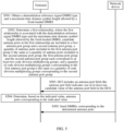
- FIG. 5 is a schematic flowchart of a DMRS port indication method according to an embodiment of this application.
- the method may include the following steps.
- S501 A terminal obtains a demodulation reference signal DMRS type (dmrs-Type) and a maximum quantity of DMRS symbols (maxLength).
- a network device may send first signaling, where the first signaling includes the dmrs-Type and the maxLength.
- the network device may include the dmrs-Type and the maxLength in higher layer signaling (higher layer parameter), for example, a radio resource control (radio resource control, RRC) or radio resource control reconfiguration (RRCReconfiguration) message.
- the dmrs-Type may be a Type 1 or a Type 2.
- an optional value of the dmrs-Type may further include a Type 1E and a Type 2E, where the Type 1E indicates an R18 expanded DMRS type 1, and the Type 2E indicates an R18 expanded DMRS type 2.
- the terminal may obtain the dmrs-Type and the maxLength in another manner.
- the dmrs-Type and the maxLength may be pre-stored in the terminal, may be obtained through negotiation between the terminal and the network device in advance, or may be obtained by using other signaling.
- the demodulation reference signal DMRS type (dmrs-Type) and the maximum quantity of DMRS symbols (maxLength) may alternatively have other names. This is not limited in this embodiment of this application.
- S502 The terminal determines a first relationship.
- the first relationship includes at least one candidate value of an antenna port field and candidate antenna ports corresponding to each of the at least one candidate value of the antenna port field.
- a quantity of candidate antenna ports corresponding to each candidate value is greater than or equal to N, where N is greater than 4.
- N may be 5 to 8.
- the candidate antenna ports corresponding to each candidate value are for a single terminal (single user, SU).
- the candidate antenna ports are relative to the antenna ports corresponding to the value indicated by the antenna port field in the DCI.
- the candidate antenna ports are antenna ports in a DMRS port index table. DMRSs may be sent on the antenna ports, or may not be sent on the antenna ports.
- the quantity of candidate antenna ports corresponding to each candidate value is N.
- N antenna ports correspond to N spatial layers.
- the first relationship has an association relationship with the dmrs-Type and the maxLength.
- the at least one candidate value of the antenna port field and the N candidate antenna ports corresponding to each of the at least one candidate value of the antenna port field may vary with different dmrs-Types and maxLengths.
- the candidate antenna ports corresponding to each candidate value are included in a first antenna port group and a second antenna port group.
- a quantity of antenna ports included in the first antenna port group is the same as a quantity of antenna ports included in the second antenna port group
- the first antenna port group and the second antenna port group each correspond to at least two code division multiplexing groups
- a quantity of code division multiplexing groups corresponding to the first antenna port group is the same as a quantity of code division multiplexing groups corresponding to the second antenna port group.
- the first antenna port group and the second antenna port group correspond to a plurality of identical code division multiplexing groups.
- DMRSs that correspond to antenna ports included in the first antenna port group and the second antenna port group and that correspond to a same code division multiplexing group are mapped to a same time-frequency resource.
- the first antenna port group herein may be referred to as an expanded antenna port group, as shown in FIG. 3 or FIG. 4 .
- the second antenna port group may be referred to as an unexpanded antenna port group or an existing antenna port group, as shown in FIG. 2 .
- a quantity of antenna ports included in the expanded antenna port group is the same as a quantity of antenna ports included in the unexpanded antenna port group.
- the expanded antenna port group and the unexpanded antenna port group each correspond to at least two code division multiplexing groups, and a quantity of code division multiplexing groups corresponding to the expanded antenna port group is the same as a quantity of code division multiplexing groups corresponding to the unexpanded antenna port group.
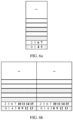
- FIG. 6a is a diagram of time-frequency resource mapping of a single-symbol type 1 DMRS according to an embodiment of this application.
- a maximum quantity of DMRS ports that may be supported is 8, and the DMRS ports are divided into two antenna port groups, and each antenna port group includes four DMRS ports.
- the first antenna port group includes DMRS ports 4, 5, 6, and 7, and the second antenna port group includes DMRS ports 0, 1, 2, and 3.
- the DMRS ports 4 and 5 in the first antenna port group correspond to a CDM group 0, and the DMRS ports 6 and 7 in the first antenna port group correspond to a CDM group 1.
- the DMRS ports 0 and 1 in the second antenna port group correspond to the CDM group 0, and the DMRS ports 2 and 3 in the second antenna port group correspond to the CDM group 1. It can be learned that the first antenna port group and the second antenna port group each correspond to two CDM groups, and a quantity of CDM groups corresponding to the first antenna port group is the same as a quantity of CDM groups corresponding to the second antenna port group. DMRSs corresponding to DMRS ports that belong to a same CDM group and that are in the first antenna port group and the second antenna port group are mapped to a same time-frequency resource.
- antenna port indexes corresponding to antenna ports included in the first antenna port group may alternatively be 8, 9, 10, and 11, and antenna port indexes corresponding to antenna ports included in the second antenna port group are 0, 1, 2, and 3.
- antenna port indexes corresponding to antenna ports included in the first antenna port group are E, F, G, and H
- antenna port indexes corresponding to antenna ports included in the second antenna port group are A, B, C, and D.
- FIG. 6b is a diagram of time-frequency resource mapping of a double-symbol type 1 DMRS according to an embodiment of this application.
- a maximum quantity of DMRS ports that may be supported is 16, and the DMRS ports are divided into two antenna port groups, and each antenna port group includes eight DMRS ports.
- the first antenna port group includes DMRS ports 8 to 15, and the second antenna port group includes DMRS ports 0 to 7.
- the DMRS ports 8, 9, 12, and 13 in the first antenna port group correspond to a CDM group 0, and the DMRS ports 10, 11, 14, and 15 in the first antenna port group correspond to a CDM group 1.
- the DMRS ports 0, 1, 4, and 5 in the second antenna port group correspond to the CDM group 0, and the DMRS ports 2, 3, 6, and 7 in the second antenna port group correspond to the CDM group 1. It can be learned that the first antenna port group and the second antenna port group each correspond to two CDM groups, and a quantity of CDM groups corresponding to the first antenna port group is the same as a quantity of CDM groups corresponding to the second antenna port group. DMRSs corresponding to DMRS ports that belong to a same CDM group and that are in the first antenna port group and the second antenna port group are mapped to a same time-frequency resource.
- antenna port indexes corresponding to antenna ports included in the first antenna port group are I, J, K, L, M, N, and O
- antenna port indexes corresponding to antenna ports included in the second antenna port group are A, B, C, D, E, F, G, and H.
- FIG. 7a is a diagram of time-frequency resource mapping of a single-symbol type 2 DMRS according to an embodiment of this application.
- a maximum quantity of DMRS ports that may be supported is 12, and the DMRS ports are divided into two antenna port groups, and each antenna port group includes six DMRS ports.
- the first antenna port group includes DMRS ports 6 to 11, and the second antenna port group includes DMRS ports 0 to 5.
- the DMRS ports 6 and 7 in the first antenna port group correspond to a CDM group 0, the DMRS ports 8 and 9 in the first antenna port group correspond to a CDM group 1, and the DMRS ports 10 and 11 in the first antenna port group correspond to a CDM group 2.
- the DMRS ports 0 and 1 in the second antenna port group correspond to the CDM group 0, the DMRS ports 2 and 3 in the second antenna port group correspond to the CDM group 1, and the DMRS ports 4 and 5 in the second antenna port group correspond to the CDM group 2. It can be learned that the first antenna port group and the second antenna port group each correspond to three CDM groups, and a quantity of CDM groups corresponding to the first antenna port group is the same as a quantity of CDM groups corresponding to the second antenna port group. DMRSs corresponding to DMRS ports that belong to a same CDM group and that are in the first antenna port group and the second antenna port group are mapped to a same time-frequency resource.
- antenna port indexes corresponding to antenna ports included in the first antenna port group may alternatively be 12, 13, 14, 15, 16, and 17, and antenna port indexes corresponding to antenna ports included in the second antenna port group are 0, 1, 2, 3, 4, and 5.
- antenna port indexes corresponding to antenna ports included in the first antenna port group are G, H, I, J, K, and L
- antenna port indexes corresponding to antenna ports included in the second antenna port group are A, B, C, D, E, and F.
- FIG. 7b is a diagram of time-frequency resource mapping of a double-symbol type 2 DMRS according to an embodiment of this application.
- a maximum quantity of DMRS ports that may be supported is 24, and the DMRS ports are divided into two antenna port groups, and each antenna port group includes 12 DMRS ports.
- the first antenna port group includes DMRS ports 12 to 23, and the second antenna port group includes DMRS ports 0 to 11.
- the DMRS ports 12, 13, 18, and 19 in the first antenna port group correspond to a CDM group 0, the DMRS ports 14, 15, 20, and 21 in the first antenna port group correspond to a CDM group 1, and the DMRS ports 16, 17, 22, and 23 in the first antenna port group correspond to a CDM group 2.
- the DMRS ports 0, 1, 6, and 7 in the second antenna port group correspond to the CDM group 0
- the DMRS ports 2, 3, 8, and 9 in the second antenna port group correspond to the CDM group 1
- the DMRS ports 4, 5, 10, and 11 in the second antenna port group correspond to the CDM group 2. It can be learned that the first antenna port group and the second antenna port group each correspond to three CDM groups, and a quantity of CDM groups corresponding to the first antenna port group is the same as a quantity of CDM groups corresponding to the second antenna port group.
- DMRSs corresponding to DMRS ports that belong to a same CDM group and that are in the first antenna port group and the second antenna port group are mapped to a same time-frequency resource.
- antenna port indexes corresponding to antenna ports included in the first antenna port group are M, N, O, P, Q, R, S, T, U, V, W, and X
- antenna port indexes corresponding to antenna ports included in the second antenna port group are A, B, C, D, E, F, G, H, I, J, K, and L.
- FIG. 6a, FIG. 6b , FIG. 7a, and FIG. 7b are merely examples of antenna port expansion designs for the single-symbol/double-symbol type 1/type 2 DMRS.
- the port index in the first antenna port group and the port index the second antenna port group are also merely examples, and there is no strict sequence relationship between the port index in the first antenna port group and the port index in the second antenna port group.
- the port index in the second antenna port group may be an existing port index
- the port index in the first antenna port group may be consecutive or inconsecutive with the port index in the second antenna port group.
- the first relationship further includes a quantity of DMRS code division multiplexing groups to which data is not mapped and that correspond to each of the at least one candidate value of the antenna port field in the DCI.
- the first relationship may be represented as a DMRS port index table. Descriptions are separately provided below.
- a total quantity of orthogonal DMRS ports that may be supported after expansion is 8.
- the orthogonal DMRS ports respectively correspond to DMRS port indexes 0 to 7. It should be noted that the port indexes 0 to 7 herein may alternatively be represented as DMRS port indexes 1000 to 1007.
- CDM group 0 For the single-symbol type 1 DMRS, two CDM groups are included: a CDM group 0 and a CDM group 1, and each CDM group includes four DMRS ports, as shown in FIG. 6a .
- the CDM group 0 includes DMRS ports 0, 1, 4, and 5, and the CDM group 1 includes DMRS ports 2, 3, 6, and 7. It can be learned that, for an unexpanded DRMS, a total of four DMRS ports are supported. Therefore, the rank 5 to the rank 8 cannot be supported. For an expanded DMRS, a total of eight DMRS ports may be supported. Therefore, a single symbol may support transmission of a maximum of the rank 8.
- supported DMRS port indexes may alternatively have another value range.
- the eight supported DMRS ports correspond to port indexes 8 to 15, that is, DMRS port indexes 0 to 7 shown in Table 19 to Table 22 may alternatively be represented as the indexes 8 to 15, where each value in the indexes 0 to 7 one-to-one corresponds to each value in the indexes 8 to 15.
- DMRS port indexes 0 to 7 shown in Table 18 to Table 21 may alternatively be represented as indexes 0 to 3 and indexes 8 to 11, that is, DMRS port indexes 4 to 7 shown in Table 18 to Table 21 may alternatively be represented as the indexes 8 to 11, where each value in the indexes 4 to 7 one-to-one corresponds to each value in the indexes 8 to 11.
- the DMRS port index table may be used for uplink/downlink transmission.
- N 5, that is, the rank is 5, and transmission of a maximum of five streams may be supported.
- a value of an antenna port when a value of an antenna port is "0", it indicates that the quantity of DMRS CDM groups to which data is not mapped is 2, where five configured DMRS antenna ports belong to two CDM groups, and a time-frequency resource corresponding to no additional CDM group is used to map data; DMRS port indexes are 0 to 4; and the quantity of front-loaded symbols is 1 (namely, the DMRS ports 0 to 4 are mapped to one symbol).
- Port indexes in the DMRS port indexes 0 to 4 may alternatively have other values of DMRS ports, for example, 0, 1, 2, 3, and 5; 0, 1, 2, 3, and 6; or 0, 1, 2, 3, and 7.
- That the value of the antenna port is "0" is an example, and the antenna port may be any value. This is not limited in this application.
- the DMRS port index table may be used for uplink/downlink transmission.
- N 6, that is, the rank is 6, and transmission of a maximum of six streams may be supported.
- DMRS port indexes are 0, 1, 2, 3, 4, and 6; and the quantity of front-loaded symbols is 1 (namely, the DMRS ports 0, 1, 2, 3, 4, and 6 are mapped to one symbol).
- Port indexes in the DMRS port indexes 0, 1, 2, 3, 4, and 6 may alternatively have other values of DMRS ports, for example, 0, 1, 2, 3, 4, and 7; 0, 1, 2, 3, 5, and 6; or 0, 1, 2, 3, 5, and 7.
- That the value of the antenna port is "0" is an example, and the antenna port may be any value. This is not limited in this application.
- the DMRS port index table may be used for uplink/downlink transmission.
- N 7, that is, the rank is 7, and transmission of a maximum of seven streams may be supported.
- DMRS port indexes are 0, 1, 2, 3, 4, 5, and 6; and the quantity of front-loaded symbols is 1 (namely, the DMRS ports 0, 1, 2, 3, 4, 5, and 6 are mapped to one symbol).
- Port indexes in the DMRS port indexes 0, 1, 2, 3, 4, 5, and 6 may alternatively have other values of DMRS ports, for example, 0, 1, 2, 3, 4, 5, and 7; 0, 1, 2, 3, 4, 6, and 7; or 0, 1, 2, 3, 5, 6, and 7.
- That the value of the antenna port is "0" is an example, and the antenna port may be any value. This is not limited in this application.
- the DMRS port index table may be used for uplink/downlink transmission.
- N 8, that is, the rank is 8, and transmission of a maximum of eight streams may be supported.
- DMRS CDM groups to which data is not mapped are 2, where eight configured DMRS antenna ports belong to two CDM groups, and a time-frequency resource corresponding to no additional CDM group is used to map data; DMRS port indexes are 0, 1, 2, 3, 4, 5, 6, and 7; and the quantity of front-loaded symbols is 1 (namely, the DMRS ports 0, 1, 2, 3, 4, 5, 6, and 7 are mapped to one symbol).
- Port indexes in the DMRS port indexes 0, 1, 2, 3, 4, 5, 6, and 7 may alternatively have other values of DMRS ports.
- That the value of the antenna port is "0" is an example, and the antenna port may be any value. This is not limited in this application.
- a total quantity of orthogonal DMRS ports that may be supported after expansion is 16.
- the orthogonal DMRS ports respectively correspond to DMRS port indexes 0 to 15. It should be noted that the port indexes 0 to 15 herein may alternatively be represented as DMRS port indexes 1000 to 1015.
- CDM group 0 For the double-symbol type 1 DMRS, two CDM groups are included: a CDM group 0 and a CDM group 1, and each CDM group includes eight DMRS ports, as shown in FIG. 6b .
- the CDM group 0 includes DMRS ports 0, 1, 4, 5, 8, 9, 12, and 13, and the CDM group 1 includes DMRS ports 2, 3, 6, 7, 10, 11, 14, and 15. It can be learned that, for an unexpanded DRMS, one CDM group supports a total of four DMRS ports. Therefore, two CDM groups are needed to support the rank 5 to the rank 8. For an expanded DMRS, one CDM group supports a total of eight DMRS ports. Therefore, only one CDM group is needed to support transmission of a maximum of the rank 8.
- supported DMRS port indexes may alternatively have another value range.
- 16 supported DMRS ports correspond to port indexes 8 to 23, that is, DMRS port indexes 0 to 15 shown in Table 23 to Table 26 may alternatively be represented as the indexes 8 to 23, where each value in the indexes 0 to 15 one-to-one corresponds to each value in the indexes 8 to 23.
- 16 supported DMRS ports respectively correspond to port indexes 0 to 7 and 8 to 15.
- the DMRS port index table may be used for uplink/downlink transmission.
- N 5, that is, the rank is 5, and transmission of a maximum of five streams may be supported.
- the value of the antenna port is "1" it indicates that the quantity of DMRS CDM groups to which data is not mapped is 1, where five configured DMRS antenna ports belong to one CDM group, and a time-frequency location corresponding to one remaining CDM group may be used to map data; DMRS port indexes are 0, 1, 4, 5, and 8; and the quantity of front-loaded symbols is 2 (namely, the DMRS ports 0, 1, 4, 5, and 8 are mapped to two symbols). It can be learned that the rank 5 is supported, and a quantity of front-loaded symbols occupied by the five configured DMRS antenna ports is 2, but only one CDM group is used, to reduce a resource requirement.
- the DMRS port indexes 0, 1, 4, 5, and 8 may alternatively have other values of DMRS ports, for example, 0, 1, 4, 5, and 9; 0, 1, 4, 5, and 12; 0, 1, 4, 5, and 13; 2, 3, 6, 7, and 10; 2, 3, 6, 7, and 11; 2, 3, 6, 7, and 14; or 2, 3, 6, 7, and 15.
- the value of the antenna port is "2"
- the quantity of DMRS CDM groups to which data is not mapped is 2, where five configured DMRS antenna ports belong to two CDM groups, and a time-frequency resource corresponding to no additional CDM group is used to map data; DMRS port indexes are 0 to 4; and the quantity of front-loaded symbols is 1 (namely, the DMRS ports 0 to 4 are mapped to one symbol).
- the rank 5 is supported, but mapping needs to be performed only on one symbol, to reduce symbol overheads.
- Port indexes in the DMRS port indexes 0 to 4 may alternatively have other values of DMRS ports, for example, 0, 1, 2, 3, and 5, 0, 1, 2, 3, and 6, or 0, 1, 2, 3, and 7.
- the value of the antenna port is an example and may be any value. This is not limited in this application.
- the table may include all rows corresponding to the values "0", “1", and “2", or may include a row corresponding to one or more of the values "0", “1", and “2".
- the DMRS port index table may be used for uplink/downlink transmission.
- N 6, that is, the rank is 6, and transmission of a maximum of six streams may be supported.
- the value of the antenna port is "1"
- the quantity of DMRS CDM groups to which data is not mapped is 1, where six configured DMRS antenna ports are divided into one CDM group, and a time-frequency resource corresponding to one remaining CDM group may be used to map data; DMRS port indexes are 0, 1, 4, 5, 8, and 9; and the quantity of front-loaded symbols is 2 (namely, the DMRS ports 0, 1, 4, 5, 8, and 9 are mapped to two symbols). It can be learned that the rank 6 is supported, and a quantity of front-loaded symbols occupied by the six configured DMRS antenna ports is 2, but only one CDM group is used, to reduce a resource requirement.
- Port indexes in the DMRS port indexes 0, 1, 4, 5, 8, and 9 may alternatively have other values of DMRS ports, for example, 0, 1, 4, 5, 12, and 13; 0, 1, 4, 5, 8, and 12; 0, 1, 4, 5, 9, and 13; 2, 3, 6, 7, 10, and 11; 2, 3, 6, 7, 14, and 15; 2, 3, 6, 7, 10, and 14; or 2, 3, 6, 7, 11, and 15.
- the value of the antenna port is "2"
- the quantity of DMRS CDM groups to which data is not mapped is 2, where six configured DMRS antenna ports belong to two CDM groups, and a time-frequency resource corresponding to no additional CDM group is used to map data; DMRS port indexes are 0, 1, 2, 3, 4, and 6; and the quantity of front-loaded symbols is 1 (namely, the DMRS ports 0, 1, 2, 3, 4, and 6 are mapped to one symbol). It can be learned that the rank 6 is supported, but mapping needs to be performed only on one symbol, to reduce symbol overheads.
- Port indexes in the DMRS port indexes 0, 1, 2, 3, 4, and 6 may alternatively have other values of DMRS ports, for example, 0, 1, 2, 3, 4, and 7; 0, 1, 2, 3, 5, and 6; or 0, 1, 2, 3, 5, and 7.
- the value of the antenna port is an example and may be any value. This is not limited in this application.
- the table may include all rows corresponding to the values "0", “1", and “2", or may include a row corresponding to one or more of the values "0", “1", and “2".
- the DMRS port index table may be used for uplink/downlink transmission.
- N 7, that is, the rank is 7, and transmission of a maximum of seven streams may be supported.
- the value of the antenna port is "1" it indicates that the quantity of DMRS CDM groups to which data is not mapped is 1, where seven configured DMRS antenna ports belong to one CDM group, and a time-frequency resource corresponding to one remaining CDM group may be used to map data; DMRS port indexes are 0, 1, 4, 5, 8, 9, and 12; and the quantity of front-loaded symbols is 2 (namely, the DMRS ports 0, 1, 4, 5, 8, 9 and 12 are mapped to two symbols). It can be learned that the rank 7 is supported, and a quantity of front-loaded symbols occupied by the seven configured DMRS antenna ports is 2, but only one CDM group is used, to reduce a resource requirement.
- Port indexes in the DMRS port indexes 0, 1, 4, 5, 8, 9, and 12 may alternatively have other values of DMRS ports, for example, 0, 1, 4, 5, 8, 9, and 13; 0, 1, 4, 5, 8, 12, and 13; 0, 1, 4, 5, 9, 12, and 13; 2, 3, 6, 7, 10, 11, and 14; 2, 3, 6, 7, 10, 11, and 15; 2, 3, 6, 7, 10, 14, and 15; or 2, 3, 6, 7, 11, 14, and 15.
- the value of the antenna port is "2"
- the quantity of DMRS CDM groups to which data is not mapped is 2, where seven configured DMRS antenna ports belong to two CDM groups, and a time-frequency resource corresponding to no additional CDM group is used to map data; DMRS port indexes are 0, 1, 2, 3, 4, 5, and 6; and the quantity of front-loaded symbols is 1 (namely, the DMRS ports 0, 1, 2, 3, 4, 5, and 6 are mapped to one symbol).
- Port indexes in the DMRS port indexes 0, 1, 2, 3, 4, 5, and 6 may alternatively have other values of DMRS ports, for example, 0, 1, 2, 3, 4, 5, and 7; 0, 1, 2, 3, 4, 6, and 7; or 0, 1, 2, 3, 5, 6, and 7.
- the value of the antenna port is an example and may be any value. This is not limited in this application.
- the table may include all rows corresponding to the values "0", “1", and “2", or may include a row corresponding to one or more of the values "0", “1", and “2".
- the DMRS port index table may be used for uplink/downlink transmission.
- N 8, that is, the rank is 8, and transmission of a maximum of eight streams may be supported.
- the value of the antenna port is "1" it indicates that the quantity of DMRS CDM groups to which data is not mapped is 1, where eight configured DMRS antenna ports belong to one CDM group, and a time-frequency resource corresponding to one remaining CDM group may be used to map data; DMRS port indexes are 0, 1, 4, 5, 8, 9, 12, and 13; and the quantity of front-loaded symbols is 2 (namely, the DMRS ports 0, 1, 4, 5, 8, 9 12, and 13 are mapped to two symbols). It can be learned that the rank 8 is supported, and a quantity of front-loaded symbols occupied by the eight configured DMRS antenna ports is 2, but only one CDM group is used, to reduce a resource requirement. Port indexes in the DMRS port indexes 0, 1, 4, 5, 8, 9, 12, and 13 may alternatively have other values of DMRS ports, for example, 2, 3, 6, 7, 10, 11, 14, and 15.
- the value of the antenna port is "2"
- the quantity of DMRS CDM groups to which data is not mapped is 2, where eight configured DMRS antenna ports belong to two CDM groups, and a time-frequency resource corresponding to no additional CDM group is used to map data; DMRS port indexes are 0, 1, 2, 3, 4, 5, 6, and 7; and the quantity of front-loaded symbols is 1 (namely, the DMRS ports 0, 1, 2, 3, 4, 5, 6, and 7 are mapped to one symbol). It can be learned that the rank 7 is supported, but mapping needs to be performed only on one symbol, to reduce symbol overheads.
- the value of the antenna port is an example and may be any value. This is not limited in this application.
- the table may include all rows corresponding to the values "0", “1", and “2", or may include a row corresponding to one or more of the values "0", "1", and "2".
- a total quantity of orthogonal DMRS ports that may be supported after expansion is 12.
- the orthogonal DMRS ports respectively correspond to DMRS port indexes 0 to 11. It should be noted that the port indexes 0 to 11 herein may alternatively be represented as DMRS port indexes 1000 to 1011.
- each CDM group includes four DMRS ports, as shown in FIG. 7a .
- the CDM group 0 includes DMRS ports 0, 1, 6, and 7, the CDM group 1 includes DMRS ports 2, 3, 8, and 9, and the CDM group 2 includes DMRS ports 4, 5, 10, and 11. It can be learned that, for an unexpanded DRMS, one CDM group supports a total of two DMRS ports. Therefore, the rank 5 to the rank 8 cannot be supported. At least three CDM groups are needed to support the rank 5 and the rank 6. For an expanded DMRS, one CDM group supports a total of four DMRS ports.
- supported DMRS port indexes may alternatively have another value range.
- the 12 supported DMRS ports correspond to port indexes 12 to 23, that is, DMRS port indexes 0 to 11 shown in Table 27 to Table 30 may alternatively be represented as the indexes 12 to 23, where each value in the indexes 0 to 11 one-to-one corresponds to each value in the indexes 12 to 23.
- the 12 supported DMRS ports respectively correspond to port indexes 0 to 5 and 12 to 17, that is, DMRS port indexes 6 to 11 shown in Table 26 to Table 29 may alternatively be represented as the indexes 12 to 17, where each value in the indexes 6 to 11 one-to-one corresponds to each value in the indexes 12 to 17.
- the DMRS port index table may be used for uplink/downlink transmission.
- N 5, that is, the rank is 5, and transmission of a maximum of five streams may be supported.
- a value of an antenna port when a value of an antenna port is "0", it indicates that the quantity of DMRS CDM groups to which data is not mapped is 3, where five configured DMRS antenna ports belong to three CDM groups, and a time-frequency resource corresponding to no additional CDM group is used to map data; DMRS port indexes are 0 to 4; and the quantity of front-loaded symbols is 1 (namely, the DMRS ports 0 to 4 are mapped to one symbol). It can be learned that the rank 5 is supported, but mapping needs to be performed only on one symbol, to reduce symbol overheads. Port indexes in the DMRS port indexes 0 to 4 may alternatively have other values of DMRS ports, for example, 0, 1, 2, 3, and 5.
- the value of the antenna port is "1"
- the quantity of DMRS CDM groups to which data is not mapped is 2, where five configured DMRS antenna ports belong to two CDM groups, and a time-frequency resource corresponding to one remaining CDM group may be used to map data; DMRS port indexes are 0, 1, 2, 3, and 6; and the quantity of front-loaded symbols is 1 (namely, the DMRS ports 0, 1, 2, 3, and 6 are mapped to one symbol).
- the rank 5 is supported, a quantity of front-loaded symbols occupied by the five configured DMRS antenna ports is 1, and only two CDM groups are used, to reduce a resource requirement.
- mapping needs to be performed only on one symbol, to reduce symbol overheads.
- Port indexes in the DMRS port indexes 0, 1, 2, 3, and 6 may alternatively have other values of DMRS ports, for example, 0, 1, 2, 3, and 7; 0, 1, 2, 3, and 8; or 0, 1, 2, 3, and 9.
- the table may include both rows corresponding to the values "0" and “1", or may include a row corresponding to one or more of the values "0" and "1".
- the DMRS port index table may be used for uplink/downlink transmission.
- N 6, that is, the rank is 6, and transmission of a maximum of six streams may be supported.
- the value of the antenna port is "1"
- the quantity of DMRS CDM groups to which data is not mapped is 2, where six configured DMRS antenna ports belong to two CDM groups, and a time-frequency resource corresponding to one remaining CDM group may be used to map data; DMRS port indexes are 0, 1, 2, 3, 6, and 8; and the quantity of front-loaded symbols is 1 (namely, the DMRS ports 0, 1, 2, 3, 6, and 8 are mapped to one symbol).
- the rank 6 is supported, a quantity of front-loaded symbols occupied by the six configured DMRS antenna ports is 1, and only two CDM groups are used, to reduce a resource requirement.
- mapping needs to be performed only on one symbol, to reduce symbol overheads.
- Port indexes in the DMRS port indexes 0, 1, 2, 3, 6, and 8 may alternatively have other values of DMRS ports, for example, 0, 1, 2, 3, 7, and 9; 0, 1, 2, 3, 6, and 7; or 0, 1, 2, 3, 8, and 9.
- the value of the antenna port is an example and may be any value. This is not limited in this application.
- the table may include both rows corresponding to the values "0" and “1", or may include a row corresponding to one or more of the values "0" and “1".
- the DMRS port index table may be used for uplink/downlink transmission.
- N 7, that is, the rank is 7, and transmission of a maximum of seven streams may be supported.
- Port indexes in the DMRS port indexes 0, 1, 2, 3, 4, 5, and 6 may alternatively have other values of DMRS ports, for example, 0, 1, 2, 3, 4, 5, and 7; 0, 1, 2, 3, 4, 5, and 8; 0, 1, 2, 3, 4, 5, and 9; 0, 1, 2, 3, 4, 5, and 10; or 0, 1, 2, 3, 4, 5, and 11.
- the value of the antenna port is "1"
- the quantity of DMRS CDM groups to which data is not mapped is 2, where seven configured DMRS antenna ports belong to two CDM groups, and a time-frequency resource corresponding to one remaining CDM group may be used to map data; DMRS port indexes are 0, 1, 2, 3, 6, 7, and 8; and the quantity of front-loaded symbols is 1 (namely, the DMRS ports 0, 1, 2, 3, 6, 7, and 8 are mapped to one symbol).
- the rank 7 is supported, a quantity of front-loaded symbols occupied by the seven configured DMRS antenna ports is 1, and only two CDM groups are used, to reduce a resource requirement.
- mapping needs to be performed only on one symbol, to reduce symbol overheads.
- Port indexes in the DMRS port indexes 0, 1, 2, 3, 6, 7, and 8 may alternatively have other values of DMRS ports, for example, 0, 1, 2, 3, 6, 7, and 9; 0, 1, 2, 3, 6, 8, and 9; or 0, 1, 2, 3, 7, 8, and 9.
- the value of the antenna port is an example and may be any value. This is not limited in this application.
- the table may include both rows corresponding to the values "0" and “1", or may include a row corresponding to one or more of the values "0" and “1".
- the DMRS port index table may be used for uplink/downlink transmission.
- N 8, that is, the rank is 8, and transmission of a maximum of eight streams may be supported.
- Port indexes in the DMRS port indexes 0, 1, 2, 3, 4, 5, 6, and 8 may alternatively have other values of DMRS ports, for example, 0, 1, 2, 3, 4, 5, 7, and 9; 0, 1, 2, 3, 4, 5, 8, and 10; 0, 1, 2, 3, 4, 5, 9, and 11; 0, 1, 2, 3, 4, 5, 6, and 10; or 0, 1, 2, 3, 4, 5, 7, and 11.
- the value of the antenna port is "1" it indicates that the quantity of DMRS CDM groups to which data is not mapped is 2, where eight configured DMRS antenna ports belong to two CDM groups, and a time-frequency resource corresponding to one remaining CDM group may be used to map data; DMRS port indexes are 0, 1, 2, 3, 6, 7, 8, and 9; and the quantity of front-loaded symbols is 1 (namely, the DMRS ports 0, 1, 2, 3, 6, 7, 8, and 9 are mapped to one symbol). It can be learned that the rank 8 is supported, a quantity of front-loaded symbols occupied by the eight configured DMRS antenna ports is 1, but only two CDM groups are used, to reduce a resource requirement. In addition, mapping needs to be performed only on one symbol, to reduce symbol overheads.
- the value of the antenna port is an example and may be any value. This is not limited in this application.
- the table may include both rows corresponding to the values "0" and “1", or may include a row corresponding to one or more of the values "0" and "1".
- a total quantity of orthogonal DMRS ports that may be supported after expansion is 24.
- the orthogonal DMRS ports respectively correspond to DMRS port indexes 0 to 23. It should be noted that the port indexes 0 to 23 herein may alternatively be represented as DMRS port indexes 1000 to 1023.
- each CDM group includes eight DMRS ports, as shown in FIG. 7b .
- the CDM group 0 includes DMRS ports 0, 1, 6, 7, 12, 13, 18, and 19, the CDM group 1 includes DMRS ports 2, 3, 8, 9, 14, 15, 20, and 21, and the CDM group 2 includes DMRS ports 4, 5, 10, 11, 16, 17, 22, and 23. It can be learned that, for an unexpanded DRMS, one CDM group supports a total of four DMRS ports. Therefore, at least two CDM groups are needed to support the rank 5 to the rank 8.
- one CDM group supports a total of eight DMRS ports. Therefore, one CDM group may support transmission of a maximum of the rank 8.
- supported DMRS port indexes may alternatively have another value range.
- the 24 supported DMRS ports correspond to port indexes 12 to 35, that is, DMRS port indexes 0 to 23 shown in Table 31 to Table 34 may alternatively be represented as the indexes 12 to 35, where each value in the indexes 0 to 23 one-to-one corresponds to each value in the indexes 12 to 35.
- the 24 supported DMRS ports respectively correspond to port indexes 0 to 11 and 12 to 23.
- the DMRS port index table may be used for uplink/downlink transmission.
- N 5, that is, the rank is 5, and transmission of a maximum of five streams may be supported.
- the value of the antenna port is "1"
- the quantity of DMRS CDM groups to which data is not mapped is 2, where five configured DMRS antenna ports belong to two CDM groups, and a time-frequency resource corresponding to one remaining CDM group may be used to map data; DMRS port indexes are 0, 1, 2, 3, and 6; and the quantity of front-loaded symbols is 2 (namely, the DMRS ports 0, 1, 2, 3, and 6 are mapped to two symbols). It can be learned that the rank 5 is supported, and a quantity of front-loaded symbols occupied by the five configured DMRS antenna ports is 2, but only two CDM groups are used, to reduce a resource requirement.
- the value of the antenna port is "2"
- the quantity of DMRS CDM groups to which data is not mapped is 2, where five configured DMRS antenna ports belong to two CDM groups, and a time-frequency resource corresponding to one remaining CDM group may be used to map data; DMRS port indexes are 0, 1, 2, 3, and 6; and the quantity of front-loaded symbols is 1 (namely, the DMRS ports 0, 1, 2, 3, and 6 are mapped to one symbol).
- the rank 5 is supported, a quantity of front-loaded symbols occupied by the five configured DMRS antenna ports is 1, and only two CDM groups are used, to reduce a resource requirement.
- mapping needs to be performed only on one symbol, to reduce symbol overheads.
- Port indexes in the DMRS port indexes 0, 1, 2, 3, and 6 may alternatively have other values of DMRS ports, for example, 0, 1, 2, 3, and 7; 0, 1, 2, 3, and 8; or 0, 1, 2, 3, and 9.
- the value of the antenna port is "3"
- the quantity of DMRS CDM groups to which data is not mapped is 1, where five configured DMRS antenna ports belong to one CDM group, and time-frequency resources corresponding to two remaining CDM groups may be used to map data; DMRS port indexes are 0, 1, 6, 7, and 12; and the quantity of front-loaded symbols is 2 (namely, the DMRS ports 0, 1, 6, 7, and 12 are mapped to two symbols). It can be learned that the rank 5 is supported, and a quantity of front-loaded symbols occupied by the five configured DMRS antenna ports is 2, but only one CDM group is used, to reduce a resource requirement.
- Port indexes in the DMRS port indexes 0, 1, 6, 7, and 12 may alternatively have other values of DMRS ports, for example, 0, 1, 6, 7, and 13; 0, 1, 6, 7, and 18; or 0, 1, 6, 7, and 19.
- the value of the antenna port is an example and may be any value. This is not limited in this application.
- the table may include all rows corresponding to the values "0", “1”, “2”, and “3", or may include a row corresponding to one or more of the values “0", “1", “2”, and “3”.
- the DMRS port index table may be used for uplink/downlink transmission.
- N 6, that is, the rank is 6, and transmission of a maximum of six streams may be supported.
- the value of the antenna port is "1"
- the quantity of DMRS CDM groups to which data is not mapped is 2, where six configured DMRS antenna ports belong to two CDM groups, and a time-frequency resource corresponding to one remaining CDM group may be used to map data; DMRS port indexes are 0, 1, 2, 3, 6, and 8; and the quantity of front-loaded symbols is 2 (namely, the DMRS ports 0, 1, 2, 3, 6, and 8 are mapped to two symbols). It can be learned that the rank 6 is supported, and a quantity of front-loaded symbols occupied by the six configured DMRS antenna ports is 2, but only two CDM groups are used, to reduce a resource requirement.
- the value of the antenna port is "2"
- the quantity of DMRS CDM groups to which data is not mapped is 2, where six configured DMRS antenna ports belong to two CDM groups, and a time-frequency resource corresponding to one remaining CDM group may be used to map data; DMRS port indexes are 0, 1, 2, 3, 6, and 8; and the quantity of front-loaded symbols is 1 (namely, the DMRS ports 0, 1, 2, 3, 6, and 8 are mapped to one symbol).
- the rank 6 is supported, a quantity of front-loaded symbols occupied by the six configured DMRS antenna ports is 1, and only two CDM groups are used, to reduce a resource requirement.
- mapping needs to be performed only on one symbol, to reduce symbol overheads.
- Port indexes in the DMRS port indexes 0, 1, 2, 3, 6, and 8 may alternatively have other values of DMRS ports, for example, 0, 1, 2, 3, 7, and 9; 0, 1, 2, 3, 6, and 7; or 0, 1, 2, 3, 8, and 9.
- the value of the antenna port is "3"
- the quantity of DMRS CDM groups to which data is not mapped is 1, where six configured DMRS antenna ports belong to one CDM group, and time-frequency resources corresponding to two remaining CDM groups may be used to map data; DMRS port indexes are 0, 1, 6, 7, 12, and 13; and the quantity of front-loaded symbols is 2 (namely, the DMRS ports 0, 1, 6, 7, 12, and 13 are mapped to two symbols). It can be learned that the rank 6 is supported, and a quantity of front-loaded symbols occupied by the six configured DMRS antenna ports is 2, but only one CDM group is used, to reduce a resource requirement.
- Port indexes in the DMRS port indexes 0, 1, 6, 7, 12, and 13 may alternatively have other values of DMRS ports, for example, 0, 1, 6, 7, 18, and 19; 0, 1, 6, 7, 12, and 18; 0, 1, 6, 7, 13, and 19; 0, 1, 6, 7, 12, and 19; or 0, 1, 6, 7, 13, and 18.
- the value of the antenna port is an example and may be any value. This is not limited in this application.
- the table may include all rows corresponding to the values "0", “1", “2”, and “3", or may include a row corresponding to one or more of the values “0", “1", “2”, and “3”.
- the DMRS port index table may be used for uplink/downlink transmission.
- N 7, that is, the rank is 7, and transmission of a maximum of seven streams may be supported.
- the value of the antenna port is "1"
- the quantity of DMRS CDM groups to which data is not mapped is 2, where seven configured DMRS antenna ports belong to two CDM groups, and a time-frequency resource corresponding to one remaining CDM group may be used to map data; DMRS port indexes are 0, 1, 2, 3, 6, 7, and 8; and the quantity of front-loaded symbols is 1 (namely, the DMRS ports 0, 1, 2, 3, 6, 7, and 8 are mapped to one symbol).
- Port indexes in the DMRS port indexes 0, 1, 2, 3, 6, 7, and 8 may alternatively have other values of DMRS ports, for example, 0, 1, 2, 3, 6, 7, and 9; 0, 1, 2, 3, 6, 8, and 9; or 0, 1, 2, 3, 7, 8, and 9.
- the value of the antenna port is "2"
- the quantity of DMRS CDM groups to which data is not mapped is 1, where seven configured DMRS antenna ports belong to one CDM group, and time-frequency resources corresponding to two remaining CDM groups may be used to map data; DMRS port indexes are 0, 1, 6, 7, 12, 13, and 18; and the quantity of front-loaded symbols is 2 (namely, the DMRS ports 0, 1, 6, 7, 12, 13, and 18 are mapped to two symbols).
- the rank 7 is supported, and a quantity of front-loaded symbols occupied by the seven configured DMRS antenna ports is 2, but only one CDM group is used, to reduce a resource requirement.
- Port indexes in the DMRS port indexes 0, 1, 6, 7, 12, 13, and 18 may alternatively have other values of DMRS ports, for example, 0, 1, 6, 7, 12, 13, and 19; 0, 1, 6, 7, 12, 18, and 19; or 0, 1, 6, 7, 13, 18, and 19.
- the value of the antenna port is an example and may be any value. This is not limited in this application.
- the table may include all rows corresponding to the values "0", “1", and “2", or may include a row corresponding to one or more of the values "0", “1", and “2".
- the DMRS port index table may be used for uplink/downlink transmission.
- N 8, that is, the rank is 8, and transmission of a maximum of eight streams may be supported.
- the value of the antenna port is "1"
- the quantity of DMRS CDM groups to which data is not mapped is 2, where eight configured DMRS antenna ports belong to two CDM groups, and a time-frequency resource corresponding to one remaining CDM group may be used to map data; DMRS port indexes are 0, 1, 2, 3, 6, 7, and 8; and the quantity of front-loaded symbols is 1 (namely, the DMRS ports 0, 1, 2, 3, 6, 7, and 8 are mapped to one symbol).
- the rank 8 is supported, but mapping needs to be performed only on one symbol, to reduce symbol overheads.
- only two CDM groups are used, to reduce a resource requirement.
- the value of the antenna port is "2"
- the quantity of DMRS CDM groups to which data is not mapped is 1, where eight configured DMRS antenna ports belong to one CDM group, and time-frequency resources corresponding to two remaining CDM groups may be used to map data; DMRS port indexes are 0, 1, 6, 7, 12, 13, 18, and 19; and the quantity of front-loaded symbols is 2 (namely, the DMRS ports 0, 1, 6, 7, 12, 13, 18, and 19 are mapped to two symbols). It can be learned that the rank 8 is supported, and a quantity of front-loaded symbols occupied by the eight configured DMRS antenna ports is 2, but only one CDM group is used, to reduce a resource requirement.
- the table may include all rows corresponding to the values "0", “1", and “2", or may include a row corresponding to one or more of the values "0", "1", and "2".
- the DMRS port index table corresponding to the single symbol and the type 1 may be further shown in Table 35.
- This table may indicate ports for downlink DMRS transmission.
- the value of the antenna port is "1" it indicates that the quantity of DMRS CDM groups to which data is not mapped is 2, where six configured DMRS antenna ports belong to two CDM groups, and a time-frequency resource corresponding to no additional CDM group is used to map data; and DMRS port indexes are 0, 1, 2, 3, 4, and 6.
- the value of the antenna port is "2"
- it indicates that the quantity of DMRS CDM groups to which data is not mapped is 2, where seven configured DMRS antenna ports belong to two CDM groups, and a time-frequency resource corresponding to no additional CDM group is used to map data; and DMRS port indexes are 0, 1, 2, 3, 4, 5, and 6.
- the value of the antenna port is "3"
- it indicates that the quantity of DMRS CDM groups to which data is not mapped is 2, where eight configured DMRS antenna ports belong to two CDM groups, and a time-frequency resource corresponding to no additional CDM group is used to map data; and DMRS port indexes are 0, 1, 2, 3, 4, 5, 6, and 7.
- the value of the antenna port is an example and may be any value. This is not limited in this application.
- the table may include all rows corresponding to the values "0”, “1”, “2”, and “3”, or may include a row corresponding to one or more of the values "0", “1", “2”, and "3".
- the DMRS port index table corresponding to the double symbol and the type 2 may be further shown in Table 36.
- This table may indicate ports for downlink DMRS transmission.
- the value of the antenna port is "1" it indicates that the quantity of DMRS CDM groups to which data is not mapped is 2, where six configured DMRS antenna ports belong to two CDM groups, and a time-frequency resource corresponding to no additional CDM group is used to map data; DMRS port indexes are 0, 1, 2, 3, 4, and 6; and the quantity of front-loaded symbols is 2 (namely, the DMRS ports 0, 1, 2, 3, 4, and 6 are mapped to two symbols).
- the value of the antenna port is "2"
- the quantity of DMRS CDM groups to which data is not mapped is 2, where seven configured DMRS antenna ports belong to two CDM groups, and a time-frequency resource corresponding to no additional CDM group is used to map data; DMRS port indexes are 0, 1, 2, 3, 4, 5, and 6; and the quantity of front-loaded symbols is 2 (namely, the DMRS ports 0, 1, 2, 3, 4, 5, and 6 are mapped to two symbols).
- the value of the antenna port is "3"
- the quantity of DMRS CDM groups to which data is not mapped is 2, where eight configured DMRS antenna ports belong to two CDM groups, and a time-frequency resource corresponding to no additional CDM group is used to map data; DMRS port indexes are 0, 1, 2, 3, 4, 5, 6, and 7; and the quantity of front-loaded symbols is 2 (namely, the DMRS ports 0, 1, 2, 3, 4, 5, 6, and 7 are mapped to two symbols).
- the value of the antenna port is "4", it indicates that the quantity of DMRS CDM groups to which data is not mapped is 1, where five configured DMRS antenna ports belong to one CDM group, and a time-frequency resource corresponding to one remaining CDM group may be used to map data; DMRS port indexes are 0, 1, 4, 5, and 8; and the quantity of front-loaded symbols is 2 (namely, the DMRS ports 0, 1, 4, 5, and 8 are mapped to two symbols). It can be learned that the rank 5 is supported, but only one CDM group is used, to reduce a resource requirement.
- the value of the antenna port is "5", it indicates that the quantity of DMRS CDM groups to which data is not mapped is 1, where six configured DMRS antenna ports belong to one CDM group, and a time-frequency resource corresponding to one remaining CDM group may be used to map data; DMRS port indexes are 0, 1, 4, 5, 8, and 9; and the quantity of front-loaded symbols is 2 (namely, the DMRS ports 0, 1, 4, 5, 8, and 9 are mapped to two symbols). It can be learned that the rank 6 is supported, but only one CDM group is used, to reduce a resource requirement.
- the value of the antenna port is "6"
- the quantity of DMRS CDM groups to which data is not mapped is 1, where seven configured DMRS antenna ports belong to one CDM group, and a time-frequency resource corresponding to one remaining CDM group may be used to map data; DMRS port indexes are 0, 1, 4, 5, 8, 9, and 12; and the quantity of front-loaded symbols is 2 (namely, the DMRS ports 0, 1, 4, 5, 8, 9, and 12 are mapped to two symbols). It can be learned that the rank 7 is supported, but only one CDM group is used, to reduce a resource requirement.
- the value of the antenna port is "7"
- the quantity of DMRS CDM groups to which data is not mapped is 1, where eight configured DMRS antenna ports belong to one CDM group, and a time-frequency resource corresponding to one remaining CDM group may be used to map data; DMRS port indexes are 0, 1, 4, 5, 8, 9, 12, and 13; and the quantity of front-loaded symbols is 2 (namely, the DMRS ports 0, 1, 4, 5, 8, 9, 12, and 13 are mapped to two symbols). It can be learned that the rank 8 is supported, but only one CDM group is used, to reduce a resource requirement.
- the value of the antenna port is "8" it indicates that the quantity of DMRS CDM groups to which data is not mapped is 2, where five configured DMRS antenna ports belong to two CDM groups, and a time-frequency resource corresponding to no additional CDM group is used to map data; DMRS port indexes are 0 to 4; and the quantity of front-loaded symbols is 1 (namely, the DMRS ports 0 to 4 are mapped to one symbol). It can be learned that the rank 5 is supported, but mapping is performed only on one symbol, to reduce symbol overheads.
- the value of the antenna port is "9"
- the quantity of DMRS CDM groups to which data is not mapped is 2, where six configured DMRS antenna ports belong to two CDM groups, and a time-frequency resource corresponding to no additional CDM group is used to map data; DMRS port indexes are 0, 1, 2, 3, 4, and 6; and the quantity of front-loaded symbols is 1 (namely, the DMRS ports 0, 1, 2, 3, 4, and 6 are mapped to one symbol). It can be learned that the rank 6 is supported, but mapping is performed only on one symbol, to reduce symbol overheads.
- the value of the antenna port is "10"
- the quantity of DMRS CDM groups to which data is not mapped is 2, where seven configured DMRS antenna ports belong to two CDM groups, and a time-frequency resource corresponding to no additional CDM group is used to map data, DMRS port indexes are 0, 1, 2, 3, 4, 5, and 6; and the quantity of front-loaded symbols is 1 (namely, the DMRS ports 0, 1, 2, 3, 4, 5, and 6 are mapped to one symbol). It can be learned that the rank 6 is supported, but mapping is performed only on one symbol, to reduce symbol overheads.
- the value of the antenna port is "11" it indicates that the quantity of DMRS CDM groups to which data is not mapped is 2, where eight configured DMRS antenna ports belong to two CDM groups, and a time-frequency resource corresponding to no additional CDM group is used to map data; DMRS port indexes are 0, 1, 2, 3, 4, 5, 6, and 7; and the quantity of front-loaded symbols is 1 (namely, the DMRS ports 0, 1, 2, 3, 4, 5, 6, and 7 are mapped to one symbol). It can be learned that the rank 8 is supported, but mapping is performed only on one symbol, to reduce symbol overheads.
- the value of the antenna port is an example and may be any value. This is not limited in this application.
- the table may include all rows corresponding to the values "0" to “11", or may include a row corresponding to one or more of the values "0" to "11".
- This table may indicate ports for downlink DMRS transmission.
- the value of the antenna port is "1" it indicates that the quantity of DMRS CDM groups to which data is not mapped is 3, where six configured DMRS antenna ports belong to three CDM groups, and a time-frequency resource corresponding to no additional CDM group is used to map data; and DMRS port indexes are 0 to 5.
- the value of the antenna port is "2"
- the quantity of DMRS CDM groups to which data is not mapped is 2, where five configured DMRS antenna ports belong to two CDM groups, and a time-frequency resource corresponding to one remaining CDM group may be used to map data; and DMRS port indexes are 0, 1, 2, 3, and 6. It can be learned that the rank 5 is supported, but only two CDM groups are occupied, to reduce a resource requirement.
- the value of the antenna port is "3"
- the quantity of DMRS CDM groups to which data is not mapped is 2, where six configured DMRS antenna ports belong to two CDM groups, and a time-frequency resource corresponding to one remaining CDM group may be used to map data; and DMRS port indexes are 0, 1, 2, 3, 6, and 8. It can be learned that the rank 6 is supported, but only two CDM groups are occupied, to reduce a resource requirement.
- the antenna port When the value of the antenna port is "4", it indicates that the quantity of DMRS CDM groups to which data is not mapped is 3, where seven configured DMRS antenna ports belong to three CDM groups, and a time-frequency resource corresponding to no additional CDM group is used to map data; and DMRS port indexes are 0, 1, 2, 3, 4, 5, and 6.
- the value of the antenna port is "5", it indicates that the quantity of DMRS CDM groups to which data is not mapped is 2, where seven configured DMRS antenna ports belong to two CDM groups, and a time-frequency resource corresponding to one remaining CDM group may be used to map data; and DMRS port indexes are 0, 1, 2, 3, 6, 7, and 8. It can be learned that the rank 7 is supported, but only two CDM groups are occupied, to reduce a resource requirement.
- the value of the antenna port is "6"
- it indicates that the quantity of DMRS CDM groups to which data is not mapped is 3, where eight configured DMRS antenna ports belong to three CDM groups, and a time-frequency resource corresponding to no additional CDM group is used to map data; and DMRS port indexes are 0, 1, 2, 3, 4, 5, 6, and 8.
- the value of the antenna port is "7"
- the quantity of DMRS CDM groups to which data is not mapped is 2, where eight configured DMRS antenna ports belong to two CDM groups, and a time-frequency resource corresponding to one remaining CDM group may be used to map data; and DMRS port indexes are 0, 1, 2, 3, 6, 7, 8, and 9. It can be learned that the rank 8 is supported, but only two CDM groups are occupied, to reduce a resource requirement.
- the value of the antenna port is an example and may be any value. This is not limited in this application.
- the table may include all rows corresponding to the values "0" to “8", or may include a row corresponding to one or more of the values "0" to “8".
- the DMRS port index table corresponding to the double symbol and the type 2 may be further shown in Table 38.
- This table may indicate ports for downlink DMRS transmission.
- the value of the antenna port is "1" it indicates that the quantity of DMRS CDM groups to which data is not mapped is 3, where six configured DMRS antenna ports belong to three CDM groups, and a time-frequency resource corresponding to no additional CDM group is used to map data; DMRS port indexes are 0 to 5; and the quantity of front-loaded symbols is 1 (namely, the DMRS ports 0 to 5 are mapped to one symbol). It can be learned that the rank 6 is supported, but mapping is performed only on one symbol, to reduce symbol overheads.
- the value of the antenna port is "2"
- the quantity of DMRS CDM groups to which data is not mapped is 2, where five configured DMRS antenna ports belong to two CDM groups, and a time-frequency resource corresponding to one remaining CDM group may be used to map data; DMRS port indexes are 0, 1, 2, 3, and 6; and the quantity of front-loaded symbols is 2 (namely, the DMRS ports 0, 1, 2, 3, and 6 are mapped to two symbols). It can be learned that the rank 5 is supported, but only two CDM groups are occupied, to reduce a resource requirement.
- the value of the antenna port is "3"
- the quantity of DMRS CDM groups to which data is not mapped is 2, where six configured DMRS antenna ports belong to two CDM groups, and a time-frequency resource corresponding to one remaining CDM group may be used to map data; DMRS port indexes are 0, 1, 2, 3, 6, and 8; and the quantity of front-loaded symbols is 2 (namely, the DMRS ports 0, 1, 2, 3, 6, and 8 are mapped to two symbols). It can be learned that the rank 6 is supported, but only two CDM groups are occupied, to reduce a resource requirement.
- the value of the antenna port is "4", it indicates that the quantity of DMRS CDM groups to which data is not mapped is 2, where seven configured DMRS antenna ports belong to two CDM groups, and a time-frequency resource corresponding to one remaining CDM group may be used to map data; DMRS port indexes are 0, 1, 2, 3, 6, 7, and 8; and the quantity of front-loaded symbols is 2 (namely, the DMRS ports 0, 1, 2, 3, 6, 7, and 8 are mapped to two symbols). It can be learned that the rank 7 is supported, but only two CDM groups are used, to reduce a resource requirement.
- the value of the antenna port is "5", it indicates that the quantity of DMRS CDM groups to which data is not mapped is 2, where eight configured DMRS antenna ports belong to two CDM groups, and a time-frequency resource corresponding to one remaining CDM group may be used to map data; DMRS port indexes are 0, 1, 2, 3, 6, 7, 8, and 9; and the quantity of front-loaded symbols is 2 (namely, the DMRS ports 0, 1, 2, 3, 6, 7, 8, and 9 are mapped to two symbols). It can be learned that the rank 8 is supported, but only two CDM groups are used, to reduce a resource requirement.
- the value of the antenna port is "6"
- the quantity of DMRS CDM groups to which data is not mapped is 2, where five configured DMRS antenna ports belong to two CDM groups, and a time-frequency resource corresponding to one remaining CDM group may be used to map data; DMRS port indexes are 0, 1, 2, 3, and 6; and the quantity of front-loaded symbols is 1 (namely, the DMRS ports 0, 1, 2, 3, and 6 are mapped to one symbol).
- the rank 7 is supported, but only one CDM group is used, to reduce a resource requirement.
- the DMRS port is mapped to only one symbol, to reduce symbol overheads.
- the value of the antenna port is "7" it indicates that the quantity of DMRS CDM groups to which data is not mapped is 1, where five configured DMRS antenna ports belong to one CDM group, and time-frequency resources corresponding to two remaining CDM groups may be used to map data; DMRS port indexes are 0, 1, 6, 7, and 12; and the quantity of front-loaded symbols is 2 (namely, the DMRS ports 0, 1, 6, 7, and 12 are mapped to two symbols). It can be learned that the rank 8 is supported, but only one CDM group is used, to reduce a resource requirement.
- the value of the antenna port is "8" it indicates that the quantity of DMRS CDM groups to which data is not mapped is 2, where six configured DMRS antenna ports belong to two CDM groups, and a time-frequency resource corresponding to one remaining CDM group may be used to map data; DMRS port indexes are 0, 1, 2, 3, 6, and 8; and the quantity of front-loaded symbols is 1 (namely, the DMRS ports 0, 1, 2, 3, 6, and 8 are mapped to one symbol). It can be learned that the rank 5 is supported, but mapping is performed only on one symbol, to reduce symbol overheads. In addition, only two CDM groups are used, to reduce a resource requirement.
- the value of the antenna port is "9"
- the quantity of DMRS CDM groups to which data is not mapped is 1, where six configured DMRS antenna ports belong to one CDM group, and time-frequency resources corresponding to two remaining CDM groups may be used to map data; DMRS port indexes are 0, 1, 6, 7, 12, and 13; and the quantity of front-loaded symbols is 2 (namely, the DMRS ports 0, 1, 6, 7, 12, and 13 are mapped to two symbols). It can be learned that the rank 6 is supported, but only one CDM group is used, to reduce a resource requirement.
- the value of the antenna port is "10"
- the quantity of DMRS CDM groups to which data is not mapped is 2, where seven configured DMRS antenna ports belong to two CDM groups, and a time-frequency resource corresponding to one remaining CDM group may be used to map data; DMRS port indexes are 0, 1, 2, 3, 6, 7, and 8; and the quantity of front-loaded symbols is 1 (namely, the DMRS ports 0, 1, 2, 3, 6, 7, and 8 are mapped to one symbol).
- the rank 7 is supported, but mapping is performed only on one symbol, to reduce symbol overheads.
- only two CDM groups are used, to reduce a resource requirement.
- Two codewords A codeword 0 is enabled, and a codeword 1 is enabled Value Quantity of DMRS CDM groups to which data is not mapped DMRS port Quantity of front-loaded symbols 0 3 0 to 4 1 1 3 0 to 5 1 2 2 0, 1, 2, 3, and 6 2
- a codeword 0 is enabled, and a codeword 1 is enabled Value Quantity of DMRS CDM groups to which data is not mapped DMRS port Quantity of front-loaded symbols 3 2 0, 1, 2, 3, 6, and 8 2 4 2 0, 1, 2, 3, 6, 7, and 8 2 5 2 0, 1, 2, 3, 6, 7, 8, and 9 2 6 2 0, 1, 2, 3, and 6 1 7 1 0, 1, 6, 7, and 12 2 8 2 0, 1, 2, 3, 6, and 8 1 9 1 0, 1, 6, 7, 12, and 13 2 10 2 0, 1, 2, 3, 6, 7, and 8 1 11 1 0, 1, 6, 7, 12, 13, and 18
- the value of the antenna port is "11" it indicates that the quantity of DMRS CDM groups to which data is not mapped is 1, where seven configured DMRS antenna ports belong to one CDM group, and time-frequency resources corresponding to two remaining CDM groups may be used to map data; DMRS port indexes are 0, 1, 6, 7, 12, 13, and 18; and the quantity of front-loaded symbols is 2 (namely, the DMRS ports 0, 1, 6, 7, 12, 13, and 18 are mapped to two symbols). It can be learned that the rank 7 is supported, but only one CDM group is used, to reduce a resource requirement.
- the value of the antenna port is "12"
- the quantity of DMRS CDM groups to which data is not mapped is 2, where eight configured DMRS antenna ports belong to two CDM groups, and a time-frequency resource corresponding to one remaining CDM group may be used to map data; DMRS port indexes are 0, 1, 2, 3, 6, 7, 8, and 9; and the quantity of front-loaded symbols is 1 (namely, the DMRS ports 0, 1, 2, 3, 6, 7, 8, and 9 are mapped to one symbol).
- the rank 8 is supported, but mapping is performed only on one symbol, to reduce symbol overheads.
- only two CDM groups are used, to reduce a resource requirement.
- the value of the antenna port is "13" it indicates that the quantity of DMRS CDM groups to which data is not mapped is 1, where eight configured DMRS antenna ports belong to one CDM group, and time-frequency resources corresponding to two remaining CDM groups may be used to map data; DMRS port indexes are 0, 1, 6, 7, 12, 13, 18, and 19; and the quantity of front-loaded symbols is 2 (namely, the DMRS ports 0, 1, 6, 7, 12, 13, 18, and 19 are mapped to two symbols). It can be learned that the rank 8 is supported, but only one CDM group is used, to reduce a resource requirement.
- the value of the antenna port is an example and may be any value. This is not limited in this application.
- the table may include all rows corresponding to the values "0" to “13", or may include a row corresponding to one or more of the values "0" to "13".
- DMRS port index 1000+DMRS port.
- S503 The network device sends the DCI.
- the DCI includes the antenna port field, and the antenna port field indicates one of the at least one candidate value of the antenna port field in the DCI.
- the network device allocates, to the terminal, a DMRS antenna port number used to demodulate the PUSCH/PDSCH.
- the network device may further calculate a DMRS punctured location that corresponds to a scheduled location of the terminal and that cannot be used to transmit the PUSCH/PDSCH in a current slot, that is, a quantity of DMRS code division multiplexing groups to which data is not mapped.
- the terminal After receiving the DCI, the terminal determines, based on the indicated value, antenna ports corresponding to the indicated value.
- the terminal After detecting, through blind detection, DCI carried in a PDCCH, the terminal parses and obtains a value of an antenna port field in the DCI.
- the terminal determines, based on obtained values of the dmrs-Type and the maxLength, the first relationship in one of the foregoing Table 19 to Table 38, and determines, based on the value indicated by the antenna port field carried in the DCI, an antenna port corresponding to the indicated value, that is, determines a row corresponding to the table.
- the network device sends DMRSs corresponding to the determined antenna ports.
- the terminal receives the DMRSs corresponding to the determined antenna ports.
- Downlink transmission is used as an example.
- the network device and the terminal determine the antenna ports of the DMRSs, the network device generates a corresponding DMRS signal according to a DMRS signal generation method agreed in a protocol, performs time-frequency resource mapping according to the preset method, and sends the DMRSs corresponding to the antenna ports.
- the terminal receives the DMRSs corresponding to the antenna ports.
- the DMRSs corresponding to the antenna ports are used to demodulate data corresponding to the antenna ports.
- the foregoing describes the DMRS port indication method.
- the method may also be used for port indication of another reference signal, for example, a sounding reference signal (sounding reference signal, SRS) or a channel state information-reference signal (channel state information-reference signal, CSI-RS).
- a sounding reference signal sounding reference signal, SRS
- a channel state information-reference signal channel state information-reference signal, CSI-RS
- the terminal and the network device include corresponding hardware structures and/or software modules for performing the functions.
- a person skilled in the art should be easily aware that, in combination with the units and the method steps in the examples described in embodiments disclosed in this application, this application can be implemented by using hardware or a combination of hardware and computer software. Whether a function is performed by hardware or hardware driven by computer software depends on particular application scenarios and design constraint conditions of the technical solutions.
- FIG. 8 to FIG. 11 are diagrams of a structure of a possible DMRS port indication apparatus according to embodiments of this application.
- the DMRS port indication apparatuses may be configured to implement functions of the terminal or the network device in the foregoing method embodiments. Therefore, beneficial effects of the foregoing method embodiments can also be implemented.
- FIG. 8 is a diagram of a structure of a DMRS port indication apparatus according to an embodiment of this application.
- the DMRS port indication apparatus 800 includes a transceiver unit 801 and a processing unit 802.
- the transceiver unit 801 is configured to perform the functions performed by the terminal in step S503 and step S505 in the embodiment shown in FIG. 5
- the processing unit 802 is configured to perform step S501, step S502, and step S504 in the embodiment shown in FIG. 5 .
- the transceiver unit 801 is configured to perform the functions performed by the network device in step S503 and step S505 in the embodiment shown in FIG. 5 .
- DMRS port indication apparatus provided in this embodiment of this application, an indication for DMRS antenna ports of more than four streams is implemented.
- FIG. 9 is a diagram of a structure of a simplified terminal.
- the terminal includes a processor, a memory, a radio frequency circuit, an antenna, and an input/output apparatus.
- the processor is mainly configured to process a communication protocol and communication data, control the terminal, execute a software program, process data of the software program, and the like.
- the memory is mainly configured to store the software program and the data.
- the radio frequency circuit is mainly configured to perform conversion between a baseband signal and a radio frequency signal, and process the radio frequency signal.
- the antenna is mainly configured to receive and send the radio frequency signal in a form of an electromagnetic wave.
- An input/output apparatus like a touchscreen, a display, or a keyboard, is mainly configured to: receive data input by a user and output data to the user. For example, some types of terminals may not have the input/output apparatus.
- the processor When sending data, after performing baseband processing on the to-be-sent data, the processor outputs a baseband signal to the radio frequency circuit; and the radio frequency circuit performs radio frequency processing on the baseband signal and then sends a radio frequency signal to the outside in a form of an electromagnetic wave through the antenna.
- the radio frequency circuit receives the radio frequency signal through the antenna, converts the radio frequency signal into a baseband signal, and outputs the baseband signal to the processor.
- the processor converts the baseband signal into data, and processes the data.
- FIG. 9 shows only one memory and one processor. In an actual terminal product, there may be one or more processors and one or more memories.
- the memory may also be referred to as a storage medium, a storage device, or the like.
- the memory may be disposed independent of the processor, or may be integrated with the processor. This is not limited in this embodiment of this application.
- the antenna and the radio frequency circuit that have receiving and sending functions may be considered as a receiving unit and a sending unit of the terminal (or may be collectively referred to as a transceiver unit), and the processor having a processing function may be considered as a processing unit of the terminal.
- the terminal includes a transceiver unit 901 and a processing unit 902.
- the transceiver unit 901 may also be referred to as a receiver/transmitter (sender), a receiver/transmitter machine, a receiver/transmitter circuit, or the like.
- the processing unit 902 may also be referred to as a processor, a processing board, a processing module, a processing apparatus, or the like.
- the transceiver unit 901 is configured to implement a function of the transceiver unit 801 in the embodiment shown in FIG. 8
- the processing unit 902 is configured to implement a function of the processing unit 802 in the embodiment shown in FIG. 8 .
- the transceiver unit 901 is configured to perform functions of the terminal in step S503 and step S505 in the embodiment shown in FIG. 5 .
- the processing unit 902 is configured to perform step S501, step S502, and step S504 in the embodiment shown in FIG. 5 .
- FIG. 10 is a diagram of a structure of a simplified network device.
- the network device includes a part for receiving/sending a radio frequency signal and performing conversion and a part 1002, and the part for receiving/sending a radio frequency signal and performing conversion further includes a transceiver unit part 1001.
- the part for receiving/sending a radio frequency signal and performing conversion is mainly configured to send/receive a radio frequency signal and perform conversion between a radio frequency signal and a baseband signal.
- the part 1002 is mainly configured to perform baseband processing, control the network device, and the like.
- the transceiver unit 1001 may also be referred to as a receiver/transmitter (sender), a receiver/transmitter machine, a receiver/transmitter circuit, or the like.
- the part 1002 is usually a control center of the network device, may usually be referred to as a processing unit, and is configured to control the network device to perform steps performed by the network device in FIG. 5 .
- the transceiver unit 1001 may be configured to implement a function of the transceiver unit 801 in the embodiment shown in FIG. 8
- the part 1002 is configured to implement a function of the processing unit 802 in the embodiment shown in FIG. 8 .
- the part 1002 may include one or more boards. Each board may include one or more processors and one or more memories.
- the processor is configured to read and execute a program in the memory to implement a baseband processing function and control the network device. If there are a plurality of boards, the boards may be interconnected to improve a processing capability.
- the plurality of boards may share one or more processors, or the plurality of boards share one or more memories, or the plurality of boards share one or more processors at the same time.
- the transceiver unit 1001 is configured to perform functions of the network device in step S503 and step S505 in the embodiment shown in FIG. 5 .
- FIG. 11 is a diagram of a structure of another DMRS port indication apparatus according to an embodiment of this application.
- the DMRS port indication apparatus 1100 includes a processor 1101 and an interface circuit 1102.
- the processor 1101 and the interface circuit 1102 are coupled to each other. It may be understood that the interface circuit 1102 may be a transceiver or an input/output interface.
- the DMRS port indication apparatus 1100 may further include a memory 1103, configured to store instructions executed by the processor 1101, or store input data for the processor 1101 to run the instructions, or store data generated after the processor 1101 runs the instructions.
- the processor 1101 is configured to implement a function of the processing unit 802
- the interface circuit 1102 is configured to implement a function of the transceiver unit 801.
- the chip When the DMRS port indication apparatus is a chip used in a terminal, the chip is configured to implement the functions of the terminal in the foregoing method embodiments.
- the chip receives information from another module (for example, a radio frequency module or an antenna) in the terminal.
- the information is sent by a network device or another device to the terminal.
- the chip sends information to another module (for example, a radio frequency module or an antenna) in the terminal, and the information is sent by the terminal to a network device or another device.
- the chip When the DMRS port indication apparatus is a chip used in a network device, the chip is configured to implement the functions of the network device in the foregoing method embodiments.
- the chip receives information from another module (for example, a radio frequency module or an antenna) in the network device. The information is sent by a terminal or another device to the network device. Alternatively, the chip sends information to another module (for example, a radio frequency module or an antenna) in the network device, and the information is sent by the network device to a terminal or another device.
- another module for example, a radio frequency module or an antenna
- the processor in embodiments of this application may be a central processing unit (central processing unit, CPU), or may be another general-purpose processor, a digital signal processor (digital signal processor, DSP), an application-specific integrated circuit (application-specific integrated circuit, ASIC), a field programmable gate array (field programmable gate array, FPGA) or another programmable logic device, a transistor logic device, a hardware component, or any combination thereof.
- the general-purpose processor may be a microprocessor or any regular processor.
- DMRS port indication apparatus provided in this embodiment of this application, an indication for DMRS antenna ports of more than four streams is implemented.
- the method steps in embodiments of this application may be implemented in a hardware manner, or may be implemented in a manner of executing software instructions by the processor.
- the software instructions may include a corresponding software module.
- the software module may be stored in a random access memory, a flash memory, a read-only memory, a programmable read-only memory, an erasable programmable read-only memory, an electrically erasable programmable read-only memory, a register, a hard disk, a removable hard disk, a compact disc read-only memory (compact disc read-only memory, CD-ROM), or any other form of storage medium well-known in the art.
- a storage medium is coupled to a processor, so that the processor can read information from the storage medium and write information into the storage medium.
- the storage medium may alternatively be a component of the processor.
- the processor and the storage medium may be disposed in an ASIC.
- the ASIC may be located in a first node.
- the processor and the storage medium may alternatively exist as discrete components in a terminal.
- An embodiment of this application further provides a communication system.
- the communication system includes the DMRS port indication apparatus.
- An embodiment of this application further provides a computer-readable storage medium.
- the computer-readable storage medium stores a computer program or instructions. When the program or the instructions are executed by a processor, the method according to the foregoing embodiments is performed.
- An embodiment of this application further provides a computer program product.
- the computer program product runs on a computing device, the method according to the foregoing embodiments is performed.
- All or a part of the foregoing embodiments may be implemented by software, hardware, firmware, or any combination thereof.
- all or a part of embodiments may be implemented in a form of a computer program product.
- the computer program product includes one or more computer programs or instructions. When the computer programs or instructions are loaded and executed on a computer, the procedures or functions in embodiments of this application are all or partially performed.
- the computer may be a general-purpose computer, a dedicated computer, a computer network, a network device, a terminal, or another programmable apparatus.
- the computer program or instructions may be stored in a computer-readable storage medium, or may be transmitted from a computer-readable storage medium to another computer-readable storage medium.
- “at least one” means one or more, and "a plurality of” means two or more.
- “And/or” describes an association relationship between associated objects, and represents that three relationships may exist. For example, A and/or B may represent the following cases: A exists alone, both A and B exist, and B exists alone, where A and B may be singular or plural.
- the character “/” indicates an “or” relationship between the associated objects. In a formula in this application, the character “/” indicates a "division" relationship between the associated objects.
Landscapes
- Engineering & Computer Science (AREA)
- Signal Processing (AREA)
- Computer Networks & Wireless Communication (AREA)
- Mobile Radio Communication Systems (AREA)
Applications Claiming Priority (2)
| Application Number | Priority Date | Filing Date | Title |
|---|---|---|---|
| CN202210972325.0A CN117675136A (zh) | 2022-08-12 | 2022-08-12 | Dmrs端口指示方法、装置及存储介质 |
| PCT/CN2023/108632 WO2024032351A1 (zh) | 2022-08-12 | 2023-07-21 | Dmrs端口指示方法、装置及存储介质 |
Publications (2)
| Publication Number | Publication Date |
|---|---|
| EP4560964A1 true EP4560964A1 (de) | 2025-05-28 |
| EP4560964A4 EP4560964A4 (de) | 2025-12-03 |
Family
ID=89850776
Family Applications (1)
| Application Number | Title | Priority Date | Filing Date |
|---|---|---|---|
| EP23851573.8A Pending EP4560964A4 (de) | 2022-08-12 | 2023-07-21 | Dmrs-portanzeigeverfahren und -vorrichtung sowie speichermedium |
Country Status (4)
| Country | Link |
|---|---|
| US (1) | US20250192954A1 (de) |
| EP (1) | EP4560964A4 (de) |
| CN (1) | CN117675136A (de) |
| WO (1) | WO2024032351A1 (de) |
Families Citing this family (3)
| Publication number | Priority date | Publication date | Assignee | Title |
|---|---|---|---|---|
| US12470586B2 (en) * | 2022-01-31 | 2025-11-11 | Wiz, Inc. | System and method for risk monitoring of cloud based computing environments |
| CN120880624A (zh) * | 2024-04-30 | 2025-10-31 | 华为技术有限公司 | 一种通信方法及装置 |
| CN121772005A (zh) * | 2024-09-30 | 2026-03-31 | 华为技术有限公司 | 通信方法和通信装置 |
Family Cites Families (7)
| Publication number | Priority date | Publication date | Assignee | Title |
|---|---|---|---|---|
| CN111294229B (zh) * | 2019-01-11 | 2021-07-27 | 展讯半导体(南京)有限公司 | 端口配置方法及装置 |
| CN111555850B (zh) * | 2019-02-12 | 2023-03-28 | 中国移动通信有限公司研究院 | 一种dmrs的配置方法、装置和计算机可读存储介质 |
| CN111786757B (zh) * | 2019-04-04 | 2022-05-31 | 大唐移动通信设备有限公司 | Dmrs端口的传输配置指示方法、相关装置及存储介质 |
| CN114731258B (zh) * | 2019-10-04 | 2024-05-28 | 瑞典爱立信有限公司 | 利用dci中天线端口字段确定和指示天线端口的系统和方法 |
| CN120639255A (zh) * | 2020-08-14 | 2025-09-12 | 华为技术有限公司 | 信号传输方法和装置 |
| JP2025108799A (ja) * | 2022-06-17 | 2025-07-24 | シャープ株式会社 | 端末装置、基地局装置、および、通信方法 |
| CN117411591A (zh) * | 2022-07-08 | 2024-01-16 | 华为技术有限公司 | 信号传输的方法和通信装置 |
-
2022
- 2022-08-12 CN CN202210972325.0A patent/CN117675136A/zh active Pending
-
2023
- 2023-07-21 WO PCT/CN2023/108632 patent/WO2024032351A1/zh not_active Ceased
- 2023-07-21 EP EP23851573.8A patent/EP4560964A4/de active Pending
-
2025
- 2025-02-11 US US19/050,945 patent/US20250192954A1/en active Pending
Also Published As
| Publication number | Publication date |
|---|---|
| WO2024032351A1 (zh) | 2024-02-15 |
| CN117675136A (zh) | 2024-03-08 |
| EP4560964A4 (de) | 2025-12-03 |
| US20250192954A1 (en) | 2025-06-12 |
Similar Documents
| Publication | Publication Date | Title |
|---|---|---|
| EP4560964A1 (de) | Dmrs-portanzeigeverfahren und -vorrichtung sowie speichermedium | |
| US10887060B2 (en) | Electronic device and communication method in a wireless communication system | |
| EP3567820B1 (de) | Ressourcenanzeigeverfahren, netzwerkvorrichtung und endgerätevorrichtung | |
| CN109150477B (zh) | 发送和接收参考信号的方法、网络设备和终端设备 | |
| WO2018228335A1 (zh) | 导频信号发送、接收方法及装置、设备、存储介质 | |
| EP3800945B1 (de) | Energiezuweisungsverfahren und zugehörige vorrichtung | |
| CN111357361A (zh) | 信息传输的方法和通信设备 | |
| CN110784292B (zh) | 参考信号的处理方法和装置 | |
| US20230246774A1 (en) | Reference signal mapping method and apparatus | |
| EP3641211B1 (de) | Auf cdm8 basierende csi-rs-designs für mimo | |
| US20240204951A1 (en) | Communication method and communication apparatus | |
| US20250047457A1 (en) | Communication method and apparatus | |
| EP3497870B1 (de) | Entwurf von dmrs-sequenzen für mimo-kommunikationssysteme | |
| CN117792588A (zh) | 发送和接收参考信号的方法、通信装置 | |
| US20250096976A1 (en) | Demodulation reference signal sending method and apparatus | |
| US20250184066A1 (en) | Reference signal port indication method and apparatus | |
| CN112887068B (zh) | 数据传输方法、发送设备和接收设备 | |
| US20260039524A1 (en) | Communication method and apparatus | |
| US20250233710A1 (en) | Communication method and apparatus, and storage medium | |
| US20250274233A1 (en) | Orthogonal time domain reference signal transmission | |
| CN117121414A (zh) | 用于传输参考信号的方法和装置 | |
| US10028223B2 (en) | Method of receiving signal based on signal quality in device to device (D2D) communication | |
| WO2025092741A1 (zh) | 通信方法、装置及存储介质 | |
| EP4633050A1 (de) | Kommunikationsverfahren und -vorrichtung | |
| EP4697636A1 (de) | Dmrs-basiertes kommunikationsverfahren und vorrichtung |
Legal Events
| Date | Code | Title | Description |
|---|---|---|---|
| STAA | Information on the status of an ep patent application or granted ep patent |
Free format text: STATUS: THE INTERNATIONAL PUBLICATION HAS BEEN MADE |
|
| PUAI | Public reference made under article 153(3) epc to a published international application that has entered the european phase |
Free format text: ORIGINAL CODE: 0009012 |
|
| STAA | Information on the status of an ep patent application or granted ep patent |
Free format text: STATUS: REQUEST FOR EXAMINATION WAS MADE |
|
| 17P | Request for examination filed |
Effective date: 20250220 |
|
| AK | Designated contracting states |
Kind code of ref document: A1 Designated state(s): AL AT BE BG CH CY CZ DE DK EE ES FI FR GB GR HR HU IE IS IT LI LT LU LV MC ME MK MT NL NO PL PT RO RS SE SI SK SM TR |
|
| DAV | Request for validation of the european patent (deleted) | ||
| DAX | Request for extension of the european patent (deleted) | ||
| A4 | Supplementary search report drawn up and despatched |
Effective date: 20251103 |
|
| RIC1 | Information provided on ipc code assigned before grant |
Ipc: H04L 5/00 20060101AFI20251028BHEP |