EP4560888A1 - Motor - Google Patents
Motor Download PDFInfo
- Publication number
- EP4560888A1 EP4560888A1 EP24210889.2A EP24210889A EP4560888A1 EP 4560888 A1 EP4560888 A1 EP 4560888A1 EP 24210889 A EP24210889 A EP 24210889A EP 4560888 A1 EP4560888 A1 EP 4560888A1
- Authority
- EP
- European Patent Office
- Prior art keywords
- guide ring
- face
- flow channel
- radial direction
- stator core
- Prior art date
- Legal status (The legal status is an assumption and is not a legal conclusion. Google has not performed a legal analysis and makes no representation as to the accuracy of the status listed.)
- Pending
Links
Images




Classifications
-
- H—ELECTRICITY
- H02—GENERATION; CONVERSION OR DISTRIBUTION OF ELECTRIC POWER
- H02K—DYNAMO-ELECTRIC MACHINES
- H02K9/00—Arrangements for cooling or ventilating
- H02K9/19—Arrangements for cooling or ventilating for machines with closed casing and closed-circuit cooling using a liquid cooling medium, e.g. oil
-
- H—ELECTRICITY
- H02—GENERATION; CONVERSION OR DISTRIBUTION OF ELECTRIC POWER
- H02K—DYNAMO-ELECTRIC MACHINES
- H02K1/00—Details of the magnetic circuit
- H02K1/06—Details of the magnetic circuit characterised by the shape, form or construction
- H02K1/12—Stationary parts of the magnetic circuit
- H02K1/20—Stationary parts of the magnetic circuit with channels or ducts for flow of cooling medium
-
- H—ELECTRICITY
- H02—GENERATION; CONVERSION OR DISTRIBUTION OF ELECTRIC POWER
- H02K—DYNAMO-ELECTRIC MACHINES
- H02K1/00—Details of the magnetic circuit
- H02K1/06—Details of the magnetic circuit characterised by the shape, form or construction
- H02K1/12—Stationary parts of the magnetic circuit
- H02K1/14—Stator cores with salient poles
- H02K1/146—Stator cores with salient poles consisting of a generally annular yoke with salient poles
-
- H—ELECTRICITY
- H02—GENERATION; CONVERSION OR DISTRIBUTION OF ELECTRIC POWER
- H02K—DYNAMO-ELECTRIC MACHINES
- H02K1/00—Details of the magnetic circuit
- H02K1/06—Details of the magnetic circuit characterised by the shape, form or construction
- H02K1/12—Stationary parts of the magnetic circuit
- H02K1/18—Means for mounting or fastening magnetic stationary parts on to, or to, the stator structures
- H02K1/185—Means for mounting or fastening magnetic stationary parts on to, or to, the stator structures to outer stators
-
- H—ELECTRICITY
- H02—GENERATION; CONVERSION OR DISTRIBUTION OF ELECTRIC POWER
- H02K—DYNAMO-ELECTRIC MACHINES
- H02K3/00—Details of windings
- H02K3/46—Fastening of windings on the stator or rotor structure
- H02K3/52—Fastening salient pole windings or connections thereto
- H02K3/521—Fastening salient pole windings or connections thereto applicable to stators only
- H02K3/522—Fastening salient pole windings or connections thereto applicable to stators only for generally annular cores with salient poles
-
- H—ELECTRICITY
- H02—GENERATION; CONVERSION OR DISTRIBUTION OF ELECTRIC POWER
- H02K—DYNAMO-ELECTRIC MACHINES
- H02K5/00—Casings; Enclosures; Supports
- H02K5/04—Casings or enclosures characterised by the shape, form or construction thereof
- H02K5/20—Casings or enclosures characterised by the shape, form or construction thereof with channels or ducts for flow of cooling medium
- H02K5/203—Casings or enclosures characterised by the shape, form or construction thereof with channels or ducts for flow of cooling medium specially adapted for liquids, e.g. cooling jackets
-
- H—ELECTRICITY
- H02—GENERATION; CONVERSION OR DISTRIBUTION OF ELECTRIC POWER
- H02K—DYNAMO-ELECTRIC MACHINES
- H02K9/00—Arrangements for cooling or ventilating
- H02K9/19—Arrangements for cooling or ventilating for machines with closed casing and closed-circuit cooling using a liquid cooling medium, e.g. oil
- H02K9/193—Arrangements for cooling or ventilating for machines with closed casing and closed-circuit cooling using a liquid cooling medium, e.g. oil with provision for replenishing the cooling medium; with means for preventing leakage of the cooling medium
Definitions
- the technology disclosed in the present specification relates to a motor.
- a motor disclosed in Japanese Unexamined Patent Application Publication No. 2017-204980 has a case, a stator core, and a guide ring.
- the stator core and the guide ring are housed in the case that has a cylindrical shape.
- the guide ring has a base portion in contact with an end face of the stator core, and an annular protruding portion extending outward in a radial direction from the base portion.
- a gap is provided between the annular protruding portion and the end face of the stator core.
- An outer peripheral face of the stator core and an outer peripheral face of the annular protruding portion are in contact with an inner peripheral face of the case.
- a plurality of in-core coolant flow channels is provided inside the stator core. Inlets of the in-core coolant flow channels are connected to the annular coolant flow channel.
- a coolant e.g., oil
- the coolant flows from the annular channel into each of the in-core coolant flow channels.
- a first aspect of the present disclosure is a motor.
- the motor includes a stator core, a case that houses the stator core, and a guide ring that is fashioned in a ring shape extending around a motor axis, that is housed in the case, and that is interposed between an end face of the stator core and a facing portion.
- the case includes the facing portion facing the end face of the stator core.
- An annular coolant flow channel is configured by a space surrounded by an inner face of the case, an outer peripheral face of the guide ring, and the end face.
- a plurality of in-core coolant flow channels is provided inside the stator core.
- An inlet of each of the in-core coolant flow channels opens onto the end face at a position on an outer side in a radial direction from the guide ring.
- the inlet of each of the in-core coolant flow channels is connected to the annular coolant flow channel.
- radial direction means a direction along the radius of a circle centered on the motor shaft.
- the guide ring is interposed and fixed between the end face of the stator core and the facing portion of the case, in the axial direction (i.e., a direction parallel to the motor shaft). Stacking the facing portion, the guide ring, and the stator core, in the axial direction, enables the guide ring to be easily fixed. Also, by stacking in this manner, the gap between the guide ring and the case can be reduced, regardless of accuracy of form of the guide ring. Thus, according to the structure of this motor, the guide ring can be easily and appropriately disposed within the case of the motor.
- the motor according to the first aspect of the present disclosure may include a coil that is wound around the stator core at a position on an inner side in the radial direction from the guide ring.
- Each of the in-core coolant flow channels may include a first flow channel that is disposed on the outer side in the radial direction from the guide ring and that is connected to the inlet, a second flow channel that extends from a position on the outer side in the radial direction from the guide ring to a position on the inner side from the guide ring, and that is connected to the first flow channel, and a third flow channel that is disposed on the inner side in the radial direction from the guide ring, and that extends in an axial direction, and that is connected to the second flow channel.
- the second flow channel may extend in the radial direction.
- the coil can be cooled efficiently.
- the stator core may be made up of a plurality of magnetic steel plates stacked in the axial direction.
- the magnetic steel plates include a first magnetic steel plate, a second magnetic steel plate, and a third magnetic steel plate.
- the first magnetic steel plate that is present in a range including the end face may be provided with a first through hole that is disposed on the outer side in the radial direction from the guide ring.
- the second magnetic steel plate that is adjacent to the first magnetic steel plate may be provided with a second through hole extending along the radial direction.
- a third through hole may be provided in the third magnetic steel plate that is adjacent to the second magnetic steel plate.
- the third through hole is disposed on the inner side in the radial direction from the guide ring.
- the first through hole may make up the first flow channel.
- the second through hole may make up the second flow channel.
- the third through hole may make up the third flow channel.
- the in-core coolant flow channel can be easily formed.
- the stator core may include a back yoke and a plurality of teeth protruding toward an inner side in the radial direction from the back yoke.
- the coil may be wound around the teeth.
- the third flow channel may be provided inside a corresponding one of the teeth.
- the third flow channel may be provided at a boundary between the back yoke and the corresponding one of the teeth.
- the coil can be cooled efficiently.
- the end face may be provided with a coil end.
- An inner diameter of the guide ring may be larger than an outer diameter of the coil end.
- the guide ring can be attached to the stator core in a state in which the coil is provided thereon.
- a coil end may be provided on the inner side in the radial direction from the guide ring.
- the guide ring may be provided with a coolant discharge channel that passes through the guide ring in the radial direction.
- the coil end can be cooled efficiently.
- the case may include a contact portion that comes into contact with the end face.
- a seal member may be provided at an interface of the end face and the contact portion.
- the coolant can be efficiently supplied to the in-core coolant flow channel.
- a recessed portion may be provided on an inner peripheral face of the case.
- the guide ring can be appropriately provided.
- a motor 10 according to the embodiment illustrated in FIGS. 1 and 2 has a rotor 20, a stator 30, and a case 50.
- the rotor 20 has a shaft 24.
- the stator 30 has a cylindrical shape.
- the rotor 20 is disposed within a central hole of the stator 30 such that the central axis of the shaft 24 and the central axis of the stator 30 match.
- the rotor 20 and the stator 30 are housed in the case 50.
- axial direction a direction parallel to the rotation axis of the motor 10 (i.e., the central axis of the shaft 24)
- radial direction a direction along a radius of a circle centered on the rotation axis of the motor 10
- the case 50 has a cylindrical shape with a bottom, and has an outer peripheral wall 52 and a partition wall 54.
- the outer peripheral wall 52 has a tubular shape.
- the partition wall 54 is provided at one end portion of the outer peripheral wall 52 in the axial direction.
- the partition wall 54 is provided with a through hole 54a at the center thereof.
- the stator 30 has a stator core 32 and a coil 40. Note that in FIG. 2 , the coil 40 is illustrated in a simplified manner.
- the stator core 32 has a cylindrical shape.
- the coil 40 is wound around the stator core 32 (more specifically, teeth 34 described below).
- the stator core 32 has an end face 32a, an end face 32b, and an outer peripheral face 32c.
- the end face 32a is one end face of the stator core 32 in the axial direction, and the end face 32b is an end face that is opposite to the end face 32a.
- a coil end 42a is provided on the end face 32a.
- a coil end 42b is provided on the end face 32b.
- the coil ends 42a and 42b are bent portions of the coil 40 wound around the stator core 32.
- an inner face 52a of the outer peripheral wall 52 of the case 50 has a cylindrical shape that extends along the outer peripheral face 32c of the stator core 32.
- the inner face 52a of the outer peripheral wall 52 faces the outer peripheral face 32c of the stator core 32.
- the partition wall 54 of the case 50 faces the end face 32a of the stator core 32.
- the partition wall 54 is an example of a facing portion.
- a gap is provided between the partition wall 54 and the end face 32a of the stator core 32, and the coil end 42a is disposed within this gap.
- a plurality of protruding portions 38 is provided on the outer peripheral face 32c of the stator core 32.
- a plurality of recessed portions 58 is provided on the inner face 52a of the outer peripheral wall 52.
- the stator core 32 is housed in the case 50 such that each protruding portion 38 is disposed in a corresponding recessed portion 58.
- Each protruding portion 38 is provided with a bolt fastening hole extending in the axial direction.
- a bolt 49 is inserted into each bolt fastening hole.
- the stator core 32 is fastened to the case 50 by the bolts 49.
- the rotor 20 is disposed within a center hole of the stator core 32 in a concentric state with the stator core 32.
- the shaft 24 of the rotor 20 is inserted into the through hole 54a of the case 50.
- the rotor 20 is rotatably supported within the case 50 by bearings or the like.
- the motor 10 has a guide ring 60.
- the guide ring 60 has a ring shape.
- an outer diameter of the guide ring 60 i.e., the diameter at the largest diameter portion
- An inner diameter of the guide ring 60 i.e., the diameter at the smallest diameter portion
- the guide ring 60 is housed in the case 50.
- the guide ring 60 is disposed so as to extend annularly around the axis of the motor 10 (i.e., the shaft 24).
- the guide ring 60 is disposed in a concentric state with the rotor 20 and the stator core 32, between the end face 32a of the stator core 32 and the partition wall 54 of the case 50.
- the guide ring 60 is interposed and fixed between the end face 32a and the partition wall 54.
- the coil end 42a is disposed on an inner side in the radial direction from the guide ring 60.
- the guide ring 60 divides space between the stator core 32 and the partition wall 54 into an outer peripheral side space 56 and an inner peripheral side space 57.
- the outer peripheral side space 56 is a space surrounded by an inner face of the case 50, an outer peripheral face of the guide ring 60, and the end face 32a, and has an annular shape.
- the outer peripheral side space 56 will be referred to as "annular coolant flow channel 56".
- one end portion of the guide ring 60 comes into contact with the end face 32a of the stator core 32.
- An O-ring 66 is provided at a connection portion between the guide ring 60 and the end face 32a.
- the O-ring 66 seals the connection portion between the guide ring 60 and the end face 32a.
- other sealing members e.g., a metal gasket, a liquid gasket, or the like
- the guide ring 60 is illustrated as being in contact with the end face 32a in FIG.
- a configuration may be made in which the guide ring 60 is connected to the end face 32a via a sealing member (i.e., without the guide ring 60 itself being in contact with the end face 32a).
- the other end portion of the guide ring 60 is in contact with the partition wall 54.
- An O-ring 68 is provided at a connection portion between the guide ring 60 and the partition wall 54.
- the O-ring 68 seals the connection portion between the guide ring 60 and the partition wall 54.
- other sealing members e.g., a metal gasket, a liquid gasket, or the like
- the guide ring 60 is illustrated as being in contact with the partition wall 54 in FIG. 4
- a configuration may be made in which the guide ring 60 is connected to the partition wall 54 via a sealing member (i.e., without the guide ring 60 itself being in contact with the partition wall 54).
- a stepped portion 59 is provided on the inner face 52a of the case 50.
- the stepped portion 59 is provided over the entirety thereof in a peripheral direction.
- the end face 32a of the stator core 32 is in contact with the stepped portion 59 in the axial direction.
- the stepped portion 59 is an example of a contact portion.
- the end face 32a is in close contact with the stepped portion 59.
- a seal member for example, an O-ring, a metal gasket, a liquid gasket, or the like
- the case 50 is provided with a coolant supply channel 53a.
- the coolant supply channel 53a connects outside of the case 50 to the annular coolant flow channel 56.
- a coolant ejection channel 53b is provided at a lower portion of the case 50.
- the coolant ejection channel 53b connects inside and outside of the case 50.
- the coolant ejection channel 53b is connected to the coolant supply channel 53a via a circulation flow channel (omitted from illustration) provided outside the case 50.
- the circulation flow channel is provided with a pump (omitted from illustration). When the pump is operated, the coolant is supplied from the coolant supply channel 53a to the annular coolant flow channel 56.
- the coolant supplied to the annular coolant flow channel 56 flows inside of the case 50 and is ejected from the coolant ejection channel 53b to the circulation flow channel outside of the case 50, which will be described later in detail.
- the coolant circulates through the circulation flow channel and the case 50.
- the coolant is cooling oil.
- the cooling oil functions as a coolant that cools the motor 10, and also functions as a lubricating oil that lubricates the rotor 20.
- the guide ring 60 is provided with a plurality of coolant discharge channels 62. As illustrated in FIG. 4 , each coolant discharge channel 62 passes through the guide ring 60 in the radial direction. As illustrated in FIG. 1 , the guide ring 60 is provided with the coolant discharge channels 62 distributed in the peripheral direction. As illustrated in FIG. 4 , the annular coolant flow channel 56 and the space 57 (i.e., the space in which the coil end 42a is present) are connected by the coolant discharge channels 62. Each coolant discharge channel 62 discharges the coolant in the annular coolant flow channel 56 toward the coil end 42a.
- FIG. 5 is an exploded view of the stator core 32.
- the stator core 32 is made up of a plurality of magnetic steel plates 36 stacked in the axial direction.
- the stator core 32 has a back yoke 33 and a plurality of the teeth 34.
- the back yoke 33 has a cylindrical shape.
- Each tooth 34 protrudes from an inner peripheral face of the back yoke 33. That is to say, each tooth 34 protrudes toward an inner side in the radial direction from the back yoke 33.
- Each tooth 34 extends in the radial direction.
- the teeth 34 are disposed at intervals in the peripheral direction.
- the coil 40 is wound around the teeth 34.
- Each tooth 34 is situated on the inner side in the radial direction from the guide ring 60. Accordingly, as illustrated in FIG. 3 , the coil 40 is disposed on the inner side in the radial direction from the guide ring 60.
- a magnetic steel plate 36a illustrated in FIG. 5 is a magnetic steel plate situated on an end in the axial direction out of the magnetic steel plates 36.
- the magnetic steel plate 36a makes up the end face 32a of the stator core 32.
- a magnetic steel plate 36b is adjacent to the magnetic steel plate 36a, and a magnetic steel plate 36c is adjacent to the magnetic steel plate 36b.
- a plurality of magnetic steel plates 36d is stacked at a position adjacent to the electromagnetic steel plate 36c.
- the magnetic steel plates 36a to 36c are thinner than the magnetic steel plates 36d.
- the magnetic steel plate 36a is provided with a plurality of through holes 37a passing through the magnetic steel plate 36a in a thickness direction thereof.
- the through holes 37a are provided distributed in the peripheral direction. As illustrated in FIG.
- the through holes 37a are disposed on the outer side in the radial direction from the guide ring 60 and are connected to the annular coolant flow channel 56.
- the magnetic steel plate 36b is provided with a plurality of through holes 37b passing through the magnetic steel plate 36b in the thickness direction thereof. Each through hole 37b is elongated in the radial direction.
- the through holes 37b are provided distributed in the peripheral direction at the same intervals as the through holes 37a.
- the magnetic steel plate 36c is provided with a plurality of through holes 37c passing through the magnetic steel plate 36c in the thickness direction. Each through hole 37c is elongated in the radial direction.
- the through holes 37c are provided distributed in the peripheral direction at the same intervals as the through holes 37a.
- Each electromagnetic steel plate 36d is provided with a plurality of through holes 37d passing through the magnetic steel plate 36d in the thickness direction.
- the through holes 37d are provided distributed in the peripheral direction at the same intervals as the through holes 37a.
- the through holes 37d are disposed on the inner side in the radial direction from the guide ring 60.
- the through holes 37d are provided at a boundary between the back yoke 33 and the teeth 34. That is to say, the through holes 37d are provided spanning the back yoke 33 and the teeth 34.
- the through holes 37a to 37d are linked to one another to form in-core coolant flow channels 39 in the stator core 32.
- the through holes 37a each make up a first flow channel (hereinafter referred to as “first flow channel 37a”) that makes up an inlet situated on the outer side in the radial direction from the guide ring 60 (i.e., an inlet that opens to the end face 32a).
- the through holes 37b and 37c each make up second flow channels (hereinafter referred to as "second flow channels 37b and 37c”) that extend from a position on the other side the guide ring 60 to a position on the inner side thereof in the radial direction.
- the through holes 37d each make up a third flow channel (hereinafter referred to as "third flow channel 37d") that is situated on the inner side in the radial direction from the guide ring 60 and that also extends along the axial direction.
- the first flow channel 37a and the third flow channel 37d are connected by the second flow channels 37b and 37c.
- the first flow channel 37a, the second flow channels 37b and 37c, and the third flow channel 37d form the in-core coolant flow channel 39.
- a plurality of the in-core coolant flow channels 39 is provided distributed in the peripheral direction inside the stator core 32. As illustrated in FIG. 2 , a downstream end of each in-core coolant flow channel 39 opens at the end face 32b.
- the coolant is supplied to the inside of the case 50.
- the coolant is supplied from the coolant supply channel 53a to the annular coolant flow channel 56.
- the coolant in the annular coolant flow channel 56 flows to the coolant discharge channel 62 and the in-core coolant flow channel 39.
- the coolant that flows into the coolant discharge channel 62 is discharged toward the coil end 42a.
- the coil end 42a is cooled.
- the coolant discharged toward the coil end 42a flows to the lower portion of the case 50.
- the coolant that has flowed into the in-core coolant flow channel 39 flows through the third flow channel 37d.
- the third flow channel 37d is provided within the teeth 34.
- the coil 40 wound around the teeth 34 is efficiently cooled by the coolant flowing through the third flow channel 37d.
- the third flow channel 37d is provided on the boundary between the teeth 34 and the back yoke 33, and accordingly the teeth 34 and the back yoke 33 can be cooled effectively.
- the coolant that has flowed through the third flow channel 37d to the downstream end thereof is discharged from the end face 32b.
- the coil end 42b is cooled by the coolant discharged from the end face 32b.
- the coolant discharged from the end face 32b flows to the lower portion of the case 50.
- the coolant that has flowed to the lower portion of the case 50 is sent from the coolant ejection channel 53b to the coolant supply channel 53a via the external pump.
- the in-core coolant flow channel 39 extends from the inlet on the outer peripheral side of the guide ring 60 to the third flow channel 37d on the inner peripheral side from the guide ring 60, and accordingly the coil 40 wound around the stator core 32 on the inner peripheral side of the guide ring 60 can be efficiently cooled.
- the guide ring 60 is interposed between the case 50 and the stator core 32 in the axial direction.
- the connection portion between the guide ring 60 and the case 50, and the connection portion between the guide ring 60 and the stator core 32 can be tightly connected, regardless of accuracy of form of the guide ring 60.
- pressure can be applied to the connection portion between the guide ring 60 and the case 50, and to the connection portion between the guide ring 60 and the stator core 32, simply by stacking the partition wall 54 of the case 50, the guide ring 60, and the stator core 32 in that order. This enables of these connection portions to be appropriately sealed.
- connection portions when sealing members are disposed at these connection portions, pressure is appropriately applied to the sealing members, and accordingly these connection portions can be appropriately sealed. This enables leakage of the coolant to be suppressed at the connection portions and flow rate of the coolant in each flow channel to be accurately controlled.
- the stator core 32 is in contact with the stepped portion 59 of the case 50 in the axial direction. Accordingly, pressure can be appropriately applied to the connection portion between the stator core 32 and the stepped portion 59, and this connection portion can be appropriately sealed. Note that disposing a sealing member at the connection portion between the stator core 32 and the stepped portion 59 can further improve sealing performance of this connection portion.
- the recessed portions 58 are present on the inner face 52a of the case 50.
- the technology of connecting and sealing the outer peripheral face of the guide ring and the inner peripheral surface of the case, as disclosed in JP 2017-204980 is not able to obtain appropriate sealing properties when recessed portions are present on the inner peripheral face of the case. That is to say, leakage of the coolant will occur at the recessed portions.
- the guide ring 60 and the case 50 are connected in the axial direction, and accordingly even when recessed portions 58 are present on the inner face 52a of the case 50, the connection portion between the guide ring 60 and the case 50 can be properly sealed.
- the inner diameter of the guide ring 60 is larger than the outer diameter of the coil end 42a. Accordingly, the guide ring 60 can be attached to the stator core 32 after the stator 30 is completed by winding the coil 40 around the stator core 32. That is to say, a process of winding the coil 40 around the stator core 32 can be carried out in a state without the guide ring 60 being present. Accordingly, the stator 30 can be efficiently manufactured.
- the third flow channel 37d is provided at the boundary between the teeth 34 and the back yoke 33.
- the entire third flow channel 37d may be provided within the teeth 34.
- the entire third flow channel 37d may be provided inside the back yoke 33.
- multiple in-core coolant flow channels 39 may be provided densely on an outermost periphery portion of the back yoke 33.
- an inlet i.e., through hole 37a
- a through hole 37a may be provided so as to span multiple in-core coolant flow channels 39.
- one in-core coolant flow channel 39 is provided for one tooth 34, but the number of in-core coolant flow channels 39 may be fewer than the number of teeth 34.
- one in-core coolant flow channel 39 may be provided for two teeth 34. Reducing the number of in-core coolant flow channels 39 in this way enables reduction in pressure loss in the coolant flow channels.
- the guide ring 60 is provided with the coolant discharge channel 62.
- the guide ring 60 does not necessarily have to be provided with the coolant discharge channel 62. In this case, improving sealing performance at the connection portion between the guide ring 60 and the partition wall 54, and at the connection portion between the guide ring 60 and the end face 32a, enables the coolant to flow more efficiently over the annular coolant flow channel 56.
- the stator core 32 is fixed to the case 50 by the bolts 49.
- the stator 30 may be fixed to the case 50 by shrink fitting.
- shrink fitting the stator 30 is placed in the case 50 in a state in which the case 50 is heated, following which the case 50 is cooled and caused to shrink.
- the inner face 52a of the case 50 thus is made to come into close contact with the outer peripheral face 32c of the stator core 32, and the stator 30 is fixed to the case 50.
- the recessed portions 58 and the protruding portions 38 can be eliminated from the inner face 52a of the case 50 and the outer peripheral face 32c of the stator core 32.
- the annular coolant flow channel 56 can be easily formed by disposing the guide ring 60 so as to be interposed between the partition wall 54 and the end face 32a.
- the partition wall 54 and the outer peripheral wall 52 are integral, but the partition wall 54 may be configured as a separate body from the outer peripheral wall 52, and the partition wall 54 may be fixed to the outer peripheral wall 52 by bolts or the like.
- the first flow channel is made up of one magnetic steel plate 36a, but the first flow channel may be made up of a multiple magnetic steel plates that are stacked.
- the second flow channel is made up of multiple magnetic steel plates 36b and 36c that are stacked, but the second flow channel may be made up of a single magnetic steel plate.
- sealing members are provided at the connection portion between the guide ring 60 and the end face 32a, and at the connection portion between the guide ring 60 and the partition wall 54, but sealing members do not have to be provided.
- forming the guide ring 60 from a highly flexible resin may enable high sealing performance to be realized without using a sealing member in some cases.
- the guide ring 60 may be made of metal, in order to increase strength of the guide ring 60.
- a structure may be made in which a groove is provided in the partition wall 54, and the guide ring 60 is in contact with the partition wall 54 within the groove.
- the diameter of the guide ring 60 increases the closer toward the partition wall 54, but the diameter of the guide ring 60 may decrease the closer toward the partition wall 54, or the diameter of the guide ring 60 may be constant regardless of the position in the axial direction.
- each in-core coolant flow channel 39 extends linearly as illustrated in FIG. 2 , but the downstream portion may be shifted outward in the radial direction in a stepped manner, in the same way as at the upstream portion (i.e., FIG. 4 ). This enables the coolant to be efficiently supplied to the coil end 42b.
Landscapes
- Engineering & Computer Science (AREA)
- Power Engineering (AREA)
- Iron Core Of Rotating Electric Machines (AREA)
- Motor Or Generator Cooling System (AREA)
Abstract
A motor (10) includes a stator core (32), a case (50), and a guide ring (60). The case (50) includes a facing portion (54) facing an end face (32a) of the stator core (32). The guide ring (60) is interposed between the end face (32a) and the facing portion (54). An annular coolant flow channel (56) is configured by a space surrounded by an inner face of the case (50), an outer peripheral face of the guide ring (60), and the end face (32a). A plurality of in-core coolant flow channels (39) is provided inside the stator core (32). An inlet of each of the in-core coolant flow channels (39) opens onto the end face (32a) at a position on an outer side in a radial direction from the guide ring (60). The inlet of each of the in-core coolant flow channels (39) is connected to the annular coolant flow channel (56).
Description
- The technology disclosed in the present specification relates to a motor.
- A motor disclosed in
Japanese Unexamined Patent Application Publication No. 2017-204980 JP 2017-204980 A - In the motor according to
JP 2017-204980 A - A first aspect of the present disclosure is a motor. The motor includes a stator core, a case that houses the stator core, and a guide ring that is fashioned in a ring shape extending around a motor axis, that is housed in the case, and that is interposed between an end face of the stator core and a facing portion. The case includes the facing portion facing the end face of the stator core. An annular coolant flow channel is configured by a space surrounded by an inner face of the case, an outer peripheral face of the guide ring, and the end face. A plurality of in-core coolant flow channels is provided inside the stator core. An inlet of each of the in-core coolant flow channels opens onto the end face at a position on an outer side in a radial direction from the guide ring. The inlet of each of the in-core coolant flow channels is connected to the annular coolant flow channel.
- Note that in the present specification, the term "radial direction" means a direction along the radius of a circle centered on the motor shaft.
- With the motor according to the first aspect of the present disclosure, the guide ring is interposed and fixed between the end face of the stator core and the facing portion of the case, in the axial direction (i.e., a direction parallel to the motor shaft). Stacking the facing portion, the guide ring, and the stator core, in the axial direction, enables the guide ring to be easily fixed. Also, by stacking in this manner, the gap between the guide ring and the case can be reduced, regardless of accuracy of form of the guide ring. Thus, according to the structure of this motor, the guide ring can be easily and appropriately disposed within the case of the motor.
- The motor according to the first aspect of the present disclosure may include a coil that is wound around the stator core at a position on an inner side in the radial direction from the guide ring. Each of the in-core coolant flow channels may include a first flow channel that is disposed on the outer side in the radial direction from the guide ring and that is connected to the inlet, a second flow channel that extends from a position on the outer side in the radial direction from the guide ring to a position on the inner side from the guide ring, and that is connected to the first flow channel, and a third flow channel that is disposed on the inner side in the radial direction from the guide ring, and that extends in an axial direction, and that is connected to the second flow channel.
- In the motor according to the first aspect of the present disclosure, the second flow channel may extend in the radial direction.
- With the motor according to the first aspect of the present disclosure, the coil can be cooled efficiently.
- In the motor according to the first aspect of the present disclosure, the stator core may be made up of a plurality of magnetic steel plates stacked in the axial direction. The magnetic steel plates include a first magnetic steel plate, a second magnetic steel plate, and a third magnetic steel plate. The first magnetic steel plate that is present in a range including the end face, may be provided with a first through hole that is disposed on the outer side in the radial direction from the guide ring. The second magnetic steel plate that is adjacent to the first magnetic steel plate, may be provided with a second through hole extending along the radial direction. A third through hole may be provided in the third magnetic steel plate that is adjacent to the second magnetic steel plate. The third through hole is disposed on the inner side in the radial direction from the guide ring. The first through hole may make up the first flow channel. The second through hole may make up the second flow channel. The third through hole may make up the third flow channel.
- With to the motor according to the first aspect of the present disclosure, the in-core coolant flow channel can be easily formed.
- In the motor according to the first aspect of the present disclosure, the stator core may include a back yoke and a plurality of teeth protruding toward an inner side in the radial direction from the back yoke. The coil may be wound around the teeth. The third flow channel may be provided inside a corresponding one of the teeth.
- In the motor according to the first aspect of the present disclosure, the third flow channel may be provided at a boundary between the back yoke and the corresponding one of the teeth.
- With the motor according to the first aspect of the present disclosure, the coil can be cooled efficiently.
- In the motor according to the first aspect of the present disclosure, the end face may be provided with a coil end. An inner diameter of the guide ring may be larger than an outer diameter of the coil end.
- With the motor according to the first aspect of the present disclosure, the guide ring can be attached to the stator core in a state in which the coil is provided thereon.
- In the motor according to the first aspect of the present disclosure, a coil end may be provided on the inner side in the radial direction from the guide ring. The guide ring may be provided with a coolant discharge channel that passes through the guide ring in the radial direction.
- With the motor according to the first aspect of the present disclosure, the coil end can be cooled efficiently.
- In the motor according to the first aspect of the present disclosure, the case may include a contact portion that comes into contact with the end face. A seal member may be provided at an interface of the end face and the contact portion.
- With the motor according to the first aspect of the present disclosure, the coolant can be efficiently supplied to the in-core coolant flow channel.
- In the motor according to the first aspect of the present disclosure, a recessed portion may be provided on an inner peripheral face of the case.
- With the motor according to the first aspect of the present disclosure, even when recessed portions are provided on the inner peripheral face of the case, the guide ring can be appropriately provided.
- Features, advantages, and technical and industrial significance of exemplary embodiments of the invention will be described below with reference to the accompanying drawings, in which like signs denote like elements, and wherein:
-
FIG. 1 is an exploded perspective view of a motor according to an embodiment; -
FIG. 2 is a partial sectional view of the motor according to the embodiment; -
FIG. 3 is a plan view of a stator as viewed in an axial direction; -
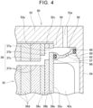
FIG. 4 is an enlarged cross-sectional view of a guide ring and a periphery thereof; -
FIG. 5 is an exploded perspective view of a stator core; -
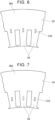
FIG. 6 is an enlarged plan view of amagnetic steel plate 36d; -
FIG. 7 is an enlarged plan view of amagnetic steel plate 36d of a motor according to a first modification; -
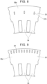
FIG. 8 is an enlarged plan view of amagnetic steel plate 36d of a motor according to a second modification; -
FIG. 9 is an enlarged plan view of amagnetic steel plate 36d of a motor according to a third modification; -
FIG. 10 is an enlarged plan view of amagnetic steel plate 36a of a motor according to a fourth modification; and -
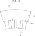
FIG. 11 is an enlarged plan view of amagnetic steel plate 36d of a motor according to a fifth modification. - An embodiment of the present disclosure will be described with reference to the drawings. Note that the embodiment described below is merely an example of a specific embodiment of the present disclosure and does not limit the present disclosure.
- A
motor 10 according to the embodiment illustrated inFIGS. 1 and2 has arotor 20, astator 30, and acase 50. Therotor 20 has ashaft 24. Thestator 30 has a cylindrical shape. Therotor 20 is disposed within a central hole of thestator 30 such that the central axis of theshaft 24 and the central axis of thestator 30 match. Therotor 20 and thestator 30 are housed in thecase 50. Hereinafter, a direction parallel to the rotation axis of the motor 10 (i.e., the central axis of the shaft 24) will be referred to as "axial direction", and a direction along a radius of a circle centered on the rotation axis of themotor 10 will be referred to as "radial direction". - The
case 50 has a cylindrical shape with a bottom, and has an outerperipheral wall 52 and apartition wall 54. The outerperipheral wall 52 has a tubular shape. Thepartition wall 54 is provided at one end portion of the outerperipheral wall 52 in the axial direction. Thepartition wall 54 is provided with a throughhole 54a at the center thereof. - The
stator 30 has astator core 32 and acoil 40. Note that inFIG. 2 , thecoil 40 is illustrated in a simplified manner. Thestator core 32 has a cylindrical shape. Thecoil 40 is wound around the stator core 32 (more specifically,teeth 34 described below). Thestator core 32 has anend face 32a, anend face 32b, and an outerperipheral face 32c. Theend face 32a is one end face of thestator core 32 in the axial direction, and theend face 32b is an end face that is opposite to theend face 32a. Acoil end 42a is provided on theend face 32a. Acoil end 42b is provided on theend face 32b. The coil ends 42a and 42b are bent portions of thecoil 40 wound around thestator core 32. Thecoil end 42a protrudes from theend face 32a, and thecoil end 42b protrudes from theend face 32b. As illustrated inFIG. 3 , thecoil end 42a is distributed in an annular shape on theend face 32a. In the same way, thecoil end 42b is distributed in an annular shape on theend face 32b. - As illustrated in
FIGS. 1 and2 , aninner face 52a of the outerperipheral wall 52 of thecase 50 has a cylindrical shape that extends along the outerperipheral face 32c of thestator core 32. Theinner face 52a of the outerperipheral wall 52 faces the outerperipheral face 32c of thestator core 32. Thepartition wall 54 of thecase 50 faces theend face 32a of thestator core 32. Thepartition wall 54 is an example of a facing portion. As illustrated inFIG. 2 , a gap is provided between thepartition wall 54 and theend face 32a of thestator core 32, and thecoil end 42a is disposed within this gap. As illustrated inFIG. 1 , a plurality of protrudingportions 38 is provided on the outerperipheral face 32c of thestator core 32. Also, a plurality of recessedportions 58 is provided on theinner face 52a of the outerperipheral wall 52. Thestator core 32 is housed in thecase 50 such that each protrudingportion 38 is disposed in a corresponding recessedportion 58. Each protrudingportion 38 is provided with a bolt fastening hole extending in the axial direction. Abolt 49 is inserted into each bolt fastening hole. Thestator core 32 is fastened to thecase 50 by thebolts 49. - The
rotor 20 is disposed within a center hole of thestator core 32 in a concentric state with thestator core 32. Theshaft 24 of therotor 20 is inserted into the throughhole 54a of thecase 50. Therotor 20 is rotatably supported within thecase 50 by bearings or the like. - As illustrated in
FIGS. 1 and2 , themotor 10 has aguide ring 60. Theguide ring 60 has a ring shape. As illustrated inFIG. 3 , an outer diameter of the guide ring 60 (i.e., the diameter at the largest diameter portion) is smaller than the diameter of the outerperipheral face 32c of thestator core 32. An inner diameter of the guide ring 60 (i.e., the diameter at the smallest diameter portion) is larger than an outer diameter of thecoil end 42a. As illustrated inFIGS. 1 and2 , theguide ring 60 is housed in thecase 50. Theguide ring 60 is disposed so as to extend annularly around the axis of the motor 10 (i.e., the shaft 24). Theguide ring 60 is disposed in a concentric state with therotor 20 and thestator core 32, between theend face 32a of thestator core 32 and thepartition wall 54 of thecase 50. Theguide ring 60 is interposed and fixed between theend face 32a and thepartition wall 54. Thecoil end 42a is disposed on an inner side in the radial direction from theguide ring 60. Theguide ring 60 divides space between thestator core 32 and thepartition wall 54 into an outerperipheral side space 56 and an innerperipheral side space 57. The outerperipheral side space 56 is a space surrounded by an inner face of thecase 50, an outer peripheral face of theguide ring 60, and theend face 32a, and has an annular shape. Hereinafter, the outerperipheral side space 56 will be referred to as "annularcoolant flow channel 56". - As illustrated in
FIG. 4 , one end portion of theguide ring 60 comes into contact with theend face 32a of thestator core 32. An O-ring 66 is provided at a connection portion between theguide ring 60 and theend face 32a. The O-ring 66 seals the connection portion between theguide ring 60 and theend face 32a. Note that other sealing members (e.g., a metal gasket, a liquid gasket, or the like) may be provided instead of the O-ring 66. Also, although theguide ring 60 is illustrated as being in contact with theend face 32a inFIG. 4 , a configuration may be made in which theguide ring 60 is connected to theend face 32a via a sealing member (i.e., without theguide ring 60 itself being in contact with theend face 32a). The other end portion of theguide ring 60 is in contact with thepartition wall 54. An O-ring 68 is provided at a connection portion between theguide ring 60 and thepartition wall 54. The O-ring 68 seals the connection portion between theguide ring 60 and thepartition wall 54. Note that other sealing members (e.g., a metal gasket, a liquid gasket, or the like) may be provided instead of the O-ring 68. Also, although theguide ring 60 is illustrated as being in contact with thepartition wall 54 inFIG. 4 , a configuration may be made in which theguide ring 60 is connected to thepartition wall 54 via a sealing member (i.e., without theguide ring 60 itself being in contact with the partition wall 54). - A stepped
portion 59 is provided on theinner face 52a of thecase 50. The steppedportion 59 is provided over the entirety thereof in a peripheral direction. Theend face 32a of thestator core 32 is in contact with the steppedportion 59 in the axial direction. The steppedportion 59 is an example of a contact portion. Theend face 32a is in close contact with the steppedportion 59. Note that a seal member (for example, an O-ring, a metal gasket, a liquid gasket, or the like) may be provided at an interface of theend face 32a and the steppedportion 59. - The
case 50 is provided with acoolant supply channel 53a. Thecoolant supply channel 53a connects outside of thecase 50 to the annularcoolant flow channel 56. As illustrated inFIG. 2 , acoolant ejection channel 53b is provided at a lower portion of thecase 50. Thecoolant ejection channel 53b connects inside and outside of thecase 50. Thecoolant ejection channel 53b is connected to thecoolant supply channel 53a via a circulation flow channel (omitted from illustration) provided outside thecase 50. The circulation flow channel is provided with a pump (omitted from illustration). When the pump is operated, the coolant is supplied from thecoolant supply channel 53a to the annularcoolant flow channel 56. The coolant supplied to the annularcoolant flow channel 56 flows inside of thecase 50 and is ejected from thecoolant ejection channel 53b to the circulation flow channel outside of thecase 50, which will be described later in detail. Thus, the coolant circulates through the circulation flow channel and thecase 50. In the present embodiment, the coolant is cooling oil. The cooling oil functions as a coolant that cools themotor 10, and also functions as a lubricating oil that lubricates therotor 20. - As illustrated in
FIG. 1 , theguide ring 60 is provided with a plurality ofcoolant discharge channels 62. As illustrated inFIG. 4 , eachcoolant discharge channel 62 passes through theguide ring 60 in the radial direction. As illustrated inFIG. 1 , theguide ring 60 is provided with thecoolant discharge channels 62 distributed in the peripheral direction. As illustrated inFIG. 4 , the annularcoolant flow channel 56 and the space 57 (i.e., the space in which thecoil end 42a is present) are connected by thecoolant discharge channels 62. Eachcoolant discharge channel 62 discharges the coolant in the annularcoolant flow channel 56 toward thecoil end 42a. -
FIG. 5 is an exploded view of thestator core 32. As illustrated inFIG. 5 , thestator core 32 is made up of a plurality of magnetic steel plates 36 stacked in the axial direction. Thestator core 32 has aback yoke 33 and a plurality of theteeth 34. Theback yoke 33 has a cylindrical shape. Eachtooth 34 protrudes from an inner peripheral face of theback yoke 33. That is to say, eachtooth 34 protrudes toward an inner side in the radial direction from theback yoke 33. Eachtooth 34 extends in the radial direction. Theteeth 34 are disposed at intervals in the peripheral direction. As described above, thecoil 40 is wound around theteeth 34. Eachtooth 34 is situated on the inner side in the radial direction from theguide ring 60. Accordingly, as illustrated inFIG. 3 , thecoil 40 is disposed on the inner side in the radial direction from theguide ring 60. - A
magnetic steel plate 36a illustrated inFIG. 5 is a magnetic steel plate situated on an end in the axial direction out of the magnetic steel plates 36. Themagnetic steel plate 36a makes up theend face 32a of thestator core 32. Amagnetic steel plate 36b is adjacent to themagnetic steel plate 36a, and amagnetic steel plate 36c is adjacent to themagnetic steel plate 36b. A plurality ofmagnetic steel plates 36d is stacked at a position adjacent to theelectromagnetic steel plate 36c. Themagnetic steel plates 36a to 36c are thinner than themagnetic steel plates 36d. Themagnetic steel plate 36a is provided with a plurality of throughholes 37a passing through themagnetic steel plate 36a in a thickness direction thereof. The throughholes 37a are provided distributed in the peripheral direction. As illustrated inFIG. 4 , the throughholes 37a are disposed on the outer side in the radial direction from theguide ring 60 and are connected to the annularcoolant flow channel 56. As illustrated inFIG. 5 , themagnetic steel plate 36b is provided with a plurality of throughholes 37b passing through themagnetic steel plate 36b in the thickness direction thereof. Each throughhole 37b is elongated in the radial direction. The throughholes 37b are provided distributed in the peripheral direction at the same intervals as the throughholes 37a. Themagnetic steel plate 36c is provided with a plurality of throughholes 37c passing through themagnetic steel plate 36c in the thickness direction. Each throughhole 37c is elongated in the radial direction. The throughholes 37c are provided distributed in the peripheral direction at the same intervals as the throughholes 37a. Eachelectromagnetic steel plate 36d is provided with a plurality of throughholes 37d passing through themagnetic steel plate 36d in the thickness direction. In eachmagnetic steel plate 36d, the throughholes 37d are provided distributed in the peripheral direction at the same intervals as the throughholes 37a. As illustrated inFIG. 4 , the throughholes 37d are disposed on the inner side in the radial direction from theguide ring 60. As illustrated inFIGS. 5 and6 , the throughholes 37d are provided at a boundary between theback yoke 33 and theteeth 34. That is to say, the throughholes 37d are provided spanning theback yoke 33 and theteeth 34. - As illustrated in
FIG. 4 , the throughholes 37a to 37d are linked to one another to form in-corecoolant flow channels 39 in thestator core 32. The throughholes 37a each make up a first flow channel (hereinafter referred to as "first flow channel 37a") that makes up an inlet situated on the outer side in the radial direction from the guide ring 60 (i.e., an inlet that opens to theend face 32a). The throughholes second flow channels guide ring 60 to a position on the inner side thereof in the radial direction. The throughholes 37d each make up a third flow channel (hereinafter referred to as "third flow channel 37d") that is situated on the inner side in the radial direction from theguide ring 60 and that also extends along the axial direction. Thefirst flow channel 37a and thethird flow channel 37d are connected by thesecond flow channels first flow channel 37a, thesecond flow channels third flow channel 37d form the in-corecoolant flow channel 39. A plurality of the in-corecoolant flow channels 39 is provided distributed in the peripheral direction inside thestator core 32. As illustrated inFIG. 2 , a downstream end of each in-corecoolant flow channel 39 opens at theend face 32b. - When the
motor 10 is operating, the coolant is supplied to the inside of thecase 50. The coolant is supplied from thecoolant supply channel 53a to the annularcoolant flow channel 56. The coolant in the annularcoolant flow channel 56 flows to thecoolant discharge channel 62 and the in-corecoolant flow channel 39. The coolant that flows into thecoolant discharge channel 62 is discharged toward thecoil end 42a. Thus, thecoil end 42a is cooled. The coolant discharged toward thecoil end 42a flows to the lower portion of thecase 50. Also, the coolant that has flowed into the in-corecoolant flow channel 39 flows through thethird flow channel 37d. Thethird flow channel 37d is provided within theteeth 34. Accordingly, thecoil 40 wound around theteeth 34 is efficiently cooled by the coolant flowing through thethird flow channel 37d. In particular, in the present embodiment, thethird flow channel 37d is provided on the boundary between theteeth 34 and theback yoke 33, and accordingly theteeth 34 and theback yoke 33 can be cooled effectively. The coolant that has flowed through thethird flow channel 37d to the downstream end thereof is discharged from theend face 32b. Thecoil end 42b is cooled by the coolant discharged from theend face 32b. The coolant discharged from theend face 32b flows to the lower portion of thecase 50. The coolant that has flowed to the lower portion of thecase 50 is sent from thecoolant ejection channel 53b to thecoolant supply channel 53a via the external pump. - As described above, the
motor 10 is cooled by the coolant flowing inside thecase 50. The in-corecoolant flow channel 39 extends from the inlet on the outer peripheral side of theguide ring 60 to thethird flow channel 37d on the inner peripheral side from theguide ring 60, and accordingly thecoil 40 wound around thestator core 32 on the inner peripheral side of theguide ring 60 can be efficiently cooled. - Also, in the
motor 10, theguide ring 60 is interposed between thecase 50 and thestator core 32 in the axial direction. According to this configuration, the connection portion between theguide ring 60 and thecase 50, and the connection portion between theguide ring 60 and thestator core 32, can be tightly connected, regardless of accuracy of form of theguide ring 60. Also, pressure can be applied to the connection portion between theguide ring 60 and thecase 50, and to the connection portion between theguide ring 60 and thestator core 32, simply by stacking thepartition wall 54 of thecase 50, theguide ring 60, and thestator core 32 in that order. This enables of these connection portions to be appropriately sealed. In particular, when sealing members are disposed at these connection portions, pressure is appropriately applied to the sealing members, and accordingly these connection portions can be appropriately sealed. This enables leakage of the coolant to be suppressed at the connection portions and flow rate of the coolant in each flow channel to be accurately controlled. Also, in themotor 10, thestator core 32 is in contact with the steppedportion 59 of thecase 50 in the axial direction. Accordingly, pressure can be appropriately applied to the connection portion between thestator core 32 and the steppedportion 59, and this connection portion can be appropriately sealed. Note that disposing a sealing member at the connection portion between thestator core 32 and the steppedportion 59 can further improve sealing performance of this connection portion. Improving the sealing performance of the connection portion between thestator core 32 and the steppedportion 59 enables leakage of the coolant at this connection portion to be suppressed, and the flow rate of the coolant in each flow channel can be controlled more accurately. Note that even if the coolant does flow to the outerperipheral face 32c of thestator core 32 via the connection portion between thestator core 32 and the steppedportion 59, this is not problematic in particular. Accordingly, when accurate control of the flow rate of the coolant in each flow channel is not all that important, low sealing performance of the connection portion between thestator core 32 and the steppedportion 59 is acceptable. - Also, in the
motor 10, the recessedportions 58 are present on theinner face 52a of thecase 50. The technology of connecting and sealing the outer peripheral face of the guide ring and the inner peripheral surface of the case, as disclosed inJP 2017-204980 guide ring 60 and thecase 50 are connected in the axial direction, and accordingly even when recessedportions 58 are present on theinner face 52a of thecase 50, the connection portion between theguide ring 60 and thecase 50 can be properly sealed. - Also, in the
motor 10, the inner diameter of theguide ring 60 is larger than the outer diameter of thecoil end 42a. Accordingly, theguide ring 60 can be attached to thestator core 32 after thestator 30 is completed by winding thecoil 40 around thestator core 32. That is to say, a process of winding thecoil 40 around thestator core 32 can be carried out in a state without theguide ring 60 being present. Accordingly, thestator 30 can be efficiently manufactured. - In the embodiment described above, the
third flow channel 37d is provided at the boundary between theteeth 34 and theback yoke 33. However, as illustrated inFIG. 7 , the entirethird flow channel 37d may be provided within theteeth 34. Also, as illustrated inFIG. 8 , the entirethird flow channel 37d may be provided inside theback yoke 33. Also, as illustrated inFIG. 9 , multiple in-corecoolant flow channels 39 may be provided densely on an outermost periphery portion of theback yoke 33. - Also, in the above-described embodiment, an inlet (i.e., through
hole 37a) is provided independently for each in-corecoolant flow channel 39, but as illustrated inFIG. 10 , a throughhole 37a may be provided so as to span multiple in-corecoolant flow channels 39. - Further, in
FIGS. 6 to 8 , one in-corecoolant flow channel 39 is provided for onetooth 34, but the number of in-corecoolant flow channels 39 may be fewer than the number ofteeth 34. For example, as illustrated inFIG. 11 , one in-corecoolant flow channel 39 may be provided for twoteeth 34. Reducing the number of in-corecoolant flow channels 39 in this way enables reduction in pressure loss in the coolant flow channels. - In the above-described embodiment, the
guide ring 60 is provided with thecoolant discharge channel 62. However, theguide ring 60 does not necessarily have to be provided with thecoolant discharge channel 62. In this case, improving sealing performance at the connection portion between theguide ring 60 and thepartition wall 54, and at the connection portion between theguide ring 60 and theend face 32a, enables the coolant to flow more efficiently over the annularcoolant flow channel 56. - Also, in the above-described embodiment, the
stator core 32 is fixed to thecase 50 by thebolts 49. However, thestator 30 may be fixed to thecase 50 by shrink fitting. In shrink fitting, thestator 30 is placed in thecase 50 in a state in which thecase 50 is heated, following which thecase 50 is cooled and caused to shrink. Theinner face 52a of thecase 50 thus is made to come into close contact with the outerperipheral face 32c of thestator core 32, and thestator 30 is fixed to thecase 50. In this case, the recessedportions 58 and the protrudingportions 38 can be eliminated from theinner face 52a of thecase 50 and the outerperipheral face 32c of thestator core 32. In this way, even when thestator 30 is fixed to thecase 50 by shrink fitting, the annularcoolant flow channel 56 can be easily formed by disposing theguide ring 60 so as to be interposed between thepartition wall 54 and theend face 32a. - In addition, in the above-described embodiment, the
partition wall 54 and the outerperipheral wall 52 are integral, but thepartition wall 54 may be configured as a separate body from the outerperipheral wall 52, and thepartition wall 54 may be fixed to the outerperipheral wall 52 by bolts or the like. - Also, in the above-described embodiment, the first flow channel is made up of one
magnetic steel plate 36a, but the first flow channel may be made up of a multiple magnetic steel plates that are stacked. Also, in the above-described embodiment, the second flow channel is made up of multiplemagnetic steel plates - Also, in the above-described embodiment, sealing members are provided at the connection portion between the
guide ring 60 and theend face 32a, and at the connection portion between theguide ring 60 and thepartition wall 54, but sealing members do not have to be provided. For example, forming theguide ring 60 from a highly flexible resin may enable high sealing performance to be realized without using a sealing member in some cases. Also, theguide ring 60 may be made of metal, in order to increase strength of theguide ring 60. Also, a structure may be made in which a groove is provided in thepartition wall 54, and theguide ring 60 is in contact with thepartition wall 54 within the groove. Also, inFIG. 4 , the diameter of theguide ring 60 increases the closer toward thepartition wall 54, but the diameter of theguide ring 60 may decrease the closer toward thepartition wall 54, or the diameter of theguide ring 60 may be constant regardless of the position in the axial direction. - Also, in the embodiment, the downstream portion of each in-core
coolant flow channel 39 extends linearly as illustrated inFIG. 2 , but the downstream portion may be shifted outward in the radial direction in a stepped manner, in the same way as at the upstream portion (i.e.,FIG. 4 ). This enables the coolant to be efficiently supplied to thecoil end 42b. - While embodiments are described in detail above, these embodiments are merely exemplary, and are not intended to limit the scope of the claims. The technology described in the claims includes various modifications and alterations of the specific examples described above. The technical elements described in the present specification or illustrated in the drawings exhibit technical utility solely or in various combinations, and are not limited to the combinations described in the claims as filed. Also, the technology exemplified in the present specification or in the drawings may simultaneously achieve a plurality of objects, and exhibit technical utility in itself by achieving one of the objects.
Claims (10)
- A motor (10), comprising:a stator core (32);a case (50) that houses the stator core (32), the case (50) including a facing portion (54) facing an end face (32a) of the stator core (32); anda guide ring (60) that is housed in the case (50), that includes a ring shape extending around a motor axis, and that is interposed between the end face (32a) and the facing portion (54), wherein:an annular coolant flow channel (56) is configured by a space surrounded by an inner face of the case (50), an outer peripheral face of the guide ring (60), and the end face (32a);a plurality of in-core coolant flow channels (39) is provided inside the stator core (32);an inlet of each of the in-core coolant flow channels (39) opens onto the end face (32a) at a position on an outer side in a radial direction from the guide ring (60); andthe inlet of each of the in-core coolant flow channels (39) is connected to the annular coolant flow channel (56).
- The motor according to claim 1, further comprising a coil (40) that is wound around the stator core (32) at a position on an inner side in the radial direction from the guide ring (60), wherein each of the in-core coolant flow channels (39) includesa first flow channel (37a) that is disposed on the outer side in the radial direction from the guide ring (60) and that is connected to the inlet,a second flow channel that extends from a position on the outer side in the radial direction from the guide ring (60) to a position on the inner side from the guide ring (60), and that is connected to the first flow channel, anda third flow channel (37d) that is disposed on the inner side in the radial direction from the guide ring (60), and that extends in an axial direction, and that is connected to the second flow channel.
- The motor according to claim 2, wherein the second flow channel extends in the radial direction.
- The motor according to claim 2 or 3, wherein:the stator core (32) is made up of a plurality of magnetic steel plates stacked in the axial direction;the magnetic steel plates include a first magnetic steel plate (36a), a second magnetic steel plate, and a third magnetic steel plate (36d);the first magnetic steel plate (36a) that is present in a range including the end face (32a), is provided with a first through hole (37a) that is disposed on the outer side in the radial direction from the guide ring (60);the second magnetic steel plate that is adjacent to the first magnetic steel plate (36a), is provided with a second through hole extending along the radial direction;a third through hole (37d) is provided in the third magnetic steel plate (36d) that is adjacent to the second magnetic steel plate, the third through hole (37d) is disposed on the inner side in the radial direction from the guide ring (60);the first through hole (37a) makes up the first flow channel (37a);the second through hole makes up the second flow channel; andthe third through hole (37d) makes up the third flow channel (37d).
- The motor according to claim 2 or 3, wherein:the stator core (32) includes a back yoke (33) and a plurality of teeth (34) protruding toward an inner side in the radial direction from the back yoke (33);the coil (40) is wound around the teeth (34); andthe third flow channel (37d) is provided inside a corresponding one of the teeth (34).
- The motor according to claim 5, wherein the third flow channel (37d) is provided at a boundary between the back yoke (33) and the corresponding one of the teeth (34).
- The motor according to any one of claims 1 to 3, wherein:the end face (32a) is provided with a coil end (42a); andan inner diameter of the guide ring (60) is larger than an outer diameter of the coil end (42a).
- The motor according to claim 2 or 3, wherein:a coil end (42a) is provided on the inner side in the radial direction from the guide ring (60); andthe guide ring (60) is provided with a coolant discharge channel (62) that passes through the guide ring (60) in the radial direction.
- The motor according to any one of claims 1 to 3, wherein:the case (50) includes a contact portion (59) that comes into contact with the end face (32a); anda seal member is provided at an interface of the end face (32a) and the contact portion (59).
- The motor according to any one of claims 1 to 3, wherein a recessed portion is provided on an inner peripheral face of the case (50).
Applications Claiming Priority (1)
| Application Number | Priority Date | Filing Date | Title |
|---|---|---|---|
| JP2023197375A JP2025083790A (en) | 2023-11-21 | 2023-11-21 | Motor |
Publications (1)
| Publication Number | Publication Date |
|---|---|
| EP4560888A1 true EP4560888A1 (en) | 2025-05-28 |
Family
ID=93430826
Family Applications (1)
| Application Number | Title | Priority Date | Filing Date |
|---|---|---|---|
| EP24210889.2A Pending EP4560888A1 (en) | 2023-11-21 | 2024-11-05 | Motor |
Country Status (5)
| Country | Link |
|---|---|
| US (1) | US20250167623A1 (en) |
| EP (1) | EP4560888A1 (en) |
| JP (1) | JP2025083790A (en) |
| KR (1) | KR20250075465A (en) |
| CN (1) | CN120033872A (en) |
Citations (4)
| Publication number | Priority date | Publication date | Assignee | Title |
|---|---|---|---|---|
| US20110181136A1 (en) * | 2010-01-28 | 2011-07-28 | Aisin Aw Co., Ltd. | Cooling structure of stator |
| DE102012022451B4 (en) * | 2012-11-09 | 2016-08-18 | Getrag Getriebe- Und Zahnradfabrik Hermann Hagenmeyer Gmbh & Cie Kg | Ring channel device, electric machine and drive train |
| JP2017204980A (en) | 2016-05-13 | 2017-11-16 | 本田技研工業株式会社 | Rotating electric machine and manufacturing method thereof |
| US20230017636A1 (en) * | 2021-07-14 | 2023-01-19 | Dana Automotive Systems Group, Llc | Systems for electric motor cooling |
Family Cites Families (5)
| Publication number | Priority date | Publication date | Assignee | Title |
|---|---|---|---|---|
| JPH09215270A (en) * | 1996-02-02 | 1997-08-15 | Honda Motor Co Ltd | Electric motor cooling structure |
| JP5699824B2 (en) * | 2010-07-26 | 2015-04-15 | 株式会社日本自動車部品総合研究所 | Electric motor |
| JP5497625B2 (en) * | 2010-12-28 | 2014-05-21 | トヨタ自動車株式会社 | Superconducting motor |
| JP2016220506A (en) * | 2015-05-26 | 2016-12-22 | 株式会社デンソー | Rotating electric machine |
| JP2023115653A (en) * | 2022-02-08 | 2023-08-21 | 本田技研工業株式会社 | stator core |
-
2023
- 2023-11-21 JP JP2023197375A patent/JP2025083790A/en active Pending
-
2024
- 2024-10-28 KR KR1020240148456A patent/KR20250075465A/en active Pending
- 2024-10-29 US US18/930,229 patent/US20250167623A1/en active Pending
- 2024-10-31 CN CN202411534888.7A patent/CN120033872A/en active Pending
- 2024-11-05 EP EP24210889.2A patent/EP4560888A1/en active Pending
Patent Citations (5)
| Publication number | Priority date | Publication date | Assignee | Title |
|---|---|---|---|---|
| US20110181136A1 (en) * | 2010-01-28 | 2011-07-28 | Aisin Aw Co., Ltd. | Cooling structure of stator |
| DE102012022451B4 (en) * | 2012-11-09 | 2016-08-18 | Getrag Getriebe- Und Zahnradfabrik Hermann Hagenmeyer Gmbh & Cie Kg | Ring channel device, electric machine and drive train |
| JP2017204980A (en) | 2016-05-13 | 2017-11-16 | 本田技研工業株式会社 | Rotating electric machine and manufacturing method thereof |
| JP6452166B2 (en) * | 2016-05-13 | 2019-01-16 | 本田技研工業株式会社 | Rotating electric machine and manufacturing method thereof |
| US20230017636A1 (en) * | 2021-07-14 | 2023-01-19 | Dana Automotive Systems Group, Llc | Systems for electric motor cooling |
Also Published As
| Publication number | Publication date |
|---|---|
| US20250167623A1 (en) | 2025-05-22 |
| JP2025083790A (en) | 2025-06-02 |
| CN120033872A (en) | 2025-05-23 |
| KR20250075465A (en) | 2025-05-28 |
Similar Documents
| Publication | Publication Date | Title |
|---|---|---|
| EP0566087B1 (en) | Pump casing made of sheet metal | |
| KR101440431B1 (en) | axial flux permanent magnet motor | |
| JP5718391B2 (en) | Rotating electric machine | |
| US6653758B2 (en) | Stator structure for rotary electric machine | |
| US11218050B2 (en) | Motor stator back-iron cooling through internal channels | |
| US12126242B2 (en) | Motor stator coolant distribution via internal channels | |
| JP2012518745A (en) | Integrated electric vane oil pump | |
| KR101097654B1 (en) | Radial rotary transfer assembly | |
| EP2455641B1 (en) | Mechanical sealing device | |
| EP4560888A1 (en) | Motor | |
| JP3979418B2 (en) | Motor generator cooling structure | |
| US12500483B2 (en) | Liquid cooling structure for motor | |
| US20190238009A1 (en) | Stator for rotary electric machine | |
| US20230344286A1 (en) | Stator of an electric machine and an electric machine | |
| KR20140119304A (en) | Axial flux permanent magnet motor | |
| JPWO2020017625A1 (en) | Motor and compressor with it | |
| US20250253723A1 (en) | Motor | |
| EP4601162A1 (en) | Motor | |
| KR20140118197A (en) | Bobin for stator core, stator assembly and axial flux permanent magnet motor | |
| KR20140118203A (en) | Magnet supporting unit and axial flux permanent magnet motor | |
| EP4216404A1 (en) | Dynamo-electric machine | |
| JP2025162277A (en) | Motor | |
| US11658524B2 (en) | Rotary electric machine | |
| US20240209890A1 (en) | Foil bearing | |
| EP4712319A2 (en) | Motor |
Legal Events
| Date | Code | Title | Description |
|---|---|---|---|
| PUAI | Public reference made under article 153(3) epc to a published international application that has entered the european phase |
Free format text: ORIGINAL CODE: 0009012 |
|
| STAA | Information on the status of an ep patent application or granted ep patent |
Free format text: STATUS: REQUEST FOR EXAMINATION WAS MADE |
|
| 17P | Request for examination filed |
Effective date: 20241121 |
|
| AK | Designated contracting states |
Kind code of ref document: A1 Designated state(s): AL AT BE BG CH CY CZ DE DK EE ES FI FR GB GR HR HU IE IS IT LI LT LU LV MC ME MK MT NL NO PL PT RO RS SE SI SK SM TR |
|
| RIN1 | Information on inventor provided before grant (corrected) |
Inventor name: ASAOKA, HIRONORI Inventor name: OHIRA, KENGO |