EP4560787A1 - Battery module and vehicle - Google Patents
Battery module and vehicle Download PDFInfo
- Publication number
- EP4560787A1 EP4560787A1 EP24213900.4A EP24213900A EP4560787A1 EP 4560787 A1 EP4560787 A1 EP 4560787A1 EP 24213900 A EP24213900 A EP 24213900A EP 4560787 A1 EP4560787 A1 EP 4560787A1
- Authority
- EP
- European Patent Office
- Prior art keywords
- csc
- mounting surface
- collection
- heat conductive
- assemblies
- Prior art date
- Legal status (The legal status is an assumption and is not a legal conclusion. Google has not performed a legal analysis and makes no representation as to the accuracy of the status listed.)
- Pending
Links
Images






Classifications
-
- H—ELECTRICITY
- H01—ELECTRIC ELEMENTS
- H01M—PROCESSES OR MEANS, e.g. BATTERIES, FOR THE DIRECT CONVERSION OF CHEMICAL ENERGY INTO ELECTRICAL ENERGY
- H01M50/00—Constructional details or processes of manufacture of the non-active parts of electrochemical cells other than fuel cells, e.g. hybrid cells
- H01M50/20—Mountings; Secondary casings or frames; Racks, modules or packs; Suspension devices; Shock absorbers; Transport or carrying devices; Holders
- H01M50/262—Mountings; Secondary casings or frames; Racks, modules or packs; Suspension devices; Shock absorbers; Transport or carrying devices; Holders with fastening means, e.g. locks
-
- H—ELECTRICITY
- H01—ELECTRIC ELEMENTS
- H01M—PROCESSES OR MEANS, e.g. BATTERIES, FOR THE DIRECT CONVERSION OF CHEMICAL ENERGY INTO ELECTRICAL ENERGY
- H01M50/00—Constructional details or processes of manufacture of the non-active parts of electrochemical cells other than fuel cells, e.g. hybrid cells
- H01M50/20—Mountings; Secondary casings or frames; Racks, modules or packs; Suspension devices; Shock absorbers; Transport or carrying devices; Holders
- H01M50/284—Mountings; Secondary casings or frames; Racks, modules or packs; Suspension devices; Shock absorbers; Transport or carrying devices; Holders with incorporated circuit boards, e.g. printed circuit boards [PCB]
- H01M50/287—Fixing of circuit boards to lids or covers
-
- B—PERFORMING OPERATIONS; TRANSPORTING
- B60—VEHICLES IN GENERAL
- B60R—VEHICLES, VEHICLE FITTINGS, OR VEHICLE PARTS, NOT OTHERWISE PROVIDED FOR
- B60R16/00—Electric or fluid circuits specially adapted for vehicles and not otherwise provided for; Arrangement of elements of electric or fluid circuits specially adapted for vehicles and not otherwise provided for
- B60R16/02—Electric or fluid circuits specially adapted for vehicles and not otherwise provided for; Arrangement of elements of electric or fluid circuits specially adapted for vehicles and not otherwise provided for electric constitutive elements
- B60R16/03—Electric or fluid circuits specially adapted for vehicles and not otherwise provided for; Arrangement of elements of electric or fluid circuits specially adapted for vehicles and not otherwise provided for electric constitutive elements for supply of electrical power to vehicle subsystems or for
- B60R16/033—Electric or fluid circuits specially adapted for vehicles and not otherwise provided for; Arrangement of elements of electric or fluid circuits specially adapted for vehicles and not otherwise provided for electric constitutive elements for supply of electrical power to vehicle subsystems or for characterised by the use of electrical cells or batteries
-
- H—ELECTRICITY
- H01—ELECTRIC ELEMENTS
- H01M—PROCESSES OR MEANS, e.g. BATTERIES, FOR THE DIRECT CONVERSION OF CHEMICAL ENERGY INTO ELECTRICAL ENERGY
- H01M10/00—Secondary cells; Manufacture thereof
- H01M10/60—Heating or cooling; Temperature control
- H01M10/61—Types of temperature control
- H01M10/613—Cooling or keeping cold
-
- H—ELECTRICITY
- H01—ELECTRIC ELEMENTS
- H01M—PROCESSES OR MEANS, e.g. BATTERIES, FOR THE DIRECT CONVERSION OF CHEMICAL ENERGY INTO ELECTRICAL ENERGY
- H01M10/00—Secondary cells; Manufacture thereof
- H01M10/60—Heating or cooling; Temperature control
- H01M10/62—Heating or cooling; Temperature control specially adapted for specific applications
- H01M10/625—Vehicles
-
- H—ELECTRICITY
- H01—ELECTRIC ELEMENTS
- H01M—PROCESSES OR MEANS, e.g. BATTERIES, FOR THE DIRECT CONVERSION OF CHEMICAL ENERGY INTO ELECTRICAL ENERGY
- H01M10/00—Secondary cells; Manufacture thereof
- H01M10/60—Heating or cooling; Temperature control
- H01M10/64—Heating or cooling; Temperature control characterised by the shape of the cells
- H01M10/643—Cylindrical cells
-
- H—ELECTRICITY
- H01—ELECTRIC ELEMENTS
- H01M—PROCESSES OR MEANS, e.g. BATTERIES, FOR THE DIRECT CONVERSION OF CHEMICAL ENERGY INTO ELECTRICAL ENERGY
- H01M10/00—Secondary cells; Manufacture thereof
- H01M10/60—Heating or cooling; Temperature control
- H01M10/65—Means for temperature control structurally associated with the cells
- H01M10/655—Solid structures for heat exchange or heat conduction
- H01M10/6554—Rods or plates
- H01M10/6555—Rods or plates arranged between the cells
-
- H—ELECTRICITY
- H01—ELECTRIC ELEMENTS
- H01M—PROCESSES OR MEANS, e.g. BATTERIES, FOR THE DIRECT CONVERSION OF CHEMICAL ENERGY INTO ELECTRICAL ENERGY
- H01M10/00—Secondary cells; Manufacture thereof
- H01M10/60—Heating or cooling; Temperature control
- H01M10/65—Means for temperature control structurally associated with the cells
- H01M10/655—Solid structures for heat exchange or heat conduction
- H01M10/6556—Solid parts with flow channel passages or pipes for heat exchange
-
- H—ELECTRICITY
- H01—ELECTRIC ELEMENTS
- H01M—PROCESSES OR MEANS, e.g. BATTERIES, FOR THE DIRECT CONVERSION OF CHEMICAL ENERGY INTO ELECTRICAL ENERGY
- H01M10/00—Secondary cells; Manufacture thereof
- H01M10/60—Heating or cooling; Temperature control
- H01M10/65—Means for temperature control structurally associated with the cells
- H01M10/655—Solid structures for heat exchange or heat conduction
- H01M10/6556—Solid parts with flow channel passages or pipes for heat exchange
- H01M10/6557—Solid parts with flow channel passages or pipes for heat exchange arranged between the cells
-
- H—ELECTRICITY
- H01—ELECTRIC ELEMENTS
- H01M—PROCESSES OR MEANS, e.g. BATTERIES, FOR THE DIRECT CONVERSION OF CHEMICAL ENERGY INTO ELECTRICAL ENERGY
- H01M10/00—Secondary cells; Manufacture thereof
- H01M10/60—Heating or cooling; Temperature control
- H01M10/65—Means for temperature control structurally associated with the cells
- H01M10/656—Means for temperature control structurally associated with the cells characterised by the type of heat-exchange fluid
- H01M10/6567—Liquids
-
- H—ELECTRICITY
- H01—ELECTRIC ELEMENTS
- H01M—PROCESSES OR MEANS, e.g. BATTERIES, FOR THE DIRECT CONVERSION OF CHEMICAL ENERGY INTO ELECTRICAL ENERGY
- H01M50/00—Constructional details or processes of manufacture of the non-active parts of electrochemical cells other than fuel cells, e.g. hybrid cells
- H01M50/20—Mountings; Secondary casings or frames; Racks, modules or packs; Suspension devices; Shock absorbers; Transport or carrying devices; Holders
- H01M50/204—Racks, modules or packs for multiple batteries or multiple cells
- H01M50/207—Racks, modules or packs for multiple batteries or multiple cells characterised by their shape
- H01M50/213—Racks, modules or packs for multiple batteries or multiple cells characterised by their shape adapted for cells having curved cross-section, e.g. round or elliptic
-
- H—ELECTRICITY
- H01—ELECTRIC ELEMENTS
- H01M—PROCESSES OR MEANS, e.g. BATTERIES, FOR THE DIRECT CONVERSION OF CHEMICAL ENERGY INTO ELECTRICAL ENERGY
- H01M50/00—Constructional details or processes of manufacture of the non-active parts of electrochemical cells other than fuel cells, e.g. hybrid cells
- H01M50/50—Current conducting connections for cells or batteries
- H01M50/502—Interconnectors for connecting terminals of adjacent batteries; Interconnectors for connecting cells outside a battery casing
- H01M50/507—Interconnectors for connecting terminals of adjacent batteries; Interconnectors for connecting cells outside a battery casing comprising an arrangement of two or more busbars within a container structure, e.g. busbar modules
-
- H—ELECTRICITY
- H01—ELECTRIC ELEMENTS
- H01M—PROCESSES OR MEANS, e.g. BATTERIES, FOR THE DIRECT CONVERSION OF CHEMICAL ENERGY INTO ELECTRICAL ENERGY
- H01M50/00—Constructional details or processes of manufacture of the non-active parts of electrochemical cells other than fuel cells, e.g. hybrid cells
- H01M50/50—Current conducting connections for cells or batteries
- H01M50/502—Interconnectors for connecting terminals of adjacent batteries; Interconnectors for connecting cells outside a battery casing
- H01M50/519—Interconnectors for connecting terminals of adjacent batteries; Interconnectors for connecting cells outside a battery casing comprising printed circuit boards [PCB]
-
- H—ELECTRICITY
- H01—ELECTRIC ELEMENTS
- H01M—PROCESSES OR MEANS, e.g. BATTERIES, FOR THE DIRECT CONVERSION OF CHEMICAL ENERGY INTO ELECTRICAL ENERGY
- H01M10/00—Secondary cells; Manufacture thereof
- H01M10/42—Methods or arrangements for servicing or maintenance of secondary cells or secondary half-cells
- H01M10/425—Structural combination with electronic components, e.g. electronic circuits integrated to the outside of the casing
- H01M2010/4271—Battery management systems including electronic circuits, e.g. control of current or voltage to keep battery in healthy state, cell balancing
-
- H—ELECTRICITY
- H01—ELECTRIC ELEMENTS
- H01M—PROCESSES OR MEANS, e.g. BATTERIES, FOR THE DIRECT CONVERSION OF CHEMICAL ENERGY INTO ELECTRICAL ENERGY
- H01M2220/00—Batteries for particular applications
- H01M2220/20—Batteries in motive systems, e.g. vehicle, ship, plane
-
- Y—GENERAL TAGGING OF NEW TECHNOLOGICAL DEVELOPMENTS; GENERAL TAGGING OF CROSS-SECTIONAL TECHNOLOGIES SPANNING OVER SEVERAL SECTIONS OF THE IPC; TECHNICAL SUBJECTS COVERED BY FORMER USPC CROSS-REFERENCE ART COLLECTIONS [XRACs] AND DIGESTS
- Y02—TECHNOLOGIES OR APPLICATIONS FOR MITIGATION OR ADAPTATION AGAINST CLIMATE CHANGE
- Y02E—REDUCTION OF GREENHOUSE GAS [GHG] EMISSIONS, RELATED TO ENERGY GENERATION, TRANSMISSION OR DISTRIBUTION
- Y02E60/00—Enabling technologies; Technologies with a potential or indirect contribution to GHG emissions mitigation
- Y02E60/10—Energy storage using batteries
Definitions
- the present disclosure relates to the field of battery technologies, particularly to a battery module and a vehicle.
- CCS cells contact system
- CSC cell supervision circuit
- the intermediate wiring harnesses include many wires and require complicated assembly. Besides, wire connection positions of the intermediate wiring harness are prone to poor contact, which in turn leads to abnormal collection and poor practicality of a battery management unit (BMU).
- BMU battery management unit
- the present disclosure provides a battery module.
- the battery module includes: a box, a battery pack, one or more CCS assemblies, and one or more collection modules.
- the battery pack is installed in the box and comprising multiple battery cells.
- the CCS assemblies include one or more collection lines electrically connected to the plurality of battery cells and a connection circuit board.
- Each CCS assembly includes one of the one or more collection lines and the connection circuit board is connected to one end of the collection line.
- Each collection module includes one of the one or more mounting bracket and one or more of the one or more CSC assemblies.
- the mounting bracket of each collection module is installed in the box and is opposite to the battery pack.
- the one or more CSC assemblies of each collection module are disposed on a side of the mounting bracket of the collection module and directly electrically connected to the connection circuit board.
- the present disclosure further provides a vehicle.
- the vehicle includes a battery module.
- the battery module includes: a box, a battery pack, one or more CCS assemblies, and one or more collection modules.
- the battery pack is installed in the box and comprising multiple battery cells.
- the CCS assemblies include one or more collection lines electrically connected to the plurality of battery cells and a connection circuit board.
- Each CCS assembly includes one of the one or more collection lines and the connection circuit board is connected to one end of the collection line.
- Each collection module includes one of the one or more mounting bracket and one or more of the one or more CSC assemblies.
- the mounting bracket of each collection module is installed in the box and is opposite to the battery pack.
- the one or more CSC assemblies of each collection module are disposed on a side of the mounting bracket of the collection module and directly electrically connected to the connection circuit board.
- the mounting bracket is arranged to be opposite to the battery cells, to arrange the mounting bracket close to the CCS assembly, which facilitates direct connection between the connection circuit board and the CSC assembly mounted on the mounting bracket and eliminates the need for any intermediate wiring harness between the connection circuit board and the CSC assembly, thereby reducing unnecessary materials, improving assembly efficiency, and reducing costs.
- 1-CCS assembly 11-collection line; 12-connection circuit board; 13-connection bar; 2-mounting bracket; 21-first mounting surface; 211-first fixing protrusion; 22-second mounting surface; 221-second fixing protrusion; 23-fixing lug; 24-mounting lug; 241-slit; 3-first CSC assembly; 30-collection plate; 31-first collection plate; 32-first connector; 321-first connection socket; 4-second CSC assembly; 41-second collection plate; 42-second connector; 421-second connection socket; 60-first heat conductive structure; 5-second heat conductive sheet; 6-first heat conductive sheet; 61-first section; 62-second section; 63-third section; 70-second heat conductive structure; 7-heat conductive foam; 8-buckle; 9-battery cell support; 10-liquid cooling plate; 101-connection structure; 102-electrically insulating board; 103-battery cell; 104-battery pack; 105-battery cell row; 106-collection module; 1000-battery module
- connection may be a fixed connection, a detachable connection, or an integral connection; may be a mechanical connection or an electrical connection; or may be a direct connection, an indirect connection through an intermediate medium, internal communication between two elements, or an interaction relationship between two elements.
- connection may be a fixed connection, a detachable connection, or an integral connection; may be a mechanical connection or an electrical connection; or may be a direct connection, an indirect connection through an intermediate medium, internal communication between two elements, or an interaction relationship between two elements.
- a first feature being “above” or “below” a second feature includes the first feature directly contacting the second feature and the first feature contacting the second feature through an additional feature therebetween.
- the first feature being “on”, “above”, and “on top of” the second feature includes the first feature being directly above and diagonally above the second feature, and a horizontal level of the first feature being higher than a horizontal level of the second feature.
- the first feature being “under”, “below”, and “beneath” the second feature includes the first feature being directly below and diagonally below the second feature, and a horizontal level of the first feature being lower than a horizontal level of the second feature.
- FIGS. 8-12 illustrate a battery module 1000 according to some embodiments of the present disclosure.
- the battery module 1000 includes a box and a main body 1200 installed in the box.
- the box includes a top cover 1100 and a bottom cover 1300.
- the top cover 110, the main body 1200, and the bottom cover 1300 may be connected by means such as bolt connection, snap connection, etc., such that the main body 1200 of the battery module may be accommodated in the box.
- the main body 1200 of the battery module provided by some embodiments of the present disclosure includes: a battery pack 104, a cells contact system (CCS) assembly 1, and a collection module 106.
- a battery pack 104 a cells contact system (CCS) assembly 1
- CCS cells contact system
- the battery pack 104 is installed in the box and includes a plurality of battery cells 103.
- the CCS assembly 1 includes a collection line 11 configured to be electrically connected to the plurality of battery cells 103 and a connection circuit board 12 connected to one end of the connection line 11.
- a battery module provided by some embodiments of the present disclosure includes a box, a battery pack 104, a plurality of CCS assemblies 1, and a collection module 106.
- the battery pack 104 is disposed in the box and includes multiple battery cells 103.
- the battery cells 103 may be cylindrical batteries or prismatic batteries. The following embodiments will be described using cylindrical batteries as an example.
- the collection module 106 includes a mounting bracket 2 and a plurality of cell supervision circuit (CSC) assemblies.
- the mounting bracket 2 is installed in the box and is opposite to the battery pack 104.
- the CSC assemblies are each located on a side of the mounting bracket 2 and directly electrically connected to a corresponding connection circuit board 12.
- the plurality of CSC assemblies include one or more first CSC assemblies 3 and one or more second CSC assemblies 4.
- Each first CSC assembly 3 is disposed on a first mounting surface 21 of the mounting bracket 2, and each second CSC assembly 4 is disposed on a second mounting surface 22 of the mounting bracket 2.
- two first CSC assemblies 3 are provided on the first mounting surface 21, and one second CSC assembly 4 is located between the two first CSC assemblies 3, and the second CSC assembly 4 and the two first CSC assemblies 3 are in a staggered arrangement.
- a utilization ratio of mounting space of the mounting bracket 2 may be improved and a volume of the battery module may be reduced.
- the staggered arrangement of the CSC assemblies on the first mounting surface 21 and the second mounting surface 22 helps reduce thermal impact between the CSC assemblies and improve heat dissipation efficiency.
- each CSC assembly may include a collection plate 30 and a connector provided on one side of the first collection plate 30, and the connector is electrically connected to a corresponding connection circuit board 12.
- each first CSC assembly 3 includes a first collection plate 31 and a first connector 32 provided on a side of the first collection plate 31.
- the second CSC assembly 4 includes a second collection plate 41 and a second connector 42 provided on a side of the second collection plate 41.
- the first mounting surface 21 is provided with a plurality of first fixing protrusions 211
- the second mounting surface 22 is provided with a plurality of second fixing protrusions 221.
- the first collecting plates 31 are each bolted to corresponding one or more of the plurality of first fixing protrusions 211 and maintain a distance from the first mounting surface 21.
- the second collection plate 41 is bolted to corresponding one or more of the plurality of second fixing protrusions 221 and maintains a distance from the second mounting surface 22.
- each of the first connectors 32 and the second connector 42 is electrically connected to the connection circuit board 12 of a corresponding CCS assembly 1.
- the first connectors 32 are each located between the corresponding first collection plate 31 and the first mounting surface 21, and the second collection plate 41 is located between the second connector 42 and the second mounting surface 22, to maximize mounting space on the mounting bracket 2 and facilitate the electrical connection between each of the first connectors 32 and the second connector 42 and the corresponding connection circuit board 12.
- each first connector 32 is provided with a first connection socket 321 opening toward the corresponding CCS assembly 1
- the second connector 42 is provided with a second connection socket 421 opening toward the corresponding CCS assembly 1.
- the connection circuit board 12 of the CCS assembly 1 corresponding to a first connector 32 is inserted into the first connector 32.
- the connection circuit board 12 of the CCS assembly 1 corresponding to a second connector 42 is inserted into the second connector 42.
- the collection lines 11 herein do not need to be bent too many times, thereby reducing damage to the collection lines 11.
- the second mounting surface 22 is provided with two fixing lugs 23 and two mounting lugs 24.
- the two mounting lugs 24 are located between the two mounting lugs 23.
- a surface of any one of the mounting lugs 24 facing the other mounting lug 24 is provided with a slit 241, and the slit 241 extends through the mounting lug 24 in a direction away from the second mounting surface 22.
- the second CSC assembly 4 further includes a heat conductive member including a first heat conductive structure 60.
- the first heat conductive structure 60 includes a first heat conductive sheet 6 and a second heat conductive sheet 5.
- the first heat conductive sheet 6 includes a second section 62 and a first section 61 and a third section 63 that are respectively connected to two ends of the second section 62.
- the first section 61 is arranged opposite to the second mounting surface 22.
- the third section 63 is arranged at an angle with the second mounting surface 22. A middle portion of the third section 63 is connected to one end of the second section 62, and two ends of the third section 63 are disposed in the two slits 241 respectively.
- the first heat conductive sheet 6 is located between the two mounting lugs 24 and interference-fit with the two mounting lugs 24 and the mounting bracket 2.
- the second heat conductive sheet 5 is connected in a heat conductive manner between the third section 63 and a bottom of the box.
- the bottom of the box may be a crossbeam (i.e., a crossbeam 1310 of the bottom cover 1300) at the bottom of the box.
- the heat on the second collection plate 41 is transferred to the box through the first heat conductive sheet 6 and the second heat conductive sheet 5.
- the reason for splitting the first heat conductive structure into the first heat conductive sheet 6 and the second heat conductive sheet 5 is that a limited volume of each mounting lug 24 makes it inconvenient to provide a larger slit 241 for both the third section 63 of the first heat conductive sheet 6 and the second heat conductive sheet 5 to snap in. Thus, only the third section 63 of the first heat conductive sheet 6 is disposed into the slit 24. Furthermore, a thickness of the second heat conductive sheet 5 may be adjusted according to a distance between the third section 63 and the bottom of the box for a smooth transfer of heat.
- the heat conductive member further includes a plurality of second heat conductive structures 70.
- three second heat conductive structures 70 are provided, where two of the three second heat conductive structures 70 are respectively corresponding to the two first CSC assemblies 3, and each of the two second heat conductive structures 70 is provided between a surface of the first collection plate 31 of a corresponding first CSC assembly 3 away from the first mounting surface 21 and a side wall (for example, an inner wall of a left side of the bottom cover 1300, referring to FIG. 8 and FIG. 10 ) of the box; and one of the three second heat conductive structure 70 is connected in a heat conductive manner between the first section 61 of the first heat conductive sheet 6 and the second collection plate 41.
- the material of the second heat conductive structures 70 is heat conductive foam 7 which plays the role of heat conduction on the one hand, and the role of buffering external impact on the other hand.
- the two fixing lugs 23 are bolted to the crossbeam 1310 (as shown in FIG. 8 ) of the box.
- the first mounting surface 21 of the mounting bracket 2 is further provided with buckles 8.
- the buckles 8 are snapped into a slot 1320 (as shown in FIG. 8 ) of the box.
- the two connection ways are used to realize fixed installation of the mounting bracket 2.
- the mounting bracket 2, the two fixing lugs 23, and the two mounting lugs 24 are integrally formed.
- the third section 63 and the second mounting surface 22 form an included angle of 90°, and the first heat conductive sheet 6 and the second heat conductive sheet 5 are made of a same metal material.
- Some embodiments of the present disclosure further provide a vehicle, including a battery module and a battery management system (BMS).
- the BMS is configured to be electrically connected to the one or more CSC assemblies to collect information of each cell and detect voltage and temperature of each cell.
- the battery module includes a box, a battery pack 104, a plurality of CCS assemblies 1, and a plurality of collection modules 106.
- the battery pack 104 includes a plurality of battery cell rows 105.
- the battery cell rows 105 are spaced apart along a width direction of a connection structure 101.
- Each battery cell row 105 includes a plurality of battery cells 103.
- the plurality of battery cells 103 are spaced apart along a length direction of the connection structure 101.
- the battery module further includes a battery cell support 9, a plurality of liquid cooling plates 10, a connection structure 101, and an electrically insulating board 102.
- the plurality of battery cells 103 are arranged on the battery cell support 9.
- the battery cell support 9 is made of an electrically insulating material and plays the role of electrical insulation between the battery cells 103 and the box.
- the battery cell support 9 is provided with a plurality of openings each corresponding to one of the plurality of battery cells 103. The openings are configured as pressure relief valves to expose the battery cells 103.
- Two of the liquid cooling plates 10 are disposed on two sides of the battery pack 104 to cool the outermost battery cells 103 thereof. Other liquid cooling plates 10 are respectively disposed between the plurality of battery cells 103 to cool down the battery cells 103.
- Each CCS assembly 1 further includes a plurality of connection bars 13 each electrically connected to a corresponding collection line 11.
- the connection bars 13 connect adjacent battery cells 103 in series.
- the electrically insulating board 102 and the plurality of connection bars 13 are provided with exhaust holes, and the exhaust holes are configured for the foam overflow and gas exhaust during a foaming process of the foam sealing agent.
- the module is hoisted to put into the box, the collection modules 106 are installed in the box, and the connectors on the CCS assemblies 1 are respectively plugged into the connection circuit boards 12 of the corresponding collection modules 106, so that voltages and temperature signals of the battery cells 103 may be collected.
Landscapes
- Chemical & Material Sciences (AREA)
- Chemical Kinetics & Catalysis (AREA)
- Electrochemistry (AREA)
- General Chemical & Material Sciences (AREA)
- Engineering & Computer Science (AREA)
- Manufacturing & Machinery (AREA)
- Mechanical Engineering (AREA)
- Battery Mounting, Suspending (AREA)
- Secondary Cells (AREA)
Abstract
A battery module includes a box (1100, 1300), a battery pack (104), CCS assemblies (1), and collection assemblies (106). The battery pack (104) is installed in the box (1100, 1300) and includes battery cells (103). Each CCS assembly (1) includes one collection line (11) electrically connected to some battery cells (103) and one connection circuit board (12) connected to one end of the collection line (11). The collection modules (106) include mounting brackets (2) and CSC assemblies (3, 4) in a one-to-one correspondence with the connection circuit boards (12). The mounting bracket (2) of each collection module (106) is installed in the box (1100, 1300) and is opposite to the battery pack (104). The CSC assemblies (3, 4) of each collection module (106) are disposed on a side of the mounting bracket (2) of the collection module (106) and directly electrically connected to corresponding one or more connection circuit boards (12).
Description
- The present disclosure relates to the field of battery technologies, particularly to a battery module and a vehicle.
- Most of battery systems adopt such an assembly method in which multiple modules are connected in series and mounted on a tray. After collecting voltages and temperature signals of the modules, a cells contact system (CCS) assembly communicates with a cell supervision circuit (CSC) assembly through intermediate wiring harnesses.
- In related technology, the intermediate wiring harnesses include many wires and require complicated assembly. Besides, wire connection positions of the intermediate wiring harness are prone to poor contact, which in turn leads to abnormal collection and poor practicality of a battery management unit (BMU).
- In an aspect, the present disclosure provides a battery module. The battery module includes: a box, a battery pack, one or more CCS assemblies, and one or more collection modules. The battery pack is installed in the box and comprising multiple battery cells. The CCS assemblies include one or more collection lines electrically connected to the plurality of battery cells and a connection circuit board. Each CCS assembly includes one of the one or more collection lines and the connection circuit board is connected to one end of the collection line. Each collection module includes one of the one or more mounting bracket and one or more of the one or more CSC assemblies. The mounting bracket of each collection module is installed in the box and is opposite to the battery pack. The one or more CSC assemblies of each collection module are disposed on a side of the mounting bracket of the collection module and directly electrically connected to the connection circuit board.
- In another aspect, the present disclosure further provides a vehicle. The vehicle includes a battery module. The battery module includes: a box, a battery pack, one or more CCS assemblies, and one or more collection modules. The battery pack is installed in the box and comprising multiple battery cells. The CCS assemblies include one or more collection lines electrically connected to the plurality of battery cells and a connection circuit board. Each CCS assembly includes one of the one or more collection lines and the connection circuit board is connected to one end of the collection line. Each collection module includes one of the one or more mounting bracket and one or more of the one or more CSC assemblies. The mounting bracket of each collection module is installed in the box and is opposite to the battery pack. The one or more CSC assemblies of each collection module are disposed on a side of the mounting bracket of the collection module and directly electrically connected to the connection circuit board.
- In the battery module provided by some embodiments of the present disclosure, the mounting bracket is arranged to be opposite to the battery cells, to arrange the mounting bracket close to the CCS assembly, which facilitates direct connection between the connection circuit board and the CSC assembly mounted on the mounting bracket and eliminates the need for any intermediate wiring harness between the connection circuit board and the CSC assembly, thereby reducing unnecessary materials, improving assembly efficiency, and reducing costs.
-
-
FIG. 1 is a schematic diagram of a main body of a battery module according to some embodiments of the present disclosure. -
FIG. 2 is an exploded view of the main body of the battery module according to some embodiments of the present disclosure. -
FIG. 3 is a schematic diagram of cell supervision circuit (CSC) assemblies and cells contact system (CCS) assemblies according to some embodiments of the present disclosure. -
FIG. 4 is a schematic diagram showing part of the CSC assemblies and CCS assemblies according to some embodiments of the present disclosure. -
FIG. 5 is an enlarged view of the region A inFIG. 4 . -
FIG. 6 is a schematic diagram of the CSC assembly according to some embodiments of the present disclosure. -
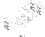
FIG. 7 is an exploded view of the CSC assembly according to some embodiments of the present disclosure. -
FIG. 8 is an exploded view of a battery module according to some embodiments of the present disclosure. -
FIG. 9 is a front view of the exploded view of the battery module shown inFIG. 8 . -
FIG. 10 is a left view of the exploded view of the battery module shown inFIG. 8 . -
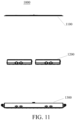
FIG. 11 is a right view of the exploded view of the battery module shown inFIG. 8 . -
FIG. 12 is a top view of the exploded view of the battery module shown inFIG. 8 . -
FIG. 13 is a bottom view of the exploded view of the battery module shown inFIG. 8 . - 1-CCS assembly; 11-collection line; 12-connection circuit board; 13-connection bar; 2-mounting bracket; 21-first mounting surface; 211-first fixing protrusion; 22-second mounting surface; 221-second fixing protrusion; 23-fixing lug; 24-mounting lug; 241-slit; 3-first CSC assembly; 30-collection plate; 31-first collection plate; 32-first connector; 321-first connection socket; 4-second CSC assembly; 41-second collection plate; 42-second connector; 421-second connection socket; 60-first heat conductive structure; 5-second heat conductive sheet; 6-first heat conductive sheet; 61-first section; 62-second section; 63-third section; 70-second heat conductive structure; 7-heat conductive foam; 8-buckle; 9-battery cell support; 10-liquid cooling plate; 101-connection structure; 102-electrically insulating board; 103-battery cell; 104-battery pack; 105-battery cell row; 106-collection module; 1000-battery module; 1100-top cover; 1200-bottom cover; 1310-crossbeam of the bottom cover; and 1320-slot.
- In the description of the present disclosure, it should be noted that unless otherwise explicitly specified and limited terms "interconnect", "connect", and "fix" should be understood in a broad sense. For example, a connection may be a fixed connection, a detachable connection, or an integral connection; may be a mechanical connection or an electrical connection; or may be a direct connection, an indirect connection through an intermediate medium, internal communication between two elements, or an interaction relationship between two elements. A person of ordinary skill in the art can understand specific meanings of the terms in the present disclosure according to specific situations.
- In the present disclosure, unless otherwise explicitly stated and limited, a first feature being "above" or "below" a second feature includes the first feature directly contacting the second feature and the first feature contacting the second feature through an additional feature therebetween. Furthermore, the first feature being "on", "above", and "on top of" the second feature includes the first feature being directly above and diagonally above the second feature, and a horizontal level of the first feature being higher than a horizontal level of the second feature. The first feature being "under", "below", and "beneath" the second feature includes the first feature being directly below and diagonally below the second feature, and a horizontal level of the first feature being lower than a horizontal level of the second feature.
- In the description of the present disclosure, it should be noted that terms "up", "down", "right", etc., indicate orientations or position relationships based on the accompanying drawings, which is only for the convenience of description and simplifying operations, and does not indicate or imply that indicated devices or elements should have particular orientations or be constructed and operated in particular orientations, and cannot be construed as a limitation on the present disclosure. In addition, terms "first" and "second" are only used to differentiate in description and have no special meaning.
-
FIGS. 8-12 illustrate abattery module 1000 according to some embodiments of the present disclosure. As shown inFigures 8-13 , thebattery module 1000 includes a box and amain body 1200 installed in the box. The box includes atop cover 1100 and abottom cover 1300. In some embodiments, the top cover 110, themain body 1200, and thebottom cover 1300 may be connected by means such as bolt connection, snap connection, etc., such that themain body 1200 of the battery module may be accommodated in the box. - Referring to
FIGS. 3-5 , themain body 1200 of the battery module provided by some embodiments of the present disclosure includes: abattery pack 104, a cells contact system (CCS)assembly 1, and acollection module 106. - The
battery pack 104 is installed in the box and includes a plurality ofbattery cells 103. - The
CCS assembly 1 includes acollection line 11 configured to be electrically connected to the plurality ofbattery cells 103 and aconnection circuit board 12 connected to one end of theconnection line 11. - The
collection module 106 includes amounting bracket 2 and a cell supervision circuit (CSC) assembly. Themounting bracket 2 is installed in the box and is opposite to thebattery pack 104. The CSC assembly is disposed on a side of themounting bracket 2 and is directly electrically connected to theconnection circuit board 12. - In some embodiments, referring to
FIG. 2 , thebattery pack 104 includes a plurality ofbattery cell rows 105, the plurality ofbattery cell rows 105 are spaced apart from each other along a width direction of aconnection structure 101, and eachbattery cell row 105 includes a plurality of thebattery cells 103 which are arranged at intervals along a length direction of theconnection structure 101. - Under the circumstances that multiple modules in the battery pack are connected in series in the prior art, after collecting voltages and temperature signals of the modules, a CCS assembly communicates with a CSC assembly through intermediate wiring harnesses, resulting in numerous wiring harnesses and complicated assembly. By arranging the mounting
bracket 2 opposite to the plurality ofbattery cells 103 herein, the mountingbracket 2 is configured to be closer to theCCS assembly 1, and a distance between theconnection circuit board 12 and the CSC assembly is shortened, thereby facilitating direct connection between theconnection circuit board 12 and the CSC assembly mounted on the mountingbracket 2, eliminating the need for any intermediate transfer wiring harness between theconnection circuit board 12 and the CSC assembly . Such structure is simple and easy to assemble. - Referring to
FIGS. 3-5 , a battery module provided by some embodiments of the present disclosure includes a box, abattery pack 104, a plurality ofCCS assemblies 1, and acollection module 106. - The
battery pack 104 is disposed in the box and includesmultiple battery cells 103. Thebattery cells 103 may be cylindrical batteries or prismatic batteries. The following embodiments will be described using cylindrical batteries as an example. - Each
CCS assembly 1 include acollection line 11 configured to be electrically connected to a plurality of thebattery cells 103 and aconnection circuit board 12 connected to one end of theconnection line 11. - The
collection module 106 includes a mountingbracket 2 and a plurality of cell supervision circuit (CSC) assemblies. The mountingbracket 2 is installed in the box and is opposite to thebattery pack 104. The CSC assemblies are each located on a side of the mountingbracket 2 and directly electrically connected to a correspondingconnection circuit board 12. - Referring to
FIGS. 6-7 , the plurality of CSC assemblies include one or more first CSC assemblies 3 and one or more second CSC assemblies 4. Each first CSC assembly 3 is disposed on a first mountingsurface 21 of the mountingbracket 2, and each second CSC assembly 4 is disposed on a second mountingsurface 22 of the mountingbracket 2. In this embodiment, two first CSC assemblies 3 are provided on the first mountingsurface 21, and one second CSC assembly 4 is located between the two first CSC assemblies 3, and the second CSC assembly 4 and the two first CSC assemblies 3 are in a staggered arrangement. By arranging the plurality of CSC assemblies respectively on the first mountingsurface 21 and the second mountingsurface 22, a utilization ratio of mounting space of the mountingbracket 2 may be improved and a volume of the battery module may be reduced. In addition, the staggered arrangement of the CSC assemblies on the first mountingsurface 21 and the second mountingsurface 22 helps reduce thermal impact between the CSC assemblies and improve heat dissipation efficiency. - In some embodiments, each CSC assembly may include a
collection plate 30 and a connector provided on one side of thefirst collection plate 30, and the connector is electrically connected to a correspondingconnection circuit board 12. For example, each first CSC assembly 3 includes afirst collection plate 31 and afirst connector 32 provided on a side of thefirst collection plate 31. As another example, the second CSC assembly 4 includes asecond collection plate 41 and asecond connector 42 provided on a side of thesecond collection plate 41. The first mountingsurface 21 is provided with a plurality of first fixingprotrusions 211, and the second mountingsurface 22 is provided with a plurality of second fixingprotrusions 221. Thefirst collecting plates 31 are each bolted to corresponding one or more of the plurality of first fixingprotrusions 211 and maintain a distance from the first mountingsurface 21. Thesecond collection plate 41 is bolted to corresponding one or more of the plurality of second fixingprotrusions 221 and maintains a distance from the second mountingsurface 22. - Specifically, each of the
first connectors 32 and thesecond connector 42 is electrically connected to theconnection circuit board 12 of a correspondingCCS assembly 1. Thefirst connectors 32 are each located between the correspondingfirst collection plate 31 and the first mountingsurface 21, and thesecond collection plate 41 is located between thesecond connector 42 and the second mountingsurface 22, to maximize mounting space on the mountingbracket 2 and facilitate the electrical connection between each of thefirst connectors 32 and thesecond connector 42 and the correspondingconnection circuit board 12. - Referring to
FIGS. 6-7 , eachfirst connector 32 is provided with afirst connection socket 321 opening toward the correspondingCCS assembly 1, and thesecond connector 42 is provided with asecond connection socket 421 opening toward the correspondingCCS assembly 1. Theconnection circuit board 12 of theCCS assembly 1 corresponding to afirst connector 32 is inserted into thefirst connector 32. Theconnection circuit board 12 of theCCS assembly 1 corresponding to asecond connector 42 is inserted into thesecond connector 42. Compared to the prior art where the collection lines need to extend to the side portion of the battery pack (for example, theconnection sockets bracket 2 in its thickness direction), the collection lines 11 herein do not need to be bent too many times, thereby reducing damage to the collection lines 11. - Referring to
FIG. 6-7 , the second mountingsurface 22 is provided with two fixinglugs 23 and two mountinglugs 24. The two mountinglugs 24 are located between the two mountinglugs 23. A surface of any one of the mounting lugs 24 facing the other mountinglug 24 is provided with aslit 241, and theslit 241 extends through the mountinglug 24 in a direction away from the second mountingsurface 22. - The second CSC assembly 4 further includes a heat conductive member including a first heat
conductive structure 60. The first heatconductive structure 60 includes a first heat conductive sheet 6 and a second heatconductive sheet 5. - The first heat conductive sheet 6 includes a
second section 62 and a first section 61 and athird section 63 that are respectively connected to two ends of thesecond section 62. The first section 61 is arranged opposite to the second mountingsurface 22. - The
third section 63 is arranged at an angle with the second mountingsurface 22. A middle portion of thethird section 63 is connected to one end of thesecond section 62, and two ends of thethird section 63 are disposed in the twoslits 241 respectively. The first heat conductive sheet 6 is located between the two mountinglugs 24 and interference-fit with the two mountinglugs 24 and the mountingbracket 2. The second heatconductive sheet 5 is connected in a heat conductive manner between thethird section 63 and a bottom of the box. The bottom of the box may be a crossbeam (i.e., a crossbeam 1310 of the bottom cover 1300) at the bottom of the box. The heat on thesecond collection plate 41 is transferred to the box through the first heat conductive sheet 6 and the second heatconductive sheet 5. - The reason for splitting the first heat conductive structure into the first heat conductive sheet 6 and the second heat
conductive sheet 5 is that a limited volume of each mountinglug 24 makes it inconvenient to provide alarger slit 241 for both thethird section 63 of the first heat conductive sheet 6 and the second heatconductive sheet 5 to snap in. Thus, only thethird section 63 of the first heat conductive sheet 6 is disposed into theslit 24. Furthermore, a thickness of the second heatconductive sheet 5 may be adjusted according to a distance between thethird section 63 and the bottom of the box for a smooth transfer of heat. - Specifically, the heat conductive member further includes a plurality of second heat conductive structures 70. In this embodiment, three second heat conductive structures 70 are provided, where two of the three second heat conductive structures 70 are respectively corresponding to the two first CSC assemblies 3, and each of the two second heat conductive structures 70 is provided between a surface of the
first collection plate 31 of a corresponding first CSC assembly 3 away from the first mountingsurface 21 and a side wall (for example, an inner wall of a left side of thebottom cover 1300, referring toFIG. 8 andFIG. 10 ) of the box; and one of the three second heat conductive structure 70 is connected in a heat conductive manner between the first section 61 of the first heat conductive sheet 6 and thesecond collection plate 41. More specifically, in this embodiment, the material of the second heat conductive structures 70 is heatconductive foam 7 which plays the role of heat conduction on the one hand, and the role of buffering external impact on the other hand. - In some embodiments, the two fixing
lugs 23 are bolted to the crossbeam 1310 (as shown inFIG. 8 ) of the box. Specifically, the first mountingsurface 21 of the mountingbracket 2 is further provided with buckles 8. The buckles 8 are snapped into a slot 1320 (as shown inFIG. 8 ) of the box. The two connection ways are used to realize fixed installation of the mountingbracket 2. The mountingbracket 2, the two fixinglugs 23, and the two mountinglugs 24 are integrally formed. In this embodiment, thethird section 63 and the second mountingsurface 22 form an included angle of 90°, and the first heat conductive sheet 6 and the second heatconductive sheet 5 are made of a same metal material. - Some embodiments of the present disclosure further provide a vehicle, including a battery module and a battery management system (BMS). The BMS is configured to be electrically connected to the one or more CSC assemblies to collect information of each cell and detect voltage and temperature of each cell.
- Referring to
FIGS. 1-3 , this embodiment provides a battery module. The battery module includes a box, abattery pack 104, a plurality ofCCS assemblies 1, and a plurality ofcollection modules 106. Thebattery pack 104 includes a plurality ofbattery cell rows 105. Thebattery cell rows 105 are spaced apart along a width direction of aconnection structure 101. Eachbattery cell row 105 includes a plurality ofbattery cells 103. The plurality ofbattery cells 103 are spaced apart along a length direction of theconnection structure 101. In addition, the battery module further includes abattery cell support 9, a plurality ofliquid cooling plates 10, aconnection structure 101, and an electrically insulatingboard 102. - The plurality of
battery cells 103 are arranged on thebattery cell support 9. Thebattery cell support 9 is made of an electrically insulating material and plays the role of electrical insulation between thebattery cells 103 and the box. Thebattery cell support 9 is provided with a plurality of openings each corresponding to one of the plurality ofbattery cells 103. The openings are configured as pressure relief valves to expose thebattery cells 103. Two of theliquid cooling plates 10 are disposed on two sides of thebattery pack 104 to cool theoutermost battery cells 103 thereof. Otherliquid cooling plates 10 are respectively disposed between the plurality ofbattery cells 103 to cool down thebattery cells 103. - The plurality of
battery cells 103 and theliquid cooling plates 10 are both arranged in theconnection structure 101, and an upper surface of theconnection structure 101 exposes the positive and negative poles of the plurality ofbattery cells 103. Thebattery cells 103 are separately arranged in theconnection structure 101 to prevent the spread and diffusion of thermal runaway of asingle battery cell 103. Theconnection structure 101 connects themultiple battery cells 103 and the multipleliquid cooling plates 10 into a whole, improving the overall strength of the battery module. Foam sealing agent is used as the material of theconnection structure 101. In actual production, after themultiple battery cells 103 and the multipleliquid cooling plates 10 are placed according to the settings, the foam sealing agent is poured to fill the gaps between themultiple battery cells 103 and the multipleliquid cooling plates 10, realizing the integrated arrangement of themultiple battery cells 103 and the multipleliquid cooling plates 10. - The
CCS assemblies 1 are electrically connected to thebattery cells 103, and the electrically insulatingboard 102 covers theCCS assemblies 1. - Each
CCS assembly 1 further includes a plurality of connection bars 13 each electrically connected to acorresponding collection line 11. The connection bars 13 connectadjacent battery cells 103 in series. The electrically insulatingboard 102 and the plurality of connection bars 13 are provided with exhaust holes, and the exhaust holes are configured for the foam overflow and gas exhaust during a foaming process of the foam sealing agent. - An actual assembly process of the battery module in this embodiment is as follows:
after stacking thebattery cells 103 and theliquid cooling plates 10 on a tooling, installing theCCS assemblies 1 in place and performing necessary welding for electrical connections between thebattery cells 103 and the CCS assemblies (e.g., welding the CCS assemblies to a pole on an end surface of the battery cells 103), applying structural adhesive on surfaces of theCCS assemblies 1, bonding the electrically insulatingboard 102 to the upper surfaces of theCCS assemblies 1, mounting the entire module on thebattery cell support 9, and using glue to fix at positions where thebattery cell support 9 contacts thebattery cells 103. Then, the module is hoisted to put into the box, thecollection modules 106 are installed in the box, and the connectors on theCCS assemblies 1 are respectively plugged into theconnection circuit boards 12 of thecorresponding collection modules 106, so that voltages and temperature signals of thebattery cells 103 may be collected.
Claims (15)
- A battery module, characterized by comprising:a box (1100, 1300);a battery pack (104) installed in the box (1100, 1300) and comprising multiple battery cells (103);one or more CCS assemblies (1) comprising one or more collection lines (11) electrically connected to the plurality of battery cells (103) and a connection circuit board (12), wherein each CCS assembly (1) comprises one of the one or more collection lines (11), and the connection circuit board (12) is connected to one end of the collection line (11); andone or more collection modules (106) comprising one or more mounting brackets (2) and comprising one or more CSC assemblies (3, 4), wherein each collection module (106) comprises one of the one or more mounting brackets (2) and one or more of the one or more CSC assemblies (3, 4), the mounting bracket (2) of each collection module (106) is installed in the box (1100, 1300) and is opposite to the battery pack (104), and the one or more CSC assemblies (3, 4) of each collection module (106) are disposed on a side of the mounting bracket (2) of the collection module (106) and directly electrically connected to the connection circuit board (12).
- The battery module according to claim 1, wherein the one or more CSC assemblies (3, 4) of each collection module (106) comprise one or more collection plates (30) each provided on the mounting bracket (2) of the collection module (106), each CSC assembly (3, 4) comprising one of the one or more collection plates (30), and
the battery module further comprises a heat conductive member connected in a heat conductive manner between the box (1100, 1300) and the collection plate (30) of each CSC assembly (3, 4), and the mounting bracket (2) of each collection modules (106) is fixed to a bottom of the box (1100, 1300). - The battery module according to claim 1 or 2, wherein the mounting bracket (2) of at least one collection module (106) comprises a first mounting surface (21) and a second mounting surface (22) arranged opposite to each other, the second mounting surface (22) faces the battery pack (104), and there are two or more of the CSC assemblies (3, 4) respectively provided on the first mounting surface (21) and the second mounting surface (22).
- The battery module according to claim 3, wherein there are three of the CSC assemblies (3, 4) provided on the first mounting surface (21) and the second mounting surface (22); wherein two CSC assemblies (3) of the CSC assemblies (3, 4) are provided on the first mounting surface (21), and one CSC assembly(4) of the CSC assemblies (3, 4) is provided on the second mounting surface (22), and the two CSC assemblies (3) and the one CSC assembly (4) are in a staggered arrangement.
- The battery module according to claim 2, wherein the heat conductive member comprises one or more first heat conductive structures (60) connected in a heat conductive manner to the bottom of the box (1100, 1300) and the collection plates (30), and the one or more first heat conductive structures (60) are in a one-to-one correspondence with the one or more mounting brackets (2);wherein each mounting bracket (2) is provided with two mounting lugs (24), and at least one of the mounting lugs (24) is provided with a slit (241), andthe first heat conductive structure (60) comprises a first heat conductive sheet (6) connected in a heat conductive manner between the bottom of the box (1100, 1300) and the collection plates (30), and the first heat conductive sheet (6) snaps into the slit (241) of a corresponding one of the one or more mounting bracket (2).
- The battery module according to claim 5, wherein the mounting bracket (2) of each collection module (106) comprises a first mounting surface (21) and a second mounting surface (22) arranged opposite to each other, and the second mounting surface (22) faces the battery pack (104),there are a plurality of the CSC assemblies (3, 4) respectively provided on the first mounting surface (21) and the second mounting surface (22),the two mounting lugs (24) are provided on the second mounting surface (22),the first heat conductive sheet (6) comprises a first section (61), a second section (62), and a third section (63), the second section (62) being connected between the first section (61) and the third section (63), andthe first section (61) is arranged to be opposite to the second mounting surface (22), the third section (63) is arranged at an angle with the second mounting surface (22), and the third section (63) snaps into the slit (241).
- The battery module according to claim 6, wherein the first heat conductive structure (60) of each collection module (106) further comprises a second heat conductive sheet (5), the second heat conductive sheet (5) is connected in a heat conductive manner between the third section (63) and the bottom of the box (1100, 1300).
- The battery module according to claim 6, wherein the heat conductive member further comprises a plurality of second heat conductive structures (70) corresponding to each mounting bracket (2), and at least one of the second heat conductive structures (70) each is connected in a heat conductive manner between a side wall of the box (1100, 1300) and a corresponding CSC assembly (3) of the plurality of CSC assemblies(3, 4) provided on the first mounting surface (21) of the mounting bracket (2), and at least one of the second heat conductive structures (70) is connected in a heat conductive manner between the first section (61) arranged opposite to the second mounting surface (22) of the mounting bracket (2) and the collection plate (30) of a corresponding CSC assembly (4) of the plurality of CSC assemblies(3, 4) provided on the second mounting surface (22) of the mounting bracket (2).
- The battery module according to claim 6, wherein the CSC assemblies (3, 4) further comprise connectors (32, 42), each CSC assembly (3, 4) comprises one of the connectors (32, 42) provided on a side of the collection plate (30) of the CSC assembly (3, 4), and the connector (32, 42) is electrically connected to the connection circuit board (12);
wherein among the CSC assemblies (3, 4) corresponding to each mounting bracket (2):at least one CSC assembly (3, 4) each has its connector (32) disposed between its collection plate (30) and the first mounting surface (21) of the mounting bracket (2), andat least one CSC assembly (3, 4) each has its collection plate (30) disposed between its connector (42) and the second mounting surface (22) of the mounting bracket (2). - The battery module according to claim 9, wherein the first mounting surface (21) is provided with a plurality of first fixing protrusions (211), and the second mounting surface (22) is provided with a plurality of second fixing protrusions (221),
the collection plates (30) are respectively mounted on the plurality of first fixing protrusions (211) or the plurality of second fixing protrusions (221) and maintain a distance from the first mounting surface (21) or the second mounting surface (22). - The battery module according to claim 9, wherein the connector (32, 42) of each CSC assembly (3, 4) is provided with a connection socket (321, 421) opening toward a corresponding one of the one or more CCS assemblies (1), and the connection circuit board (12) corresponding to the CSC assembly (3, 4) is disposed in the connection socket (321, 421).
- The battery module according to claim 6, wherein one or more buckles (8) are provided on the first mounting surface (21) of the mounting bracket (2), and the buckles (8) snap into the box (1100, 1300).
- The battery module according to any one of claims 1 to 12, further comprising a battery cell support (9), wherein the plurality of battery cells (103) are mounted on the battery cell support (9), the battery cell support (9) is provided with a plurality of openings, and the plurality of openings and pressure relief valves of the plurality of battery cells (103) are configured to have a one-to-one correspondence.
- The battery module according to any one of claims 1-12, further comprising a plurality of liquid cooling plates (10),wherein the battery pack (104) comprises a plurality of battery cell rows (105), and each of the battery cell rows (105) comprises a plurality of the battery cells (103),two or more of the liquid cooling plates (10) are provided on two sides of the battery pack (104), and one or more of the liquid cooling plates (10) are provided between two adjacent ones of the battery cell rows (105).
- A vehicle, characterized by comprising the battery module according to any one of claims 1-14.
Applications Claiming Priority (2)
| Application Number | Priority Date | Filing Date | Title |
|---|---|---|---|
| CN202323168263.7U CN221530198U (en) | 2023-11-22 | 2023-11-22 | A battery module |
| PCT/CN2024/096398 WO2025107566A1 (en) | 2023-11-22 | 2024-05-30 | Battery module and vehicle |
Publications (1)
| Publication Number | Publication Date |
|---|---|
| EP4560787A1 true EP4560787A1 (en) | 2025-05-28 |
Family
ID=93590782
Family Applications (1)
| Application Number | Title | Priority Date | Filing Date |
|---|---|---|---|
| EP24213900.4A Pending EP4560787A1 (en) | 2023-11-22 | 2024-11-19 | Battery module and vehicle |
Country Status (2)
| Country | Link |
|---|---|
| US (1) | US20250167376A1 (en) |
| EP (1) | EP4560787A1 (en) |
Citations (3)
| Publication number | Priority date | Publication date | Assignee | Title |
|---|---|---|---|---|
| CN218334214U (en) * | 2022-06-21 | 2023-01-17 | 广汽埃安新能源汽车有限公司 | A battery pack device and electric vehicle based on CCS components |
| WO2023287201A1 (en) * | 2021-07-13 | 2023-01-19 | 주식회사 엘지에너지솔루션 | Battery pack |
| WO2024097913A1 (en) * | 2022-11-02 | 2024-05-10 | Aptera Motors Corp. | Lightweight, compact, high power density battery pack with solar charging capability |
-
2024
- 2024-11-16 US US18/950,076 patent/US20250167376A1/en active Pending
- 2024-11-19 EP EP24213900.4A patent/EP4560787A1/en active Pending
Patent Citations (3)
| Publication number | Priority date | Publication date | Assignee | Title |
|---|---|---|---|---|
| WO2023287201A1 (en) * | 2021-07-13 | 2023-01-19 | 주식회사 엘지에너지솔루션 | Battery pack |
| CN218334214U (en) * | 2022-06-21 | 2023-01-17 | 广汽埃安新能源汽车有限公司 | A battery pack device and electric vehicle based on CCS components |
| WO2024097913A1 (en) * | 2022-11-02 | 2024-05-10 | Aptera Motors Corp. | Lightweight, compact, high power density battery pack with solar charging capability |
Also Published As
| Publication number | Publication date |
|---|---|
| US20250167376A1 (en) | 2025-05-22 |
Similar Documents
| Publication | Publication Date | Title |
|---|---|---|
| CN113964458A (en) | Series-parallel module, battery pack, battery system and manufacturing method | |
| WO2024008195A1 (en) | Battery pack and ccs assembly thereof | |
| EP3522293A1 (en) | Battery module | |
| CN209592168U (en) | Battery module, battery system and electric vehicle with the battery module | |
| WO2025112673A1 (en) | Battery pack and electric device | |
| EP4404346A1 (en) | Battery module and vehicle | |
| CN117393949A (en) | CCS assembly and battery pack | |
| WO2024008194A1 (en) | Battery pack | |
| CN218586269U (en) | An integrated busbar and energy storage battery module | |
| CN217848195U (en) | Battery pack and power device | |
| CN221530198U (en) | A battery module | |
| EP4560787A1 (en) | Battery module and vehicle | |
| CN211929549U (en) | Battery module and battery box with liquid cooling device | |
| CN114079107A (en) | Battery module and battery pack | |
| CN221508374U (en) | End plate assembly and battery pack | |
| CN209592167U (en) | Battery modules and battery system and electric vehicle with the battery modules | |
| CN209526139U (en) | Battery modules and battery system and electric vehicle with the battery modules | |
| CN218334214U (en) | A battery pack device and electric vehicle based on CCS components | |
| CN112582690A (en) | Flexible circuit board, die-cut substrate, and battery device | |
| CN115810851A (en) | Battery modules, battery packs and electric vehicles | |
| CN218498260U (en) | Battery pack and electric device | |
| CN209526135U (en) | Battery module, battery component, battery modules, battery system and electric vehicle | |
| CN217239579U (en) | Power battery pack and power device | |
| CN220672736U (en) | Battery box | |
| CN222851586U (en) | Battery cluster and energy storage system |
Legal Events
| Date | Code | Title | Description |
|---|---|---|---|
| PUAI | Public reference made under article 153(3) epc to a published international application that has entered the european phase |
Free format text: ORIGINAL CODE: 0009012 |
|
| STAA | Information on the status of an ep patent application or granted ep patent |
Free format text: STATUS: REQUEST FOR EXAMINATION WAS MADE |
|
| 17P | Request for examination filed |
Effective date: 20241119 |
|
| AK | Designated contracting states |
Kind code of ref document: A1 Designated state(s): AL AT BE BG CH CY CZ DE DK EE ES FI FR GB GR HR HU IE IS IT LI LT LU LV MC ME MK MT NL NO PL PT RO RS SE SI SK SM TR |