EP3522293A1 - Battery module - Google Patents
Battery module Download PDFInfo
- Publication number
- EP3522293A1 EP3522293A1 EP18184517.3A EP18184517A EP3522293A1 EP 3522293 A1 EP3522293 A1 EP 3522293A1 EP 18184517 A EP18184517 A EP 18184517A EP 3522293 A1 EP3522293 A1 EP 3522293A1
- Authority
- EP
- European Patent Office
- Prior art keywords
- battery
- battery module
- disposed
- heat
- batteries
- Prior art date
- Legal status (The legal status is an assumption and is not a legal conclusion. Google has not performed a legal analysis and makes no representation as to the accuracy of the status listed.)
- Granted
Links
- 239000012212 insulator Substances 0.000 claims abstract description 16
- 239000004020 conductor Substances 0.000 claims description 30
- XEEYBQQBJWHFJM-UHFFFAOYSA-N Iron Chemical compound [Fe] XEEYBQQBJWHFJM-UHFFFAOYSA-N 0.000 claims description 12
- 229910000838 Al alloy Inorganic materials 0.000 claims description 9
- 239000010935 stainless steel Substances 0.000 claims description 7
- 229910001220 stainless steel Inorganic materials 0.000 claims description 7
- 229920002943 EPDM rubber Polymers 0.000 claims description 6
- 229910052742 iron Inorganic materials 0.000 claims description 6
- 239000004033 plastic Substances 0.000 claims description 6
- XUIMIQQOPSSXEZ-UHFFFAOYSA-N Silicon Chemical compound [Si] XUIMIQQOPSSXEZ-UHFFFAOYSA-N 0.000 claims description 3
- 229910052710 silicon Inorganic materials 0.000 claims description 3
- 239000010703 silicon Substances 0.000 claims description 3
- HBBGRARXTFLTSG-UHFFFAOYSA-N Lithium ion Chemical compound [Li+] HBBGRARXTFLTSG-UHFFFAOYSA-N 0.000 description 7
- 229910001416 lithium ion Inorganic materials 0.000 description 7
- 239000004743 Polypropylene Substances 0.000 description 2
- 238000001816 cooling Methods 0.000 description 2
- 230000017525 heat dissipation Effects 0.000 description 2
- 238000007726 management method Methods 0.000 description 2
- 229920001155 polypropylene Polymers 0.000 description 2
- 229910052799 carbon Inorganic materials 0.000 description 1
- 230000015556 catabolic process Effects 0.000 description 1
- 230000000694 effects Effects 0.000 description 1
- 230000007613 environmental effect Effects 0.000 description 1
- 238000000034 method Methods 0.000 description 1
- 238000012986 modification Methods 0.000 description 1
- 230000004048 modification Effects 0.000 description 1
- -1 polypropylene Polymers 0.000 description 1
- XLYOFNOQVPJJNP-UHFFFAOYSA-N water Substances O XLYOFNOQVPJJNP-UHFFFAOYSA-N 0.000 description 1
Images


Classifications
-
- H—ELECTRICITY
- H01—ELECTRIC ELEMENTS
- H01M—PROCESSES OR MEANS, e.g. BATTERIES, FOR THE DIRECT CONVERSION OF CHEMICAL ENERGY INTO ELECTRICAL ENERGY
- H01M10/00—Secondary cells; Manufacture thereof
- H01M10/60—Heating or cooling; Temperature control
- H01M10/65—Means for temperature control structurally associated with the cells
- H01M10/658—Means for temperature control structurally associated with the cells by thermal insulation or shielding
-
- H—ELECTRICITY
- H01—ELECTRIC ELEMENTS
- H01M—PROCESSES OR MEANS, e.g. BATTERIES, FOR THE DIRECT CONVERSION OF CHEMICAL ENERGY INTO ELECTRICAL ENERGY
- H01M10/00—Secondary cells; Manufacture thereof
- H01M10/60—Heating or cooling; Temperature control
- H01M10/61—Types of temperature control
- H01M10/617—Types of temperature control for achieving uniformity or desired distribution of temperature
-
- H—ELECTRICITY
- H01—ELECTRIC ELEMENTS
- H01M—PROCESSES OR MEANS, e.g. BATTERIES, FOR THE DIRECT CONVERSION OF CHEMICAL ENERGY INTO ELECTRICAL ENERGY
- H01M10/00—Secondary cells; Manufacture thereof
- H01M10/60—Heating or cooling; Temperature control
- H01M10/64—Heating or cooling; Temperature control characterised by the shape of the cells
- H01M10/647—Prismatic or flat cells, e.g. pouch cells
-
- H—ELECTRICITY
- H01—ELECTRIC ELEMENTS
- H01M—PROCESSES OR MEANS, e.g. BATTERIES, FOR THE DIRECT CONVERSION OF CHEMICAL ENERGY INTO ELECTRICAL ENERGY
- H01M10/00—Secondary cells; Manufacture thereof
- H01M10/60—Heating or cooling; Temperature control
- H01M10/65—Means for temperature control structurally associated with the cells
- H01M10/653—Means for temperature control structurally associated with the cells characterised by electrically insulating or thermally conductive materials
-
- H—ELECTRICITY
- H01—ELECTRIC ELEMENTS
- H01M—PROCESSES OR MEANS, e.g. BATTERIES, FOR THE DIRECT CONVERSION OF CHEMICAL ENERGY INTO ELECTRICAL ENERGY
- H01M10/00—Secondary cells; Manufacture thereof
- H01M10/60—Heating or cooling; Temperature control
- H01M10/65—Means for temperature control structurally associated with the cells
- H01M10/655—Solid structures for heat exchange or heat conduction
- H01M10/6554—Rods or plates
- H01M10/6555—Rods or plates arranged between the cells
-
- H—ELECTRICITY
- H01—ELECTRIC ELEMENTS
- H01M—PROCESSES OR MEANS, e.g. BATTERIES, FOR THE DIRECT CONVERSION OF CHEMICAL ENERGY INTO ELECTRICAL ENERGY
- H01M50/00—Constructional details or processes of manufacture of the non-active parts of electrochemical cells other than fuel cells, e.g. hybrid cells
- H01M50/20—Mountings; Secondary casings or frames; Racks, modules or packs; Suspension devices; Shock absorbers; Transport or carrying devices; Holders
- H01M50/204—Racks, modules or packs for multiple batteries or multiple cells
- H01M50/207—Racks, modules or packs for multiple batteries or multiple cells characterised by their shape
- H01M50/209—Racks, modules or packs for multiple batteries or multiple cells characterised by their shape adapted for prismatic or rectangular cells
-
- H—ELECTRICITY
- H01—ELECTRIC ELEMENTS
- H01M—PROCESSES OR MEANS, e.g. BATTERIES, FOR THE DIRECT CONVERSION OF CHEMICAL ENERGY INTO ELECTRICAL ENERGY
- H01M50/00—Constructional details or processes of manufacture of the non-active parts of electrochemical cells other than fuel cells, e.g. hybrid cells
- H01M50/20—Mountings; Secondary casings or frames; Racks, modules or packs; Suspension devices; Shock absorbers; Transport or carrying devices; Holders
- H01M50/218—Mountings; Secondary casings or frames; Racks, modules or packs; Suspension devices; Shock absorbers; Transport or carrying devices; Holders characterised by the material
- H01M50/22—Mountings; Secondary casings or frames; Racks, modules or packs; Suspension devices; Shock absorbers; Transport or carrying devices; Holders characterised by the material of the casings or racks
- H01M50/222—Inorganic material
- H01M50/224—Metals
-
- H—ELECTRICITY
- H01—ELECTRIC ELEMENTS
- H01M—PROCESSES OR MEANS, e.g. BATTERIES, FOR THE DIRECT CONVERSION OF CHEMICAL ENERGY INTO ELECTRICAL ENERGY
- H01M50/00—Constructional details or processes of manufacture of the non-active parts of electrochemical cells other than fuel cells, e.g. hybrid cells
- H01M50/20—Mountings; Secondary casings or frames; Racks, modules or packs; Suspension devices; Shock absorbers; Transport or carrying devices; Holders
- H01M50/233—Mountings; Secondary casings or frames; Racks, modules or packs; Suspension devices; Shock absorbers; Transport or carrying devices; Holders characterised by physical properties of casings or racks, e.g. dimensions
- H01M50/24—Mountings; Secondary casings or frames; Racks, modules or packs; Suspension devices; Shock absorbers; Transport or carrying devices; Holders characterised by physical properties of casings or racks, e.g. dimensions adapted for protecting batteries from their environment, e.g. from corrosion
-
- H—ELECTRICITY
- H01—ELECTRIC ELEMENTS
- H01M—PROCESSES OR MEANS, e.g. BATTERIES, FOR THE DIRECT CONVERSION OF CHEMICAL ENERGY INTO ELECTRICAL ENERGY
- H01M50/00—Constructional details or processes of manufacture of the non-active parts of electrochemical cells other than fuel cells, e.g. hybrid cells
- H01M50/20—Mountings; Secondary casings or frames; Racks, modules or packs; Suspension devices; Shock absorbers; Transport or carrying devices; Holders
- H01M50/289—Mountings; Secondary casings or frames; Racks, modules or packs; Suspension devices; Shock absorbers; Transport or carrying devices; Holders characterised by spacing elements or positioning means within frames, racks or packs
- H01M50/291—Mountings; Secondary casings or frames; Racks, modules or packs; Suspension devices; Shock absorbers; Transport or carrying devices; Holders characterised by spacing elements or positioning means within frames, racks or packs characterised by their shape
-
- Y—GENERAL TAGGING OF NEW TECHNOLOGICAL DEVELOPMENTS; GENERAL TAGGING OF CROSS-SECTIONAL TECHNOLOGIES SPANNING OVER SEVERAL SECTIONS OF THE IPC; TECHNICAL SUBJECTS COVERED BY FORMER USPC CROSS-REFERENCE ART COLLECTIONS [XRACs] AND DIGESTS
- Y02—TECHNOLOGIES OR APPLICATIONS FOR MITIGATION OR ADAPTATION AGAINST CLIMATE CHANGE
- Y02E—REDUCTION OF GREENHOUSE GAS [GHG] EMISSIONS, RELATED TO ENERGY GENERATION, TRANSMISSION OR DISTRIBUTION
- Y02E60/00—Enabling technologies; Technologies with a potential or indirect contribution to GHG emissions mitigation
- Y02E60/10—Energy storage using batteries
Definitions
- the present disclosure relates to the technical field of power battery, and in particular, to a battery module.
- a plurality of lithium-ion batteries are usually assembled into a battery stack which then is cooled by water cooling.
- the housing is a closed structure, the entire housing is cooled when the lithium-ion battery module is cooled.
- the temperature of this battery is lower than the temperature of batteries that are located in the middle of the housing. Therefore, uniformity of the temperature among the individual batteries is poor, which is disadvantageous in the heat management of the lithium-ion battery modules.
- Embodiments of the present disclosure provide a battery module that may ensure uniformity in temperature among individual batteries.
- a battery module in an embodiment of the present disclosure, includes: a housing including a top plate and a bottom plate which are disposed opposite to each other, and two side plates which are connected to the top plate and the bottom plate and spaced along a first direction; two end plates spaced along a second direction which is perpendicular to the first direction, wherein the two side plates are alternately connected with the two end plates; a battery stack including a plurality of batteries arranged side by side between the two side plates, wherein the plurality of batteries extend between the two end plates in the second direction; heat insulators disposed between the battery stack and the side plates; and a cushion disposed between the battery stack and one of the top plate and the bottom plate.
- the battery module further includes a heat conductor which is disposed between the battery stack and at least one of the top plate and the bottom plate.
- the battery stack includes a top end and a bottom end which are opposite to one another, and wherein at least one of the top end and the bottom end is disposed with the heat conductor.
- the heat conductor is disposed in contact with each battery.
- a heat conductor is further disposed between two adjacent batteries in the battery stack.
- the housing is made of aluminum alloy, stainless steel or iron.
- one of the plurality of batteries includes a plastic shell, an aluminum alloy shell, a stainless steel shell, or an iron shell.
- a gap is provided between the battery stack and the side plates.
- the heat conductor is a silicon plate with a heat conduction coefficient of 1 W/m•K ⁇ 3 W/m•K.
- the heat insulator is an ethylene propylene diene monomer (EPDM) plate with a heat conduction coefficient less than or equal to 0.05 W/m•K.
- EPDM ethylene propylene diene monomer
- a heat insulator is disposed between the side plates of the housing and the battery stack, so that the heat conduction paths and heat conduction efficiency between the plurality of batteries arranged side by side in the housing and the housing are the same. As a result, the uniformity in temperature among the individual batteries is guaranteed and the reliability of the battery module is improved.
- a battery module according to embodiments of the present disclosure will be described in detail below with reference to Fig. 1 to Fig. 6 .
- an embodiment of the present disclosure provides a battery module including a housing 10, two end plates 20, a battery stack 30, a heat insulator 40, and a cushion 50.
- the housing 10 includes a top plate 12, a bottom plate 13, and two side plates 11.
- the top plate 12 and the bottom plate 13 are disposed opposite to each other.
- the two side plates 11 are connected to the top plate 12 and the bottom plate 13 and spaced along a first direction D1.
- the first direction D1 is shown by an arrow in Fig. 1 .
- the housing 10 may be made of aluminum alloy, stainless steel, or iron. The embodiments of the present disclosure are described with a stainless steel housing 10.
- the two end plates 20 are spaced along a second direction D2 perpendicular to the first direction D1.
- the two side plates 11 are alternated with the two end plates 20 and connected to each other.
- the second direction D2 is shown by an arrow in Fig. 1 .
- the battery stack 30 may include a plurality of batteries 31 arranged side by side between the two side plates 11. Each of the plurality of batteries 31 extends between the two end plates 20 in the second direction D2.
- the battery 31 includes a plastic shell, an aluminum alloy shell, a stainless steel shell, or an iron shell.
- the plastic shell may be made of, for example but not limited to, polypropylene (PP).
- the heat insulator 40 may be disposed between the battery stack 30 and the side plates 11 to effectively isolate the heat between the side plates 11 and the neighboring batteries 31 and control uniform heat delivery between each battery 31.
- the cushion 50 may be disposed between the battery stack 30 and the top plate 12 and/or between the battery stack 30 and the bottom plate 13.
- the cushion 50 may be an elastic member with a certain thickness for preventing the battery stack 30 from being moving between the top plate 12 and the bottom plate 13 of the housing 10.
- a battery stack 30 is assembled into a battery stack 30 and assembled in an aluminum alloy housing 10.
- Two end plates 20 are respectively welded to both ends of the housing 10 to form a closed cavity. Both ends of each battery 31 are respectively provided with output terminals that are connected to the end plates 20.
- the battery stack 30 is accommodated in the housing 10, and a cushion is disposed between the battery stack 30 and the top plate 12.
- the batteries 31 adjacent to the two side plates 11 of the housing 10 have more heat conduction paths than the batteries 31 located in the middle of the housing 10, as a result, the heat conduction efficiency among the batteries 31 of the battery stack 30 is different.
- the heat insulator 40 is disposed between the side plates 11 and the battery stack 30, the heat between the side plates and the adjacent batteries 31 can be effectively isolated, so that the heat conduction paths between each battery 31 and the housings 10 are the same. As a result, the heat conduction efficiency may be uniform. In this way, uniform cooling of each battery 31 can be achieved when the housing 10 is cooled.
- the heat insulator 40 is disposed between the side plates 11 of the housing 10 and the battery stack 30. In this way, the heat conduction paths and heat conduction efficiency between the housing 10 and the plurality of batteries 31 arranged side by side in the housing 10 are the same, so that the temperature uniformity among the individual batteries 31 can be ensured, and the reliability of the battery module is improved.
- the battery module according to an embodiment of the present disclosure may further include a heat conductor 60, especially for a battery 31 with a plastic housing.
- the heat conductor 60 may be disposed between the top plate 12 and the battery stack 30 and/or between the bottom plate 13 and the battery stack 30.
- the heat conductor 60 may be disposed between the bottom plate 13 and the battery stack 30, as shown in Fig. 6 .
- the battery stack 30 may include oppositely disposed top end and bottom end, and at least one of the top end and bottom end may be disposed with a heat conductor 60. Furthermore, the heat conductor 60 may be disposed in contact with each battery 31.
- the cushion 50 when the heat conductor 60 is disposed between the top plate 12 and the battery stack 30, the cushion 50 may be disposed between the bottom plate 13 and the battery stack 30; and when the heat conductor 60 is disposed between the bottom plate 13 and the battery stack 30, the cushion 50 may be disposed between the top plate 12 and the heat conductor 60, as shown in Fig. 5 .
- the cushion 50 When heat conductors 60 are disposed between the top plate 12 and the battery stack 30 and between the bottom plate 13 and the battery stack 30, the cushion 50 may be disposed between the top plate 12 and the heat conductor 60 and/or between the bottom plate 13 and the heat conductor 60.
- a heat conductor 60 may be disposed between two adjacent batteries 31 in the battery stack 30.
- the heat conductor 60 may enable quick transfer of heat of the individual batteries 31 in the direction of the top plate or the bottom plate of the housing 10.
- the heat conductor 60 disposed between two adjacent batteries 31 may also enable quick transfer of heat of the individual batteries 31 in the direction of the top plate or the bottom plate of the housing 10 along with the above heat conductor (s) 60 disposed between the top plate 12 and the battery stack 30 and/or between the bottom plate 13 and the battery stack 30, so that the number of heat conduction paths may be further increased.
- the plurality of heat conductors 60 may serve as heat transfer medium between the battery stack 30 and the housing 10, and therefore uniform transfer of heat among the individual batteries 31 can be more effectively controlled.
- a gap may be provided between the battery stack 30 and the side plates 11.
- the wall thickness of the plastic housing of the battery 31 is 0.5 mm
- the wall thickness of the aluminum alloy housing 10 is 1 mm
- the thickness of the heat conductor 60 and the heat insulator 40 is generally 0.5 mm to 3 mm, for example, 1 mm.
- the gap may also be set to 1 mm to facilitate the assembly of the heat insulators 40 between the side plates 11 of the aluminum alloy housing 10 and the battery stack 30.
- the heat conductor 60 may be a silicon plate with a heat conduction coefficient of 1 W/m•K ⁇ 3 W/m•K.
- the heat insulator 40 may be an ethylene propylene diene monomer (EPDM) plate with a heat conduction coefficient less than or equal to 0.05 W/m•K.
- EPDM ethylene propylene diene monomer
- the battery modules provided in the embodiments of the present disclosure may be applicable to any type of battery module, including but not limited to lithium-ion battery, lead battery, and the like, which will not be described herein.
- heat insulators 40 are disposed between the side plates 11 of the housing 10 and the battery stack 30, and furthermore, heat conductors 60 are disposed between the top plate 12 and/or the bottom plate 13 of the housing 10 and the battery stack 30 as well as between adjacent batteries 31.
- the heat conduction paths and heat conduction efficiency among the plurality of batteries 31 arranged side by side in the housing 10 are the same, and furthermore, the heat conduction efficiency can be improved.
- the temperature uniformity among the individual batteries 31 can be ensured, and the reliability of the battery module is improved.
Abstract
Description
- The present disclosure relates to the technical field of power battery, and in particular, to a battery module.
- With the enhancement of consciousness in environmental protection and the emergence of a low-carbon economy, more and more devices, such as mobile phones, laptops, power tools, electric vehicles, and the like, are designed to use rechargeable lithium-ion battery modules as power sources. With increasing demand for energy density of the lithium-ion battery, the requirement for heat management of the lithium-ion battery is also increasing.
- In the related art, a plurality of lithium-ion batteries are usually assembled into a battery stack which then is cooled by water cooling. As the housing is a closed structure, the entire housing is cooled when the lithium-ion battery module is cooled. There are many heat conduction paths for the battery that directly contacts the inner wall of the housing, as a result, the temperature of this battery is lower than the temperature of batteries that are located in the middle of the housing. Therefore, uniformity of the temperature among the individual batteries is poor, which is disadvantageous in the heat management of the lithium-ion battery modules.
- Embodiments of the present disclosure provide a battery module that may ensure uniformity in temperature among individual batteries.
- In an embodiment of the present disclosure, a battery module is provided. The battery module includes: a housing including a top plate and a bottom plate which are disposed opposite to each other, and two side plates which are connected to the top plate and the bottom plate and spaced along a first direction; two end plates spaced along a second direction which is perpendicular to the first direction, wherein the two side plates are alternately connected with the two end plates; a battery stack including a plurality of batteries arranged side by side between the two side plates, wherein the plurality of batteries extend between the two end plates in the second direction; heat insulators disposed between the battery stack and the side plates; and a cushion disposed between the battery stack and one of the top plate and the bottom plate.
- According to an aspect of an embodiment of the present disclosure, the battery module further includes a heat conductor which is disposed between the battery stack and at least one of the top plate and the bottom plate.
- According to an aspect of an embodiment of the present disclosure, the battery stack includes a top end and a bottom end which are opposite to one another, and wherein at least one of the top end and the bottom end is disposed with the heat conductor.
- According to an aspect of an embodiment of the present disclosure, the heat conductor is disposed in contact with each battery.
- According to an aspect of an embodiment of the present disclosure, a heat conductor is further disposed between two adjacent batteries in the battery stack.
- According to an aspect of an embodiment of the present disclosure, the housing is made of aluminum alloy, stainless steel or iron.
- According to an aspect of an embodiment of the present disclosure, one of the plurality of batteries includes a plastic shell, an aluminum alloy shell, a stainless steel shell, or an iron shell.
- According to an aspect of an embodiment of the present disclosure, a gap is provided between the battery stack and the side plates.
- According to an aspect of an embodiment of the present disclosure, the heat conductor is a silicon plate with a heat conduction coefficient of 1 W/m•K∼3 W/m•K.
- According to an aspect of an embodiment of the present disclosure, the heat insulator is an ethylene propylene diene monomer (EPDM) plate with a heat conduction coefficient less than or equal to 0.05 W/m•K.
- According to the battery module provided in the embodiment of the present disclosure, a heat insulator is disposed between the side plates of the housing and the battery stack, so that the heat conduction paths and heat conduction efficiency between the plurality of batteries arranged side by side in the housing and the housing are the same. As a result, the uniformity in temperature among the individual batteries is guaranteed and the reliability of the battery module is improved.
- Features, advantages, and technical effects of exemplary embodiments of the present disclosure will be described below with reference to the accompanying drawings.
-
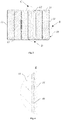
Fig. 1 is a schematic perspective view of a battery module according to an embodiment of the present disclosure; -
Fig. 2 is a schematic view of a breakdown structure of the battery module shown inFig. 1 ; -
Fig. 3 is a sectional view taken along direction A-A shown inFig. 1 ; -
Fig. 4 is a schematic enlarged partial view of a region B of the battery module shown inFig. 3 ; -
Fig. 5 is a schematic enlarged partial view of a region C of the battery module shown inFig. 3 ; -
Fig. 6 is a schematic enlarged partial view of a region D of the battery module shown inFig. 3 . -
- 10- Housing
- 11- Side plate
- 12- Top plate
- 13- Bottom plate
- 20- End plate
- 30- Battery stack
- 31- Battery
- 40- Heat insulator
- 50- Cushion
- 60- Heat conductor
- In the drawings, the same reference signs denote the same features. The drawings are not shown in actual scale.
- The features and exemplary embodiments of the various aspects of the present disclosure will be described in detail below. In the following detailed description, numerous specific details are set forth in order to provide a thorough understanding of the present disclosure. It will be apparent, however, to those skilled in the art that the present disclosure may be practiced without some of these specific details. The following description of embodiments is only provided by illustrating examples for a better understanding of the present disclosure. In the drawings and the following description, at least a part of well-known structures and techniques are not shown in order to avoid unnecessarily obscuring the present disclosure. Further, for clarity, the size of a part of the structures may be exaggerated. Furthermore, the features, structures, or characteristics described below can be combined in any suitable manner in one or more embodiments.
- The terms denoting directions that appear in the following description indicate directions shown in the drawings, and do not limit specific structures of the secondary battery of the present disclosure. In the description of the present disclosure, it should also be noted that the terms "mounted", "connected" and "connection" should be interpreted in a broad sense unless explicitly defined and limited otherwise. For example, it may indicate "fixed connection", "disassemble connection" or "integral connection"; it may indicate a direct connection or an indirect connection. For those skilled in the art, specific meanings of the above terms in the present disclosure may be understood depending on specific situations.
- For a better understanding of the present disclosure, a battery module according to embodiments of the present disclosure will be described in detail below with reference to
Fig. 1 to Fig. 6 . - Referring to
Figs. 1 to 6 , an embodiment of the present disclosure provides a battery module including ahousing 10, twoend plates 20, abattery stack 30, aheat insulator 40, and acushion 50. - The
housing 10 includes atop plate 12, abottom plate 13, and twoside plates 11. Thetop plate 12 and thebottom plate 13 are disposed opposite to each other. The twoside plates 11 are connected to thetop plate 12 and thebottom plate 13 and spaced along a first direction D1. The first direction D1 is shown by an arrow inFig. 1 . Thehousing 10 may be made of aluminum alloy, stainless steel, or iron. The embodiments of the present disclosure are described with astainless steel housing 10. - The two
end plates 20 are spaced along a second direction D2 perpendicular to the first direction D1. The twoside plates 11 are alternated with the twoend plates 20 and connected to each other. The second direction D2 is shown by an arrow inFig. 1 . - The
battery stack 30 may include a plurality ofbatteries 31 arranged side by side between the twoside plates 11. Each of the plurality ofbatteries 31 extends between the twoend plates 20 in the second direction D2. Thebattery 31 includes a plastic shell, an aluminum alloy shell, a stainless steel shell, or an iron shell. The plastic shell may be made of, for example but not limited to, polypropylene (PP). - As shown in
Fig. 4 , theheat insulator 40 may be disposed between thebattery stack 30 and theside plates 11 to effectively isolate the heat between theside plates 11 and the neighboringbatteries 31 and control uniform heat delivery between eachbattery 31. - The
cushion 50 may be disposed between thebattery stack 30 and thetop plate 12 and/or between thebattery stack 30 and thebottom plate 13. Thecushion 50 may be an elastic member with a certain thickness for preventing thebattery stack 30 from being moving between thetop plate 12 and thebottom plate 13 of thehousing 10. - Specifically, as shown in
Fig. 2 , sixbatteries 31, for example, are assembled into abattery stack 30 and assembled in analuminum alloy housing 10. Twoend plates 20 are respectively welded to both ends of thehousing 10 to form a closed cavity. Both ends of eachbattery 31 are respectively provided with output terminals that are connected to theend plates 20. Thebattery stack 30 is accommodated in thehousing 10, and a cushion is disposed between thebattery stack 30 and thetop plate 12. Thebatteries 31 adjacent to the twoside plates 11 of thehousing 10 have more heat conduction paths than thebatteries 31 located in the middle of thehousing 10, as a result, the heat conduction efficiency among thebatteries 31 of thebattery stack 30 is different. If theheat insulator 40 is disposed between theside plates 11 and thebattery stack 30, the heat between the side plates and theadjacent batteries 31 can be effectively isolated, so that the heat conduction paths between eachbattery 31 and thehousings 10 are the same. As a result, the heat conduction efficiency may be uniform. In this way, uniform cooling of eachbattery 31 can be achieved when thehousing 10 is cooled. - According to the battery module provided in an embodiment of the present disclosure, the
heat insulator 40 is disposed between theside plates 11 of thehousing 10 and thebattery stack 30. In this way, the heat conduction paths and heat conduction efficiency between thehousing 10 and the plurality ofbatteries 31 arranged side by side in thehousing 10 are the same, so that the temperature uniformity among theindividual batteries 31 can be ensured, and the reliability of the battery module is improved. - In order to improve heat dissipation efficiency while keeping uniform heat dissipation, the battery module according to an embodiment of the present disclosure may further include a
heat conductor 60, especially for abattery 31 with a plastic housing. - As an optional embodiment, the
heat conductor 60 may be disposed between thetop plate 12 and thebattery stack 30 and/or between thebottom plate 13 and thebattery stack 30. For example, theheat conductor 60 may be disposed between thebottom plate 13 and thebattery stack 30, as shown inFig. 6 . - As an optional embodiment, the
battery stack 30 may include oppositely disposed top end and bottom end, and at least one of the top end and bottom end may be disposed with aheat conductor 60. Furthermore, theheat conductor 60 may be disposed in contact with eachbattery 31. - Specifically, when the
heat conductor 60 is disposed between thetop plate 12 and thebattery stack 30, thecushion 50 may be disposed between thebottom plate 13 and thebattery stack 30; and when theheat conductor 60 is disposed between thebottom plate 13 and thebattery stack 30, thecushion 50 may be disposed between thetop plate 12 and theheat conductor 60, as shown inFig. 5 . Whenheat conductors 60 are disposed between thetop plate 12 and thebattery stack 30 and between thebottom plate 13 and thebattery stack 30, thecushion 50 may be disposed between thetop plate 12 and theheat conductor 60 and/or between thebottom plate 13 and theheat conductor 60. - As an optional embodiment, a
heat conductor 60 may be disposed between twoadjacent batteries 31 in thebattery stack 30. Theheat conductor 60 may enable quick transfer of heat of theindividual batteries 31 in the direction of the top plate or the bottom plate of thehousing 10. Theheat conductor 60 disposed between twoadjacent batteries 31 may also enable quick transfer of heat of theindividual batteries 31 in the direction of the top plate or the bottom plate of thehousing 10 along with the above heat conductor (s) 60 disposed between thetop plate 12 and thebattery stack 30 and/or between thebottom plate 13 and thebattery stack 30, so that the number of heat conduction paths may be further increased. The plurality ofheat conductors 60 may serve as heat transfer medium between thebattery stack 30 and thehousing 10, and therefore uniform transfer of heat among theindividual batteries 31 can be more effectively controlled. - Further, in order to facilitate forming of the
battery stack 30 from the plurality ofbatteries 31 and assembling of thebattery stack 30 into the cavity of thehousing 10, a gap may be provided between thebattery stack 30 and theside plates 11. For example, the wall thickness of the plastic housing of thebattery 31 is 0.5 mm; the wall thickness of thealuminum alloy housing 10 is 1 mm; and the thickness of theheat conductor 60 and theheat insulator 40 is generally 0.5 mm to 3 mm, for example, 1 mm. Then the gap may also be set to 1 mm to facilitate the assembly of theheat insulators 40 between theside plates 11 of thealuminum alloy housing 10 and thebattery stack 30. - According to an optional embodiment, the
heat conductor 60 may be a silicon plate with a heat conduction coefficient of 1 W/m•K∼3 W/m•K. - According to an optional embodiment, the
heat insulator 40 may be an ethylene propylene diene monomer (EPDM) plate with a heat conduction coefficient less than or equal to 0.05 W/m•K. - It should be understood that, the battery modules provided in the embodiments of the present disclosure may be applicable to any type of battery module, including but not limited to lithium-ion battery, lead battery, and the like, which will not be described herein.
- Therefore, according to the battery modules provided in the embodiments of the present disclosure,
heat insulators 40 are disposed between theside plates 11 of thehousing 10 and thebattery stack 30, and furthermore,heat conductors 60 are disposed between thetop plate 12 and/or thebottom plate 13 of thehousing 10 and thebattery stack 30 as well as betweenadjacent batteries 31. In this way, the heat conduction paths and heat conduction efficiency among the plurality ofbatteries 31 arranged side by side in thehousing 10 are the same, and furthermore, the heat conduction efficiency can be improved. As a result, the temperature uniformity among theindividual batteries 31 can be ensured, and the reliability of the battery module is improved. - Although the present disclosure has been described with reference to some embodiments, various modifications may be made thereto without departing from the scope of the present disclosure and components herein may be replaced with equivalents thereof. In particular, as long as there is no structural conflict, the various technical features mentioned in the various embodiments may be combined in any manner. The present disclosure is not limited to the specific embodiments disclosed herein, but includes all technical solutions that fall within the scope of the claims.
Claims (10)
- A battery module, comprising:a housing (10) comprising a top plate (12) and a bottom plate (13) which are disposed opposite to each other, and two side plates (11) which are connected to the top plate (12) and the bottom plate (13) and spaced along a first direction (D1);two end plates (20) spaced along a second direction (D2) which is perpendicular to the first direction (D1), wherein the two side plates (11) are alternately connected with the two end plates (20);a battery stack (30) comprising a plurality of batteries (31) arranged side by side between the two side plates (11), wherein the plurality of batteries (31) extend between the two end plates (20) in the second direction (D2);heat insulators (40) disposed between the battery stack (30) and the side plates (11); anda cushion (50) disposed between the battery stack (30) and at least one of the top plate (12) and the bottom plate (13).
- The battery module of claim 1, wherein the battery module further comprises a heat conductor (60) which is disposed between the battery stack (30) and at least one of the top plate (12) and the bottom plate (13).
- The battery module of claim 2, wherein the battery stack (30) comprises a top end and a bottom end which are opposite to one another, and wherein at least one of the top end and the bottom end is disposed with the heat conductor (60).
- The battery module of claim 3, wherein the heat conductor (60) is disposed in contact with each battery (31).
- The battery module of any of claims 1 to 4, wherein a heat conductor (60) is further disposed between two adjacent batteries (31) in the battery stack (30).
- The battery module of claim 1, wherein the housing (10) is made of aluminum alloy, stainless steel or iron.
- The battery module of claim 1, wherein one of the plurality of batteries (31) includes a plastic shell, an aluminum alloy shell, a stainless steel shell, or an iron shell.
- The battery module of claim 1, wherein a gap is provided between the battery stack (30) and the side plates (11).
- The battery module of claim 2, wherein the heat conductor (60) is a silicon plate with a heat conduction coefficient of 1 W/m•K∼3 W/m•K.
- The battery module of claim 1, wherein the heat insulator (40) is an ethylene propylene diene monomer (EPDM) plate with a heat conduction coefficient less than or equal to 0.05 W/m•K.
Applications Claiming Priority (1)
| Application Number | Priority Date | Filing Date | Title |
|---|---|---|---|
| CN201820205762.9U CN207800719U (en) | 2018-02-06 | 2018-02-06 | Battery modules |
Publications (2)
| Publication Number | Publication Date |
|---|---|
| EP3522293A1 true EP3522293A1 (en) | 2019-08-07 |
| EP3522293B1 EP3522293B1 (en) | 2020-05-13 |
Family
ID=63012926
Family Applications (1)
| Application Number | Title | Priority Date | Filing Date |
|---|---|---|---|
| EP18184517.3A Active EP3522293B1 (en) | 2018-02-06 | 2018-07-19 | Battery module |
Country Status (5)
| Country | Link |
|---|---|
| US (1) | US20190245168A1 (en) |
| EP (1) | EP3522293B1 (en) |
| JP (1) | JP6581699B2 (en) |
| CN (1) | CN207800719U (en) |
| HU (1) | HUE050449T2 (en) |
Families Citing this family (8)
| Publication number | Priority date | Publication date | Assignee | Title |
|---|---|---|---|---|
| KR102317638B1 (en) * | 2018-12-05 | 2021-10-25 | 주식회사 엘지에너지솔루션 | Battery module having protection structure of cell stack |
| CN111355004B (en) * | 2018-12-21 | 2021-06-08 | 江苏时代新能源科技有限公司 | Battery module |
| DE102019215635A1 (en) * | 2019-10-11 | 2021-04-15 | Robert Bosch Gmbh | Battery module |
| DE102019215636A1 (en) | 2019-10-11 | 2021-04-15 | Robert Bosch Gmbh | Battery module |
| WO2021092754A1 (en) * | 2019-11-12 | 2021-05-20 | 上海汽车集团股份有限公司 | Battery energy storage module and battery energy storage device |
| JP2021118165A (en) * | 2020-01-29 | 2021-08-10 | パナソニックIpマネジメント株式会社 | Battery pack and power tool |
| CN112310535B (en) * | 2020-07-31 | 2023-11-21 | 宁德时代新能源科技股份有限公司 | Battery pack, power consumption device, and method for manufacturing battery pack |
| CN113747712A (en) * | 2021-09-01 | 2021-12-03 | 北京恒润安科技有限公司 | Integrated form integration data acquisition device |
Citations (2)
| Publication number | Priority date | Publication date | Assignee | Title |
|---|---|---|---|---|
| US20130130087A1 (en) * | 2011-07-05 | 2013-05-23 | Hitachi, Ltd. | Non-aqueous electrolyte battery module |
| US20140011059A1 (en) * | 2011-03-31 | 2014-01-09 | Hiroyuki Hashimoto | Power supply device and vehicle equipped therewith |
Family Cites Families (6)
| Publication number | Priority date | Publication date | Assignee | Title |
|---|---|---|---|---|
| US4738906A (en) * | 1985-04-30 | 1988-04-19 | Weather Ready Inc. | Storage battery heating and heat maintenance apparatus |
| JP2010086885A (en) * | 2008-10-02 | 2010-04-15 | Sr:Kk | Storage container for used battery |
| US9595733B2 (en) * | 2010-10-19 | 2017-03-14 | GM Global Technology Operations LLC | Battery modules and assemblies |
| US9647302B2 (en) * | 2012-12-05 | 2017-05-09 | GM Global Technology Operations LLC | Battery thermal system with a stacking frame |
| JP2014138483A (en) * | 2013-01-16 | 2014-07-28 | Sanyo Electric Co Ltd | Battery pack and electric apparatus |
| US20170015803A1 (en) * | 2015-07-13 | 2017-01-19 | Armacell Enterprise Gmbh & Co. Kg | Compressible fire retardant foam |
-
2018
- 2018-02-06 CN CN201820205762.9U patent/CN207800719U/en active Active
- 2018-07-16 US US16/036,935 patent/US20190245168A1/en not_active Abandoned
- 2018-07-19 HU HUE18184517A patent/HUE050449T2/en unknown
- 2018-07-19 EP EP18184517.3A patent/EP3522293B1/en active Active
- 2018-07-30 JP JP2018142012A patent/JP6581699B2/en active Active
Patent Citations (2)
| Publication number | Priority date | Publication date | Assignee | Title |
|---|---|---|---|---|
| US20140011059A1 (en) * | 2011-03-31 | 2014-01-09 | Hiroyuki Hashimoto | Power supply device and vehicle equipped therewith |
| US20130130087A1 (en) * | 2011-07-05 | 2013-05-23 | Hitachi, Ltd. | Non-aqueous electrolyte battery module |
Also Published As
| Publication number | Publication date |
|---|---|
| HUE050449T2 (en) | 2020-12-28 |
| US20190245168A1 (en) | 2019-08-08 |
| JP6581699B2 (en) | 2019-09-25 |
| CN207800719U (en) | 2018-08-31 |
| EP3522293B1 (en) | 2020-05-13 |
| JP2019140082A (en) | 2019-08-22 |
Similar Documents
| Publication | Publication Date | Title |
|---|---|---|
| EP3522293B1 (en) | Battery module | |
| EP2432045B1 (en) | Battery cartridge having elastic pressing member, and battery module cotaining the same | |
| EP2654101B1 (en) | Battery pack | |
| US9991569B2 (en) | Battery module | |
| EP2366202B1 (en) | Battery module having cooling means, and middle or large-sized battery pack containing the same | |
| EP3506383B1 (en) | Battery module | |
| CN104064834A (en) | Heat Conduction Structure | |
| KR102210218B1 (en) | Battery system, base plate for a battery system and electric vehicle | |
| EP3648198A1 (en) | Secondary battery | |
| CN216624395U (en) | Battery module | |
| US20230026926A1 (en) | Battery, power consumption device, and method and device for producing battery | |
| KR100648732B1 (en) | Secondary battery module | |
| EP3540820B1 (en) | Battery pack | |
| US20100159316A1 (en) | Secondary battery module | |
| US11342633B2 (en) | Current collecting system for battery module, battery module, and vehicle | |
| US20230163405A1 (en) | Battery cell, battery, electrical device and device and method for preparing battery cell | |
| CN218887318U (en) | Battery pack | |
| US20230307740A1 (en) | Battery cell, battery, apparatus, and method and device for manufacturing battery cell | |
| EP4340098A1 (en) | Battery cooling fin and battery cooling system including the same | |
| WO2024037133A1 (en) | Battery pack and vehicle | |
| EP4266465A1 (en) | Battery module | |
| CN117638423A (en) | Battery pack and vehicle | |
| KR20140015840A (en) | Battery cell for secondary battery | |
| CN117638392A (en) | Single battery, battery pack and vehicle | |
| KR20230106219A (en) | Vehicle battery module and manufacturing method thereof |
Legal Events
| Date | Code | Title | Description |
|---|---|---|---|
| PUAI | Public reference made under article 153(3) epc to a published international application that has entered the european phase |
Free format text: ORIGINAL CODE: 0009012 |
|
| STAA | Information on the status of an ep patent application or granted ep patent |
Free format text: STATUS: REQUEST FOR EXAMINATION WAS MADE |
|
| 17P | Request for examination filed |
Effective date: 20190408 |
|
| AK | Designated contracting states |
Kind code of ref document: A1 Designated state(s): AL AT BE BG CH CY CZ DE DK EE ES FI FR GB GR HR HU IE IS IT LI LT LU LV MC MK MT NL NO PL PT RO RS SE SI SK SM TR |
|
| AX | Request for extension of the european patent |
Extension state: BA ME |
|
| GRAP | Despatch of communication of intention to grant a patent |
Free format text: ORIGINAL CODE: EPIDOSNIGR1 |
|
| STAA | Information on the status of an ep patent application or granted ep patent |
Free format text: STATUS: GRANT OF PATENT IS INTENDED |
|
| RIC1 | Information provided on ipc code assigned before grant |
Ipc: H01M 10/658 20140101AFI20200115BHEP Ipc: H01M 10/653 20140101ALI20200115BHEP Ipc: H01M 10/617 20140101ALI20200115BHEP Ipc: H01M 2/10 20060101ALI20200115BHEP Ipc: H01M 10/6555 20140101ALI20200115BHEP Ipc: H01M 10/6554 20140101ALI20200115BHEP Ipc: H01M 10/647 20140101ALI20200115BHEP |
|
| INTG | Intention to grant announced |
Effective date: 20200218 |
|
| GRAS | Grant fee paid |
Free format text: ORIGINAL CODE: EPIDOSNIGR3 |
|
| GRAA | (expected) grant |
Free format text: ORIGINAL CODE: 0009210 |
|
| STAA | Information on the status of an ep patent application or granted ep patent |
Free format text: STATUS: THE PATENT HAS BEEN GRANTED |
|
| AK | Designated contracting states |
Kind code of ref document: B1 Designated state(s): AL AT BE BG CH CY CZ DE DK EE ES FI FR GB GR HR HU IE IS IT LI LT LU LV MC MK MT NL NO PL PT RO RS SE SI SK SM TR |
|
| REG | Reference to a national code |
Ref country code: GB Ref legal event code: FG4D |
|
| REG | Reference to a national code |
Ref country code: CH Ref legal event code: EP |
|
| REG | Reference to a national code |
Ref country code: DE Ref legal event code: R096 Ref document number: 602018004463 Country of ref document: DE |
|
| REG | Reference to a national code |
Ref country code: AT Ref legal event code: REF Ref document number: 1271461 Country of ref document: AT Kind code of ref document: T Effective date: 20200615 |
|
| REG | Reference to a national code |
Ref country code: NL Ref legal event code: FP |
|
| REG | Reference to a national code |
Ref country code: LT Ref legal event code: MG4D |
|
| PG25 | Lapsed in a contracting state [announced via postgrant information from national office to epo] |
Ref country code: FI Free format text: LAPSE BECAUSE OF FAILURE TO SUBMIT A TRANSLATION OF THE DESCRIPTION OR TO PAY THE FEE WITHIN THE PRESCRIBED TIME-LIMIT Effective date: 20200513 Ref country code: GR Free format text: LAPSE BECAUSE OF FAILURE TO SUBMIT A TRANSLATION OF THE DESCRIPTION OR TO PAY THE FEE WITHIN THE PRESCRIBED TIME-LIMIT Effective date: 20200814 Ref country code: PT Free format text: LAPSE BECAUSE OF FAILURE TO SUBMIT A TRANSLATION OF THE DESCRIPTION OR TO PAY THE FEE WITHIN THE PRESCRIBED TIME-LIMIT Effective date: 20200914 Ref country code: SE Free format text: LAPSE BECAUSE OF FAILURE TO SUBMIT A TRANSLATION OF THE DESCRIPTION OR TO PAY THE FEE WITHIN THE PRESCRIBED TIME-LIMIT Effective date: 20200513 Ref country code: NO Free format text: LAPSE BECAUSE OF FAILURE TO SUBMIT A TRANSLATION OF THE DESCRIPTION OR TO PAY THE FEE WITHIN THE PRESCRIBED TIME-LIMIT Effective date: 20200813 Ref country code: IS Free format text: LAPSE BECAUSE OF FAILURE TO SUBMIT A TRANSLATION OF THE DESCRIPTION OR TO PAY THE FEE WITHIN THE PRESCRIBED TIME-LIMIT Effective date: 20200913 Ref country code: LT Free format text: LAPSE BECAUSE OF FAILURE TO SUBMIT A TRANSLATION OF THE DESCRIPTION OR TO PAY THE FEE WITHIN THE PRESCRIBED TIME-LIMIT Effective date: 20200513 |
|
| PG25 | Lapsed in a contracting state [announced via postgrant information from national office to epo] |
Ref country code: BG Free format text: LAPSE BECAUSE OF FAILURE TO SUBMIT A TRANSLATION OF THE DESCRIPTION OR TO PAY THE FEE WITHIN THE PRESCRIBED TIME-LIMIT Effective date: 20200813 Ref country code: RS Free format text: LAPSE BECAUSE OF FAILURE TO SUBMIT A TRANSLATION OF THE DESCRIPTION OR TO PAY THE FEE WITHIN THE PRESCRIBED TIME-LIMIT Effective date: 20200513 Ref country code: HR Free format text: LAPSE BECAUSE OF FAILURE TO SUBMIT A TRANSLATION OF THE DESCRIPTION OR TO PAY THE FEE WITHIN THE PRESCRIBED TIME-LIMIT Effective date: 20200513 Ref country code: LV Free format text: LAPSE BECAUSE OF FAILURE TO SUBMIT A TRANSLATION OF THE DESCRIPTION OR TO PAY THE FEE WITHIN THE PRESCRIBED TIME-LIMIT Effective date: 20200513 |
|
| REG | Reference to a national code |
Ref country code: AT Ref legal event code: MK05 Ref document number: 1271461 Country of ref document: AT Kind code of ref document: T Effective date: 20200513 |
|
| REG | Reference to a national code |
Ref country code: HU Ref legal event code: AG4A Ref document number: E050449 Country of ref document: HU |
|
| PG25 | Lapsed in a contracting state [announced via postgrant information from national office to epo] |
Ref country code: AL Free format text: LAPSE BECAUSE OF FAILURE TO SUBMIT A TRANSLATION OF THE DESCRIPTION OR TO PAY THE FEE WITHIN THE PRESCRIBED TIME-LIMIT Effective date: 20200513 |
|
| PG25 | Lapsed in a contracting state [announced via postgrant information from national office to epo] |
Ref country code: ES Free format text: LAPSE BECAUSE OF FAILURE TO SUBMIT A TRANSLATION OF THE DESCRIPTION OR TO PAY THE FEE WITHIN THE PRESCRIBED TIME-LIMIT Effective date: 20200513 Ref country code: DK Free format text: LAPSE BECAUSE OF FAILURE TO SUBMIT A TRANSLATION OF THE DESCRIPTION OR TO PAY THE FEE WITHIN THE PRESCRIBED TIME-LIMIT Effective date: 20200513 Ref country code: AT Free format text: LAPSE BECAUSE OF FAILURE TO SUBMIT A TRANSLATION OF THE DESCRIPTION OR TO PAY THE FEE WITHIN THE PRESCRIBED TIME-LIMIT Effective date: 20200513 Ref country code: SM Free format text: LAPSE BECAUSE OF FAILURE TO SUBMIT A TRANSLATION OF THE DESCRIPTION OR TO PAY THE FEE WITHIN THE PRESCRIBED TIME-LIMIT Effective date: 20200513 Ref country code: IT Free format text: LAPSE BECAUSE OF FAILURE TO SUBMIT A TRANSLATION OF THE DESCRIPTION OR TO PAY THE FEE WITHIN THE PRESCRIBED TIME-LIMIT Effective date: 20200513 Ref country code: EE Free format text: LAPSE BECAUSE OF FAILURE TO SUBMIT A TRANSLATION OF THE DESCRIPTION OR TO PAY THE FEE WITHIN THE PRESCRIBED TIME-LIMIT Effective date: 20200513 Ref country code: RO Free format text: LAPSE BECAUSE OF FAILURE TO SUBMIT A TRANSLATION OF THE DESCRIPTION OR TO PAY THE FEE WITHIN THE PRESCRIBED TIME-LIMIT Effective date: 20200513 Ref country code: CZ Free format text: LAPSE BECAUSE OF FAILURE TO SUBMIT A TRANSLATION OF THE DESCRIPTION OR TO PAY THE FEE WITHIN THE PRESCRIBED TIME-LIMIT Effective date: 20200513 |
|
| REG | Reference to a national code |
Ref country code: DE Ref legal event code: R097 Ref document number: 602018004463 Country of ref document: DE |
|
| PG25 | Lapsed in a contracting state [announced via postgrant information from national office to epo] |
Ref country code: MC Free format text: LAPSE BECAUSE OF FAILURE TO SUBMIT A TRANSLATION OF THE DESCRIPTION OR TO PAY THE FEE WITHIN THE PRESCRIBED TIME-LIMIT Effective date: 20200513 Ref country code: PL Free format text: LAPSE BECAUSE OF FAILURE TO SUBMIT A TRANSLATION OF THE DESCRIPTION OR TO PAY THE FEE WITHIN THE PRESCRIBED TIME-LIMIT Effective date: 20200513 Ref country code: SK Free format text: LAPSE BECAUSE OF FAILURE TO SUBMIT A TRANSLATION OF THE DESCRIPTION OR TO PAY THE FEE WITHIN THE PRESCRIBED TIME-LIMIT Effective date: 20200513 |
|
| PLBE | No opposition filed within time limit |
Free format text: ORIGINAL CODE: 0009261 |
|
| STAA | Information on the status of an ep patent application or granted ep patent |
Free format text: STATUS: NO OPPOSITION FILED WITHIN TIME LIMIT |
|
| 26N | No opposition filed |
Effective date: 20210216 |
|
| PG25 | Lapsed in a contracting state [announced via postgrant information from national office to epo] |
Ref country code: LU Free format text: LAPSE BECAUSE OF NON-PAYMENT OF DUE FEES Effective date: 20200719 |
|
| PG25 | Lapsed in a contracting state [announced via postgrant information from national office to epo] |
Ref country code: IE Free format text: LAPSE BECAUSE OF NON-PAYMENT OF DUE FEES Effective date: 20200719 |
|
| REG | Reference to a national code |
Ref country code: CH Ref legal event code: PL |
|
| PG25 | Lapsed in a contracting state [announced via postgrant information from national office to epo] |
Ref country code: LI Free format text: LAPSE BECAUSE OF NON-PAYMENT OF DUE FEES Effective date: 20210731 Ref country code: CH Free format text: LAPSE BECAUSE OF NON-PAYMENT OF DUE FEES Effective date: 20210731 |
|
| PG25 | Lapsed in a contracting state [announced via postgrant information from national office to epo] |
Ref country code: TR Free format text: LAPSE BECAUSE OF FAILURE TO SUBMIT A TRANSLATION OF THE DESCRIPTION OR TO PAY THE FEE WITHIN THE PRESCRIBED TIME-LIMIT Effective date: 20200513 Ref country code: MT Free format text: LAPSE BECAUSE OF FAILURE TO SUBMIT A TRANSLATION OF THE DESCRIPTION OR TO PAY THE FEE WITHIN THE PRESCRIBED TIME-LIMIT Effective date: 20200513 Ref country code: CY Free format text: LAPSE BECAUSE OF FAILURE TO SUBMIT A TRANSLATION OF THE DESCRIPTION OR TO PAY THE FEE WITHIN THE PRESCRIBED TIME-LIMIT Effective date: 20200513 |
|
| PG25 | Lapsed in a contracting state [announced via postgrant information from national office to epo] |
Ref country code: MK Free format text: LAPSE BECAUSE OF FAILURE TO SUBMIT A TRANSLATION OF THE DESCRIPTION OR TO PAY THE FEE WITHIN THE PRESCRIBED TIME-LIMIT Effective date: 20200513 |
|
| P01 | Opt-out of the competence of the unified patent court (upc) registered |
Effective date: 20230516 |
|
| PGFP | Annual fee paid to national office [announced via postgrant information from national office to epo] |
Ref country code: NL Payment date: 20230614 Year of fee payment: 6 Ref country code: FR Payment date: 20230523 Year of fee payment: 6 |
|
| PG25 | Lapsed in a contracting state [announced via postgrant information from national office to epo] |
Ref country code: SI Free format text: LAPSE BECAUSE OF FAILURE TO SUBMIT A TRANSLATION OF THE DESCRIPTION OR TO PAY THE FEE WITHIN THE PRESCRIBED TIME-LIMIT Effective date: 20200513 |
|
| PGFP | Annual fee paid to national office [announced via postgrant information from national office to epo] |
Ref country code: BE Payment date: 20230616 Year of fee payment: 6 |
|
| PGFP | Annual fee paid to national office [announced via postgrant information from national office to epo] |
Ref country code: GB Payment date: 20230525 Year of fee payment: 6 |
|
| PGFP | Annual fee paid to national office [announced via postgrant information from national office to epo] |
Ref country code: HU Payment date: 20230531 Year of fee payment: 6 Ref country code: DE Payment date: 20230524 Year of fee payment: 6 |